US12113548B2 - Method and apparatus for encoding polar code, and method and apparatus for decoding polar code - Google Patents
Method and apparatus for encoding polar code, and method and apparatus for decoding polar code Download PDFInfo
- Publication number
- US12113548B2 US12113548B2 US18/183,272 US202318183272A US12113548B2 US 12113548 B2 US12113548 B2 US 12113548B2 US 202318183272 A US202318183272 A US 202318183272A US 12113548 B2 US12113548 B2 US 12113548B2
- Authority
- US
- United States
- Prior art keywords
- kernel matrix
- line
- target
- encoding method
- indicates
- Prior art date
- Legal status (The legal status is an assumption and is not a legal conclusion. Google has not performed a legal analysis and makes no representation as to the accuracy of the status listed.)
- Active
Links
Images


Classifications
-
- H—ELECTRICITY
- H03—ELECTRONIC CIRCUITRY
- H03M—CODING; DECODING; CODE CONVERSION IN GENERAL
- H03M13/00—Coding, decoding or code conversion, for error detection or error correction; Coding theory basic assumptions; Coding bounds; Error probability evaluation methods; Channel models; Simulation or testing of codes
- H03M13/03—Error detection or forward error correction by redundancy in data representation, i.e. code words containing more digits than the source words
- H03M13/05—Error detection or forward error correction by redundancy in data representation, i.e. code words containing more digits than the source words using block codes, i.e. a predetermined number of check bits joined to a predetermined number of information bits
- H03M13/13—Linear codes
-
- H—ELECTRICITY
- H03—ELECTRONIC CIRCUITRY
- H03M—CODING; DECODING; CODE CONVERSION IN GENERAL
- H03M13/00—Coding, decoding or code conversion, for error detection or error correction; Coding theory basic assumptions; Coding bounds; Error probability evaluation methods; Channel models; Simulation or testing of codes
- H03M13/65—Purpose and implementation aspects
- H03M13/6502—Reduction of hardware complexity or efficient processing
-
- H—ELECTRICITY
- H04—ELECTRIC COMMUNICATION TECHNIQUE
- H04L—TRANSMISSION OF DIGITAL INFORMATION, e.g. TELEGRAPHIC COMMUNICATION
- H04L1/00—Arrangements for detecting or preventing errors in the information received
- H04L1/004—Arrangements for detecting or preventing errors in the information received by using forward error control
- H04L1/0041—Arrangements at the transmitter end
-
- H—ELECTRICITY
- H04—ELECTRIC COMMUNICATION TECHNIQUE
- H04L—TRANSMISSION OF DIGITAL INFORMATION, e.g. TELEGRAPHIC COMMUNICATION
- H04L1/00—Arrangements for detecting or preventing errors in the information received
- H04L1/004—Arrangements for detecting or preventing errors in the information received by using forward error control
- H04L1/0045—Arrangements at the receiver end
- H04L1/0052—Realisations of complexity reduction techniques, e.g. pipelining or use of look-up tables
-
- H—ELECTRICITY
- H04—ELECTRIC COMMUNICATION TECHNIQUE
- H04L—TRANSMISSION OF DIGITAL INFORMATION, e.g. TELEGRAPHIC COMMUNICATION
- H04L1/00—Arrangements for detecting or preventing errors in the information received
- H04L1/004—Arrangements for detecting or preventing errors in the information received by using forward error control
- H04L1/0056—Systems characterized by the type of code used
- H04L1/0057—Block codes
-
- H—ELECTRICITY
- H04—ELECTRIC COMMUNICATION TECHNIQUE
- H04L—TRANSMISSION OF DIGITAL INFORMATION, e.g. TELEGRAPHIC COMMUNICATION
- H04L1/00—Arrangements for detecting or preventing errors in the information received
- H04L1/004—Arrangements for detecting or preventing errors in the information received by using forward error control
- H04L1/0056—Systems characterized by the type of code used
- H04L1/0067—Rate matching
- H04L1/0068—Rate matching by puncturing
- H04L1/0069—Puncturing patterns
-
- H—ELECTRICITY
- H04—ELECTRIC COMMUNICATION TECHNIQUE
- H04L—TRANSMISSION OF DIGITAL INFORMATION, e.g. TELEGRAPHIC COMMUNICATION
- H04L1/00—Arrangements for detecting or preventing errors in the information received
- H04L1/004—Arrangements for detecting or preventing errors in the information received by using forward error control
- H04L1/0072—Error control for data other than payload data, e.g. control data
-
- H—ELECTRICITY
- H03—ELECTRONIC CIRCUITRY
- H03M—CODING; DECODING; CODE CONVERSION IN GENERAL
- H03M13/00—Coding, decoding or code conversion, for error detection or error correction; Coding theory basic assumptions; Coding bounds; Error probability evaluation methods; Channel models; Simulation or testing of codes
- H03M13/37—Decoding methods or techniques, not specific to the particular type of coding provided for in groups H03M13/03 - H03M13/35
- H03M13/39—Sequence estimation, i.e. using statistical methods for the reconstruction of the original codes
- H03M13/3905—Maximum a posteriori probability [MAP] decoding or approximations thereof based on trellis or lattice decoding, e.g. forward-backward algorithm, log-MAP decoding, max-log-MAP decoding
- H03M13/3916—Maximum a posteriori probability [MAP] decoding or approximations thereof based on trellis or lattice decoding, e.g. forward-backward algorithm, log-MAP decoding, max-log-MAP decoding for block codes using a trellis or lattice
Definitions
- This application relates to the field of channel coding, and to a method and an apparatus for encoding a polar code, and a method and an apparatus for decoding a polar code.
- a polar code has been strictly proved to be a channel encoding scheme that reaches a channel capacity, and has features such as high performance, low complexity, and a flexible matching manner.
- the polar code is determined by the 3 rd Generation Partnership Project (3GPP) as a control channel encoding scheme in some communication scenarios of the 5 th generation (5G).
- An original polar code is based on a kernel matrix
- a high-dimensional kernel matrix researchers have proved that a polarization speed when some well-designed high-dimensional kernel matrices are used to encode the polar code is higher, in other words, decoding performance is better.
- the high-dimensional kernel matrix causes high decoding complexity, and how to reduce decoding complexity is an urgent problem to be resolved.
- Embodiments described herein provide a method and an apparatus for encoding a polar code, and a method and an apparatus for decoding a polar code, to reduce decoding complexity.
- an encoding method is provided.
- the method is performed by an encoder device, or is performed by a chip, a chip system, or a circuit set in the encoder device. This is not limited in at least one embodiment.
- the method includes: obtaining information bits; determining a target kernel matrix, where the target kernel matrix is obtained by adjusting an original kernel matrix; and performing polar encoding on the information bits based on the target kernel matrix.
- the obtaining information bits includes internally generating information bits, or includes receiving information bits from outside.
- a plurality of kernel matrices is constructed based on the original kernel matrix, and an appropriate target kernel matrix is selected for encoding based on the constructed kernel matrices and an actual communication status.
- performance and decoding complexity are comprehensively considered, so that decoding complexity is reduced by selecting the appropriate kernel matrix used during encoding.
- a dimension of the target kernel matrix is less than a dimension of the original kernel matrix.
- a plurality of kernel matrices whose dimensions are small are constructed based on a kernel matrix whose dimension is known. Encoding is performed based on the kernel matrix whose dimension is small, so that lower decoding complexity is provided while the same performance is ensured.
- the target kernel matrix is obtained by adjusting a partial distance of the original kernel matrix.
- the target kernel matrix is obtained by adjusting a partial distance profile (PDP) of the original kernel matrix.
- PDP partial distance profile
- the adjustment is performed based on partial distance close to that of an Arikan matrix.
- the target kernel matrix is obtained by adjusting the partial distance of the original kernel matrix according to a depth-first search algorithm.
- one or more of the following constraints are used for processing:
- the currently constructed kernel matrix K indicates that the kernel K is being constructed, or the kernel K been constructed indicates that the kernel K is constructed.
- a constraint condition about a candidate line and/or a selected line is designed, so as to accelerate convergence speed, thereby further reducing calculation amount.
- the original kernel matrix is a kernel matrix K 24 whose dimension is (24 ⁇ 24), and the K 24 is:
- the target kernel matrix is any one of the following:
- a decoding method is provided. The method is performed by a decoder device, or is performed by a chip, a chip system, or a circuit set in the decoder device. This is not limited in at least one embodiment.
- the method includes: obtaining a to-be-decoded sequence; and decoding the to-be-decoded sequence based on a plurality of trellises, and reusing an intermediate result obtained from decoding performed based on a first trellis in the plurality of trellises in response to decoding being performed based on a second trellis in the plurality of trellises, where the first trellis is used for a t th stage of decoding the to-be-decoded sequence, the second trellis is used for a (t+i) th stage of decoding the to-be-decoded sequence, t is an integer greater than 0 or equal to 0, and i is an integer greater than 1 or equal to 1.
- the obtaining the to-be-decoded sequence represents receiving the to-be-decoded sequence from outside.
- the first trellis corresponds to the t th stage of decoding.
- decoding is performed based on the first trellis; or in response to decoding being performed on an information bit of the to-be-decoded sequence, decoding is performed based on the first trellis.
- the second trellis corresponds to the (t+i) th stage of decoding.
- decoding is performed based on the second trellis; or in response to decoding being performed on another information bit of the to-be-decoded sequence, decoding is performed based on the second trellis.
- the intermediate result obtained through decoding performed based on the first trellis indicates a result obtained through processing based on the first trellis or a result obtained at the t th stage of decoding.
- the intermediate result includes, for example, a decoding path obtained through decoding performed based on the first trellis and a corresponding path measure value.
- a plurality of combinations are obtained after paths in a trellis of a smaller level are spliced, and an optimal path and a path value of a trellis of a larger level are obtained by selecting a path with a largest score in these combinations.
- each of the plurality of trellises is split into a plurality of sub-trellises.
- the trellis in response to the to-be-decoded sequence being decoded according to a decoding algorithm based on the trellis, the trellis is first split, and decoding based on a complete trellis is split into decoding based on a sub-trellis, thereby reducing decoding complexity.
- locations of split points of the plurality of sub-trellises are related to decoding complexity.
- the location of the split point at which the trellis is split is related to decoding complexity.
- the method further includes: determining, based on a correlation between the first trellis and the second trellis, whether to reuse the intermediate result obtained through decoding performed based on the first trellis in response to decoding being performed based on the second trellis.
- the correlation between the first trellis and the second trellis indicates whether the first trellis is the same as or similar to the second trellis; or indicates whether a plurality of sub-trellises corresponding to the first trellis are the same as or similar to a plurality of sub-trellises corresponding to the second trellis; or indicates whether a same calculation step exists in response to the processing being performed based on the first trellis and the second trellis.
- whether the intermediate results obtained in different decoding stages is reused is determined based on the correlation between the trellises, for example, whether the first trellis is the same as or similar to the second trellis.
- the decoding method further includes: determining, based on the following information, whether to reuse the intermediate result obtained through decoding performed based on the first trellis in response to decoding being performed based on the second trellis: a code obtained by performing a shortening operation on a linear code C in the (t+i) th stage of decoding and a code obtained by performing the shortening operation on the linear code C in the t th stage of decoding; and/or a code obtained by performing a puncturing operation on the linear code C in the (t+i) th stage of decoding and a code obtained by performing the puncturing operation on the linear code C in the t th stage of decoding.
- whether the intermediate results obtained in different decoding stages is reused is determined by comparing the code obtained by performing the shortening operation on the linear code C in different decoding stages and/or the code obtained by performing the puncturing operation on the linear code C in different decoding stages.
- s x,y (C (t+i) ) s x,y (C (t) ), and p x,y (C (t+i) ) ⁇ p x,y (C (t) ), reusing the intermediate result obtained through decoding performed based on the first trellis in response to decoding being performed based on the second trellis; or in response to s x,y (C (t+i) ) ⁇ s x,y (C (t) ), reusing the intermediate result obtained through decoding performed based on the first trellis in response to decoding being performed based on the second trellis, where s x,y (C (t+i) ) indicates a code obtained by performing the shortening operation on the linear code C at a location except x ⁇ z ⁇ y in the (t+i) th stage of decoding, s x,y (C (t) ) indicates a code obtained by performing the shortening operation on the linear code C at a location
- the reusing the intermediate result obtained through decoding performed based on the first trellis in response to decoding being performed based on the second trellis includes: in response to processing being performed based on the second trellis in the (t+i) th stage of decoding, directly using the intermediate result obtained through decoding performed based on the first trellis as an intermediate result obtained through decoding performed based on the second trellis; or in response to processing being performed based on the second trellis in the (t+i) th stage of decoding, performing processing based on a result of a maximization operation in a process of the first trellis.
- decoding is polar decoding.
- the to-be-decoded sequence is an obtained to-be-decoded sequence after the polar encoding.
- decoding complexity of a polar code decoder is high.
- decoding complexity is reduced by performing the decoding on the sub-trellis.
- encoding is performed by using an Arikan kernel and decoding is performed by using an SCL
- lower decoding complexity is provided while the same performance is ensured in this solution.
- At least one embodiment provides an encoding apparatus.
- the encoding apparatus has a function of implementing the method in any one of the first aspect and the implementations of the first aspect.
- the function is implemented by hardware, or is implemented by hardware executing corresponding software.
- the hardware or the software includes one or more units corresponding to the foregoing function.
- the encoding apparatus in response to some or all of the functions being implemented by hardware, includes: an input interface circuit, configured to obtain information bits; a logic circuit, configured to perform the encoding method in the first aspect to perform polar encoding on the information bits; and an output interface circuit, configured to output an encoded sequence.
- the encoding apparatus is a chip or an integrated circuit.
- the encoding apparatus in response to some or all of the functions being implemented by software, includes: a memory, configured to store a computer program; and a processor, configured to execute the computer program stored in the memory, where in response to the computer program being executed, the encoding apparatus implements the encoding method according to the first aspect.
- the memory is a physically independent unit, or is integrated with the processor.
- the encoding apparatus in response to some or all of the functions being implemented by using software, includes only a processor.
- the memory configured to store the program is located outside the encoding apparatus.
- the processor is connected to the memory by using a circuit/wire, and is configured to read and run the program stored in the memory, to perform the encoding method in the first aspect.
- the encoding apparatus is the chip or the integrated circuit.
- At least one embodiment provides a decoding apparatus.
- the decoding apparatus has a function of implementing the method in any one of the second aspect and the implementations of the second aspect.
- the function is implemented by hardware, or is implemented by hardware executing corresponding software.
- the hardware or the software includes one or more units corresponding to the foregoing function.
- the decoding apparatus in response to some or all of the functions being implemented by hardware, includes: an input interface circuit, configured to obtain a to-be-decoded sequence; a logic circuit, configured to perform the decoding method in the second aspect to decode the to-be-decoded sequence to obtain a decoding result; and an output interface circuit, configured to output the decoding result.
- the decoding apparatus is a chip or an integrated circuit.
- the decoding apparatus in response to some or all of the functions being implemented by software, includes: a memory, configured to store a computer program; and a processor, configured to execute the computer program stored in the memory, where in response to the computer program being executed, the decoding apparatus implements the decoding method according to the second aspect.
- the memory is a physically independent unit, or is integrated with the processor.
- the decoding apparatus in response to some or all of the functions being implemented by using software, includes only a processor.
- the memory configured to store the program is located outside the decoding apparatus.
- the processor is connected to the memory by using a circuit/wire, and is configured to read and run the program stored in the memory, to perform the decoding method in the second aspect.
- the decoding apparatus is the chip or the integrated circuit.
- At least one embodiment provides a network device, including a transceiver, a processor, and a memory.
- the processor is configured to control the transceiver to receive and send a signal
- the memory is configured to store a computer program
- the processor is configured to invoke and run the computer program stored in the memory, so that the network device performs the method in any implementation of the first aspect.
- the network device In response to the network device serving as a transmit end of information and/or data, the network device performs the encoding method in the first aspect to encode sent information bits.
- At least one embodiment provides a network device, including a transceiver, a processor, and a memory.
- the processor is configured to control the transceiver to receive and send a signal
- the memory is configured to store a computer program
- the processor is configured to invoke and run the computer program stored in the memory, so that the network device performs the method in any implementation of the second aspect.
- the network device In response to the network device serving as a receive end of information and/or data, the network device performs the decoding method in the second aspect, to decode a to-be-decoded sequence received from a transmit end.
- At least one embodiment provides a terminal device, including a transceiver, a processor, and a memory.
- the processor is configured to control the transceiver to receive and send a signal
- the memory is configured to store a computer program
- the processor is configured to invoke and run the computer program stored in the memory, so that the terminal device performs the method in any implementation of the first aspect.
- the terminal device In response to the terminal device serving as a transmit end of information and/or data, the terminal device performs the encoding method in the first aspect to encode sent information bits.
- At least one embodiment provides a terminal device, including a transceiver, a processor, and a memory.
- the processor is configured to control the transceiver to receive and send a signal
- the memory is configured to store a computer program
- the processor is configured to invoke and run the computer program stored in the memory, so that the terminal device performs the method in any implementation of the second aspect.
- the terminal device In response to the terminal device serving as a receive end of information and/or data, the terminal device performs the decoding method in the second aspect, to decode a to-be-decoded sequence received from a transmit end.
- At least one embodiment provides a computer-readable storage medium.
- the computer-readable storage medium stores instructions, and in response to the instructions are run on a computer, the computer is enabled to perform the method in any one of the implementations of the first aspect or the second aspect.
- At least one embodiment provides a computer program product, where the computer program product includes a computer program code, and in response to the computer program code running on a computer, the computer is enabled to perform the method in any one of the implementations of the first aspect or the second aspect.
- At least one embodiment provides a chip, including a logic circuit and a communication interface, where the communication interface is configured to receive to-be-processed data and/or information, and transmit the to-be-processed data and/or information to the logic circuit, the logic circuit is configured to perform encoding, and the communication interface is further configured to output the processed data/information.
- the chip is a chip set at a transmit end, and the to-be-processed data and/or information is information bits.
- the chip obtains information bits by using the communication interface, and transmits the information bits to the logic circuit.
- the logic circuit encodes the information bits by using the encoding method described in the first aspect.
- the chip outputs an encoded polar code by using the communication interface.
- the communication interface includes an input interface and an output interface.
- the input interface is configured to obtain the information bits
- the output interface is configured to output the encoded polar code.
- the chip is a chip set at a transmit end.
- the logic circuit is configured to generate the information bits, and encode the information bits by using the encoding method described in the first aspect.
- the chip outputs the encoded polar code by using the communication interface.
- the communication interface includes an input output interface.
- the input output interface is configured to output the encoded polar code.
- At least one embodiment provides a chip, including a logic circuit and a communication interface, where the communication interface is configured to receive to-be-processed data and/or information, and transmit the to-be-processed data and/or information to the logic circuit, the logic circuit is configured to perform decoding, and the communication interface is further configured to output the processed data/information.
- the chip is a chip configured in a receive end, and the to-be-processed data and/or information is a to-be-decoded sequence.
- the chip receives the to-be-decoded sequence by using the communication interface, and transmits the to-be-decoded sequence to the logic circuit.
- the logic circuit decodes the to-be-decoded sequence by using the decoding method described in the second aspect.
- the chip outputs a decoding result by using the communication interface.
- the communication interface includes an input interface and an output interface.
- the input interface is configured to receive the to-be-decoded sequence
- the output interface is configured to output the decoding result.
- the chip is a chip configured at a receive end.
- the logic circuit is configured to obtain the to-be-decoded sequence, and decode the to-be-decoded sequence by using the decoding method described in the second aspect.
- the chip outputs the decoding result by using the communication interface.
- the communication interface includes an input output interface.
- the input output interface is configured to output the decoding result.
- At least one embodiment provides a communication system, including an encoder device and a decoder device.
- FIG. 1 is a schematic diagram of a wireless communication system applicable to at least one embodiment
- FIG. 2 is a basic flowchart of performing communication by using a wireless technology
- FIG. 3 is a schematic diagram of encoding a polar code
- FIG. 4 is a schematic diagram of a trellis representation
- FIG. 5 is a schematic diagram of an extended trellis of an Arikan kernel matrix
- FIG. 6 is a comparison of decoding performance and complexity of a (4096, 2048) polar subcode in response to different polar kernels being used on an encoding side;
- FIG. 7 shows a kernel matrix K 16 ;
- FIG. 8 shows a kernel matrix K′ 16 ;
- FIG. 9 is a comparison of decoding performance and complexity of a (1024, 512) polar subcode in response to different polar kernels being used on an encoding side;
- FIG. 10 shows a kernel matrix K 32 ;
- FIG. 11 shows a kernel matrix K′ 32 ;
- FIG. 12 is a schematic diagram of decoding performed based on a trellis according to a Viterbi algorithm
- FIG. 13 is a schematic block diagram of a decoding method according to at least one embodiment
- FIG. 14 is a schematic block diagram of an encoding method according to at least one embodiment
- FIG. 15 to FIG. 18 are schematic diagrams of constructing a kernel whose dimension is 20 ⁇ 20 based on a kernel K 24 ;
- FIG. 19 is a schematic diagram of a constructed kernel matrix whose dimension is 20 ⁇ 20;
- FIG. 20 to FIG. 22 are schematic diagrams of a kernel matrix whose dimension is 20;
- FIG. 23 and FIG. 24 are schematic diagrams of a kernel matrix whose dimension is 21;
- FIG. 25 to FIG. 27 are schematic diagrams of a kernel matrix whose dimension is 24;
- FIG. 28 and FIG. 29 are schematic diagrams of a kernel matrix whose dimension is 25;
- FIG. 30 is a schematic diagram of a kernel matrix whose dimension is 28;
- FIG. 31 is a schematic diagram of a general trellis and a splitting trellis of an (8, 4) code
- FIG. 32 to FIG. 34 are schematic diagrams of a process of decoding an (8, 4) Hamming code by using a method of separating a trellis;
- FIG. 35 to FIG. 37 are schematic diagrams of a kernel processing on an Arikan matrix with two iterations
- FIG. 38 is a schematic diagram of a kernel matrix K 1 ;
- FIG. 39 is a recursive trellis diagram applicable to at least one embodiment
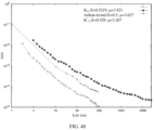
- FIG. 40 and FIG. 41 are schematic diagrams of a comparison of performance and complexity of a (1024, 512) polar subcode by using a kernel K 32 , a kernel K′ 32 , and an Arikan kernel;
- FIG. 42 and FIG. 43 are schematic diagrams of a comparison between a polar code and a 5G LDPC code in terms of performance and complexity;
- FIG. 44 is a schematic block diagram of an apparatus according to at least one embodiment
- FIG. 45 is a schematic diagram of a structure of an apparatus according to at least one embodiment.
- FIG. 46 is still another schematic diagram of a structure of an apparatus according to at least one embodiment.
- the wireless communication system includes but is not limited to a wireless local area network (WLAN) system, a narrow band-internet of things (NB-IoT) system, a 5G system, a new radio (NR) system, a long term evolution (LTE) system, or a communication system after 5G.
- the technical solutions in embodiments described herein are further applied to device to device (D2D) communication, machine to machine (M2M) communication, machine type communication (MTC), satellite communication, and communication in an Internet of Vehicles system. Communication modes in the Internet of Vehicles system are collectively referred to as V2X (X indicates everything).
- the V2X communication includes vehicle to vehicle (V2V) communication, vehicle to infrastructure (V2I) communication, vehicle to pedestrian (V2P) communication, or vehicle to network (V2N) communication.
- eMBB enhanced mobile broadband
- URLLC ultra reliable low latency communication
- eMTC enhanced massive machine type communication
- the network device is any device having a wireless transceiver function.
- the device includes but is not limited to: an evolved NodeB (eNB), a Radio Network Controller (RNC), a NodeB (NB), a Base Station Controller (BSC), a base transceiver station (BTS), a home base station (for example, a Home evolved NodeB, or a Home NodeB, HNB), a Baseband unit (BBU), an Access Point (AP) in a Wireless Fidelity (Wi-Fi) system, a wireless relay node, a wireless backhaul node, a transmission point (TP), or a transmission and reception point (TRP).
- eNB evolved NodeB
- RNC Radio Network Controller
- NB NodeB
- BSC Base Station Controller
- BTS base transceiver station
- HNB Home NodeB
- BBU Baseband unit
- AP Access Point
- Wi-Fi Wireless Fidelity
- TP transmission point
- TRP transmission and reception point
- the device is 5G, for example, NR, a gNB in a system, a transmission point (TRP or TP), or one or a group of (including a plurality of antenna panels) antenna panels of a base station in the 5G system, or is a network node that forms the gNB or the transmission point, for example, the Baseband unit (BBU) or a distributed unit (DU).
- 5G for example, NR, a gNB in a system, a transmission point (TRP or TP), or one or a group of (including a plurality of antenna panels) antenna panels of a base station in the 5G system, or is a network node that forms the gNB or the transmission point, for example, the Baseband unit (BBU) or a distributed unit (DU).
- BBU Baseband unit
- DU distributed unit
- the gNB includes a central unit (CU) and the DU.
- the gNB further includes an active antenna unit (AAU).
- the CU implements some functions of the gNB, and the DU implements some functions of the gNB.
- the CU is responsible for processing a non-real-time protocol and a service, to implement functions of a radio resource control (RRC) layer and a packet data convergence protocol (PDCP) layer.
- RRC radio resource control
- PDCP packet data convergence protocol
- the DU is responsible for processing a physical layer protocol and a real-time service, and implements functions of a radio link control (RLC) layer, a media access control (MAC) layer, and a physical (PHY) layer.
- RLC radio link control
- MAC media access control
- PHY physical
- the AAU implements some physical layer processing functions, radio frequency processing, and a function related to the active antenna.
- Information at the RRC layer is eventually converted into information at the PHY layer, or is converted from information at the PHY layer. Therefore, in this architecture, higher layer signaling such as RRC layer signaling is also considered as being sent by the DU or sent by the DU and the AAU.
- the network device is a device including one or more of a CU node, a DU node, and an AAU node.
- the CU is a network device in a radio access network (RAN), or is a network device in a core network (CN). This is not limited in embodiments described herein.
- the terminal device in at least one embodiment is also referred to as user equipment (UE), an access terminal, a subscriber unit, a subscriber station, a mobile station, a remote station, a remote terminal, a mobile device, a user terminal, a terminal, a wireless communication device, a user agent, a user apparatus, or the like.
- UE user equipment
- the terminal device in at least one embodiment is a mobile phone, a Pad, a computer with a wireless transceiver function, a virtual reality (VR) terminal device, an augmented reality (AR) terminal device, a wireless terminal in industrial control, a wireless terminal in self driving, a wireless terminal in remote medical, a wireless terminal in a smart grid, or a wireless terminal in transportation security, a wireless terminal in a smart city, a wearable wireless terminal, a wireless terminal in a smart home, and the like.
- Application scenarios are not limited in embodiments described herein.
- FIG. 1 and FIG. 2 For ease of understanding embodiments described herein, a communication system to which an at least one embodiment is applicable is first described in detail with reference to FIG. 1 and FIG. 2 .
- FIG. 1 is a schematic diagram of a wireless communication system applicable to at least one embodiment.
- the wireless communication system includes at least one network device 110 and at least one terminal device (for example, 111 , 112 , and 113 shown in FIG. 1 ).
- the network device 110 performs wireless communication with the terminal device.
- the network device 110 is an encoder, and the terminal device is a decoder.
- the terminal device is an encoder, and the network device is a decoder.
- original information is transmitted through a channel, received by a decoder, and decoded by the decoder to restore the original information.
- the encoder is also referred to as a transmit end (or a sending device), and the decoder is also referred to as a receive end (or a receiving device) of information or data.
- the sending device is a network device, and the receiving device is a terminal device.
- the sending device is a terminal device, and the receiving device is a network device.
- the sending device is a terminal device, and the receiving device is a terminal device.
- the sending device is a network device, and the receiving device is a network device.
- FIG. 1 is merely an example for description, and embodiments described herein not limited thereto.
- at least one embodiment is further applied to any communication scenario of uplink/downlink control channel coding in a 5G eMBB scenario.
- FIG. 2 is a basic flowchart of performing communication by using a wireless technology.
- a signal source at a transmit end is sent on a channel after signal source encoding, channel encoding, rate matching, and modulation in sequence.
- a receive end After receiving the signal, a receive end sequentially performs demodulation, rate de-matching, channel decoding, and signal source decoding to obtain a sink.
- the technical solutions provided in embodiments described herein are applied to a channel encoding module and a channel decoding module shown in a dashed box in FIG. 2 .
- Channel coding is one of core technologies in the wireless communication field, and performance improvement of channel coding directly improves network coverage and a user transmission rate.
- a polar code is strictly proved to be a channel encoding scheme that reaches a channel capacity, and has features such as high performance, low complexity, and a flexible matching manner.
- the polar code is determined by the 3GPP as a control channel coding scheme in a 5G control channel eMBB scenario (uplink/downlink).
- FIG. 3 is a schematic diagram of encoding a polar code.
- a symbol “ ⁇ ” indicates binary summation
- input of the symbol is at a left side and a lower side
- output of the symbol is at a right side.
- Each solid line in FIG. 3 indicates 1 bit.
- ⁇ u 0 , u 1 , u 2 , u 4 ⁇ is set as fixed bits (or frozen bits), and polar encoding is performed on a total of four information bits ⁇ u 3 , u 5 , u 6 , u 7 ⁇ , to obtain eight encoded bits.
- the eight encoded bits are modulated and then sent through a noisy channel.
- To-be-encoded bits are sorted based on their respective reliability. Generally, a bit with high reliability is set to an information bit (data), a bit with low reliability is set to a frozen bit, and a value of the frozen bit is usually set to 0, which is known to both a transmit end and a receive end in actual transmission. As shown in FIG. 3 , u 7 , u 6 , u 5 , and u 3 are four bits with high reliability, and are set as information bits (data). u 4 , u 2 , u 1 , and u 0 are four bits with low reliability, and are set as frozen bits.
- H (i) indicates the i th column of the check matrix H.
- FIG. 4 is a schematic diagram of trellis representation.
- a basic component unit in trellis representation is a trellis node (for example, nodes 1 , 2 , . . . , and 20 in FIG. 4 ).
- a polar code is a constructable channel encoding scheme that reaches a binary input discrete memoryless channel capacity.
- a channel condition transition probability is expressed as W(y
- a capacity of the B-DM channel (B-DMC) W is defined as follows:
- I ⁇ ( W ) ⁇ y ⁇ Y ⁇ x ⁇ ⁇ 0 , 1 ⁇ 1 2 ⁇ W ⁇ ( y ⁇ ⁇ " ⁇ [LeftBracketingBar]" x ) ⁇ log ⁇ W ⁇ ( y ⁇ ⁇ " ⁇ [LeftBracketingBar]” x ) 1 2 ⁇ W ⁇ ( y ⁇ ⁇ " ⁇ [LeftBracketingBar]” 0 ) + 1 2 ⁇ W ⁇ ( y ⁇ ⁇ " ⁇ [LeftBracketingBar]” 1 ) .
- a B-DM channel Bhattacharyya parameter is defined as:
- Theorem 1 Given a B-DM channel W (that is, B-DWC W), for F 2 and any ⁇ 1 ⁇ 2, the following is obtained:
- Theorem 2 For any B-DM channel W (that is, B-DWC W), in response to 0 ⁇ I(W) ⁇ 1 and the following conditions are met, an l ⁇ l-dimensional kernel matrix K has a polarization exponent E(K). The conditions are:
- E(K) indicates the polarization exponent.
- the polarization exponent of the arikan kernel is 1 ⁇ 2.
- the polarization exponent measures a convergence speed of decoding performance, and a larger polarization exponent indicates a faster convergence speed, so that better decoding performance is obtained in response to the code length being short.
- the scaling exponent indicates kernel matrix performance. At least one embodiment focuses on a function of the scaling exponent.
- a kernel matrix of a polar code corresponding to (N, k) is K.
- a code length N meets:
- ⁇ (K) is the scaling exponent
- K[i] indicates the i th line of the matrix
- d H (a,b) indicates a Hamming distance between a vector a and a vector b
- a vector D is defined as a partial distance profile (PDP).
- PDP partial distance profile
- n ⁇ k, and a remaining bit is an information bit.
- y 0 l ) is to be calculated.
- y 0 t ) is obtained through recursion.
- m 1, and a corresponding task is referred to as kernel processing.
- the kernel processing is the following:
- LLR log-likelihood ratio
- u(a) i (u o i ⁇ 1 ,a,u i+1 l-1 ).
- i ⁇ j ⁇ l is of equal probability
- a matrix formed by the last (l ⁇ i+1) lines of the kernel K generates corresponding codewords.
- S 1j is obtained by performing ML decoding on a coset of these codewords
- a coset leader is obtained by multiplying u 0 i ⁇ 1 and a matrix formed by the first i lines of the kernel K.
- H is a subset of G
- g is an element of G
- an Arikan kernel is arithkan kernel
- a definition of a path value (a score of c) is provided in a plurality of manners, for example:
- ⁇ ⁇ ( c , y ) ⁇ - ⁇ " ⁇ [LeftBracketingBar]" S ⁇ ( y ) ⁇ " ⁇ [RightBracketingBar]” , ( - 1 ) c ⁇ sign ⁇ S ⁇ ( y ) 0 otherwise .
- the solution of the foregoing formula is equivalent to searching for a probable codeword in response to the last bit in the coset of codeword (i) being 0 or 1.
- the searching is implemented by executing a Viterbi algorithm in a trellis of the codeword (i) . Assuming that the last bit of the codeword is erased, the corresponding trellis is defined as the i th extended trellis.
- complexity of the Viterbi algorithm is O(2 min(i+1,l-i) ).
- kernel processing complexity during decoding is also considered.
- kernel processing complexity during decoding is also considered.
- a kernel with better performance brings higher decoding complexity. Therefore, comprehensive consideration is to be further considered during kernel matrix construction or selection.
- FIG. 6 is a comparison of performance and complexity of a (4096, 2048) polar subcode in response to different polar kernels K 16 and K′ 16 being used on an encoder side and in response to SCL decoding being used on a decoding side.
- the kernel K 16 and the kernel K′ 16 are shown in FIG. 7 and FIG. 8 .
- ⁇ (K) indicates processing complexity of the kernel K .
- a recursive-based kernel processing algorithm is mainly used as an example for description herein.
- FIG. 9 shows a comparison of performance and complexity in response to a polar subcode (1024, 512) in response to K′ 32 and polar kernel K 32 are used on an encoding side and in response to SCL decoding being used on a decoding side. Kernel K 32 and K′ 32 are shown in FIG. 10 and FIG. 11 .
- K′ 32 brings better performance than using K 32 , but decoding complexity of using K′ 32 is higher, and decoding complexity of using K′ 32 is more than 10 times of decoding complexity of using K 32 .
- the linear block code is decoded by using a trellis-based method
- the polar code is also a linear block code, and is also decoded by using such a method.
- specific decoding steps is shown as follows:
- ⁇ j , s max s ′ ⁇ l ⁇ ( j , s ) ( ⁇ j - 1 , s ′ - ⁇ ⁇ ( S ⁇ ( y i - 1 ) , c j - 1 , s ′ , s ) ) ,
- the Arikan kernel is
- the foregoing method is an ML/MAP algorithm.
- decoding complexity is very high, and is difficult to be accepted.
- embodiments described herein propose that improvement is made on an encoder and/or a decoder, so as to reduce decoding complexity.
- a kernel matrix is selected from a plurality of constructed kernel matrices after comprehensive consideration based on an actual situation, so that both the performance and decoding complexity is considered.
- decoding based on trellis code is used, and the trellis diagram is split. A final trellis optimization path is obtained by processing each split result, so that decoding complexity is reduced.
- FIG. 13 is a schematic block diagram of an encoding method 1300 according to at least one embodiment.
- an encoder device obtains to-be-encoded information bits.
- the information bits is generated internally, or is received from outside. This is not limited herein.
- the adjusting an original kernel matrix includes at least the following two solutions.
- One or more kernel matrices are obtained by adjusting a PD of the original kernel matrix.
- One or more kernel matrices are obtained based on Solution 1, and an appropriate target kernel matrix is selected from the one or more kernel matrices.
- a plurality of kernel matrices whose dimensions are different from a dimension of the original kernel matrix are constructed by adjusting the dimension of the original kernel matrix.
- One or more kernel matrices are obtained based on Solution 2, and an appropriate target kernel matrix is selected from the one or more kernel matrices.
- the adjusting the dimension of the original kernel matrix indicates that the dimension of the kernel matrix is changed by modulating the original kernel matrix. For example, corresponding processing is performed on a line and/or a column of the original kernel matrix, so that a line of the constructed kernel matrix is less than the line of the original kernel matrix, and a column of the constructed kernel matrix is less than the column of the original kernel matrix.
- a plurality of kernel matrices are first constructed, and an appropriate kernel matrix is selected for encoding based on the constructed kernel matrices and an actual communication status.
- performance and decoding complexity are comprehensively considered, so that decoding complexity is reduced by selecting the appropriate kernel matrix used during encoding.
- one or more kernel matrices are constructed by adjusting the original kernel matrix, and an appropriate target kernel matrix is selected from the one or more kernel matrices. Then, a data vector and a Kronecker product of the corresponding constructed target kernel matrix are multiplied to implement encoding. Then, data is transmitted through a channel after passing through a rate matching module and a modulation module.
- FIG. 14 is a schematic block diagram of a decoding method 1400 according to at least one embodiment.
- the first trellis corresponds to the t th decoding stage
- the second trellis corresponds to the (t+i) th decoding stage.
- decoding is performed based on the first trellis
- decoding is performed based on the second trellis.
- decoding is performed based on the first trellis
- decoding is performed based on the (t+1) th decoding stage.
- a result obtained through processing in each decoding stage is denoted as an intermediate result.
- an obtained result is denoted as the intermediate result obtained through decoding performed based on the first trellis.
- the intermediate result includes, for example, a decoding path obtained through decoding performed in the t th decoding stage and a corresponding path measure value.
- a composite branch table (CBT) is used for representation.
- content stored in the CBT includes the corresponding path and the corresponding path value during the decoding.
- Each decoding stage corresponds to one CBT.
- intermediate results obtained in different decoding stages is reused.
- some calculation steps is the same. Therefore, reusing is performed for a plurality of times, so that decoding complexity is greatly reduced, and decoding speed is improved.
- the first trellis and the second trellis are mainly used as examples for description. For each trellis in the plurality of sub-trellises, or in each decoding stage, a determination is made whether an intermediate result of decoding in another decoding stage is reused in the decoding stage.
- each of the plurality of trellises is split into a plurality of sub-trellises.
- the trellis in response to the to-be-decoded sequence being decoded according to a decoding algorithm based on the trellis, the trellis is first split, and the decoding based on a complete trellis is split into decoding based on a sub-trellis, thereby reducing decoding complexity.
- the decoding method provided in at least one embodiment is also denoted as recursive trellis decoding or recursive trellis splitting decoding.
- decoding is performed by using the recursive trellis splitting algorithm proposed in at least one embodiment, so that decoding complexity is low.
- a plurality of kernel matrices is constructed by using Solution 1 and/or Solution 2.
- the appropriate kernel matrix is selected for encoding based on an actual situation.
- a plurality of kernel matrices are constructed by adjusting a PD of an original kernel matrix.
- a plurality of kernel matrices whose dimensions are different from a dimension of the original kernel matrix are constructed by adjusting the dimension of the original kernel matrix.
- a plurality of kernel matrices are constructed by adjusting a PD of an original kernel matrix.
- a plurality of kernel matrices are constructed based on an existing PDP by adjusting the PDP.
- a given PDP is adjusted, and depth-first search is performed based on the adjusted PDP.
- depth-first algorithm Another algorithm similar to the depth-first search algorithm or implements a same function is applicable to at least one embodiment.
- the depth-first algorithm is mainly used as an example for description in the following.
- some constraint conditions in response to the depth-first search being performed, is designed to reduce search space and a quantity of search times.
- the constraint conditions for example, is considered from one or more of the following aspects.
- a constraint condition about a candidate line set M is designed. In other words, the candidate line set meeting a specific condition is limited.
- wt(v 0 t ⁇ 1 ) D i ⁇ .
- a constraint condition on a selected line is designed. In other words, the selected line meeting a specific condition is limited.
- a condition is that in response to the i th line being selected from the bottom in the candidate line set M, a Hamming weight of a selected line v is greater than or equal to D i , that is, wt(v) ⁇ D i .
- the line v from the candidate line set M is selected.
- the operation is able to not be continued, the line v is directly discarded, and a new line from the candidate line set M is selected.
- ⁇ indicates a logical operation, or an exclusive OR logical operation.
- Another condition is that a line belongs to a same coset cannot be selected, or a line belongs to a same coset is not selected again.
- the foregoing constraint condition listed for the candidate line set M and the selected line is merely an example for description, and are not limited thereto.
- the constraint condition in response to another constraint condition for the candidate line set M or the selected line belonging to a variant form of the foregoing constraint condition, is also applicable to at least one embodiment.
- An algorithm procedure includes the following steps.
- Step 1 Adjust a PDP to obtain one or more new PDPs.
- step 1 a given PDP is manually adjusted. For example, during adjustment, the PDP is made to be close to a PDP of an Arikan matrix.
- E(K) indicates a polarization exponent.
- the polarization exponent is used to measure convergence speed of the decoding performance, and a larger polarization exponent indicates a faster convergence speed, so that better decoding performance is obtained even in response to the code length being short.
- ⁇ (K) indicates a scaling exponent, and the scaling exponent indicates kernel matrix performance.
- ⁇ (K) indicates complexity, that is, processing complexity of the kernel K . This is not described in the following.
- Step 2 For each new PDP, perform kernel construction method based on depth-first search.
- One or more new PDPs is obtained by manually adjusting the given PDP.
- kernel matrix construction method in the following based on the depth-first search is performed for each new PDP.
- the algorithm in response to any one of the following conditions being met, the algorithm is stopped or the kernel construction is stopped: in response to an appropriate kernel matrix being found; or after lines of all candidate sets are searched while an algorithm that meets the conditions cannot be found to enable the algorithm to be continued.
- a plurality of constructed kernel matrices is obtained by performing the foregoing steps. Next, a best and most appropriate kernel matrix is selected based on comparing some parameters of these kernel matrices, such as a polarization exponent (for example, E(K)), a scaling exponent (for example ⁇ (K),), and decoding complexity (for example ⁇ (K),) of decoding a codeword encoded based on these kernel matrices.
- a polarization exponent for example, E(K)
- ⁇ (K) scaling exponent
- decoding complexity for example ⁇ (K)
- constraint conditions in the following is further added, for example, the constraint conditions in the foregoing Aspect 1 and Aspect 2, to reduce a quantity of attempts and duration.
- wt ( v 0 l-1 ) D i ⁇ .
- a Hamming weight of a selected line v is greater than or equal to D i , that is, wt(v) ⁇ D i .
- Condition 3 In response to the line v being selected from the candidate line set M, and partial distance calculation is performed on the line v and the constructed line, in response to c ⁇ C K ( ⁇ +1) ⁇ K [ ⁇ ] and wt(c) ⁇ D ⁇ , in this case, no further operation is to be performed, the current v is directly discarded, and a new line is selected from the candidate line set M.
- K a 16 ⁇ 16 kernel K is constructed (that is, the currently constructed kernel is a 16 ⁇ 16 kernel K )
- subsequent calculation of d H (v, K [11], K [12], K [13], K [14], K [15] ) is able to not be continued, and the current v is directly discarded.
- a coset C K ( ⁇ ) ⁇ v is calculated, that is, ⁇ c ⁇ v
- d H (v′, C K ( ⁇ ) ) is to be calculated.
- d H (v′, C K ( ⁇ ) ) d H (v, C K ( ⁇ ) ).
- the line that belongs to the same coset is not selected again.
- Condition 1 to Condition 4 are merely examples for description, and are not limited thereto.
- another constraint condition is further designed, so that a quantity of attempts and duration is reduced.
- the PDP in response to the PDP being adjusted, is adjusted in a direction in which the PDP is close to the PDP of the Arikan matrix. Adjusting the PDP in a direction close to the PDP of the arikan matrix is merely an adjustment manner. This is not limited herein.
- a PDP of the constructed best kernel matrix is not necessarily a PDP which is most close to that of the arikan kernel matrix.
- the kernel matrix in response to the best and most appropriate kernel matrix being selected, the kernel matrix is able to not be selected whose PDP is closest to the PDP of the arikan kernel matrix.
- Solution 1 in detail, and a plurality of kernel matrices is constructed by using Solution 1.
- Solution 2 is described in the following.
- a plurality of kernel matrices whose dimensions are different from a dimension of the original kernel matrix are constructed by adjusting the dimension of the original kernel matrix.
- a plurality of kernel matrices with small dimensions are constructed based on an existing kernel matrix with a large dimension. Encoding is performed based on the kernel matrix whose dimension is small, so that lower decoding complexity is provided while the same performance is ensured.
- the plurality of kernel matrices with small dimensions is constructed based on the existing kernel matrix with a large dimension by using a shortening method.
- Another algorithm that constructs a kernel matrix with a small dimension based on an existing kernel matrix with a dimension, or an algorithm that implements a same function, is applicable to at least one embodiment.
- the shortening algorithm is mainly used as an example for description in the following.
- An algorithm procedure includes the following steps.
- Step 1 Consider an l ⁇ l kernel, that is, determine an original kernel matrix.
- Step 2 Select a column j ⁇ [l].
- Step 3 Add the i th line to all lines with 1 in the j th column, where i is a line corresponding to the last 1 in the column.
- Step 4 Delete the i th line and the j th column to obtain an (l ⁇ 1) ⁇ (l ⁇ 1) kernel K ′. ⁇ (K′) ⁇ (K), that is, decoding complexity corresponding to a kernel with a small dimension is lower.
- the kernel matrix constructed in the foregoing manner has lower decoding complexity, and the (l ⁇ t) ⁇ (l ⁇ t) kernel is obtained by repeating the foregoing manner for t times.
- kernel K 24 uses a kernel K 24 as an example to describe a specific example with reference to FIG. 15 to FIG. 19 .
- an original kernel matrix is the kernel K 24 shown in FIG. 15 .
- a new kernel whose dimension is 20 ⁇ 20 is able to be constructed based on the kernel K 24 .
- a specific process is described in the following. In at least one embodiment, both a line sequence number and a column sequence start from 0.
- a kernel matrix constructed based on the kernel K 24 includes one or more of the following: the kernel K 23 shown in FIG. 16 , the kernel K 22 shown in FIG. 17 , the kernel K 21 shown in FIG. 18 , and the kernel K 20 shown in FIG. 19 .
- an appropriate kernel matrix is selected from the foregoing plurality of kernel matrices based on an actual situation.
- decoding complexity of the kernel matrix obtained by using the foregoing method is lower, for example, ⁇ (K 20 ) ⁇ (K 24 ). Based on this, after comprehensive consideration, for example, performance and complexity, the kernel matrix is selected based on an actual situation.
- a kernel matrix whose dimension is 20 is shown in FIG. 20 to FIG. 22 .
- FIG. 23 a kernel matrix whose dimension is 21 is shown in FIG. 23 and FIG. 24 .
- a kernel matrix whose dimension is 24 is shown in FIG. 25 to FIG. 27 .
- FIG. 28 and FIG. 29 a kernel matrix whose dimension is 25 is shown in FIG. 28 and FIG. 29 .
- a kernel matrix whose dimension is 28 is shown in FIG. 30 .
- a kernel matrix whose dimension is 32 is shown in FIG. 10 .
- the kernel matrices listed in FIG. 20 to FIG. 30 are merely examples for description, and are not limited thereto.
- a plurality of kernel matrices is first constructed, for example, the plurality of kernel matrices are constructed by using Solution 1 and/or Solution 2. Based on the constructed kernel matrices, an appropriate kernel matrix is selected for encoding based on an actual communication situation. In this manner, in response to the kernel matrix being constructed or selected, performance and decoding complexity are comprehensively considered, so that decoding complexity is reduced by selecting the appropriate kernel matrix used during encoding.
- a trellis diagram is first split, and the decoding based on a complete trellis is split into decoding based on a sub-trellis. Then, an optimal path is selected by combining the intermediate results of decoding based on each small trellis diagram.
- a plurality of combinations are obtained after all paths in a trellis of a smaller level are spliced, and an optimal path and a path value of a trellis of a larger level are obtained by selecting a path with a largest score in these combinations.
- An algorithm procedure includes content in the following several aspects.
- Aspect 1 Trellis splitting of a linear block code.
- multi-level splitting is performed on a trellis diagram of each stage t during polar code decoding.
- a linear code C (8, 4) is given, and a generator matrix of the linear code C is
- the path from a moment h to a moment h′ corresponds to the coset p h,h′ , (C)/S h,h′ (C).
- the left figure shows a general trellis diagram of the (8, 4) code
- the right figure shows a splitting trellis diagram of the (8, 4) code.
- the left half part of the left figure and the left half part of the right figure each indicate a path from a moment 0 to a moment 4.
- CBT composite branch table
- the CBT is merely a name for ease of description, and the name does not limit the protection scope of embodiments described herein.
- the CBT includes only two entries is not limited in at least one embodiment. In actual communication, the CBT further includes another entry. This is not limited herein.
- the correlation discrepancy herein indicates a score corresponding to an entry (that is, the path l(D)), and another solution that indicates a score (or a path value) corresponding to the entry is also applicable to at least one embodiment.
- CBT X,y is constructed, and y ⁇ x ⁇ 2. Then, for a specific z (x ⁇ z ⁇ y), CBT x,z and CBT z,y is constructed. For D y ⁇ p x,y (C)/s x,y (C), all cosecs of D′ ⁇ p x,z (C)/s x,z (C) and D′′ ⁇ p z,y (C)/s z,y (C) is enumerated.
- a path [x, y] is truncated into two parts.
- all D y ⁇ p x,y (C)/s x,y (C) are not enumerated, and the CBT x,y is obtained by using the foregoing truncation processing manner. This reduces complexity.
- FIG. 32 to FIG. 34 For ease of understanding, as an example, a process of decoding an (8, 4) Hamming code by using a trellis diagram splitting method is described in FIG. 32 to FIG. 34 .
- the trellis diagram corresponding to a code whose length is 8 is split. As shown in FIG. 32 , the trellis diagram is split into four subcodes whose lengths are 2, and the four subcodes whose lengths are 2 are respectively corresponding to one sub-trellis diagram.
- FIG. 32 shows a corresponding path and a path value calculation process of an [0, 1] segment.
- a corresponding path and the path value of the [0,1] segment is obtained through the following calculation:
- an [0, 3] segment is obtained by combining corresponding paths of the [0, 1] and the [2, 3]. For example, a path with the largest path score is selected as a path of the [0, 3] segment, for example, a part enclosed by dashed lines in FIG. 33 . Similarly, a right [4, 7] segment is also obtained by using a same operation. Finally, an entire part of [0, 7] is obtained by combining the [0, 3] and the [4, 7], for example, is obtained by using a path whose path score is the largest in various combinations of the [0, 3] and the [4, 7], as shown in FIG. 34 .
- an appropriate location of the split point is selected based on an actual situation.
- the location of the split point affects decoding complexity. Take a kernel 24 ⁇ 24 as an example. For a selection of z (z:x ⁇ z ⁇ y):
- splitting is evenly performed.
- z (x+y)/2.
- 715 times of summations and 449 times of comparisons is used.
- splitting is performed according to an optimization algorithm. For example, [0, 24) is divided into [0, 16) and [16, 24), and is further evenly split. In this case, 250 times of summations and 124 times of comparisons is used.
- a location of the split point is selected based on the complexity, for example, some split points is selected, so as to reduce decoding complexity.
- a nested code and a nested generator matrix A nested code and a nested generator matrix.
- s x,y (C) ⁇ p x,y (C), and a generator matrix of p x,y (C) is represented as:
- G x , y ( p ) ( G x , z ( s ) 0 0 G z , y ( s ) G x , y ( 00 ) G x , y ( 10 ) G x , y ( 01 ) G x , y ( 11 ) ) .
- a generator matrix of s x,y (C) is represented as:
- G x , y ( s ) ( G x , z ( s ) 0 0 G z , y ( s ) G x , y ( 00 ) G x , y ( 01 ) ) .
- a and b respectively indicate sequence numbers (which is represented in binary) of corresponding entries in coset D′ ⁇ p x,z (C)/s x,z (C) and the coset D′′ ⁇ s z,y (C)/s z,y (C).
- Complexity of the foregoing calculation is approximately O(2k′ x,y +k′ x,y ). Complexity of this method is related to a splitting policy, that is, how to select a split point z from x, y affects decoding complexity.
- a kernel processing method based on a recursive trellis A kernel processing method based on a recursive trellis.
- ⁇ (c (0) ,y 0 l-1 ), and ⁇ (c (1) ,y 0 l-1 ) are entries of CBT 0,l ( C (i) ), and is obtained through recursion by using the following formula:
- decoding complexity is further simplified through processing in the decoding.
- whether an intermediate result obtained from decoding performed based on a trellis is reused by decoding performed based on another trellis is determined based on a correlation between trellises.
- a decoding result obtained through decoding performed based on the trellis is directly used during the decoding performed based on another trellis.
- a combination CBT of all parts in the polar code decoding stage t is the same as a CBT in t+1 stage. In this case, no calculation is to be performed again in the stage t+1.
- whether a result of each decoding stage is reused is determined based on a code obtained by performing a shortening operation on the linear code C in different decoding stages and/or a code obtained by performing a puncturing operation on the linear code C in different decoding stages.
- a correlation between trellises is determined based on a code obtained by performing a shortening operation on the linear code C in different decoding stages and/or a code obtained by performing a puncturing operation on the linear code C in different decoding stages, so as to determine whether a result of each decoding stage is reused.
- whether the intermediate decoding result is reused is determined by checking a relationship between p x,y (C (t+1) ) and p x,y (C (t) ) and/or a relationship between s x,y (C (t+1) ) and s x,y (C (t) ).
- Manner 1 is used in each stage of polar code decoding. For example, in each stage of polar code decoding, whether the foregoing two cases are met is determined.
- a same value is subtracted from entries of all CBTs, while the processing does not affect a final result.
- specific examples are listed in the following.
- CBT x,y [0] ⁇ e max( CBT x,z [0] ⁇ e+CBT z,y [0] ⁇ e,CBT x,z [1] ⁇ e+CBT z,y [1] ⁇ e )
- CBT x,y [1] ⁇ e max( CBT x,z [0] ⁇ e+CBT z,y [1] ⁇ e,CBT x,z [1] ⁇ e+CBT z,y [0] ⁇ e )
- kernel processing the manner of reducing the calculation amount through some calculation processing is applicable to at least one embodiment.
- the formula CBT x,y [v] ⁇ e is to be replaced with the following formula:
- ⁇ ′, and ⁇ ′′ indicate offsets, that is, ⁇ ′ and ⁇ ′′ are offsets depending on u 0 t ⁇ 1 .
- Example 1 A kernel processing on an Arikan matrix with two iterations.
- FIG. 35 is used as an example. For C (0) ,
- K ( 0 ) ( 1 0 0 0 1 1 0 1 0 0 0 1 1 0 0 0 1 1 1 1 0 ) .
- p 0,4 (C (0) ) is a (4, 4) code and s 0,4 (C (0) ) is a (4, 3) code.
- leaders of a coset p 0,4 (C (0) )/s 0,4 (C (0) ) are (0,0,0,0) and (1,0,0,0).
- p 0,2 (C (0) ) and p 2,4 (C (0) ) are (2, 2) codes
- s 0,2 (C (0) and s 2,4 (C (0) ) are (2, 1) codes.
- CBT 0,2 (0) [max( e 0,0 +e 0,1 ,e 1,0 +e 1,1 ),max( e 1,0 +e 0,1 ,e 0,0 +e 1,1 )]
- CBT 2,4 (0) [max( e 0,2 +e 0,3 ,e 1,2 +e 1,3 ),max( e 1,2 +e 0,3 ,e 0,2 +e 1,3 )]
- CBT 0,4 (0) [max( CBT 0,2 (0) [0]+ CBT 2,4 (0) [0], CBT 0,2 (0) [1]+ CBT 2,4 (0) [1]), max( CBT 0,2 (0) [0]+ CBT 2,4 (0) [1], CBT 0,2 (0) [1]+ CBT 2,4 (0) [0])].
- e i,j ⁇ ( S ( y j ) i ).
- FIG. 36 is used as an example.
- C (1) For C (1) ,
- K ( 1 ) ( 1 0 1 0 1 1 1 1 0 0 0 1 1 1 1 0 ) .
- Vectors (0,0,0,0) and (1,0,1,0) in the coset of the (4, 3) code and the (4, 2) code are considered.
- CBT 0,4 (0) [max( CBT 0,2 (0) [0]+ CBT 2,4 (0) [0], CBT 0,2 (0) [1]+ CBT 2,4 (0) [1])].
- FIG. 37 is used as an example.
- C (2) For C (2) ,
- K ( 2 ) ( 1 1 0 0 1 1 1 1 1 1 0 ) .
- p 0,2 (C (2) ) and p 2,4 (C (2) ) are (2, 1) codes; s 0,2 (C (2) ) and s 2,4 (C (2) ) are (2, 0) codes; p 0,4 (C (2) ) is a (4, 2) code, and s 0,4 (C (2) ) is a (4, 1) code.
- CBT 0,2 (0) [e 0,0 +e 0,1 ,e 1,0 +e 1,1 ]
- CBT 2,4 (0) [e 0,2 +e 0,3 ,e 1,2 +e 1,3 ]
- CBT 0,4 (2) [max( CBT 0,2 (2) [0]+ CBT 2,4 (2) [0], CBT 0,2 (2) [1]+ CBT 2,4 (2) [1]), max( CBT 0,2 (2) [0]+ CBT 2,4 (2) [1], CBT 0,2 (2) [1]+ CBT 2,4 (2) [0])].
- K (3) (1 1 1 1 1).
- CBT 0,4 (3) [CBT 0,2 (2) [0]+ CBT 2,4 (2) [0], CBT 0,2 (2) [1]+ CBT 2,4 (2) [1]].
- kernel processing on an Arikan matrix with two iterations is described above as an example.
- the foregoing specific kernel processing is merely an example for description, and is not strictly limited thereto.
- Example 2 A kernel processing on a high-dimensional kernel matrix.
- SC decoding is used as an example.
- the decoding method based on a recursive trellis is applied to each stage of the SC decoding of the polar code.
- a kernel matrix K 1 is shown in FIG. 38 .
- the polar code is decoded based on the decoding method provided in at least one embodiment.
- FIG. 39 shows a partial recursive trellis diagram corresponding to the kernel.
- the CBT in the stage t+1 is a subset of the CBT in the stage t, and is directly obtained without recalculation.
- the intermediate result of decoding is reused in response to s x,y (C (t+1) ) ⁇ s x,y (C (t) ).
- a previous calculation result is directly reused. This reduces polar decoding complexity.
- Table 1 shows complexity comparison between the decoding algorithm provided in at least one embodiment and a Viterbi decoding algorithm in response to different kernel matrices being used on an encoding side.
- At least one embodiment is used not only in a binary domain, but also in a non-binary domain.
- Table 2 shows complexity comparison between the decoding algorithm provided in at least one embodiment and the Viterbi decoding algorithm in response to different kernel matrices being used in the non-binary domain.
- Reed-Solomon indicates a Reed-Solomon code
- Hermitian indicates Hermitian.
- FIG. 40 and FIG. 41 show a comparison between performance and complexity of decoding on a decoding side in response to a kernel K 32 , a kernel K′ 32 , and an Arikan kernel are used on an encoding side for a polar subcode (1024, 512).
- a vertical coordinate FER indicates a frame error ratio
- a horizontal coordinate in FIG. 40 indicates list size
- a horizontal coordinate in FIG. 41 indicates number of summations and comparisons.
- a line indicating the Arikan kernel intersects with lines indicating the kernel K 32 and the kernel K′ 32 at different FERs.
- FIG. 42 and FIG. 43 show comparison results in terms of performance and complexity between a polar code and a Low-density Parity-check code (LDPC code).
- a horizontal coordinate E b /N 0 indicates an errored bit ratio
- E b indicates signal energy per bit
- No indicates a power spectrum density of noise
- a vertical coordinate FER in FIG. 42 indicates a frame error ratio
- a vertical coordinate in FIG. 43 indicates an average number of operations. From FIG. 42 and FIG. 43 , the polar code has more advantages in both performance and complexity.
- encoding is performed by using the encoding method provided in at least one embodiment, and decoding is performed by using an existing decoding method.
- decoding is performed by using the decoding method provided in at least one embodiment.
- decoding is performed by using the decoding method provided in at least one embodiment.
- encoding (polar code encoding) is implemented by multiplying a data vector and Kronecker products of some matrices (kernel), and decoding is performed at a receive end by using a decoding method based on recursive trellis.
- SC decoding is used as an example for description. This is not limited herein.
- embodiments described herein are further used in decoding methods such as SCL, sequence decoding, and SC-Flip.
- the trellis in response to the to-be-decoded sequence being decoded by using a decoding algorithm based on the trellis, the trellis is first split, and the decoding based on a complete trellis is split into decoding based on a sub-trellis, thereby reducing decoding complexity.
- some calculation steps is the same. Therefore, reusing is performed for a plurality of times, so that decoding complexity is greatly reduced, and decoding speed is improved.
- a plurality of kernel matrices are first constructed, and an appropriate kernel matrix is selected for encoding based on the constructed kernel matrices and an actual communication status.
- performance and decoding complexity are comprehensively considered, so that decoding complexity is reduced by selecting the appropriate kernel matrix used during encoding.
- Embodiments described in this specification is independent solutions, or is combined based on internal logic. All these solutions fall within the protection scope of embodiments described herein.
- the solutions on the encoder and the decoder is used separately, or is used in combination.
- a decoder device for example, a network device or a terminal device
- a component for example, a chip or a circuit
- an encoder device for example, a network device or a terminal device
- a component for example, a chip or a circuit
- function module division is performed on an encoder device or a decoder device based on the foregoing method example.
- each function module is obtained through division corresponding to each function, or two or more functions is integrated in one processing module.
- the integrated module is implemented in a form of hardware, or is implemented in a form of a software functional module.
- division into the modules is an example and is merely logical function division, and is other division in an actual implementation. An example in which each functional module is obtained through division based on each corresponding function is used below for description.
- FIG. 44 is a schematic block diagram of an apparatus according to at least one embodiment.
- An apparatus 4400 includes a transceiver unit 4410 and a processing unit 4420 .
- the transceiver unit 4410 implements a corresponding communication function, and the processing unit 4420 is configured to perform data processing.
- the transceiver unit 4410 is also referred to as a communication interface or a communication unit.
- the apparatus 4400 further includes a storage unit.
- the storage unit is configured to store instructions and/or data.
- the processing unit 4420 reads the instructions and/or data in the storage unit, to enable the apparatus to implement the foregoing method embodiments.
- the apparatus 4400 is configured to perform an action performed by the encoder device in the foregoing method embodiment.
- the apparatus 4400 is the encoder device or the component that is disposed in the encoder device.
- the transceiver unit 4410 is configured to perform operations related to receiving and sending on the encoder device in the foregoing method embodiment.
- the processing unit 4420 is configured to perform processing-related operations on the encoder device in the foregoing method embodiment.
- the apparatus 4400 is configured to perform an action performed by the decoder device in the foregoing method embodiment.
- the apparatus 4400 is the decoder device or the component that is disposed in the decoder device.
- the transceiver unit 4410 is configured to perform operations related to receiving and sending on the decoder device in the foregoing method embodiment.
- the processing unit 4420 is configured to perform processing-related operations on the decoder device in the foregoing method embodiment.
- the apparatus 4400 is configured to perform an action performed by the encoder device in the embodiment shown in FIG. 14 .
- the transceiver unit 4410 is configured to obtain information bits.
- the processing unit 4420 is configured to determine a target kernel matrix, where the target kernel matrix is obtained by adjusting an original kernel matrix.
- the processing unit 4420 is further configured to perform polar encoding on the information bits based on the target kernel matrix.
- a dimension of the target kernel matrix is less than a dimension of the original kernel matrix.
- the target kernel matrix is obtained by adjusting a partial distance of the original kernel matrix.
- the target kernel matrix is obtained by adjusting the partial distance of the original kernel matrix according to a depth-first search algorithm.
- wt(v 0 t ⁇ 1 ) D i ⁇ ; or in response to the i th line being selected from the bottom in the candidate line set M, a Hamming weight of a selected line v is greater than or equal to D i ; or selecting the line v from the candidate line set M and performing partial distance calculation on the line v and a constructed line, where in response to c ⁇ C K ( ⁇ +1) ⁇ K [ ⁇ ], and wt(c) ⁇ D ⁇ , the line v is directly discarded, and a new line from the candidate line set M is selected; or a line that belongs to a same coset is not selected again, where i indicates a line number, i ⁇ [0,l ⁇ 1], wt(v) and wt(
- the original kernel matrix is a kernel matrix K 24 whose dimension is (24 ⁇ 24), and the K 24 is:
- the target kernel matrix is any one of the following:
- the apparatus 4400 implements steps or procedures corresponding to the encoder device in the method embodiments described herein.
- the apparatus 4400 includes units configured to perform the methods performed by the encoder device in the method embodiments in FIG. 13 to FIG. 43 .
- the units in the apparatus 4400 and the foregoing other operations and/or functions are separately used to implement corresponding procedures in the method embodiments in FIG. 13 to FIG. 43 .
- the transceiver unit 4410 is configured to perform Step 1310 in the method 1300
- the processing unit 4420 is configured to perform Step 1320 and step 1330 in the method 1300 .
- the apparatus 4400 is configured to perform an action performed by the decoder device in the embodiment shown in FIG. 14
- the transceiver unit 4410 is configured to obtain a to-be-decoded sequence.
- the processing unit 4420 is configured to decode the to-be-decoded sequence based on a plurality of trellises, and reuse an intermediate result obtained from decoding performed based on a first trellis in the plurality of trellises in response to decoding being performed based on a second trellis in the plurality of trellises, where the first trellis is used for the t th stage of decoding the to-be-decoded sequence, the second trellis is used for the (t+i) th stage of decoding the to-be-decoded sequence, t is an integer greater than 0 or equal to 0, and i is an integer greater than 1 or equal to 1.
- each of the plurality of trellises is split into a plurality of sub-trellises.
- locations of split points of the plurality of sub-trellises are related to decoding complexity.
- the processing unit 4420 is further configured to determine, based on a correlation between the first trellis and the second trellis, whether to reuse the intermediate result obtained through decoding performed based on the first trellis in response to decoding being performed based on the second trellis.
- the processing unit 4420 is configured to determine, based on the following information, whether to reuse the intermediate result obtained through decoding performed based on the first trellis in response to decoding being performed based on the second trellis: a code obtained by performing a shortening operation on a linear code C in the (t+i) th stage of decoding and a code obtained by performing the shortening operation on the linear code C in the t th stage of decoding; and/or a code obtained by performing a puncturing operation on the linear code C in the (t+i) th stage of decoding and a code obtained by performing a puncturing operation on the linear code C in the t th stage of decoding.
- the processing unit 4420 is configured to: directly use the intermediate result obtained through decoding performed based on the first trellis as an intermediate result obtained through decoding performed based on the second trellis in response to processing being performed based on the second trellis in the (t+i) th stage of decoding; or process based on a result of a maximization operation in a process of the first trellis in response to processing being performed based on the second trellis in the (t+i) th stage of decoding.
- the apparatus 4400 implements steps or procedures corresponding to the decoder device in the method embodiments described herein.
- the apparatus 4400 includes units configured to perform the methods performed by the decoder device in the method embodiments in FIG. 13 to FIG. 43 .
- the units in the apparatus 4400 and the foregoing other operations and/or functions are separately used to implement corresponding procedures in the method embodiments in FIG. 13 to FIG. 43 .
- the transceiver unit 4410 is configured to perform Step 1410 in the method 1400
- the processing unit 4420 is configured to perform Step 1420 in the method 1400 .
- the processing unit 4420 in the foregoing embodiment is implemented by at least one processor or a processor-related circuit.
- the transceiver unit 4410 is implemented by using a transceiver or a transceiver-related circuit.
- the transceiver unit 4410 is also referred to as a communication unit or a communication interface.
- the storage unit is implemented by at least one memory.
- the foregoing functions of the apparatus 4400 is implemented by hardware, or is implemented by hardware executing corresponding software.
- the apparatus 4400 includes one or more processors.
- the one or more processors are configured to execute a computer program stored in the memory, so that the apparatus 4400 performs any method embodiment described herein.
- the memory configured to store the computer program is located outside the apparatus 4400 , and the one or more processors are connected to the memory by using a circuit and/or a wire. There is one or more memories.
- the apparatus 4400 further includes one or more memories.
- the apparatus 4400 further includes one or more communication interfaces.
- the one or more communication interfaces is an input output interface or an input output circuit. This is not limited in embodiments described herein.
- the apparatus 4400 is further implemented by using hardware.
- the apparatus 4500 includes a processor 4510 .
- the processor 4510 is coupled to a memory 4520 .
- the memory 4520 is configured to store a computer program or instructions and/or data.
- the processor 4510 is configured to execute the computer program or the instructions and/or the data stored in the memory 4520 , so that the methods in the foregoing method embodiments are performed.
- the apparatus 4500 includes one or more processors 4510 .
- the apparatus 4500 further includes the memory 4520 .
- the apparatus 4500 includes one or more memories 4520 .
- the memory 4520 and the processor 4510 is integrated together, or is disposed separately.
- the apparatus 4500 further includes a transceiver 4530 .
- the transceiver 4530 is configured to receive and/or send a signal.
- the processor 4510 is configured to control the transceiver 4530 to receive and/or send a signal.
- the apparatus 4500 is configured to implement the operations performed by the encoder device in the foregoing method embodiments.
- the processor 4510 is configured to perform a processing-related operation performed by the encoder device in the foregoing method embodiment
- the transceiver 4530 is configured to perform operations related to receiving and sending performed by the encoder device in the foregoing method embodiment.
- the apparatus 4500 is configured to implement the operations performed by the decoder device in the foregoing method embodiments.
- the processor 4510 is configured to perform a processing-related operation performed by the decoder device in the foregoing method embodiment
- the transceiver 4530 is configured to perform operations related to receiving and sending performed by the decoder device in the foregoing method embodiment.
- At least one embodiment further provides an apparatus 4600 .
- the apparatus 4600 is configured to perform the operation performed by the encoder device in the foregoing method embodiment, or the apparatus 4600 is configured to perform the operation performed by the decoder device in the foregoing method embodiment.
- the apparatus 4600 includes an input interface circuit 4610 , a logic circuit 4620 , and an output interface circuit 4630 .
- the apparatus 4600 is configured to perform the operations performed by the decoder device in the foregoing method embodiments.
- the apparatus 4600 is also a device or module that is in the decoder and that is configured to implement channel decoding.
- the apparatus is a channel decoder or a channel decoding circuit.
- the apparatus 4600 is a chip disposed in a receive end.
- the input interface circuit 4610 is configured to obtain a to-be-decoded sequence; the logic circuit 4620 is configured to decode the to-be-decoded sequence according to a decoding algorithm provided in embodiments described herein; and the output interface circuit 4630 is configured to output a decoding result.
- the logic circuit 4620 is configured to obtain a to-be-decoded sequence, and decode the to-be-decoded sequence according to a decoding algorithm provided in at least one embodiment.
- the output interface circuit 4630 outputs a decoding result.
- the apparatus 4600 is configured to perform the operations performed by the encoder device in the foregoing method embodiments.
- the apparatus 4600 is also a device or module configured to implement encoding in the encoder.
- the apparatus is an encoder or an encoding circuit.
- the apparatus 4600 is a chip disposed at a transmit end.
- the input interface circuit 4610 is configured to obtain information bits; the logic circuit 4620 is configured to encode the information bits according to an encoding algorithm provided in at least one embodiment; and the output interface circuit 4630 is configured to output an encoded polar code.
- the logic circuit 4620 is configured to generate information bits, and encode the information bits according to the encoding algorithm provided in at least one embodiment; and the output interface circuit 4630 outputs an encoded polar code.
- the apparatus 4600 is a chip or an integrated circuit.
- the chip is a system on chip (SOC), or is a baseband chip.
- the foregoing mainly uses an example in which the input interface circuit 4610 and the output interface circuit 4630 are separate interface circuits for description. This is not limited.
- the input interface circuit 4610 and the output interface circuit 4630 is integrated into one interface.
- At least one embodiment further provides a computer-readable storage medium.
- the computer-readable storage medium stores computer instructions used to implement the method performed by the encoder device or the method performed by the decoder device in the foregoing method embodiments.
- the computer in response to a computer program being executed by a computer, the computer implements the method performed by the encoder device or the method performed by the decoder device in the foregoing method embodiments.
- At least one embodiment further provides a computer program product including instructions.
- the computer In response to the instructions being executed by a computer, the computer is enabled to implement the method performed by the encoder device or the method performed by the decoder device in the foregoing method embodiments.
- At least one embodiment further provides a chip, including one or more memories and one or more processors.
- the one or more memories are configured to store a computer program
- the one or more processors are configured to invoke the computer program from the one or more memories and run the computer program, so that a device in which the chip is installed performs the method in at least one embodiment.
- At least one embodiment further provides a communication device, including the apparatus 4500 or the apparatus 4600 described above.
- At least one embodiment further provides a communication system.
- the communication system includes the encoder device and the decoder device in the foregoing embodiments.
- the decoder in this specification is a receive end of a signal and/or data.
- a party that sends the signal and/or the data is a transmit end.
- the decoder is a network device (for example, a gNB in 5G) in the communication system, or is a terminal device. This is not limited in the solutions of embodiment described herein.
- the encoder in this specification is a transmit end of a signal and/or data.
- a party that receives the signal and/or the data is the receive end.
- the encoder is a network device (for example, a gNB in 5G) in the communication system, or is a terminal device. This is not limited in the solutions of embodiments described herein.
- the encoder device or the decoder device includes a hardware layer, an operating system layer running above the hardware layer, and an application layer running above the operating system layer.
- the hardware layer includes hardware such as a central processing unit (CPU), a memory management unit (MMU), and a memory (also referred to as a primary memory).
- An operating system at the operating system layer is any one or more computer operating systems that implement service processing through a process, for example, a Linux operating system, a Unix operating system, an Android operating system, an iOS operating system, or a Windows operating system.
- the application layer includes applications such as a browser, an address book, word processing software, and instant messaging software.
- a specific structure of an execution body of a method is not limited in embodiments described herein, provided that a program that records code for the method provided in at least one embodiment is run to perform communication according to the method provided in at least one embodiment.
- the execution body of the method provided in embodiments described herein is performed by an encoder device or a decoder device, or is a function module that invokes and execute a program in the encoder device or the decoder device.
- At least one embodiment is implemented as a method, an apparatus, or a product that uses standard programming and/or engineering technologies.
- product used in this specification covers a computer program that is accessed from any computer-readable component, carrier or medium.
- the computer-readable storage medium is any usable medium accessible by a computer, or a data storage device, such as a server or a data center, integrating one or more usable media.
- the usable medium includes, for example, but is not limited to, various media that stores program code such as a magnetic medium or a magnetic storage device (for example, a floppy disk, a hard disk (for example, a removable hard disk), or a magnetic tape), an optical medium (for example, an optical disc, a compact disc (compact disc, CD), or a digital versatile disc (DVD)), a smart card, and a flash storage device (for example, an erasable programmable read-only memory (EPROM), a card, a stick, or a key drive), or a semiconductor medium (for example, a solid-state disk (SSD), a USB flash drive, a read-only memory (ROM), or a random access memory (RAM)).
- SSD solid-state disk
- USB flash drive for example, a USB flash drive,
- machine-readable media includes but is not limited to a radio channel and various other media that stores, includes, and/or carries instructions and/or data.
- the processor in at least one embodiment described herein is a central processing unit (CPU), or is another general-purpose processor, a digital signal processor (DSP), an application-specific integrated circuit (ASIC), a field programmable gate array (FPGA) or another programmable logic device, a discrete gate or transistor logic device, a discrete hardware component, or the like.
- the general-purpose processor is a microprocessor, or the processor is any conventional processor or the like.
- the memory mentioned in embodiments described herein is a volatile memory or a nonvolatile memory, or includes a volatile memory and a nonvolatile memory.
- the nonvolatile memory is a read-only memory (ROM), a programmable ROM (PROM), an erasable programmable read-only memory (EPROM), an electrically EPROM (EEPROM), or a flash memory.
- the volatile memory is a random access memory (RAM).
- the RAM is used as an external cache.
- the RAM includes the following plurality of forms: a static RAM (SRAM), a dynamic RAM (DRAM), a synchronous DRAM (SDRAM), a double data rate SDRAM (DDR SDRAM), an enhanced SDRAM (ESDRAM), a synchlink DRAM (SLDRAM), and a direct rambus RAM (DR RAM).
- SRAM static RAM
- DRAM dynamic RAM
- SDRAM synchronous DRAM
- DDR SDRAM double data rate SDRAM
- ESDRAM enhanced SDRAM
- SLDRAM synchlink DRAM
- DR RAM direct rambus RAM
- the memory is integrated into the processor.
- the processor being a general-purpose processor, a DSP, an ASIC, an FPGA, another programmable logic device, a discrete gate or a transistor logic device, or a discrete hardware component
- the memory storage module
- the memory described in at least one embodiment aims to include but is not limited to these memories and any memory of another proper type.
- the disclosed apparatuses and methods is implemented in other manners.
- the foregoing apparatus embodiments are only examples.
- division into the foregoing units is only logical function division, and is another division manner during actual implementation.
- a plurality of units or components is combined or integrated into another system, or some features is ignored or not performed.
- the displayed or discussed mutual couplings or direct couplings or communication connections is implemented by using some interfaces.
- the indirect couplings or communication connections between the apparatuses or units is implemented in an electronic form, a mechanical form, or another form.
- function units in embodiments described herein are integrated into one unit, or each of the units exist alone physically, or two or more units are integrated into one unit.
- the computer program product includes one or more computer instructions.
- the computer is a general-purpose computer, a dedicated computer, a computer network, or another programmable apparatus.
- the computer is a personal computer, a server, or a network device.
- the computer instructions is stored in a computer-readable storage medium or is transmitted from a computer-readable storage medium to another computer-readable storage medium.
- the computer instructions is transmitted from a website, computer, server, or data center to another website, computer, server, or data center in a wired (for example, a coaxial cable, an optical fiber, or a digital subscriber line (DSL)) or wireless (for example, infrared, radio, or microwave) manner.
- a wired for example, a coaxial cable, an optical fiber, or a digital subscriber line (DSL)
- wireless for example, infrared, radio, or microwave
Landscapes
- Engineering & Computer Science (AREA)
- Computer Networks & Wireless Communication (AREA)
- Signal Processing (AREA)
- Physics & Mathematics (AREA)
- Probability & Statistics with Applications (AREA)
- Theoretical Computer Science (AREA)
- Error Detection And Correction (AREA)
- Tires In General (AREA)
Abstract
Description
and an n-time Kronecker index F2 ⊗m of the kernel matrix corresponds to a linear code whose code length is N=2m. As for a high-dimensional kernel matrix, researchers have proved that a polarization speed when some well-designed high-dimensional kernel matrices are used to encode the polar code is higher, in other words, decoding performance is better. However, the high-dimensional kernel matrix causes high decoding complexity, and how to reduce decoding complexity is an urgent problem to be resolved.
-
- a candidate line set M meets: M[i]={v0 t−1∈F2 l|wt(v0 t−1)=Di}; or
- in response to the ith line being selected from the bottom in the candidate line set M, a Hamming weight of a selected line v is greater than or equal to Di; or
- selecting the line v from the candidate line set M and performing partial distance calculation on the line v and a constructed line, where in response to c∈C
K (φ+1)⊕K [φ], and wt(c)<Dφ, the line v is directly discarded, and a new line from the candidate line set M is selected; or - a line that belongs to a same coset is not selected again, where
- i indicates a line number, i∈[0,l−1], wt(v) wt(c) and both indicate the Hamming weight,
K indicates a currently constructed kernel matrixK ,K [φ] indicates the qth line of the kernel matrixK , Di and Dφ both indicate the partial distance; CK (φ+1) indicates a code corresponding to the kernel matrixK , and ⊕ indicates a logical operation.
| 1 | 0 | 0 | 0 | 0 | 0 | 0 | 0 | 0 | 0 | 0 | 0 | 0 | 0 | 0 | 0 | 0 | 0 | 0 | 0 | 0 | 0 | 0 | 0 |
| 1 | 0 | 0 | 0 | 0 | 0 | 0 | 0 | 0 | 0 | 0 | 0 | 0 | 0 | 0 | 0 | 1 | 0 | 0 | 0 | 0 | 0 | 0 | 0 |
| 1 | 0 | 0 | 0 | 0 | 0 | 0 | 0 | 1 | 0 | 0 | 0 | 0 | 0 | 0 | 0 | 0 | 0 | 0 | 0 | 0 | 0 | 0 | 0 |
| 1 | 0 | 0 | 0 | 0 | 0 | 0 | 0 | 1 | 0 | 0 | 0 | 0 | 0 | 0 | 0 | 1 | 0 | 0 | 0 | 1 | 0 | 0 | 0 |
| 1 | 0 | 1 | 0 | 0 | 0 | 0 | 0 | 0 | 0 | 0 | 0 | 0 | 0 | 0 | 0 | 0 | 0 | 0 | 0 | 0 | 0 | 0 | 0 |
| 1 | 0 | 1 | 0 | 0 | 0 | 0 | 0 | 1 | 0 | 0 | 0 | 1 | 0 | 0 | 0 | 0 | 0 | 0 | 0 | 0 | 0 | 0 | 0 |
| 1 | 0 | 0 | 0 | 1 | 0 | 0 | 0 | 0 | 0 | 0 | 0 | 0 | 0 | 0 | 0 | 0 | 0 | 0 | 0 | 0 | 0 | 0 | 0 |
| 1 | 0 | 0 | 0 | 1 | 0 | 0 | 0 | 1 | 0 | 1 | 0 | 0 | 0 | 0 | 0 | 0 | 0 | 0 | 0 | 0 | 0 | 0 | 0 |
| 1 | 0 | 1 | 0 | 0 | 0 | 0 | 0 | 1 | 0 | 1 | 0 | 0 | 0 | 0 | 0 | 1 | 0 | 1 | 0 | 0 | 0 | 0 | 0 |
| 1 | 1 | 0 | 0 | 0 | 0 | 0 | 0 | 0 | 0 | 0 | 0 | 0 | 0 | 0 | 0 | 0 | 0 | 0 | 0 | 0 | 0 | 0 | 0 |
| 1 | 1 | 0 | 0 | 0 | 0 | 0 | 0 | 1 | 1 | 0 | 0 | 0 | 0 | 0 | 0 | 0 | 0 | 0 | 0 | 0 | 0 | 0 | 0 |
| 1 | 0 | 1 | 0 | 1 | 0 | 1 | 0 | 0 | 0 | 0 | 0 | 0 | 0 | 0 | 0 | 0 | 0 | 0 | 0 | 0 | 0 | 0 | 0 |
| 1 | 0 | 1 | 0 | 1 | 0 | 1 | 0 | 1 | 1 | 0 | 0 | 0 | 0 | 0 | 0 | 1 | 1 | 0 | 0 | 0 | 0 | 0 | 0 |
| 0 | 1 | 1 | 0 | 1 | 0 | 1 | 0 | 0 | 1 | 1 | 0 | 1 | 0 | 1 | 0 | 0 | 0 | 0 | 0 | 0 | 0 | 0 | 0 |
| 1 | 0 | 1 | 0 | 1 | 0 | 1 | 0 | 1 | 0 | 1 | 0 | 1 | 0 | 1 | 0 | 1 | 0 | 1 | 0 | 1 | 0 | 1 | 0 |
| 1 | 1 | 0 | 0 | 1 | 1 | 0 | 0 | 0 | 0 | 0 | 0 | 0 | 0 | 0 | 0 | 0 | 0 | 0 | 0 | 0 | 0 | 0 | 0 |
| 1 | 1 | 1 | 1 | 0 | 0 | 0 | 0 | 0 | 0 | 0 | 0 | 0 | 0 | 0 | 0 | 0 | 0 | 0 | 0 | 0 | 0 | 0 | 0 |
| 0 | 0 | 1 | 1 | 1 | 1 | 0 | 0 | 1 | 1 | 0 | 0 | 1 | 1 | 0 | 0 | 0 | 0 | 0 | 0 | 0 | 0 | 0 | 0 |
| 1 | 1 | 0 | 0 | 1 | 1 | 0 | 0 | 1 | 1 | 1 | 1 | 0 | 0 | 0 | 0 | 0 | 0 | 0 | 0 | 0 | 0 | 0 | 0 |
| 1 | 1 | 0 | 0 | 1 | 1 | 0 | 0 | 1 | 1 | 0 | 0 | 1 | 1 | 0 | 0 | 1 | 1 | 0 | 0 | 1 | 1 | 0 | 0 |
| 1 | 1 | 1 | 1 | 0 | 0 | 0 | 0 | 1 | 1 | 1 | 1 | 0 | 0 | 0 | 0 | 1 | 1 | 1 | 1 | 0 | 0 | 0 | 0 |
| 1 | 1 | 1 | 1 | 1 | 1 | 1 | 1 | 0 | 0 | 0 | 0 | 0 | 0 | 0 | 0 | 0 | 0 | 0 | 0 | 0 | 0 | 0 | 0 |
| 1 | 1 | 1 | 1 | 1 | 1 | 1 | 1 | 0 | 0 | 0 | 0 | 0 | 0 | 0 | 0 | 1 | 1 | 1 | 1 | 1 | 1 | 1 | 1 |
| 1 | 1 | 1 | 1 | 1 | 1 | 1 | 1 | 1 | 1 | 1 | 1 | 1 | 1 | 1 | 1 | 0 | 0 | 0 | 0 | 0 | 0 | 0 | 0 |
is shown in
3. Channel Parameter
4. Kernel Matrix
and “⊗m” indicates an m-time Kronecker product. Korada and so on prove the conclusion and extend the conclusion to a high-dimensional kernel matrix, and prove that a condition for polarization of any l×l matrix is a permutation matrix of any column in the l×l matrix but not an upper triangular matrix. In addition, Korada and so on also prove that in response to l≤15, a polarization exponent β of any kernel matrix cannot exceed ½. In a case of a same code length, a larger polarization exponent β indicates a lower decoding error probability of a corresponding polar code, and corresponding decoding performance is better. However, a main problem of the high-dimensional kernel matrix polar code is that its decoding algorithm is complex, which is one of bottlenecks in high-dimensional kernel matrix research.
5. Polarization Exponent
P e(n)≤2−n
where A is an information bit set, and a bound of a frame error ratio under SC decoding is:
P e(n)≥2−n
D i □d H,(K[i],
d l-1 □d H(K[l−1],0).
-
- (1) The first l columns of K(i) are obtained by obtaining the last (l−i) lines of K.
- (2) The first line in the last column of K(i) is set to 1, and other lines are set to 0.
is obtained. A trellis corresponding to the Arikan kernel is shown in
11. Correlation Discrepancy
-
- (1) Logarithm of probability, for example, is expressed as: log W(c|y).
- (2) Correlation, for example, is expressed as: Σi(−1)c
i S(yi). S(yi) is the ith LLR. - (3) Correlation discrepancy, for example, is expressed as: Σiτ(S(yi),ci).
is obtained. c(ut)=(u0 t,U(u0 t−1,ut))K, and U(u0 t−1,ut)=ut+1 t−1. The solution of the foregoing formula is equivalent to searching for a probable codeword in response to the last bit in the coset of codeword
-
- (1) Let l(j, s) be a set of all states connected, at a moment j−1, to a state s at a moment j.
- (2) Set cj-1,s′,s to a value on a corresponding connection edge.
- (3) Define a node value as
-
- ε0,0=0.
- (4) LLR is obtained through calculation according to S1 (t)(u0 t−1,y0 t−1)=εt,0−εt,1.
is obtained. A corresponding trellis diagram of the Arikan kernel is shown in
D l-3 =d H(
M[i]={v 0 l-1 ∈F 2 l |wt(v 0 l-1)=D i}.
-
- {circle around (1)}{(0000),(1111)}
- {circle around (2)}{(0011),(1100)}
- {circle around (3)}{(1010),(0101)}
- {circle around (4)}{(0110),(1001)}
is obtained.
and v∈F2 k″x,y.
and v∈F2 k″x,y.
CBT x,y[0]·e=max(CBT x,z[0]·e+CBT z,y[0]·e,CBT x,z[1]·e+CBT z,y[1]·e)
CBT x,y[1]·e=max(CBT x,z[0]·e+CBT z,y[1]·e,CBT x,z[1]·e+CBT z,y[0]·e)
Δ=CBT x,y[0]·e−CBT x,y[1]·e=L x,z
Thus:
Δ=CBT x,y[0]·e−CBT x,y[1]·e=L x,z
L p,q =CBT p,q[0]·e−CBT p,q[1]·e, and a
CBT x,y [v]·e=CBT x,z [v]·e+CBT z,y [v]·e,v∈{0,1}.
CBT 0,2 (0)=[max(e 0,0 +e 0,1 ,e 1,0 +e 1,1),max(e 1,0 +e 0,1 ,e 0,0 +e 1,1)]
CBT 2,4 (0)=[max(e 0,2 +e 0,3 ,e 1,2 +e 1,3),max(e 1,2 +e 0,3 ,e 0,2 +e 1,3)]
CBT 0,4 (0)=[max(CBT 0,2 (0)[0]+CBT 2,4 (0)[0],CBT 0,2 (0)[1]+CBT 2,4 (0)[1]),
max(CBT 0,2 (0)[0]+CBT 2,4 (0)[1],CBT 0,2 (0)[1]+CBT 2,4 (0)[0])].
e i,j=τ(S(y j)i).
CBT 0,4 (0)=[max(CBT 0,2 (0)[0]+CBT 2,4 (0)[0],CBT 0,2 (0)[1]+CBT 2,4 (0)[1])].
CBT 0,2 (0) =[e 0,0 +e 0,1 ,e 1,0 +e 1,1], and CBT 2,4 (0) =[e 0,2 +e 0,3 ,e 1,2 +e 1,3]
CBT 0,4 (2)=[max(CBT 0,2 (2)[0]+CBT 2,4 (2)[0],CBT 0,2 (2)[1]+CBT 2,4 (2)[1]),
max(CBT 0,2 (2)[0]+CBT 2,4 (2)[1],CBT 0,2 (2)[1]+CBT 2,4 (2)[0])].
CBT 0,4 (3) =[CBT 0,2 (2)[0]+CBT 2,4 (2)[0],CBT 0,2 (2)[1]+CBT 2,4 (2)[1]].
| TABLE 1 | |||
| Decoding Algorithm | |||
| Viterbi Decoding Algorithm | in This Embodiment | ||
| Kernel | summation | comparison | summation | comparison |
| K20 | 1189 | 2392 | 497 | 309 |
| K′20 | 3346 | 6714 | 1685 | 1279 |
| K″20 | 7524 | 15054 | 4051 | 3341 |
| K24 | 2102 | 4218 | 715 | 449 |
| K′24 | 4705 | 9424 | 2039 | 1483 |
| K″24 | 10043 | 20100 | 5523 | 4371 |
| K28 | 2865 | 5776 | 1005 | 671 |
| K32 | 4536 | 9072 | 341 | 191 |
| TABLE 2 | |||
| Decoding Algorithm | |||
| Viterbi Decoding Algorithm | in This Embodiment | ||
| Kernel | summation | | summation | comparison | |
| 4 × 4 Reed- | 177 | 232 | 140 | 116 |
| Solomon over GF (22) | ||||
| 8 × 8 Reed- | 66017 | 75440 | 46264 | 45896 |
| Solomon over GF (23) | ||||
| 8 × 8 Hermitian | 2484 | 3304 | 1256 | 1072 |
| over GF (22) | ||||
| 1 | 0 | 0 | 0 | 0 | 0 | 0 | 0 | 0 | 0 | 0 | 0 | 0 | 0 | 0 | 0 | 0 | 0 | 0 | 0 | 0 | 0 | 0 | 0 |
| 1 | 0 | 0 | 0 | 0 | 0 | 0 | 0 | 0 | 0 | 0 | 0 | 0 | 0 | 0 | 0 | 1 | 0 | 0 | 0 | 0 | 0 | 0 | 0 |
| 1 | 0 | 0 | 0 | 0 | 0 | 0 | 0 | 1 | 0 | 0 | 0 | 0 | 0 | 0 | 0 | 0 | 0 | 0 | 0 | 0 | 0 | 0 | 0 |
| 1 | 0 | 0 | 0 | 0 | 0 | 0 | 0 | 1 | 0 | 0 | 0 | 0 | 0 | 0 | 0 | 1 | 0 | 0 | 0 | 1 | 0 | 0 | 0 |
| 1 | 0 | 1 | 0 | 0 | 0 | 0 | 0 | 0 | 0 | 0 | 0 | 0 | 0 | 0 | 0 | 0 | 0 | 0 | 0 | 0 | 0 | 0 | 0 |
| 1 | 0 | 1 | 0 | 0 | 0 | 0 | 0 | 1 | 0 | 0 | 0 | 1 | 0 | 0 | 0 | 0 | 0 | 0 | 0 | 0 | 0 | 0 | 0 |
| 1 | 0 | 0 | 0 | 1 | 0 | 0 | 0 | 0 | 0 | 0 | 0 | 0 | 0 | 0 | 0 | 0 | 0 | 0 | 0 | 0 | 0 | 0 | 0 |
| 1 | 0 | 0 | 0 | 1 | 0 | 0 | 0 | 1 | 0 | 1 | 0 | 0 | 0 | 0 | 0 | 0 | 0 | 0 | 0 | 0 | 0 | 0 | 0 |
| 1 | 0 | 1 | 0 | 0 | 0 | 0 | 0 | 1 | 0 | 1 | 0 | 0 | 0 | 0 | 0 | 1 | 0 | 1 | 0 | 0 | 0 | 0 | 0 |
| 1 | 1 | 0 | 0 | 0 | 0 | 0 | 0 | 0 | 0 | 0 | 0 | 0 | 0 | 0 | 0 | 0 | 0 | 0 | 0 | 0 | 0 | 0 | 0 |
| 1 | 1 | 0 | 0 | 0 | 0 | 0 | 0 | 1 | 1 | 0 | 0 | 0 | 0 | 0 | 0 | 0 | 0 | 0 | 0 | 0 | 0 | 0 | 0 |
| 1 | 0 | 1 | 0 | 1 | 0 | 1 | 0 | 0 | 0 | 0 | 0 | 0 | 0 | 0 | 0 | 0 | 0 | 0 | 0 | 0 | 0 | 0 | 0 |
| 1 | 0 | 1 | 0 | 1 | 0 | 1 | 0 | 1 | 1 | 0 | 0 | 0 | 0 | 0 | 0 | 1 | 1 | 0 | 0 | 0 | 0 | 0 | 0 |
| 0 | 1 | 1 | 0 | 1 | 0 | 1 | 0 | 0 | 1 | 1 | 0 | 1 | 0 | 1 | 0 | 0 | 0 | 0 | 0 | 0 | 0 | 0 | 0 |
| 1 | 0 | 1 | 0 | 1 | 0 | 1 | 0 | 1 | 0 | 1 | 0 | 1 | 0 | 1 | 0 | 1 | 0 | 1 | 0 | 1 | 0 | 1 | 0 |
| 1 | 1 | 0 | 0 | 1 | 1 | 0 | 0 | 0 | 0 | 0 | 0 | 0 | 0 | 0 | 0 | 0 | 0 | 0 | 0 | 0 | 0 | 0 | 0 |
| 1 | 1 | 1 | 1 | 0 | 0 | 0 | 0 | 0 | 0 | 0 | 0 | 0 | 0 | 0 | 0 | 0 | 0 | 0 | 0 | 0 | 0 | 0 | 0 |
| 0 | 0 | 1 | 1 | 1 | 1 | 0 | 0 | 1 | 1 | 0 | 0 | 1 | 1 | 0 | 0 | 0 | 0 | 0 | 0 | 0 | 0 | 0 | 0 |
| 1 | 1 | 0 | 0 | 1 | 1 | 0 | 0 | 1 | 1 | 1 | 1 | 0 | 0 | 0 | 0 | 0 | 0 | 0 | 0 | 0 | 0 | 0 | 0 |
| 1 | 1 | 0 | 0 | 1 | 1 | 0 | 0 | 1 | 1 | 0 | 0 | 1 | 1 | 0 | 0 | 1 | 1 | 0 | 0 | 1 | 1 | 0 | 0 |
| 1 | 1 | 1 | 1 | 0 | 0 | 0 | 0 | 1 | 1 | 1 | 1 | 0 | 0 | 0 | 0 | 1 | 1 | 1 | 1 | 0 | 0 | 0 | 0 |
| 1 | 1 | 1 | 1 | 1 | 1 | 1 | 1 | 0 | 0 | 0 | 0 | 0 | 0 | 0 | 0 | 0 | 0 | 0 | 0 | 0 | 0 | 0 | 0 |
| 1 | 1 | 1 | 1 | 1 | 1 | 1 | 1 | 0 | 0 | 0 | 0 | 0 | 0 | 0 | 0 | 1 | 1 | 1 | 1 | 1 | 1 | 1 | 1 |
| 1 | 1 | 1 | 1 | 1 | 1 | 1 | 1 | 1 | 1 | 1 | 1 | 1 | 1 | 1 | 1 | 0 | 0 | 0 | 0 | 0 | 0 | 0 | 0 |
Claims (10)
Applications Claiming Priority (4)
| Application Number | Priority Date | Filing Date | Title |
|---|---|---|---|
| RU2020130551 | 2020-09-17 | ||
| RURU2020130551 | 2020-09-17 | ||
| RU2020130551 | 2020-09-17 | ||
| PCT/CN2021/115206 WO2022057599A1 (en) | 2020-09-17 | 2021-08-30 | Method and apparatus for encoding polar code, and method and apparatus for decoding polar code |
Related Parent Applications (1)
| Application Number | Title | Priority Date | Filing Date |
|---|---|---|---|
| PCT/CN2021/115206 Continuation WO2022057599A1 (en) | 2020-09-17 | 2021-08-30 | Method and apparatus for encoding polar code, and method and apparatus for decoding polar code |
Publications (2)
| Publication Number | Publication Date |
|---|---|
| US20230223956A1 US20230223956A1 (en) | 2023-07-13 |
| US12113548B2 true US12113548B2 (en) | 2024-10-08 |
Family
ID=80775871
Family Applications (1)
| Application Number | Title | Priority Date | Filing Date |
|---|---|---|---|
| US18/183,272 Active US12113548B2 (en) | 2020-09-17 | 2023-03-14 | Method and apparatus for encoding polar code, and method and apparatus for decoding polar code |
Country Status (4)
| Country | Link |
|---|---|
| US (1) | US12113548B2 (en) |
| EP (1) | EP4199396A4 (en) |
| CN (1) | CN116158031A (en) |
| WO (1) | WO2022057599A1 (en) |
Families Citing this family (1)
| Publication number | Priority date | Publication date | Assignee | Title |
|---|---|---|---|---|
| CN121098333A (en) * | 2024-06-05 | 2025-12-09 | 华为技术有限公司 | A decoding method and decoding device |
Citations (5)
| Publication number | Priority date | Publication date | Assignee | Title |
|---|---|---|---|---|
| CN110868226A (en) * | 2019-11-19 | 2020-03-06 | 武汉理工大学 | Coding and decoding method of polarization code based on mixed polarization kernel |
| CA3113988A1 (en) * | 2018-09-23 | 2020-03-26 | Lg Electronics Inc. | Method for encoding/decoding video signals and apparatus therefor |
| US20200127680A1 (en) | 2018-10-19 | 2020-04-23 | Samsung Electronics Co., Ltd. | Devices for decoding input data by using path metric and decoding methods using the same |
| JP2022513203A (en) * | 2018-12-19 | 2022-02-07 | エルジー エレクトロニクス インコーポレイティド | Video coding method based on secondary conversion and its equipment |
| US20220329786A1 (en) * | 2019-12-31 | 2022-10-13 | Guangdong Oppo Mobile Telecommunications Corp., Ltd. | Transform method and decoder |
Family Cites Families (4)
| Publication number | Priority date | Publication date | Assignee | Title |
|---|---|---|---|---|
| WO2015058416A1 (en) * | 2013-10-26 | 2015-04-30 | 华为技术有限公司 | Polar code decoding method and device |
| US10476998B2 (en) * | 2016-07-11 | 2019-11-12 | Qualcomm Incorporated | Reinforced list decoding |
| EP3656058B1 (en) * | 2017-08-23 | 2022-07-27 | Huawei Technologies Co., Ltd. | Device and method for generating a multi-kernel polar code |
| US11239949B2 (en) * | 2018-02-23 | 2022-02-01 | Huawei Technologies Co., Ltd. | Apparatus and methods for polar code construction and coding |
-
2021
- 2021-08-30 EP EP21868427.2A patent/EP4199396A4/en active Pending
- 2021-08-30 CN CN202180061609.8A patent/CN116158031A/en active Pending
- 2021-08-30 WO PCT/CN2021/115206 patent/WO2022057599A1/en not_active Ceased
-
2023
- 2023-03-14 US US18/183,272 patent/US12113548B2/en active Active
Patent Citations (6)
| Publication number | Priority date | Publication date | Assignee | Title |
|---|---|---|---|---|
| CA3113988A1 (en) * | 2018-09-23 | 2020-03-26 | Lg Electronics Inc. | Method for encoding/decoding video signals and apparatus therefor |
| US20200127680A1 (en) | 2018-10-19 | 2020-04-23 | Samsung Electronics Co., Ltd. | Devices for decoding input data by using path metric and decoding methods using the same |
| JP2022513203A (en) * | 2018-12-19 | 2022-02-07 | エルジー エレクトロニクス インコーポレイティド | Video coding method based on secondary conversion and its equipment |
| CN110868226A (en) * | 2019-11-19 | 2020-03-06 | 武汉理工大学 | Coding and decoding method of polarization code based on mixed polarization kernel |
| CN110868226B (en) * | 2019-11-19 | 2021-09-03 | 武汉理工大学 | Coding and decoding method of polarization code based on mixed polarization kernel |
| US20220329786A1 (en) * | 2019-12-31 | 2022-10-13 | Guangdong Oppo Mobile Telecommunications Corp., Ltd. | Transform method and decoder |
Non-Patent Citations (10)
| Title |
|---|
| Extended European Search Report issued in corresponding European Application No. 21868427.2, dated Jan. 19, 2024, pp. 1-12. |
| G. Trofimiuk and P. Trifonov, Reduced complexity window processing of binary polarization kernels. In Proceedings of IEEE International Symposium on Information Theory, Paris, France, Jul. 2019. |
| Juntan Zhang and Marc P.C. Fossorier. Shuffled iterative decoding. IEEE Transactions on Communications, 53(2), Feb. 2005. |
| Noam Presman, Binary Polarization Kernels from Code Decompositions, Mar. 2015, 22 pages. |
| Satish Babu Korada, Polar Codes: Characterization of Exponent, Bounds, and Constructions, Jan. 2009, 10 pages. |
| Trifonov Peter: "Trellis-based Decoding Techniques for Polar Codeswith Large Kernels",2019 IEEE Information Theory Workshop (ITW), IEEE, Aug. 25, 2019 (Aug. 25, 2019), pp. 1-5, XP033709299. |
| V. Miloslavskaya and P. Trifonov, Sequential decoding of polar codes with arbitrary binary kernel, In Proceedings of IEEE Information Theory Workshop, pp. 377 381, Hobart, Australia, 2014. IEEE. |
| Valerio Bioglio and Ingmar Land. On the marginalization of polarizing kernels. In Proceedings of International Symposium on Turbo Codes and Iterative Information Processing, 2018. |
| Valerio Bioglio et al: "Multi-Kernel Polar Codes: Concept and DesignPrinciples",arxiv.org, Cornell University Library, 201 Olin LibraryCornell University Ithaca, NY 14853, Jan. 14, 2020 (Jan. 14, 2020), XP081578300. |
| Z. Huang, S. Zhang, F. Zhang, C. Duanmu, F. Zhong, and M. Chen. Simplified successive cancellation decoding of polar codes with medium-dimensional binary kernels. IEEE Access, 6:26707-26717, 2018. |
Also Published As
| Publication number | Publication date |
|---|---|
| US20230223956A1 (en) | 2023-07-13 |
| CN116158031A8 (en) | 2024-05-28 |
| EP4199396A4 (en) | 2024-02-21 |
| EP4199396A1 (en) | 2023-06-21 |
| WO2022057599A1 (en) | 2022-03-24 |
| CN116158031A (en) | 2023-05-23 |
Similar Documents
| Publication | Publication Date | Title |
|---|---|---|
| US11750217B2 (en) | Polar coding method and apparatus | |
| US11881870B2 (en) | LDPC code encoding method and communication apparatus | |
| EP4311141A1 (en) | Modulation method, demodulation method, and communication device | |
| EP3996284A1 (en) | Rate matching for polar codes | |
| US11558068B2 (en) | Method and apparatus for encoding polar code concatenated with CRC code | |
| WO2021103978A1 (en) | Polar code encoding method, and device | |
| EP4395182A1 (en) | Encoding method and apparatus, and decoding method and apparatus | |
| EP3879709B1 (en) | Channel encoding method and apparatus based on an encoding neural network | |
| CN110178311A (en) | For using the mixing Chase of polarization code to merge and the technology of incremental redundancy HARQ | |
| US12463746B2 (en) | Encoding and decoding method and apparatus | |
| US12476656B2 (en) | Encoding and decoding method and apparatus | |
| EP3547579A1 (en) | Coding method and device | |
| US11936402B2 (en) | Puncturing of polar codes with complementary sequences | |
| US20240405916A1 (en) | Encoding method and encoding apparatus based on systematic polar code | |
| US12143124B2 (en) | Encoding and decoding method and related apparatus | |
| US12113548B2 (en) | Method and apparatus for encoding polar code, and method and apparatus for decoding polar code | |
| US10211951B2 (en) | Decoding method and apparatus | |
| EP4156522A1 (en) | Rate matching method for ldpc code, and communication device | |
| US20250192919A1 (en) | Rate matching method and communication apparatus | |
| US20250167914A1 (en) | Data processing method, apparatus, and device | |
| US20240405786A1 (en) | Encoding method and encoding apparatus based on polar code | |
| US20190268106A1 (en) | Encoding system for incremental redundancy for hybrid arq for wireless networks | |
| US20240235724A1 (en) | Communication method and apparatus | |
| US20250183919A1 (en) | Data processing method, apparatus, and device | |
| WO2026021126A1 (en) | Method for communication, device, storage medium, and program product |
Legal Events
| Date | Code | Title | Description |
|---|---|---|---|
| FEPP | Fee payment procedure |
Free format text: ENTITY STATUS SET TO UNDISCOUNTED (ORIGINAL EVENT CODE: BIG.); ENTITY STATUS OF PATENT OWNER: LARGE ENTITY |
|
| STPP | Information on status: patent application and granting procedure in general |
Free format text: DOCKETED NEW CASE - READY FOR EXAMINATION |
|
| AS | Assignment |
Owner name: HUAWEI TECHNOLOGIES CO., LTD., CHINA Free format text: ASSIGNMENT OF ASSIGNORS INTEREST;ASSIGNORS:TROFIMIUK, GRIGORII;KARAKCHIEVA, LUDMILA;TRIFONOV, PETER;AND OTHERS;SIGNING DATES FROM 20230601 TO 20230603;REEL/FRAME:064066/0975 |
|
| STPP | Information on status: patent application and granting procedure in general |
Free format text: NON FINAL ACTION MAILED |
|
| STPP | Information on status: patent application and granting procedure in general |
Free format text: RESPONSE TO NON-FINAL OFFICE ACTION ENTERED AND FORWARDED TO EXAMINER |
|
| STPP | Information on status: patent application and granting procedure in general |
Free format text: NOTICE OF ALLOWANCE MAILED -- APPLICATION RECEIVED IN OFFICE OF PUBLICATIONS |
|
| STPP | Information on status: patent application and granting procedure in general |
Free format text: PUBLICATIONS -- ISSUE FEE PAYMENT VERIFIED |
|
| STCF | Information on status: patent grant |
Free format text: PATENTED CASE |
|
| CC | Certificate of correction |