US12109744B2 - Mold for molding system - Google Patents
Mold for molding system Download PDFInfo
- Publication number
- US12109744B2 US12109744B2 US17/587,382 US202217587382A US12109744B2 US 12109744 B2 US12109744 B2 US 12109744B2 US 202217587382 A US202217587382 A US 202217587382A US 12109744 B2 US12109744 B2 US 12109744B2
- Authority
- US
- United States
- Prior art keywords
- injection molding
- mold
- frame
- machine
- cavity
- Prior art date
- Legal status (The legal status is an assumption and is not a legal conclusion. Google has not performed a legal analysis and makes no representation as to the accuracy of the status listed.)
- Active, expires
Links
Images


Classifications
-
- B—PERFORMING OPERATIONS; TRANSPORTING
- B29—WORKING OF PLASTICS; WORKING OF SUBSTANCES IN A PLASTIC STATE IN GENERAL
- B29C—SHAPING OR JOINING OF PLASTICS; SHAPING OF MATERIAL IN A PLASTIC STATE, NOT OTHERWISE PROVIDED FOR; AFTER-TREATMENT OF THE SHAPED PRODUCTS, e.g. REPAIRING
- B29C45/00—Injection moulding, i.e. forcing the required volume of moulding material through a nozzle into a closed mould; Apparatus therefor
- B29C45/03—Injection moulding apparatus
- B29C45/04—Injection moulding apparatus using movable moulds or mould halves
- B29C45/0433—Injection moulding apparatus using movable moulds or mould halves mounted on a conveyor belt or chain
-
- B—PERFORMING OPERATIONS; TRANSPORTING
- B29—WORKING OF PLASTICS; WORKING OF SUBSTANCES IN A PLASTIC STATE IN GENERAL
- B29C—SHAPING OR JOINING OF PLASTICS; SHAPING OF MATERIAL IN A PLASTIC STATE, NOT OTHERWISE PROVIDED FOR; AFTER-TREATMENT OF THE SHAPED PRODUCTS, e.g. REPAIRING
- B29C45/00—Injection moulding, i.e. forcing the required volume of moulding material through a nozzle into a closed mould; Apparatus therefor
- B29C45/17—Component parts, details or accessories; Auxiliary operations
- B29C45/26—Moulds
- B29C45/33—Moulds having transversely, e.g. radially, movable mould parts
Definitions
- the present disclosure related to a mold for injection molding.
- Manufacturing of molded parts by an injection molding machine includes injecting a resin into a mold after clamping the mold, pressing the resin into the mold at a high pressure in order to compensate for a volume decrease due to solidification of the resin, keeping the molded part in the mold until the resin solidifies, and ejecting the molded part from the mold.
- the injection molding process is repeatedly performed to obtain a desired number of molded parts. After a predetermined number of moldings are performed with one mold, the mold is ejected from the injection molding machine, the next mold is setup, the next mold is inserted into the injection molding machine, and then the predetermined number of injection moldings with the next mold is performed.
- FIG. 1 illustrates an injection molding system of US 2018/0009146/Japanese patent publication No. 2018-001738/VN20160002505.
- a mold is moved between a molding operation position where resin is injected and a molded part is taken out, and a cooling position where the resin injected into the mold is cooled.
- Productivity of a system such as the one illustrated on FIG. 1 is typically tied to shortening the time required for conveying the molds as much as possible. What is needed is a way to shorten the mold conveyance time with as little cost increase as possible to the overall injection molding system.
- One exemplary aspect of the present disclosure provides a mold structure that enables shortening the mold conveyance time.
- a mold for injection molding comprising a first member, a second member configured to form a first cavity corresponding to a first molded part by combining the second member with the first member, and wherein the improvement to the mold includes a third member configured to form a second cavity corresponding to a second molded product by combining the third member with the first member.
- FIG. 1 illustrates an injection molding system
- FIG. 2 is a side view of an injection molding machine.
- FIG. 3 is an end view of a fixed platen.
- FIG. 4 A illustrates a flowchart illustrating a molding process.
- FIG. 4 B illustrates an improvement to the molding process in FIG. 4 A .
- FIG. 5 illustrates an injection molding system according to an exemplary embodiment.
- FIGS. 6 A- 6 B illustrate a state for removing a molded part from one set of molds.
- FIGS. 7 A- 7 B illustrate a state for removing a molded part from another set of molds.
- FIGS. 8 A- 8 B illustrate an internal configuration of a mold.
- FIGS. 1 - 3 illustrate injection molding system 1 of US 2018/0009146/Japanese patent publication No. 2018-001738/VN20160002505 and are being provided herein for information/description purposes only.
- the injection molding system 1 includes an injection molding machine 2 , conveying machines 3 A and 3 B, and a control apparatus 4 .
- the injection molding system 1 manufactures a molded part while alternating a plurality of molds using the conveying machines 3 A and 3 B for the one injection molding machine 2 .
- Two molds, 100 A and 100 B are used.
- the mold 100 A/ 100 B is a pair of a fixed mold 101 and a movable mold 102 , which is opened/closed in relation to the fixed mold 101 .
- the molded part is molded by injecting a molten resin into a cavity formed between the fixed mold 101 and the movable mold 102 .
- Clamping plates 101 a and 102 a are respectively fixed to the fixed mold 101 and the movable mold 102 .
- the clamping plates 101 a and 102 a are used to lock the mold 100 A/ 100 B to a molding operation position 11 (mold clamping position) of the injection molding machine 2 .
- a self-closing unit 103 is provided for maintaining a closed state between the fixed mold 101 and the movable mold 102 .
- the self-closing unit 103 enables preventing the mold 100 A/ 100 B from opening after unloading the mold 100 A/ 100 B from the injection molding machine 2 .
- the self-closing unit 103 maintains the mold 100 A/ 100 B in a closed state using a magnetic force.
- the self-closing unit 103 located at a plurality of locations along opposing surfaces of the fixed mold 101 and the movable mold 102 .
- the self-closing unit 103 is a combination of an element on the side of the fixed mold 101 and an element on the side of the movable mold 102 .
- typically two or more pair are installed for one of the molds 100 A and 100 B.
- a conveying machine 3 A loads and unloads the mold 100 A onto/from the molding operation position 11 of the injection molding machine 2 .
- a conveying machine 3 B loads and unloads the mold 100 B onto/from the molding operation position 11 .
- the conveying machine 3 A, the injection molding machine 2 , and the conveying machine 3 B are arranged to be lined up in this order in the X-axis direction. In other words, the conveying machine 3 A and the conveying machine 3 B are arranged laterally with respect to the injection molding machine 2 to sandwich the injection molding machine 2 in the X-axis direction.
- the conveying machines 3 A and 3 B are arranged to face each other, the conveying machine 3 A is arranged on one side laterally of the injection molding machine 2 , and the conveying machine 3 B is arranged on the other side respectively adjacent.
- the molding operation position 11 is positioned between the conveying machine 3 A and the conveying machine 3 B.
- the conveying machines 3 A and 3 B respectively include a frame 30 , a conveyance unit 31 , a plurality of rollers 32 , and a plurality of rollers 33 .
- the frame 30 is a skeleton of the conveying machine 3 A and 3 B, and supports the conveyance unit 31 , and the pluralities of rollers 32 and 33 .
- the conveyance unit 31 is an apparatus that moves the mold 100 A/ 100 B back and forth in the X-axis direction, and that removes and inserts the mold 100 A/ 100 B in relation to the molding operation position 11 .
- the conveyance unit 31 is an electrically driven cylinder with a motor as a driving source, and includes a rod that moves forward/backward in relation to the cylinder.
- the cylinder is fixed to the frame 30 , and the fixed mold 101 is fixed to the edge portion of the rod.
- a fluid actuator and an electric actuator can be used, where the electric actuator can provide better precision of control of the position or the speed when conveying the mold 100 A/ 100 B.
- the fluid actuator can be an oil hydraulic cylinder, or an air cylinder, for example.
- the electric actuator can, in addition to being an electrically driven cylinder, be a rack-and-pinion mechanism with a motor as the driving source, a ball screw mechanism with a motor as the driving source, or the like.
- the conveyance unit 31 is arranged independently for each of the conveying machines 3 A and 3 B.
- a common support member that supports the molds 100 A and 100 B can be used, and a single common conveyance unit 31 can be arranged for this support member.
- a case where the conveyance unit 31 is arranged independently for each of the conveying machines 3 A and 3 B enables handling cases where a movement strokes differ between the mold 100 A and the mold 100 B when conveying. For example, a case where molds cannot be conveyed simultaneously since the widths of the molds (the width in the X direction) differ or the thickness of the molds (the width in the Y direction) differ.
- the plurality rollers 32 configure a row of rollers arranged in the X-axis direction, where two rows are configured separated in the Y-axis direction.
- the plurality of rollers 32 rotate around the axis of revolution in the Z-axis direction, and guide movement in the X-axis direction of the mold 100 A/ 100 B contacting the side surfaces of the mold 100 A/ 100 B (the side surfaces of the clamping plates 101 a and 102 a ) and supporting the mold 100 A/ 100 B from the side.
- the plurality rollers 33 configure a row of rollers arranged in the X-axis direction, where two rows are configured separated in the Y-axis direction.
- the plurality of rollers 33 rotate around the axis of revolution in the Y direction, and cause movement in the X direction of the mold 100 A/ 100 B to be smooth, supporting the bottom surfaces of the mold 100 A/ 100 B (the bottom surfaces of the clamping plates 101 a and 102 a ) and supporting the mold 100 A/ 100 B from below.
- the control apparatus 4 includes a controller 41 for controlling the injection molding machine 2 , a controller 42 A for controlling the conveying machine 3 A, and a controller 42 B for controlling the conveying machine 3 B.
- Each of the controllers 41 , 42 A and 42 B includes, for example, a processor such as a CPU, a RAM, a ROM, a storage device such as a hard disk, and interfaces connected to sensors or actuators (not illustrated).
- the processor executes programs stored in the storage device. An example of a program (control) that the controller 41 executes is described below.
- the controller 41 is communicably connected with the controllers 42 A and 42 B, and provides instructions related to the conveyance of the mold 100 A/ 100 B to the controllers 42 A and 42 B.
- the controllers 42 A and 42 B if loading and unloading of the mold 100 A/ 100 B terminates, transmit a signal for operation completion to the controller 41 .
- the controllers 42 A and 42 B transmit an emergency stop signal at a time of an abnormal occurrence to the controller 41 .
- a controller is arranged for each of the injection molding machine 2 , the conveying machine 3 A, and the conveying machine 3 B, but one controller can control all three machines.
- the conveying machine 3 A and the conveying machine 3 B can be controlled by a single controller for more reliable and collaborative operation.
- FIG. 2 illustrates a side view of the injection molding machine 2 .
- FIG. 3 illustrates an end view of a fixed platen 61 , and a figure viewing from the arrow direction of the I-I line in FIG. 2 .
- FIG. 4 illustrates a partial perspective view for describing the configuration of a periphery of the molding operation position 11 .
- the injection molding machine 2 includes an injecting apparatus 5 , a clamping apparatus 6 , and a take-out robot 7 for ejecting a molded part.
- the injecting apparatus 5 and the clamping apparatus 6 are arranged on a frame 10 in the Y-axis direction.
- the injecting apparatus 5 includes an injection cylinder 51 that is arranged to extend in the Y-axis direction.
- the injection cylinder 51 includes a heating device (not illustrated) such as a band heater, and melts a resin introduced from a hopper 53 .
- a screw 51 a is integrated into the injection cylinder 51 , and by rotation of the screw 51 a , plasticizing and measuring the resin introduced into the injection cylinder 51 are performed, and by movement in the axial direction (Y-axis direction) of the screw 51 a , it is possible to inject a molten resin from an injection nozzle 52 .
- FIG. 2 an example of a shut-off nozzle as the nozzle 52 is illustrated.
- a pin 56 a for opening/closing the discharge port 52 a is arranged.
- the pin 56 a is connected with an actuator (a cylinder) 56 c via a link 56 b , and by the operation of the actuator 56 c the discharge port 52 a is opened and closed.
- the injection cylinder 51 is supported by a driving unit 54 .
- a motor for plasticizing and measuring the resin by rotationally drive the screw 51 a and a motor for driving the screw 51 a to move forward/backward in the axial direction are arranged.
- the driving unit 54 can move forward/backward in the Y-axis direction along a rail 12 on the frame 10 , and in the driving unit 54 , an actuator (for example, an electrically driven cylinder) 55 for causing the injecting apparatus 5 to move forward/backward in the Y-axis direction is arranged.
- the clamping apparatus 6 performs a clamping and opening and closing of the molds 100 A/ 100 B.
- the following are arranged in order in the Y-axis direction: the fixed platen 61 , a movable platen 62 , and a movable platen 63 .
- a plurality of tie-bars 64 pass.
- Each of the tie-bars 64 is an axis that extends in the Y-axis direction, one end of which is fixed to the fixed platen 61 .
- Each of the tie-bars 64 is inserted into a respective through hole formed in the movable platen 62 .
- each of the tie-bars 64 is fixed to the movable platen 63 through an adjusting mechanism 67 .
- the movable platens 62 and 63 can move in the Y-axis direction along a rail 13 on the frame 10 , and the fixed platen 61 is fixed to the frame 10 .
- a toggle mechanism 65 is arranged between the movable platen 62 and the movable platen 63 .
- the toggle mechanism 65 causes the movable platen 62 to move forward/backward in the Y-axis direction in relation to the movable platen 63 (in other words, in relation to the fixed platen 61 ).
- the toggle mechanism 65 includes links 65 a to 65 c .
- the link 65 a is connected rotatably to the movable platen 62 .
- the link 65 b is pivotably connected to the movable platen 63 .
- the link 65 a and the link 65 b are pivotably connected to each other.
- the link 65 c and the link 65 b are pivotably connected to each other.
- the link 65 c is pivotably connected to an arm 66 c.
- the arm 66 c is fixed on a ball nut 66 b .
- the ball nut 66 b engages a ball screw shaft 66 a that extends in the Y-axis direction, and moves forward/backward in the Y-axis direction by rotation of the ball screw shaft 66 a .
- the ball screw shaft 66 a is supported such that it is free to rotate by the movable platen 63 , and a motor 66 is supported by the movable platen 63 .
- the motor 66 rotationally drives the ball screw shaft 66 a while the rotation amount of the motor 66 is detected. Driving the motor 66 while detecting the rotation amount of the motor 66 enables clamping, opening, and closing of the mold 100 A/ 100 B.
- the injection molding machine 2 includes sensors 68 for measuring a clamping force, where each sensor 68 is, for example, a strain gauge provided on the tie-bar 64 , and calculates a clamping force by detecting a distortion of the tie-bar 64 .
- the adjusting mechanism 67 includes nuts 67 b supported to freely rotate on the movable platen 63 , motors 67 a as driving sources, and transfer mechanisms for transferring the driving force of the motors 67 a to the nuts 67 b .
- Each of the tie-bars 64 passes through a hole formed in the movable platen 63 , and engages with the nut 67 b .
- the nuts 67 b By causing the nuts 67 b to rotate, the engagement positions in the Y-axis direction between the nuts 67 b and the tie-bars 64 change. That is, the position at which the movable platen 63 is fixed in relation to the tie-bar 64 changes. With this, it is possible to cause a space between the movable platen 63 and the fixed platen 61 to change, and thereby it is possible to adjust a clamping force or the like.
- the molding operation position 11 is a region between the fixed platen 61 and the movable platen 62 .
- the mold 100 A/ 100 B introduced into the molding operation position 11 are sandwiched between the fixed platen 61 and the movable platen 62 and thereby clamped. Opening and closing in based on movement of the movable mold 102 by movement of the movable platen 62 is performed.
- the take-out robot 7 includes a rail 71 that extends in the X-axis direction and a movable rail 72 that can move in the X-axis direction on the rail 71 .
- the movable rail 72 is installed to extend in the Y-axis direction and a slider 73 is provided on the movable rail 72 .
- the slider 73 includes a function for moving in the Y-axis direction guided by the movable rail 72 , and a function of moving an elevating shaft 73 a up and down in the Z-axis direction.
- a vacuum head 74 is provided on the lower end of the elevating shaft 73 a , and a chuck plate 75 specialized to a molded part is mounted on the vacuum head 74 .
- the take-out robot 7 moves the vacuum head 74 between the fixed mold 101 and the movable mold 102 as illustrated by the broken lines in FIG. 2 with the rail 71 , the movable rail 72 , and the slider 73 , vacuums the molded part, and conveys it outside the injection molding machine 2 .
- the take-out robot is a type that grips the molded part mechanically.
- FIG. 3 illustrates an opening portion 61 a in a central portion of the fixed platen 61 through which the nozzle 52 moves forward/backward.
- a plurality of rollers BR are supported such that they are free to rotate.
- the plurality of rollers BR rotate around the axis of revolution in the Y-axis direction, and cause movement in the X-axis direction of the mold 100 A/ 100 B to be smooth, supporting the bottom surfaces (the bottom surface of the clamping plate 101 a ) of the mold 100 A/ 100 B and supporting the mold 100 A/ 100 B from below.
- a roller supporting body 620 is fixed, and the plurality of rollers BR are supported by the roller supporting body 620 .
- grooves 61 b that extend in the X-axis direction are formed.
- the grooves 61 b are formed in two rows separated vertically. On each of the grooves 61 b a roller unit 640 is arranged. For the roller unit 640 , a plurality of rollers SR are supported such that they are free to rotate. The plurality of rollers SR rotate around the axis of revolution in the Z-axis direction, and guide movement in the X-axis direction of the mold 100 A/ 100 B contacting the outer surfaces of the mold 100 A/ 100 B (the outer surface of the clamping plate 101 a ) and supporting the mold 100 A/ 100 B from the side.
- the roller unit 640 can prevent the inner surfaces of the mold 100 A/ 100 B and the fixed platen 61 from contacting and damaging the inner surfaces at a time of alternating the mold 100 A/ 100 B, and the roller unit 640 does not impede the inner surface of the fixed platen 61 and the mold 100 A/ 100 B being closed at a time of clamping.
- a roller supporting body 630 is fixed, and a plurality of rollers SR are supported by the roller supporting body 630 .
- Each fixing mechanism 610 includes an engaging portion 610 a that engages with the clamping plate 101 a , and a built-in actuator (not illustrated) that moves the engaging portion 610 a between an engagement position and an engagement release position.
- a plurality of rollers BR, the roller supporting bodies 620 and 630 , the roller unit 640 , and the fixing mechanism 610 for fixing the movable mold 102 are arranged.
- FIG. 4 A illustrates an example of a known operation of the injection molding system 1 executed by the controller 41 .
- An initial setting is performed in step S 1 .
- the operation conditions of the injecting apparatus 5 and the clamping apparatus 6 are registered for both molds 100 A and 100 B.
- the operation conditions include, but are not limited to, the amount of resin that is injected at one time, the temperature, the injection speed, the clamping force, the initial value of the position of the movable platen 63 in relation to the tie-bars 64 , etc. These operation conditions differ even when the mold 100 A and the mold 100 B are the same type of mold. Because the mold 100 A is used for a first molding operation, the operations conditions related to the mold 100 A are automatically set as the operation conditions. Heating of the injection cylinder 51 and plasticizing and measuring of the resin and the like for the first time is also started.
- step S 2 the mold 100 A is conveyed into the injection molding machine 2 .
- the motor 66 is driven to widen the gap between the fixed platen 61 and the movable platen 62 to slightly wider than the thickness of the mold 100 A (the width in the Y direction).
- the controller 41 transmits an instruction to load the mold 100 A to the controller 42 A, and the controller 42 A drives the conveyance unit 31 to load the mold 100 A into the molding operation position 11 .
- the mold 100 A is unloaded and the mold 100 B loaded at the same time.
- a signal indicating load completion is transmitted from the controller 42 A to the controller 41 .
- the motor 66 When the signal indicating load completion is received, the motor 66 is driven to bring the fixed platen 61 and the movable platen 62 into close contact with the mold 100 A. At this time it is not necessary to generate a clamping force as it is generated to occur during a molding.
- the mold 100 A is locked to each of the fixed platen 61 and the movable platen 62 by driving the fixing mechanisms 610 .
- step S 3 clamping of the mold 100 A by the fixed platen 61 and the movable platen 62 is performed by driving the motor 66 to drive the toggle mechanism 65 . Preparation for injection in relation to the mold 100 A is performed.
- the actuator 55 is driven to move the injecting apparatus 5 , causing the nozzle 52 to contact the mold 100 A.
- step S 5 injection and dwelling of molten resin is performed. More specifically, the injecting apparatus 5 is driven to fill molten resin into a cavity in the mold 100 A from the nozzle 52 , and to press the resin in the cylinder 51 into the mold 100 A at a high pressure in order to compensate for a volume decrease due to the resin solidifying.
- the actual clamping force is measured by the sensor 68 .
- the mold 100 A thermally expands due to the temperature of the mold 100 A gradually rising, and there are cases where a difference arises in the initial clamping force and the clamping force after some time has passed. Thus, it is possible to correct the clamping force at the time of the next clamping based on a result of measurement by the sensors 68 .
- the adjustment of the clamping force is performed by an adjustment of the position of the movable platen 63 in relation to the tie-bar 64 by driving the motor 67 .
- This enables enhancing precision of the clamping force by adjusting the clamping force by correcting the initial value of the position of the movable platen 63 in relation to the tie-bars 64 based on the result of measurement by the sensors 68 .
- the adjustment of the position of the movable platen 63 in relation to the tie-bars 64 can be performed at any timing, e.g., at the timing of steps S 7 and S 9 in FIG. 4 A and steps S 13 -step S 15 in FIG. 4 B .
- step S 6 and step S 8 The processing of step S 6 and step S 8 is performed in parallel to step S 7 .
- step S 6 the timing of the cooling time for the molded part in the mold 100 A is started.
- step S 7 processing related to the clamping apparatus 6 is performed. More specifically, locking of the mold 100 A by the fixing mechanism 610 is released. After a delay of a predetermined time from step S 5 , the motor 66 is driven to drive the toggle mechanism 65 . This results in removal of the clamping force, the movable platen 62 separates slightly in relation to the fixed platen 61 , and a space facilitating alternating the molds is formed.
- step S 8 processing related to the injecting apparatus 5 is performed. For example, a dwelling suck back, a nozzle shut-off, a retraction of the injecting apparatus 5 or the like are performed. The dwelling suck back and the nozzle shut-off prevent the molten resin from dripping when the nozzle 52 separates from the mold 100 A. These processes can be performed during a delay time prior to causing the movable platen 62 to separate slightly in relation to the fixed platen 61 in step S 7 .
- the dwelling suck back reduces the resin pressure in the injection cylinder 51 and in the molds 100 A/ 100 B when, after the dwelling, the screw 51 a is retracted.
- the position to which the screw 51 a is retracted in the dwelling suck back can be managed as an absolute position, and can be managed as a relative position in relation to a position of the screw 51 a after dwelling completion.
- the screw 51 a can be caused to retract until it is detected that the resin pressure measured by a load cell (not illustrated) installed in the injecting apparatus 5 is reduced to a predetermined pressure.
- the nozzle shut-off closes the discharge port 52 a of the nozzle 52 , and in the example of FIG. 2 , the pin 56 a closes the discharge port 52 a .
- This operation enables suppressing the leaking of resin.
- the precision of the measuring of the resin can be improved for the next injection.
- the foregoing processing provides to prevent the resin from leaking, but there are cases where long threadlike resin is generated between the mold 100 A/ 100 B and the nozzle 52 due to the structure of the mold 100 A/ 100 B or the type of resin.
- An apparatus for injecting air into the nozzle 52 can be installed to prevent this from occurring.
- step S 9 alternation of the molds 100 A/ 100 B is performed.
- the mold 100 A is unloaded from the molding operation position 11 to the conveying machine 3 A, and the mold 100 B is loaded from the conveying device 3 B to the molding operation position 11 .
- the controller 41 transmits an instruction to unload the mold 100 A to the controller 42 A, and the controller 42 A drives the conveyance unit 31 to unload the mold 100 A from the molding operation position 11 .
- a signal indicating unloading completion is transmitted from the controller 42 A to the controller 41 .
- the mold 100 A is cooled on the conveying machine 3 A. At this time, the closed state of the mold 100 A is maintained due to the operation of the self-closing unit 103 .
- the operation conditions for the mold 100 B are set as the operation conditions of the molding operation in step S 10 .
- the thickness of the mold 100 B (the width of the Y direction), the clamping force and the like are set as the operation conditions of the molding operation. Molding conditions such as injection speed, etc. corresponding to the mold 100 B are also set. Measurement of plasticization for the next injection is started.
- the motor 66 is driven to cause the fixed platen 61 and the movable platen 62 to closely contact the mold 100 B. At this time, it is not necessary to cause a clamping force as is caused to occur during molding to occur.
- the mold 100 B is locked to both the fixed platen 61 and the movable platen 62 by driving the fixing mechanism 610 .
- step S 10 is performed.
- the molding operation conditions can, for example, be switched simultaneously to the instruction to unload the mold 100 A.
- step S 11 it is determined whether the molding operation is the first molding operation in relation to the molds 100 A and 100 B. If the molding operation is the first molding operation, the process returns to step S 3 . If the molding operation is not the first molding operation, i.e., a second, third, etc. molding operation, the process proceeds to step S 12 .
- step S 3 The processing of step S 3 to step S 8 is then executed for the mold 100 B.
- step S 3 to step S 8 After the processing of step S 3 to step S 8 is executed for the mold 100 B, the mold 100 B is unloaded in step S 9 , and loading of the mold 100 A is performed. The mold 100 B is cooled on the conveying device 3 B. In step S 11 , it is determined that the molding operation is not the first molding operation, and the process proceeds to step S 12 .
- step S 12 it is determined whether the cooling of the mold 100 A has been completed based on whether the cooling time from the start of the time measurement in step S 6 has reached a predetermined time. If cooling has been completed, the processing of step S 13 to step S 16 in FIG. 4 B is performed.
- step S 13 the movable platen 62 is separated from the fixed platen 61 by driving the motor 66 .
- the fixed mold 101 is fixed to the fixed platen 61 by the fixing mechanisms 610
- the movable mold 102 is fixed to the movable platen 62 by the fixing mechanisms 610 . Therefore, the movable mold 102 separates from the fixed mold 101 and the mold 100 A is opened against a force of the self-closing unit 103 .
- step S 14 the molded part remaining on the side of the movable mold 102 of the mold 100 A is removed by driving the take-out robot 7 , and conveyed out of the injection molding machine 2 .
- the vacuum head 74 is moved to a position where the chuck plate 75 faces the molded par, and the molded part is secured by a suction force.
- step S 15 the movable platen 62 is brought close to the fixed platen 61 by driving the motor 66 .
- the movable mold 102 which was previously separated from the fixed mold 101 , closely contacts with the fixed mold 101 , and the mold 100 A is closed.
- steps S 13 , S 14 , and S 15 are executed to remove molded parts from the mold 100 B.
- step S 16 the controller 41 compares the number of currently produced molded parts and a threshold value TH.
- the number of currently produced molded parts is stored in ROM and/or RAM.
- the threshold value TH is the desired production quantity and is set in step S 1 . If the number of currently molded parts is less than the threshold value TH, the flow returns to step S 3 . At that point, the above processing repeats.
- step S 17 the flow proceeds to step S 17 .
- the processing in steps S 17 to S 21 is for removing the molded parts from the other mold, e.g., mold 100 B.
- step S 17 the molds 100 A/ 100 B are alternated in the same manner described in step S 9 .
- the mold 100 A is unloaded from the molding operation position 11 to the conveying machine 3 A, while the mold 100 B is loaded from the conveying device 3 B to the molding operation position 11 .
- the controller 41 transmits an instruction to unload the mold 100 A to the controller 42 A, and the controller 42 A drives the conveyance unit 31 to unload the mold 100 A from the molding operation position 11 .
- a signal indicating unloading completion is transmitted from the controller 42 A to the controller 41 .
- step S 18 After receipt of the signal indicating unloading completion, in step S 18 , it is determined whether cooling of the mold 100 B has been completed based on whether the cooling time started in step S 6 has reached a predetermined time. If the cooling has completed, the process proceeds to step S 19 .
- step S 19 the movable platen 62 is separated from the fixed platen 61 by driving the motor 66 .
- the fixed mold 101 is fixed to the fixed platen 61 by the fixing mechanisms 610
- the movable mold 102 is fixed to the movable platen 62 by the fixing mechanisms 610 .
- the movable mold 102 separates from the fixed mold 101 , and the mold 100 A is opened against the force of the self-closing unit 103 .
- the molded part remaining on the side of the movable mold 102 of the mold 100 A is removed by driving the take-out robot 7 in step S 20 , and conveyed outside the injection molding machine 2 .
- step S 21 the movable platen 62 is brought close to the fixed platen 61 by driving the motor 66 .
- the movable mold 102 which was previously separated from the fixed mold 101 , closely contacts with the fixed mold 101 , and the mold 100 A is closed.
- steps S 19 , S 20 , and S 21 are executed to remove molded parts from the mold 100 B.
- cooling of the molds 100 A and 100 B is performed on the conveying machines 3 A and 3 B outside the injection molding machine 2 .
- each process of molded part removal ⁇ mold clamping ⁇ injection and dwelling is performed by the injection molding machine 2 for the other mold 100 A/ 100 B. Since opening and molded part removal are performed by the injection molding machine 2 , the conveying machines 3 A and 3 B do not need to have functions for opening and molded part removal. Thus, it is possible to manufacture a molded part while alternating the molds 100 A and 100 B with the one injection molding machine 2 while suppressing cost increase of the injection molding system.
- productivity compared to normal molding is improved by at least two times. That is, in addition to suppressing cost increases, higher productivity can be achieved.
- the cooling time of the molds 100 A and 100 B cover 50% or more of the total molding process (the time for one molding cycle), but this depends on the time for the mold replacement process.
- the cooling process covers the longest time, and it is not uncommon for the time to cool the molds 100 A and 100 B to reach from 50% to 70% in relation to the time for one molding cycle. Therefore, the above-described embodiment is particularly effective in improving productivity of this type of molded part.
- the productivity can be particularly improved if the time for the molding cycle of the mold 100 A and the time for the molding cycle of the mold 100 B are approximately the same, while the time for cooling the molds 100 A and 100 B in relation to the time for one molding cycle is greater than or equal to 50%.
- time to cool the molds 100 A and 100 B is less than 50% of the time for one molding cycle, effective application of the time for cooling enables the realization of 1.5 times or 1.8 times higher productivity in relation to normal molding.
- the installation space and the power consumption can be reduced due to achieving the productivity of two injection molding machines by the conventional manufacturing method in the one injection molding machine 2 .
- FIG. 5 , FIGS. 6 A- 6 B , FIGS. 7 A- 7 B , and FIGS. 8 A- 8 B illustrate improvements provided by an exemplary embodiment of the present disclosure over current injection molding systems.
- Components of known injection molding systems are included in the description of Figures FIGS. 5 , FIGS. 6 A- 6 B , FIGS. 7 A- 7 B , and FIGS. 8 A- 8 B for description purposes only and will only be discussed as needed.
- FIG. 5 illustrates an exemplary embodiment of an injection molding system according to the present disclosure.
- the injection molding system 99 includes a horizontal type injection molding machine 2 , conveying machines 3 A and 3 B, and a control device 4 , manufactures molded parts while alternating a plurality of molds by the conveying machines 3 A and 3 B for the injection molding machine 2 .
- Mold 200 includes a fixed mold 101 and movable mold 102 and a movable mold 104 , which are opened and closed with respect to the fixed mold 101 .
- the fixed mold 101 has a long configuration in the X-axis direction, forms a cavity with the movable mold 102 and the movable mold 104 respectively, and molded parts are molded by injecting a molding material, e.g., molten resin, into these cavities.
- a molding material e.g., molten resin
- Clamping plate 101 a and clamping plate 101 b are fixed to the fixed mold 101 .
- Clamping plate 102 a and clamping plate 104 a are fixed to the movable mold 102 and the movable mold 104 , respectively.
- the clamping plates 101 a and 102 a are used to lock the mold 200 A into the molding operation position 11 (mold clamping position) of the injection molding machine 2 .
- the clamping plates 101 b and 104 a are used to lock the mold 200 B into the molding operating position 11 (mold clamping position) of the injection molding machine 2 .
- the conveying machine 3 A carries mold 200 A into and out of the molding operation position 11 of the injection molding machine 2 .
- the conveying machine 3 B carries mold 200 B into and out of the molding operation position 11 of the injection molding machine 2 .
- the conveying machine 3 A and the conveying machine 3 B sandwich the injection molding machine 2 in the X-axis direction.
- the molding operation position 11 is positioned between the conveying machine 3 A and the conveying machine 3 B.
- the components paired with the movable mold 102 and the components paired with the movable mold 104 are integrated to form the single long fixed mold 101 in the X-axis direction.
- the mold 200 A and the mold 200 B can be moved by only one conveyance unit 31 .
- the mold 200 A and the mold 200 B move together. Therefore, the mold 200 B is positioned at a cooling position external to the injection molding machine 2 (the conveying machine 3 B side) when the mold 200 A is positioned at the molding operation position 11 . As illustrated in FIG. 5 , the mold 200 A is positioned at the cooling position external to the injection molding machine 2 (the conveying machine 3 A side) when the mold 200 B is positioned at the molding operation position 11 .
- FIGS. 6 A and 6 B illustrate a state for removing a molded part from mold 200 A.
- a part of the conveying machine 3 A, the conveying machine 3 B, and the injection molding machine 2 is omitted from the figures.
- FIG. 6 A illustrates a state in which the mold 200 A is in the molding operation position 11 and the mold 200 B is in the cooling position.
- the mold 200 B (part of the fixed mold 101 and the movable mold 104 ) is stopped on the frame 10 of the injection molding machine 2 at a position partially inside the injection molding machine 2 .
- the fixed platen 61 adheres closely to the clamping plate 101 a and is fixed with respect to the fixed mold 101 .
- the movable platen 62 comes into close contact with the clamping plate 102 a and is fixed with respect to the movable mold 102 .
- FIG. 6 B illustrates a state in which the movable mold 102 is separated from the fixed mold 101 by moving the movable platen 62 in the direction of the illustrated arrow, and the mold 200 A is opened.
- the fixed mold 101 and the movable mold 102 form a cavity, and a molded part P is molded in this cavity.
- Vacuum head 74 is moved to a position where chuck plate 75 faces the molded part P, and the molded part P is secured by the section force generated by the vacuum head 74 .
- the mold 200 B is stopped at the cooling position as illustrated in FIG. 6 B .
- FIGS. 7 A- 7 B illustrate a state for removing a molded part from mold 200 B.
- a part of the conveying machine 3 A, the conveying machine 3 B, and the injection molding machine 2 is omitted from the figures.
- FIG. 7 A illustrates a state in which the mold 200 B is in the molding operation position 11 and the mold 200 A is in a cooling position.
- the fixed platen 61 adheres closely to the clamping plate 101 a and is fixed with respect to the fixed mold 101 .
- the movable platen 62 comes into close contact with the clamping plate 104 a and is fixed with respect to the movable mold 104 .
- FIG. 7 B illustrates a state in which the movable mold 104 is separated from the fixed mold 101 by moving the movable platen 62 in the direction of the illustrated arrow, and the mold 200 B is opened.
- the fixed mold 101 and the movable mold 104 form a cavity, and a molded part P is molded in this cavity.
- the vacuum head 74 is moved to a position where the chuck plate 75 faces the molded part P, and the molded part P is secured by the suction force generated by the vacuum head 74 .
- the mold 200 A and the mold 200 B alternately move to the molding operation position 11 . Because the fixed mold paired with the movable mold 102 and the fixed mold paired with the movable mold 104 are integrated, the distance between the mold 200 A and the mold 200 B can be shortened. As a result, each cooling position is located on the frame 10 partially inside the injection molding machine 2 .
- the distance between the molding operation position 11 and the cooling position can be shortened in the configuration of the present embodiment compared with the configuration where the molds are independent from each other, i.e., a fixed mold paired with a movable mold and another fixed mold paired with another movable mold are not integrated and are separate bodies. Therefore, the time for moving the mold 100 (time for moving the mold 200 A to the molding operating position 11 and the mold 200 B to the cooling position or the time for moving the mold 200 A to the cooling position and the mold 200 B to the molding operating position 11 ) can be shortened compared with the conventional configuration.
- the cooling position in the present embodiment is closer to the molding operation position 11 , the lengths of the conveying machine 3 A and the conveying machine 3 B in the X-axis direction can be reduced. This enables miniaturization of the injection molding system. In addition, since the lengths of the frame 30 and the like of the conveying machine 3 A and the conveying machine 3 B are also shortened, the material cost for each of these components can also be reduced.
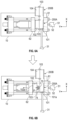
- FIGS. 8 A- 8 B illustrate an internal configuration of mold 200 .
- Mold 200 includes a hot runner (not illustrated), and a heater 105 located internal to the mold 200 as illustrated in FIG. 8 A .
- the heater 105 heats the flow path of the molding material to a cavity, and prevents the molding material from hardening.
- the heater 105 is provided in the mold 200 A and the mold 200 B respectively.
- a heat insulating material 106 is used as illustrated in FIG. 8 A .
- the heat insulating material 106 inserted into a boundary located between the mold 200 A and the mold 200 B.
- an air layer 107 can be formed by partially removing the boundary between the mold 200 A and the mold 200 B as illustrated in FIG. 8 B .
- the inner portion of the mold 200 is removed in consideration of the strength of the fixed mold 101 , so that the mold 200 can be moved.
- spatially relative terms such as “under” “beneath”, “below”, “lower”, “above”, “upper”, “proximal”, “distal”, and the like, may be used herein for ease of description to describe one element or feature's relationship to another element(s) or feature(s) as illustrated in the various figures. It should be understood, however, that the spatially relative terms are intended to encompass different orientations of the device in use or operation in addition to the orientation depicted in the figures. For example, if the device in the figures is turned over, elements described as “below” or “beneath” other elements or features would then be oriented “above” the other elements or features. Thus, a relative spatial term such as “below” can encompass both an orientation of above and below.
- the device may be otherwise oriented (rotated 90 degrees or at other orientations) and the spatially relative descriptors used herein are to be interpreted accordingly. Similarly, the relative spatial terms “proximal” and “distal” may also be interchangeable, where applicable.
- the term “about,” as used herein means, for example, within 10%, within 5%, or less. In some embodiments, the term “about” may mean within measurement error.
- first, second, third, etc. may be used herein to describe various elements, components, regions, parts and/or sections. It should be understood that these elements, components, regions, parts and/or sections should not be limited by these terms. These terms have been used only to distinguish one element, component, region, part, or section from another region, part, or section. Thus, a first element, component, region, part, or section discussed below could be termed a second element, component, region, part, or section without departing from the teachings herein.
Landscapes
- Engineering & Computer Science (AREA)
- Manufacturing & Machinery (AREA)
- Mechanical Engineering (AREA)
- Injection Moulding Of Plastics Or The Like (AREA)
- Moulds For Moulding Plastics Or The Like (AREA)
Abstract
Description
Claims (20)
Priority Applications (2)
| Application Number | Priority Date | Filing Date | Title |
|---|---|---|---|
| US17/587,382 US12109744B2 (en) | 2021-02-09 | 2022-01-28 | Mold for molding system |
| JP2022018034A JP7324324B2 (en) | 2021-02-09 | 2022-02-08 | Injection molding system and method of manufacturing molded articles |
Applications Claiming Priority (2)
| Application Number | Priority Date | Filing Date | Title |
|---|---|---|---|
| US202163147523P | 2021-02-09 | 2021-02-09 | |
| US17/587,382 US12109744B2 (en) | 2021-02-09 | 2022-01-28 | Mold for molding system |
Publications (2)
| Publication Number | Publication Date |
|---|---|
| US20220250293A1 US20220250293A1 (en) | 2022-08-11 |
| US12109744B2 true US12109744B2 (en) | 2024-10-08 |
Family
ID=82703520
Family Applications (1)
| Application Number | Title | Priority Date | Filing Date |
|---|---|---|---|
| US17/587,382 Active 2042-01-28 US12109744B2 (en) | 2021-02-09 | 2022-01-28 | Mold for molding system |
Country Status (2)
| Country | Link |
|---|---|
| US (1) | US12109744B2 (en) |
| JP (1) | JP7324324B2 (en) |
Families Citing this family (1)
| Publication number | Priority date | Publication date | Assignee | Title |
|---|---|---|---|---|
| US20220212380A1 (en) * | 2019-05-17 | 2022-07-07 | Canon Virginia, Inc. | Manufacturing method and an injection molding system |
Citations (9)
| Publication number | Priority date | Publication date | Assignee | Title |
|---|---|---|---|---|
| US4810181A (en) * | 1986-06-19 | 1989-03-07 | Toshiba Kikai Kabushiki Kaisha | Injection molding apparatus with alternately moved metal molds |
| JPH03142208A (en) | 1989-10-30 | 1991-06-18 | Mita Ind Co Ltd | Molding machine |
| JPH0596548A (en) | 1991-03-28 | 1993-04-20 | General Electric Co <Ge> | Multi-layer metal die structure short in cycle time for molding high temperature surface |
| JPH0939036A (en) | 1995-08-01 | 1997-02-10 | Olympus Optical Co Ltd | Injection mold |
| JPH0976288A (en) | 1995-09-08 | 1997-03-25 | Japan Steel Works Ltd:The | Injection molding method and injection molding die |
| US20060172039A1 (en) * | 2005-02-01 | 2006-08-03 | Shoichi Imai | Injection molding system with high production efficiency and low system cost |
| JP2009039876A (en) | 2007-08-06 | 2009-02-26 | Mitsubishi Engineering Plastics Corp | Resin molded body and molding method thereof |
| JP6121601B1 (en) | 2016-07-07 | 2017-04-26 | キヤノンベトナム カンパニー リミテッドCanon Vietnam Co., Ltd. | Manufacturing method and injection molding system |
| WO2020023212A1 (en) * | 2018-07-24 | 2020-01-30 | Canon Virginia, Inc. | Connection for different structures that slide together |
-
2022
- 2022-01-28 US US17/587,382 patent/US12109744B2/en active Active
- 2022-02-08 JP JP2022018034A patent/JP7324324B2/en active Active
Patent Citations (11)
| Publication number | Priority date | Publication date | Assignee | Title |
|---|---|---|---|---|
| US4810181A (en) * | 1986-06-19 | 1989-03-07 | Toshiba Kikai Kabushiki Kaisha | Injection molding apparatus with alternately moved metal molds |
| JPH03142208A (en) | 1989-10-30 | 1991-06-18 | Mita Ind Co Ltd | Molding machine |
| JPH0596548A (en) | 1991-03-28 | 1993-04-20 | General Electric Co <Ge> | Multi-layer metal die structure short in cycle time for molding high temperature surface |
| JPH0939036A (en) | 1995-08-01 | 1997-02-10 | Olympus Optical Co Ltd | Injection mold |
| JPH0976288A (en) | 1995-09-08 | 1997-03-25 | Japan Steel Works Ltd:The | Injection molding method and injection molding die |
| US20060172039A1 (en) * | 2005-02-01 | 2006-08-03 | Shoichi Imai | Injection molding system with high production efficiency and low system cost |
| JP2009039876A (en) | 2007-08-06 | 2009-02-26 | Mitsubishi Engineering Plastics Corp | Resin molded body and molding method thereof |
| JP6121601B1 (en) | 2016-07-07 | 2017-04-26 | キヤノンベトナム カンパニー リミテッドCanon Vietnam Co., Ltd. | Manufacturing method and injection molding system |
| US20180009146A1 (en) * | 2016-07-07 | 2018-01-11 | Canon Vietnam Co., Ltd. | Manufacturing method and injection molding system |
| US11104050B2 (en) | 2016-07-07 | 2021-08-31 | Canon Kabushiki Kaisha | Manufacturing method and injection molding system |
| WO2020023212A1 (en) * | 2018-07-24 | 2020-01-30 | Canon Virginia, Inc. | Connection for different structures that slide together |
Non-Patent Citations (2)
| Title |
|---|
| Nakamura (English Translation of JP2019081346) (Year: 2019). * |
| Nitta, English Translation of JPH0939036A (Year: 1995). * |
Also Published As
| Publication number | Publication date |
|---|---|
| US20220250293A1 (en) | 2022-08-11 |
| JP2022122285A (en) | 2022-08-22 |
| JP7324324B2 (en) | 2023-08-09 |
Similar Documents
| Publication | Publication Date | Title |
|---|---|---|
| US12186953B2 (en) | Manufacturing method and injection molding system | |
| US20230241819A1 (en) | Conveyor device for moving molds | |
| US20220402182A1 (en) | Conveyor device for moving molds | |
| US20240033982A1 (en) | Conveying apparatus for moving molds | |
| WO2020236495A1 (en) | Manufacturing method and injection molding system | |
| US11986984B2 (en) | Injection molding system, conveying apparatus, and mold exchange method | |
| US12109744B2 (en) | Mold for molding system | |
| US12172351B2 (en) | Manufacturing method, injection molding system, and mold | |
| US20220212385A1 (en) | Manufacturing method and injection molding system | |
| US12064906B2 (en) | Manufacturing method and injection molding system | |
| US20220212383A1 (en) | Manufacturing method and injection molding system | |
| US20240253284A1 (en) | Manufacturing method using shuttle mold and overmolding | |
| US12318981B2 (en) | Conveyance apparatus for conveying mold | |
| JP7634981B2 (en) | Method for manufacturing an article and injection molding system | |
| US12005621B2 (en) | Manufacturing method and injection molding system |
Legal Events
| Date | Code | Title | Description |
|---|---|---|---|
| FEPP | Fee payment procedure |
Free format text: ENTITY STATUS SET TO UNDISCOUNTED (ORIGINAL EVENT CODE: BIG.); ENTITY STATUS OF PATENT OWNER: LARGE ENTITY |
|
| STPP | Information on status: patent application and granting procedure in general |
Free format text: DOCKETED NEW CASE - READY FOR EXAMINATION |
|
| STPP | Information on status: patent application and granting procedure in general |
Free format text: NON FINAL ACTION MAILED |
|
| STPP | Information on status: patent application and granting procedure in general |
Free format text: NON FINAL ACTION MAILED |
|
| STPP | Information on status: patent application and granting procedure in general |
Free format text: RESPONSE TO NON-FINAL OFFICE ACTION ENTERED AND FORWARDED TO EXAMINER |
|
| STPP | Information on status: patent application and granting procedure in general |
Free format text: FINAL REJECTION MAILED |
|
| STPP | Information on status: patent application and granting procedure in general |
Free format text: RESPONSE AFTER FINAL ACTION FORWARDED TO EXAMINER |
|
| STPP | Information on status: patent application and granting procedure in general |
Free format text: ADVISORY ACTION MAILED |
|
| STPP | Information on status: patent application and granting procedure in general |
Free format text: DOCKETED NEW CASE - READY FOR EXAMINATION |
|
| AS | Assignment |
Owner name: CANON VIRGINIA, INC., VIRGINIA Free format text: ASSIGNMENT OF ASSIGNORS INTEREST;ASSIGNORS:KODAIRA, KOKI;YANAHARA, YUICHI;SIGNING DATES FROM 20240212 TO 20240215;REEL/FRAME:066560/0064 |
|
| STPP | Information on status: patent application and granting procedure in general |
Free format text: NON FINAL ACTION MAILED |
|
| STPP | Information on status: patent application and granting procedure in general |
Free format text: RESPONSE TO NON-FINAL OFFICE ACTION ENTERED AND FORWARDED TO EXAMINER |
|
| STPP | Information on status: patent application and granting procedure in general |
Free format text: NOTICE OF ALLOWANCE MAILED -- APPLICATION RECEIVED IN OFFICE OF PUBLICATIONS |
|
| STPP | Information on status: patent application and granting procedure in general |
Free format text: PUBLICATIONS -- ISSUE FEE PAYMENT VERIFIED |
|
| STCF | Information on status: patent grant |
Free format text: PATENTED CASE |