US12108872B2 - Pedestal leg assembly - Google Patents
Pedestal leg assembly Download PDFInfo
- Publication number
- US12108872B2 US12108872B2 US17/705,573 US202217705573A US12108872B2 US 12108872 B2 US12108872 B2 US 12108872B2 US 202217705573 A US202217705573 A US 202217705573A US 12108872 B2 US12108872 B2 US 12108872B2
- Authority
- US
- United States
- Prior art keywords
- leg
- pedestal leg
- bolt
- teeth
- release mechanism
- Prior art date
- Legal status (The legal status is an assumption and is not a legal conclusion. Google has not performed a legal analysis and makes no representation as to the accuracy of the status listed.)
- Active, expires
Links
- NJPPVKZQTLUDBO-UHFFFAOYSA-N novaluron Chemical compound C1=C(Cl)C(OC(F)(F)C(OC(F)(F)F)F)=CC=C1NC(=O)NC(=O)C1=C(F)C=CC=C1F NJPPVKZQTLUDBO-UHFFFAOYSA-N 0.000 title claims abstract description 91
- 230000007246 mechanism Effects 0.000 claims abstract description 32
- 238000012546 transfer Methods 0.000 abstract description 13
- 238000004891 communication Methods 0.000 abstract description 3
- 230000000994 depressogenic effect Effects 0.000 description 5
- IUTPYMGCWINGEY-UHFFFAOYSA-N 2,3',4,4',5-Pentachlorobiphenyl Chemical compound C1=C(Cl)C(Cl)=CC=C1C1=CC(Cl)=C(Cl)C=C1Cl IUTPYMGCWINGEY-UHFFFAOYSA-N 0.000 description 4
- 238000012986 modification Methods 0.000 description 3
- 230000004048 modification Effects 0.000 description 3
- 238000000034 method Methods 0.000 description 2
- 230000004075 alteration Effects 0.000 description 1
- 230000007812 deficiency Effects 0.000 description 1
- 239000000383 hazardous chemical Substances 0.000 description 1
- 238000007373 indentation Methods 0.000 description 1
- 239000000463 material Substances 0.000 description 1
- 229910052751 metal Inorganic materials 0.000 description 1
- 239000002184 metal Substances 0.000 description 1
- 150000002739 metals Chemical class 0.000 description 1
- 239000012811 non-conductive material Substances 0.000 description 1
- 238000004382 potting Methods 0.000 description 1
- 238000003825 pressing Methods 0.000 description 1
- 230000008569 process Effects 0.000 description 1
- 230000008707 rearrangement Effects 0.000 description 1
- 230000000717 retained effect Effects 0.000 description 1
- 238000009964 serging Methods 0.000 description 1
- 238000006467 substitution reaction Methods 0.000 description 1
- XLYOFNOQVPJJNP-UHFFFAOYSA-N water Substances O XLYOFNOQVPJJNP-UHFFFAOYSA-N 0.000 description 1
Images


Classifications
-
- A—HUMAN NECESSITIES
- A47—FURNITURE; DOMESTIC ARTICLES OR APPLIANCES; COFFEE MILLS; SPICE MILLS; SUCTION CLEANERS IN GENERAL
- A47B—TABLES; DESKS; OFFICE FURNITURE; CABINETS; DRAWERS; GENERAL DETAILS OF FURNITURE
- A47B13/00—Details of tables or desks
- A47B13/02—Underframes
- A47B13/021—Fastening devices of the feet or legs
-
- A—HUMAN NECESSITIES
- A47—FURNITURE; DOMESTIC ARTICLES OR APPLIANCES; COFFEE MILLS; SPICE MILLS; SUCTION CLEANERS IN GENERAL
- A47B—TABLES; DESKS; OFFICE FURNITURE; CABINETS; DRAWERS; GENERAL DETAILS OF FURNITURE
- A47B13/00—Details of tables or desks
- A47B13/02—Underframes
- A47B13/023—Underframes with a central column
-
- A—HUMAN NECESSITIES
- A47—FURNITURE; DOMESTIC ARTICLES OR APPLIANCES; COFFEE MILLS; SPICE MILLS; SUCTION CLEANERS IN GENERAL
- A47B—TABLES; DESKS; OFFICE FURNITURE; CABINETS; DRAWERS; GENERAL DETAILS OF FURNITURE
- A47B91/00—Feet for furniture in general
- A47B91/08—Feet for furniture in general connected to the floor
-
- B—PERFORMING OPERATIONS; TRANSPORTING
- B60—VEHICLES IN GENERAL
- B60N—SEATS SPECIALLY ADAPTED FOR VEHICLES; VEHICLE PASSENGER ACCOMMODATION NOT OTHERWISE PROVIDED FOR
- B60N3/00—Arrangements or adaptations of other passenger fittings, not otherwise provided for
- B60N3/001—Arrangements or adaptations of other passenger fittings, not otherwise provided for of tables or trays
-
- F—MECHANICAL ENGINEERING; LIGHTING; HEATING; WEAPONS; BLASTING
- F16—ENGINEERING ELEMENTS AND UNITS; GENERAL MEASURES FOR PRODUCING AND MAINTAINING EFFECTIVE FUNCTIONING OF MACHINES OR INSTALLATIONS; THERMAL INSULATION IN GENERAL
- F16B—DEVICES FOR FASTENING OR SECURING CONSTRUCTIONAL ELEMENTS OR MACHINE PARTS TOGETHER, e.g. NAILS, BOLTS, CIRCLIPS, CLAMPS, CLIPS OR WEDGES; JOINTS OR JOINTING
- F16B12/00—Jointing of furniture or the like, e.g. hidden from exterior
- F16B12/40—Joints for furniture tubing
- F16B12/42—Joints for furniture tubing connecting furniture tubing to non-tubular parts
-
- A—HUMAN NECESSITIES
- A47—FURNITURE; DOMESTIC ARTICLES OR APPLIANCES; COFFEE MILLS; SPICE MILLS; SUCTION CLEANERS IN GENERAL
- A47B—TABLES; DESKS; OFFICE FURNITURE; CABINETS; DRAWERS; GENERAL DETAILS OF FURNITURE
- A47B13/00—Details of tables or desks
- A47B13/02—Underframes
- A47B13/06—Underframes of metal
-
- A—HUMAN NECESSITIES
- A47—FURNITURE; DOMESTIC ARTICLES OR APPLIANCES; COFFEE MILLS; SPICE MILLS; SUCTION CLEANERS IN GENERAL
- A47B—TABLES; DESKS; OFFICE FURNITURE; CABINETS; DRAWERS; GENERAL DETAILS OF FURNITURE
- A47B13/00—Details of tables or desks
- A47B13/02—Underframes
- A47B13/021—Fastening devices of the feet or legs
- A47B2013/022—Fastening devices of the feet or legs with detachable connection of a tubular leg
-
- A—HUMAN NECESSITIES
- A47—FURNITURE; DOMESTIC ARTICLES OR APPLIANCES; COFFEE MILLS; SPICE MILLS; SUCTION CLEANERS IN GENERAL
- A47B—TABLES; DESKS; OFFICE FURNITURE; CABINETS; DRAWERS; GENERAL DETAILS OF FURNITURE
- A47B13/00—Details of tables or desks
- A47B13/02—Underframes
- A47B13/023—Underframes with a central column
- A47B2013/024—Underframes with a central column being assembled to a base
-
- A—HUMAN NECESSITIES
- A47—FURNITURE; DOMESTIC ARTICLES OR APPLIANCES; COFFEE MILLS; SPICE MILLS; SUCTION CLEANERS IN GENERAL
- A47B—TABLES; DESKS; OFFICE FURNITURE; CABINETS; DRAWERS; GENERAL DETAILS OF FURNITURE
- A47B2200/00—General construction of tables or desks
- A47B2200/0011—Underframes
- A47B2200/0019—Auxiliary use of table underframes, e.g. incorporating: cooling, drainage, air supply or wires
-
- A—HUMAN NECESSITIES
- A47—FURNITURE; DOMESTIC ARTICLES OR APPLIANCES; COFFEE MILLS; SPICE MILLS; SUCTION CLEANERS IN GENERAL
- A47B—TABLES; DESKS; OFFICE FURNITURE; CABINETS; DRAWERS; GENERAL DETAILS OF FURNITURE
- A47B2200/00—General construction of tables or desks
- A47B2200/0011—Underframes
- A47B2200/002—Legs
- A47B2200/0021—Tables or desks of the single column type
- A47B2200/0022—Central column leg assembly composed of several segments
-
- A—HUMAN NECESSITIES
- A47—FURNITURE; DOMESTIC ARTICLES OR APPLIANCES; COFFEE MILLS; SPICE MILLS; SUCTION CLEANERS IN GENERAL
- A47B—TABLES; DESKS; OFFICE FURNITURE; CABINETS; DRAWERS; GENERAL DETAILS OF FURNITURE
- A47B3/00—Folding or stowable tables
- A47B3/06—Folding or stowable tables with separable parts
-
- H—ELECTRICITY
- H01—ELECTRIC ELEMENTS
- H01R—ELECTRICALLY-CONDUCTIVE CONNECTIONS; STRUCTURAL ASSOCIATIONS OF A PLURALITY OF MUTUALLY-INSULATED ELECTRICAL CONNECTING ELEMENTS; COUPLING DEVICES; CURRENT COLLECTORS
- H01R13/00—Details of coupling devices of the kinds covered by groups H01R12/70 or H01R24/00 - H01R33/00
- H01R13/02—Contact members
- H01R13/22—Contacts for co-operating by abutting
- H01R13/24—Contacts for co-operating by abutting resilient; resiliently-mounted
-
- H—ELECTRICITY
- H01—ELECTRIC ELEMENTS
- H01R—ELECTRICALLY-CONDUCTIVE CONNECTIONS; STRUCTURAL ASSOCIATIONS OF A PLURALITY OF MUTUALLY-INSULATED ELECTRICAL CONNECTING ELEMENTS; COUPLING DEVICES; CURRENT COLLECTORS
- H01R2103/00—Two poles
-
- H—ELECTRICITY
- H01—ELECTRIC ELEMENTS
- H01R—ELECTRICALLY-CONDUCTIVE CONNECTIONS; STRUCTURAL ASSOCIATIONS OF A PLURALITY OF MUTUALLY-INSULATED ELECTRICAL CONNECTING ELEMENTS; COUPLING DEVICES; CURRENT COLLECTORS
- H01R25/00—Coupling parts adapted for simultaneous co-operation with two or more identical counterparts, e.g. for distributing energy to two or more circuits
- H01R25/003—Coupling parts adapted for simultaneous co-operation with two or more identical counterparts, e.g. for distributing energy to two or more circuits the coupling part being secured only to wires or cables
Definitions
- the present invention relates to the field of table and pedestal legs and more specifically to a leg having locking and/or power supply capabilities.
- Removable tables often comprise a table top and one or more removable legs that are fixed into an opening in the floor. The table leg or legs may be locked into openings to support a table top, and removed from openings to create more space as needed.
- locking mechanisms have several drawbacks. For example, many table leg locking mechanisms are difficult to operate or require multiple users to both hold and lock the leg in place. The locking process can be time consuming and onerous. In addition, some locking legs that are screwed into place lack simple mechanisms to prevent unwanted unlocking or removal of the leg from the corresponding opening.
- a pedestal leg assembly is generally provided.
- the pedestal leg assembly may comprise a pedestal leg having a top end, bottom end, and sidewall extending therebetween.
- the leg may include a plurality of teeth positioned about a circular portion of the leg at or near the bottom end.
- a connecting bolt may be connected in a threaded engagement with a bottom end of the pedestal leg.
- the assembly may include a floor base having an recessed portion to receive the bottom end of the pedestal leg.
- the recessed portion may include a slot in its bottom surface to receive the bolt therein.
- the floor base may further include a release mechanism configured to pivot between a lock position and a release position.
- At least a portion of the release mechanism extends into the recessed portion in lock position and is positioned to engage at least one of the teeth to prevent rotation of the pedestal leg in at least one direction.
- the release mechanism moved away from engagement with the teeth to allow rotation of the pedestal leg in both clockwise and counterclockwise directions.
- the teeth may be positioned about the sidewall of the leg and angled or slanted to allow rotational movement of the pedestal leg one direction when the release mechanism is in lock position.
- the release lever may include a release tab that protrudes through a top surface of the floor base and is accessible from above the floor base to move the release lever into release position.
- the release lever may further include a biasing mechanism to bias the release lever to locking position.
- the floor base may include a hard stop configured to restrict rotation of the bolt when the bolt is inserted through the slot.
- the pedestal leg assembly may be configured to relay power from the floor base to a supported top surface.
- the powered pedestal leg assembly may include a pedestal leg having a top end, and a bottom end and a sidewall extending therebetween, and a floor base having an recessed portion to receive the bottom end of the pedestal leg.
- An electrical contact assembly may be connected to an underside of the floor base.
- the electrical contact assembly may include a plug configured to protrude through an opening in a bottom surface of the recessed portion.
- the bottom end of the pedestal leg may include an electrical contact positioned to engage the plug when the pedestal leg is inserted into the recessed portion.
- the electrical contact assembly is configured to receive input power to provide power to the pedestal leg.
- the powered pedestal leg assembly may include a power bus to transfer the input power to the top end of the pedestal leg.
- the pedestal leg may include an electrical contact at its top end configured to receive power from the power bus. Power from the electrical contact at the top end may be transferred to a table top supported by the pedestal leg.
- the electrical contact assembly may include one or more pogo pins retained between a top holder and a bottom holder.
- a retainer and a biasing member may be positioned over each pogo pin. The retainer and biasing member are biased away from the pogo pin to prevent exposure of the pogo pin unless a force is applied to the retainer.
- the electrical contact on the bottom of the pedestal leg may comprise a ring contact having two or more isolated electrical contact surfaces positioned concentric to one another.
- FIG. 1 illustrates a locking pedestal leg
- FIG. 2 illustrates an exploded view of a locking table leg
- FIG. 3 illustrates an exploded end view of a locking table leg having a pedestal cap with locking teeth
- FIG. 4 illustrates an isometric view of a pedestal cap
- FIG. 5 illustrates a cutaway view of a pedestal leg connected to a floor base
- FIG. 6 illustrates an assembly view of a floor base
- FIG. 7 illustrates a bottom view of a floor base
- FIG. 8 illustrates an assembly view of a powered pedestal leg
- FIG. 9 illustrates an exploded view of a floor base assembly having a powered connection to a pedestal leg
- FIG. 10 illustrates an exploded view of a floor base contact assembly
- FIG. 11 illustrates an exploded view of a pedestal bottom end having a powered connection
- FIG. 12 illustrates a cutaway view of a pedestal bottom end having a powered connection
- FIG. 13 illustrates an exploded view of a pedestal top end having a powered connection to a surface
- FIG. 14 illustrates a cutaway view of a pedestal top end having a powered connection to a surface
- FIG. 15 illustrates table contacts and power distribution assembly.
- FIG. 16 illustrates the bottom of a pedestal leg having vertically arranged teeth
- FIG. 17 illustrates the underside of a floor base 12 having a release mechanism configured to pivot vertically
- FIG. 18 illustrates an exploded view of a floor base having a release mechanism with vertically arranged teeth.
- a pedestal leg assembly 10 is generally presented, as illustrated in FIGS. 1 - 15 .
- the pedestal leg assembly also referred to herein as “pedestal,” “leg,” or the “assembly,” may be generally configured to connect to a base 12 and to support a top surface 14 .
- a locking pedestal leg assembly 10 is generally shown.
- the assembly 10 comprises a leg or shaft 18 .
- the leg 18 may be generally hollow and may be any appropriate shape, such as cylindrical.
- the leg 18 may be formed of any appropriate material to provide sturdy structural support for a surface, such as metals, plastic, or the like.
- the leg 18 may include a top end 20 and bottom end 22 .
- the top end 20 may be configured to support a surface or table 14 while the bottom end 22 may be configured to connect to a floor base 12 , as described in further detail below.
- the top end 20 may connect to a table base 24 , as shown in FIG. 2 .
- the table base 24 may connect to the top end 20 using any appropriate fastening techniques, such as a tension fit, screws, and the like.
- the table base 24 may include an upward facing flat top surface 26 having openings or brackets designed to connect to and support the table surface 14 .
- the pedestal leg assembly 10 may be configured to connect to and lock with a floor base 12 .
- the floor base 12 may comprise a top surface having an opening or indentation 28 therein.
- the opening 28 may be sized and shaped to receive a bottom portion of the pedestal leg 18 therein.
- the opening may be circular to receive a cylindrical portion of the leg 18 .
- the opening 28 may be cylindrically shape having a circular sidewall 30 and a bottom surface 32 .
- the floor base 12 may include mounting holes to facilitate mounting the base 12 to a floor or surface.
- the pedestal leg 18 may include an end cap 34 positioned at its bottom end 22 .
- the end cap 34 may be connected to the bottom end 22 in any appropriate manner, such as inserting into the hollow opening of the bottom end 22 and fixed to the leg by rivets 36 or any appropriate fastener.
- the end cap 34 may include a threaded opening 38 arranged generally parallel with the outer walls of the leg 18 .
- the threaded opening 38 may be approximately centrally positioned within the cross section of the cylindrical leg 18 and end cap 34 .
- the pedestal leg may include a T-bolt 40 inserted into the threaded opening.
- the T-bolt 40 may include a head 42 and threaded shaft 44 arranged to form a T-shape, wherein the head 42 includes two generally flat surfaces and extends lengthwise wider than the profile of the threaded shaft 44 .
- the T-bolt 40 may be inserted into the threaded opening 38 with the head 42 extending away from the end cap 34 at an adjustable distance, wherein the distance is adjusted by screwing or unscrewing the T-bolt 40 .
- the end cap 34 may further include a plurality of teeth 46 positioned about an outer portion of the end cap 34 .
- the teeth 46 may face outward, away from a central axis of the pedestal leg assembly 10 . As best shown in FIG. 4 , the teeth 46 may be slanted to allow rotation of the pedestal leg assembly 10 in one rotation while preventing rotation in the opposite direction, as described in further detail below.
- the floor base 12 may include a release lever 48 .
- the release lever 48 may be pivotally connected to the floor base 12 to pivot between a lock position and a release position.
- the release lever may be pivotally connected to the underside of the floor base 12 by way of a fastener 50 , such as a shoulder screw.
- the release lever 48 may include a first end that comprises a notch 52 .
- the notch 52 may extend through and hole 54 in the sidewall 30 and/or bottom surface 32 when in lock position.
- the notch 52 may be configured to engage the teeth 46 when in lock position to prevent rotational movement of the pedestal leg assembly 10 in a first direction while still allowing rotational movement in the opposite direction.
- the release lever may be biased toward lock position, such as biased by a torsion spring 56 or the like.
- a second end of the release lever 48 may comprise a tab 58 and may extend upwards through the underside of the floor base to be exposed above and accessible to the top surface of the floor base 12 .
- the opening in the floor base 12 through which the tab 58 extends may be large enough to allow for lateral movement of the tab 58 to pivot the release lever 48 between lock position and release position.
- the notch 52 In release position, the notch 52 may be pulled away from the sidewall 30 to allow free rotational movement of the pedestal leg assembly 10 in both directions, both clockwise and counterclockwise.
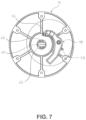
- the floor base 12 may further include a slot 60 positioned in the bottom surface 32 .
- the slot 60 may be sized and shaped to fit the head 42 of the T-bolt 40 therethrough, such as generally rectangular.
- FIG. 7 from an underside view of the floor base 12 , include a hard stop 62 positioned adjacent to the slot 60 on the underside of the floor base 12 .
- the hard stop 62 may abut the head 42 of the T-bolt 40 once it is inserted into the slot 60 and rotated.
- the hard stop 62 is positioned to allow 90 degrees of rotation of the T-bolt head 42 to position the head 42 perpendicular to the slot 62 . This positioning prevents the T-bolt 40 from being removed from engagement with the base 12 while abutted with the hard stop 62 .
- the pedestal leg assembly 10 may be provided with the T-bolt 40 at least partially inserted into the floor base 12 aligning the T-bolt head 42 with the slot 62 and inserting it therethrough.
- the leg assembly 10 may then be rotated in a first direction, such as clockwise.
- the T-bolt head 42 will abut the hard stop 62 when the head is rotated approximately 90 degrees from the slot position.
- the pedestal leg assembly 10 may continue to be rotated in a clockwise direction once the T-bolt head 42 abuts the hard stop 62 , which will serve to screw the T-bolt 40 into the threaded opening 38 thereby tightening the T-bolt's connection to the floor base 12 , until the connection is fully tightened.
- the release lever 48 may be in lock position, which is the default position due to the biasing spring 56 .
- the angle of the teeth 46 combined with the angle of the notch 52 may allow rotation of the pedestal leg assembly 10 in a clockwise direction to tighten the leg assembly 10 but may prevent any counterclockwise rotation of the leg assembly 10 to loosen the connection or allow rotation of the T-bolt head 42 back into alignment with the slot 62 to facilitate removal of the leg 10 .
- the release lever 48 may be moved into release position by pressing the tab 58 to override the force of the biasing spring 56 and pivot the notch 52 away from the hole 54 .
- leg assembly 10 may be freely rotated in either direction, and may be unscrewed in counterclockwise direction to loosen the connection with the floor base and rotate the T-bolt head into alignment with the slot 62 to remove the leg assembly 10 from the floor base.
- the leg assembly 10 may be configured to allow both connection and disconnection of the leg 18 when the release lever 48 is depressed.
- the bottom end 22 of the leg 18 may include teeth 130 that are oriented vertically to engage one or more similar fixed teeth 132 on the release lever 48 .
- the vertical orientation of the teeth 130 , 132 may prevent any movement or rotation of the leg 18 in either direction while the teeth 130 , 132 are integrated.
- a spring 134 such as a leaf spring, may be positioned under the release mechanism 48 to bias the release mechanism upwards and away from a supporting surface.
- the release mechanism 48 may pivot downward, toward the supporting surface, and away from the hole 54 and any potential engagement with an inserted leg 18 .
- the T-bolt head 42 may be inserted through the slot 62 .
- the tab or button 58 may be depressed to lower the release lever 48 out of lock position and into release position, away from hole 54 in the sidewall 30 and out of position where it would engage the teeth 130 on the leg 18 .
- the T-bolt 40 may engage the hard stop 62 and the leg 18 may be rotated, while the release lever 48 is depressed, until the T-bolt 40 is fully and tightly connected to the base 12 .
- the release lever 48 may then be released and the teeth 130 , 132 may engage.
- the engaged teeth 130 , 132 act as a rotation lock to prevent any unwanted rotation of the leg 18 , to prevent both unscrewing of the leg 18 or over locking of the leg 18 .
- the release lever 48 may be depressed and leg 18 may be unscrewed and the T-bolt head 42 aligned with the slot 62 to remove the leg 18 .
- the pedestal leg assembly 10 may include a powered connection.
- the powered connection may be received through the floor base 12 and transfer power through the leg 18 and to a table top 14 .
- the power connection may include a power signal, a communication signal, or a combination thereof.
- the components of the powered leg assembly 10 described below may be used alone or in conjunction with the locking components pedestal leg assembly 10 described above.
- the floor base 12 may include an electrical power connection.
- the floor base 12 may be configured to safely connect power to and through the leg 18 , as described below.
- the power connection may be an AC power connection, such as a 120 VAC connection, or a DC power connection, such as a 12 VDC power connection.
- the pedestal leg assembly 10 is shown and described as having a two wired connection, it will be appreciated that the same or similar designs to those described herein may be implemented using a three-wire, four-wire, or any number of wires in a wired connection.
- the floor base 12 may be configured to mechanically and electrically receive a powered connection.
- the floor base 12 may include a plug opening 72 in the bottom surface 32 .
- the plug opening 72 may be sized and shaped to receive one or more electrical connections, such as connection wires, or a supporting fixture or assembly therethrough.
- a contact assembly 74 may connect to the floor base 12 and provide a housing for the electrical connection.
- the contact assembly 74 may comprise a top holder 76 and bottom holder 78 configured to house the electrical connection parts and interconnect the input power with the floor base 12 .
- the top and bottom holders 76 , 78 may be circular and generally flat and configured to engage one another to contain electrical connection components therebetween.
- the top holder 76 may include a plug 80 sized and shaped to insert and protrude through the plug opening 72 .
- the bottom holder 78 may include one or more, such as a pair, of pogo pin receptacles 82 .
- the receptacles 82 may be configured to hold pogo pins 84 in a fixed position.
- the pogo pins 84 may each be surrounded by a spring 86 and covered by a retainer 88 .
- the retainers 88 may be biased away from the pins 84 and may be pushed toward the pins when a force is applied thereon.
- the retainers 88 may be formed of a non-conductive material, such as plastic, and may generally comprise a cylindrical outer guard to protect the pins 84 from unwanted contact.
- the retainers may include openings at the top of each cylindrical guard to allow contact with the pins therethrough.
- a wire harness 90 may connect to the bottom holder 78 to provide an input electrical connection 92 .
- the wire harness 90 may comprise any bundle of electrically powered wires.
- the wires may connect to an underside of the bottom holder 78 to conduct power to the pins 84 .
- the floor base 12 may include a mechanically activated safety switch.
- the switch may be configured to relay power from the harness 90 to the pogo pins 84 .
- the switch may be activated by sensing that a pedestal leg assembly 10 is inserted into the floor base 12 .
- the switch may be activated by receiving a mechanical input, such as a protrusion from the leg assembly 10 when inserted into the floor base opening 28 , to activate the switch and relay power from the harness 90 to the pins 84 .
- other sensing mechanisms such as magnetic or other sensing devices, may be used to sense when contact is made between the leg assembly 10 and the floor base 12 .
- the retainers 88 When the top and bottom holders 76 , 78 are assembled, the retainers 88 may protrude from the openings of the plug 80 , as shown in FIG. 9 .
- the retainers 88 may depress when a force is applied thereon to push down and expose the pogo pins 84 . The exposed pins may then conduct power to any contacted device.
- the leg assembly 10 may be configured to receive power at its bottom end and transfer the power through the leg 18 .
- the end cap 34 may comprise a ring contact 94 and ring contact holder 96 .
- the ring contact 94 and contact holder 96 may both be generally circular and having a central opening to allow the T-bolt 40 to protrude therethrough.
- the contact holder 96 may hold the contact ring 94 in place and provide an insulating outside surface to prevent unwanted electrical contact with the ring 94 .
- the contact ring 94 may include one or more contact surfaces 98 isolated from one another.
- the contact ring 94 may include two contact surfaces 98 arranged concentrically from one another. The contact surfaces may be isolated to allow one surface to carry a first power signal, such as high voltage, and the second surface to carry a common or ground signal.
- the contact ring 94 may be arranged to face the contact surfaces toward the floor base 12 .
- the retainers 88 and pogo pins 84 may be positioned so as to align when the leg assembly 10 and floor base 12 are engaged.
- a first contact surface 98 may align with a first pogo pin 84 and a second contact surface 98 may align with a second pogo pin 84 to individually transfer power signals from each pin 84 to a contact surface 98 on the contact ring 94 .
- the contact ring 94 may depress the retainers 88 , exposing the pogo pins 84 and creating an electrical contact between the pins 84 and the respective contact surfaces 98 .
- the leg assembly 10 may include insulated power busses or wires 95 to transfer power connections from the bottom end 22 to the top end 22 of the assembly 10 .
- the transfer bus 95 may comprise isolated wire or wires, conductive paths integrated into the interior of the leg 18 , or any other means of transferring the input power to the top end 20 of the assembly 10 .
- the top end 20 may be configured to pass power from the power bus 95 to the top surface 14 .
- a contact holder 100 may be inserted into the top end 20 and positioned near an opening in the top end 20 .
- the contact holder may receive a power connection from a transfer harness 102 .
- the transfer harness 102 may specifically interconnect the bus 95 with the contact holder 100 .
- the contact holder 100 may include openings 104 to receive contact pins, such as pogo pins 106 therethrough.
- the pogo pins 106 may connect to the transfer harness 102 and extend power through the contact holder 100 .
- a spring or biasing member 108 may be placed over each pogo pin 106 an covered by a pogo sleeve 110 .
- the sleeve 110 may include an opening that allows the pogo pin 106 to protrude therethrough only when a force is applied to the sleeve 110 to depress the spring 108 .
- a retainer 112 may be placed over the sleeves 110 to protect them from unwanted contact and retain them in place.
- the top end 20 of the leg assembly 10 may be configured to interface with a power distribution assembly 114 of a top surface 14 .
- the top surface 14 may include one or more powered applications, such as lights, outlets, and the like. Each powered application may be fed by power distribution connector 116 .
- the connectors 108 may be wired back to a central power hub 118 , such as a printed circuit board (“PCB”).
- the power hub or PCB 118 may be configured to receive a plurality of power distribution connectors 108 and feed them from a single input power line.
- the top surface 14 may include a PCB holder 120 to support the PCB 118 .
- the PCB holder 112 may connect to the underside of the top surface 14 and hold the PCB 118 therein.
- a potting 119 may be filled above the PCB 118 to protect the PCB from water or other environmental hazards.
- the PCB holder 120 may be generally sized and shaped to extend into the opening in the top end 20 of the leg 18 .
- the PCB holder 120 may be generally cylindrical and configured to extend down into the top opening of the leg 18 when the top surface 14 is rested on the table base 24 .
- the PCB holder 120 may include a top ring contact 122 connected thereto.
- the top ring contact 112 may include one or more contact surfaces isolated from one another and aligned to engage the pogo pins 106 when the PCB holder 120 is inserted into the top of the leg 18 .
- the leg assembly 10 may be connected to a base 12 by inserting the T-bolt 40 into the slot 60 and rotating the leg assembly 10 .
- the release lever 48 may allow rotation in a first direction and prevent rotation in the opposite direction, to allow the leg assembly 10 to be screwed into place.
- the T-bolt head 42 may abut the hard stop 62 and rotation of the leg assembly 10 may tighten the T-bolt 40 to the base 12 .
- the ring contact 94 may engage and depress the retainers 88 to contact the lower pogo pins 84 and create a connection between the input power 92 and the transfer bus 95 .
- the transfer bus may provide an electrical connection to the transfer harness 102 which may feed power to the upper pogo pins 106 which are housed in the contact holder 110 .
- a top surface 14 having a PCB holder 120 and contact ring 112 may be inserted into the top end 20 of the leg 18 .
- the contact ring 112 may engage the retainer 112 and depress the sleeve 110 and spring 108 to contact the pogo pins 106 and provide a powered connection to the table top 14 .
- the release tab 58 may be activated to remove the release lever 48 away from the teeth 46 and allow the T-bolt 40 to be unscrewed and removed from the base 12 .
Landscapes
- Engineering & Computer Science (AREA)
- Mechanical Engineering (AREA)
- General Engineering & Computer Science (AREA)
- Transportation (AREA)
- Legs For Furniture In General (AREA)
Abstract
Description
Claims (17)
Priority Applications (1)
| Application Number | Priority Date | Filing Date | Title |
|---|---|---|---|
| US17/705,573 US12108872B2 (en) | 2019-09-06 | 2022-03-28 | Pedestal leg assembly |
Applications Claiming Priority (3)
| Application Number | Priority Date | Filing Date | Title |
|---|---|---|---|
| US16/563,268 US10918203B1 (en) | 2019-09-06 | 2019-09-06 | Pedestal leg assembly |
| US17/136,810 US11304509B2 (en) | 2019-09-06 | 2020-12-29 | Pedestal leg assembly |
| US17/705,573 US12108872B2 (en) | 2019-09-06 | 2022-03-28 | Pedestal leg assembly |
Related Parent Applications (1)
| Application Number | Title | Priority Date | Filing Date |
|---|---|---|---|
| US17/136,810 Continuation-In-Part US11304509B2 (en) | 2019-09-06 | 2020-12-29 | Pedestal leg assembly |
Publications (2)
| Publication Number | Publication Date |
|---|---|
| US20220211171A1 US20220211171A1 (en) | 2022-07-07 |
| US12108872B2 true US12108872B2 (en) | 2024-10-08 |
Family
ID=82219901
Family Applications (1)
| Application Number | Title | Priority Date | Filing Date |
|---|---|---|---|
| US17/705,573 Active 2040-04-28 US12108872B2 (en) | 2019-09-06 | 2022-03-28 | Pedestal leg assembly |
Country Status (1)
| Country | Link |
|---|---|
| US (1) | US12108872B2 (en) |
Cited By (2)
| Publication number | Priority date | Publication date | Assignee | Title |
|---|---|---|---|---|
| US20240060325A1 (en) * | 2022-08-22 | 2024-02-22 | Aftercloud Technology Co., Ltd | Center pole fixing structure |
| US20240122350A1 (en) * | 2022-10-15 | 2024-04-18 | Society Brands, Inc. | Active Seating Apparatus and Method of Assembly and Use |
Citations (50)
| Publication number | Priority date | Publication date | Assignee | Title |
|---|---|---|---|---|
| US1193252A (en) | 1916-08-01 | freeman | ||
| US2037232A (en) | 1935-04-22 | 1936-04-14 | Arthur H Boettcher | Trolley anchor |
| US2967585A (en) | 1957-12-06 | 1961-01-10 | Charles L Bybee | Adjustable scaffold support |
| US3540386A (en) | 1968-02-21 | 1970-11-17 | Sven Ivar Natanael Hall | Collapsible table |
| US4807838A (en) | 1988-01-20 | 1989-02-28 | Shaw-Walker Company | Table leg with wire raceway |
| US5026010A (en) | 1990-05-04 | 1991-06-25 | Itc Incorporated | Latched detachable leg assembly |
| US5037232A (en) | 1990-05-04 | 1991-08-06 | Prasit Pakdipanichpong | Table leg lock |
| US5121891A (en) | 1991-04-11 | 1992-06-16 | Todd Enterprises, Inc. | Transferable stanchion system |
| US5383644A (en) | 1993-04-14 | 1995-01-24 | Moeller Marine Products | Removable pedestal |
| US5485793A (en) | 1993-02-08 | 1996-01-23 | Crowell; Anthony D. | Vehicle desk |
| EP0707806A2 (en) | 1994-10-19 | 1996-04-24 | Herman Miller, Inc. | Adjustable work surface |
| US5826850A (en) | 1997-02-12 | 1998-10-27 | Chem-Tainer Industries, Inc. | Rotatable and transferable stanchion assembly having a releasable lock |
| EP1192874A1 (en) | 2000-09-29 | 2002-04-03 | Sedus Stoll AG | Table |
| US6588717B2 (en) | 1999-12-06 | 2003-07-08 | Garnett Carnahan | Planar assembly support |
| US20030160139A1 (en) | 2002-02-22 | 2003-08-28 | Camarota Richard J. | Table leg attachment system |
| US20050178300A1 (en) | 2004-02-17 | 2005-08-18 | Gar Products, Inc. | Table base |
| US20060130714A1 (en) | 2004-12-17 | 2006-06-22 | Steelcase Development Corporation | Load compensator for height adjustable table |
| US20070125929A1 (en) | 2005-12-05 | 2007-06-07 | L&P Property Management Company | Interlocking, interchangeable support base system |
| CA2568078A1 (en) | 2006-11-14 | 2008-05-14 | Unifor S.P.A. | Telescopic table support |
| US20080111046A1 (en) * | 2006-11-14 | 2008-05-15 | Benson Tung | Sunshade base with swivel seat |
| US20080223261A1 (en) | 2007-03-15 | 2008-09-18 | John Frederick | Table assembly |
| US20090183653A1 (en) | 2004-08-02 | 2009-07-23 | Rory Brooke | Tables |
| US7626120B1 (en) | 2007-05-01 | 2009-12-01 | Premier Manufacturing Group, Inc. | Pop-up power and communication outlet apparatus for use with a table, desk or similar article |
| US20100290215A1 (en) | 2009-05-12 | 2010-11-18 | Kimball International, Inc. | Furniture with wireless power |
| US20110097928A1 (en) * | 2009-10-22 | 2011-04-28 | Donald Andrew Burris | Locking Ratcheting Torque Aid |
| US20130327569A1 (en) | 2012-06-07 | 2013-12-12 | Doug Mockett & Company, Inc. | Power and communications grommet |
| US20140096706A1 (en) | 2012-10-10 | 2014-04-10 | Jean-Paul Labrosse | Height-Adjustable Support Surface and System for Encouraging Human Movement and Promoting Wellness |
| US8807513B2 (en) * | 2012-05-21 | 2014-08-19 | Dee Volin | Unique multi-adjustable rotating-and-locking umbrella-stanchion system |
| US20140338573A1 (en) | 2013-05-16 | 2014-11-20 | Attiture Llc | Furniture Line and Method and System for Providing Customization Thereof |
| CN104364537A (en) | 2012-06-13 | 2015-02-18 | 共进产业株式会社 | pillar structure |
| CN104366969A (en) | 2014-10-30 | 2015-02-25 | 无锡艾科瑞思产品设计与研究有限公司 | Table |
| US20150096473A1 (en) | 2013-10-07 | 2015-04-09 | C + P Mobelsysteme GmbH & Co. KG | Table device |
| US20150236456A1 (en) | 2014-02-18 | 2015-08-20 | Pedro Arroyo Sosa | Easy Plug |
| US9368924B2 (en) | 2014-05-09 | 2016-06-14 | Norman R. Byrne | Electrical receptacle assembly with housing |
| KR101634523B1 (en) | 2015-02-13 | 2016-06-29 | 강세원 | Prefabricated table, and multipurpose table package of using the same |
| US20160278527A1 (en) * | 2013-09-16 | 2016-09-29 | Matthew J. Planer | Stationary Restraint System for Police Structures |
| US20170020279A1 (en) | 2015-07-21 | 2017-01-26 | Mustafa A. Ergun | Gas spring lift |
| US20170063148A1 (en) | 2015-09-01 | 2017-03-02 | Yuan Min Wang | Outdoor multifunctional solar energy foldable table |
| US20170318958A1 (en) | 2016-05-09 | 2017-11-09 | James Nathaniel Asante | Multi-function travel-friendly workstation with cooling and ventilation |
| US20170357146A1 (en) | 2016-06-10 | 2017-12-14 | Spark S.R.L. | Support and connection unit for cameras |
| US20180000241A1 (en) | 2016-06-29 | 2018-01-04 | Zhejiang Yotrio Group Co., Ltd. | Combined table-umbrella |
| US9957728B2 (en) * | 2013-09-19 | 2018-05-01 | Oliver Joen-An Ma | Rotation base for umbrella |
| DE102016015594A1 (en) | 2016-12-29 | 2018-07-05 | Kusch + Co. Gmbh & Co. Kg | seating |
| US10051960B1 (en) | 2015-12-02 | 2018-08-21 | Brunswick Corporation | Combination chair and desk apparatus |
| US20180313383A1 (en) | 2017-04-27 | 2018-11-01 | Mogogo Ltd | Quick Lock-Release Mechanism for Assembling a Table Plate to Table Legs |
| US20190086067A1 (en) | 2016-05-20 | 2019-03-21 | Opple Lighting Co., Ltd. | Adapter, light source device and illuminating device |
| US20200052474A1 (en) | 2016-12-20 | 2020-02-13 | Point Pod Pty. Ltd. | Improvements to power outlets for benches |
| US20200050239A1 (en) | 2018-08-08 | 2020-02-13 | Hewlett-Packard Development Company, L.P. | Adjustment control mechanisms of pogo pins |
| US20200085185A1 (en) | 2017-03-21 | 2020-03-19 | Rol Ergo Ab | Telescopic column with internal cable |
| US20200227942A1 (en) | 2019-01-16 | 2020-07-16 | Chemtronics Co., Ltd. | Wireless charger and furniture having the same |
-
2022
- 2022-03-28 US US17/705,573 patent/US12108872B2/en active Active
Patent Citations (53)
| Publication number | Priority date | Publication date | Assignee | Title |
|---|---|---|---|---|
| US1193252A (en) | 1916-08-01 | freeman | ||
| US2037232A (en) | 1935-04-22 | 1936-04-14 | Arthur H Boettcher | Trolley anchor |
| US2967585A (en) | 1957-12-06 | 1961-01-10 | Charles L Bybee | Adjustable scaffold support |
| US3540386A (en) | 1968-02-21 | 1970-11-17 | Sven Ivar Natanael Hall | Collapsible table |
| US4807838A (en) | 1988-01-20 | 1989-02-28 | Shaw-Walker Company | Table leg with wire raceway |
| US5026010A (en) | 1990-05-04 | 1991-06-25 | Itc Incorporated | Latched detachable leg assembly |
| US5037232A (en) | 1990-05-04 | 1991-08-06 | Prasit Pakdipanichpong | Table leg lock |
| US5121891A (en) | 1991-04-11 | 1992-06-16 | Todd Enterprises, Inc. | Transferable stanchion system |
| US5485793A (en) | 1993-02-08 | 1996-01-23 | Crowell; Anthony D. | Vehicle desk |
| US5383644A (en) | 1993-04-14 | 1995-01-24 | Moeller Marine Products | Removable pedestal |
| EP0707806A2 (en) | 1994-10-19 | 1996-04-24 | Herman Miller, Inc. | Adjustable work surface |
| US5826850A (en) | 1997-02-12 | 1998-10-27 | Chem-Tainer Industries, Inc. | Rotatable and transferable stanchion assembly having a releasable lock |
| US6588717B2 (en) | 1999-12-06 | 2003-07-08 | Garnett Carnahan | Planar assembly support |
| EP1192874A1 (en) | 2000-09-29 | 2002-04-03 | Sedus Stoll AG | Table |
| US20030160139A1 (en) | 2002-02-22 | 2003-08-28 | Camarota Richard J. | Table leg attachment system |
| US6820847B2 (en) | 2002-02-22 | 2004-11-23 | Itc Incorporated | Table leg attachment system |
| US20050178300A1 (en) | 2004-02-17 | 2005-08-18 | Gar Products, Inc. | Table base |
| AU2004322231B2 (en) | 2004-08-02 | 2011-03-10 | Hedera Ab | Tables |
| US20090183653A1 (en) | 2004-08-02 | 2009-07-23 | Rory Brooke | Tables |
| US20060130714A1 (en) | 2004-12-17 | 2006-06-22 | Steelcase Development Corporation | Load compensator for height adjustable table |
| US7886674B2 (en) | 2005-12-05 | 2011-02-15 | L&P Property Management Company | Interlocking, interchangeable support base system |
| US20070125929A1 (en) | 2005-12-05 | 2007-06-07 | L&P Property Management Company | Interlocking, interchangeable support base system |
| US20080111046A1 (en) * | 2006-11-14 | 2008-05-15 | Benson Tung | Sunshade base with swivel seat |
| CA2568078A1 (en) | 2006-11-14 | 2008-05-14 | Unifor S.P.A. | Telescopic table support |
| US20080223261A1 (en) | 2007-03-15 | 2008-09-18 | John Frederick | Table assembly |
| US7626120B1 (en) | 2007-05-01 | 2009-12-01 | Premier Manufacturing Group, Inc. | Pop-up power and communication outlet apparatus for use with a table, desk or similar article |
| US20100290215A1 (en) | 2009-05-12 | 2010-11-18 | Kimball International, Inc. | Furniture with wireless power |
| US20110097928A1 (en) * | 2009-10-22 | 2011-04-28 | Donald Andrew Burris | Locking Ratcheting Torque Aid |
| US8807513B2 (en) * | 2012-05-21 | 2014-08-19 | Dee Volin | Unique multi-adjustable rotating-and-locking umbrella-stanchion system |
| US20130327569A1 (en) | 2012-06-07 | 2013-12-12 | Doug Mockett & Company, Inc. | Power and communications grommet |
| CN104364537A (en) | 2012-06-13 | 2015-02-18 | 共进产业株式会社 | pillar structure |
| US20140096706A1 (en) | 2012-10-10 | 2014-04-10 | Jean-Paul Labrosse | Height-Adjustable Support Surface and System for Encouraging Human Movement and Promoting Wellness |
| US20140338573A1 (en) | 2013-05-16 | 2014-11-20 | Attiture Llc | Furniture Line and Method and System for Providing Customization Thereof |
| US20160278527A1 (en) * | 2013-09-16 | 2016-09-29 | Matthew J. Planer | Stationary Restraint System for Police Structures |
| US9957728B2 (en) * | 2013-09-19 | 2018-05-01 | Oliver Joen-An Ma | Rotation base for umbrella |
| US20150096473A1 (en) | 2013-10-07 | 2015-04-09 | C + P Mobelsysteme GmbH & Co. KG | Table device |
| US20150236456A1 (en) | 2014-02-18 | 2015-08-20 | Pedro Arroyo Sosa | Easy Plug |
| US9368924B2 (en) | 2014-05-09 | 2016-06-14 | Norman R. Byrne | Electrical receptacle assembly with housing |
| CN104366969A (en) | 2014-10-30 | 2015-02-25 | 无锡艾科瑞思产品设计与研究有限公司 | Table |
| KR101634523B1 (en) | 2015-02-13 | 2016-06-29 | 강세원 | Prefabricated table, and multipurpose table package of using the same |
| US20170020279A1 (en) | 2015-07-21 | 2017-01-26 | Mustafa A. Ergun | Gas spring lift |
| US20170063148A1 (en) | 2015-09-01 | 2017-03-02 | Yuan Min Wang | Outdoor multifunctional solar energy foldable table |
| US10051960B1 (en) | 2015-12-02 | 2018-08-21 | Brunswick Corporation | Combination chair and desk apparatus |
| US20170318958A1 (en) | 2016-05-09 | 2017-11-09 | James Nathaniel Asante | Multi-function travel-friendly workstation with cooling and ventilation |
| US20190086067A1 (en) | 2016-05-20 | 2019-03-21 | Opple Lighting Co., Ltd. | Adapter, light source device and illuminating device |
| US20170357146A1 (en) | 2016-06-10 | 2017-12-14 | Spark S.R.L. | Support and connection unit for cameras |
| US20180000241A1 (en) | 2016-06-29 | 2018-01-04 | Zhejiang Yotrio Group Co., Ltd. | Combined table-umbrella |
| US20200052474A1 (en) | 2016-12-20 | 2020-02-13 | Point Pod Pty. Ltd. | Improvements to power outlets for benches |
| DE102016015594A1 (en) | 2016-12-29 | 2018-07-05 | Kusch + Co. Gmbh & Co. Kg | seating |
| US20200085185A1 (en) | 2017-03-21 | 2020-03-19 | Rol Ergo Ab | Telescopic column with internal cable |
| US20180313383A1 (en) | 2017-04-27 | 2018-11-01 | Mogogo Ltd | Quick Lock-Release Mechanism for Assembling a Table Plate to Table Legs |
| US20200050239A1 (en) | 2018-08-08 | 2020-02-13 | Hewlett-Packard Development Company, L.P. | Adjustment control mechanisms of pogo pins |
| US20200227942A1 (en) | 2019-01-16 | 2020-07-16 | Chemtronics Co., Ltd. | Wireless charger and furniture having the same |
Cited By (3)
| Publication number | Priority date | Publication date | Assignee | Title |
|---|---|---|---|---|
| US20240060325A1 (en) * | 2022-08-22 | 2024-02-22 | Aftercloud Technology Co., Ltd | Center pole fixing structure |
| US12398575B2 (en) * | 2022-08-22 | 2025-08-26 | Aftercloud Technology Co., Ltd | Center pole fixing structure |
| US20240122350A1 (en) * | 2022-10-15 | 2024-04-18 | Society Brands, Inc. | Active Seating Apparatus and Method of Assembly and Use |
Also Published As
| Publication number | Publication date |
|---|---|
| US20220211171A1 (en) | 2022-07-07 |
Similar Documents
| Publication | Publication Date | Title |
|---|---|---|
| US10918203B1 (en) | Pedestal leg assembly | |
| US11304509B2 (en) | Pedestal leg assembly | |
| JP4508658B2 (en) | Electrical adapter | |
| US12108872B2 (en) | Pedestal leg assembly | |
| US5989070A (en) | Bulb socket adapter | |
| US11424577B2 (en) | High-current electrical connector and electrical connector system | |
| US5460542A (en) | Multiple-outlet receptacle | |
| US6322376B1 (en) | Stud bolt holder for a power distribution box | |
| US7438566B2 (en) | Electric distributing system | |
| US9276353B2 (en) | Protective lockable female electrical outlet | |
| US5660554A (en) | Universal plug adaptor | |
| US4740178A (en) | Battery terminal connection apparatus | |
| US8500477B2 (en) | Individual loading mechanism with simplified locking arrangement | |
| CN104919660A (en) | Cable Connector System | |
| KR20190127129A (en) | Connecting device for connecting socket and plug | |
| US11804678B2 (en) | Power supply adapter | |
| US6234850B1 (en) | Electrical terminal arrangement | |
| GB2126805A (en) | Electrical plug | |
| JP2003197026A (en) | Wiring equipment, wiring equipment and lighting duct equipment | |
| US20010018277A1 (en) | Safety electrical outlet | |
| CN110622359B (en) | Connecting device for connecting at least one electrical conductor to a screw terminal | |
| US1837058A (en) | Separable electric fitting | |
| GB2098411A (en) | Electrical plugs | |
| CN115513725B (en) | Power conversion device | |
| US11726110B2 (en) | Connecting device for connecting an electrical device under test to a test instrument |
Legal Events
| Date | Code | Title | Description |
|---|---|---|---|
| FEPP | Fee payment procedure |
Free format text: ENTITY STATUS SET TO UNDISCOUNTED (ORIGINAL EVENT CODE: BIG.); ENTITY STATUS OF PATENT OWNER: SMALL ENTITY |
|
| AS | Assignment |
Owner name: ITC INCORPORATED, MICHIGAN Free format text: ASSIGNMENT OF ASSIGNORS INTEREST;ASSIGNORS:SCHNEIDER, THEODORE;RATHBUN, JON;XU, QINGQI;SIGNING DATES FROM 20200204 TO 20200210;REEL/FRAME:059439/0036 |
|
| FEPP | Fee payment procedure |
Free format text: ENTITY STATUS SET TO SMALL (ORIGINAL EVENT CODE: SMAL); ENTITY STATUS OF PATENT OWNER: SMALL ENTITY |
|
| STPP | Information on status: patent application and granting procedure in general |
Free format text: DOCKETED NEW CASE - READY FOR EXAMINATION |
|
| STPP | Information on status: patent application and granting procedure in general |
Free format text: NON FINAL ACTION MAILED |
|
| STPP | Information on status: patent application and granting procedure in general |
Free format text: RESPONSE TO NON-FINAL OFFICE ACTION ENTERED AND FORWARDED TO EXAMINER |
|
| STPP | Information on status: patent application and granting procedure in general |
Free format text: NOTICE OF ALLOWANCE MAILED -- APPLICATION RECEIVED IN OFFICE OF PUBLICATIONS |
|
| STPP | Information on status: patent application and granting procedure in general |
Free format text: PUBLICATIONS -- ISSUE FEE PAYMENT RECEIVED |
|
| STPP | Information on status: patent application and granting procedure in general |
Free format text: PUBLICATIONS -- ISSUE FEE PAYMENT VERIFIED |
|
| STCF | Information on status: patent grant |
Free format text: PATENTED CASE |
|
| AS | Assignment |
Owner name: COMERICA BANK, MICHIGAN Free format text: SECURITY INTEREST;ASSIGNOR:ITC INCORPORATED;REEL/FRAME:069505/0118 Effective date: 20241118 |