US12102985B2 - Metal particle-loaded hollow mesoporous organosilica nano/microparticles and method for manufacturing same - Google Patents
Metal particle-loaded hollow mesoporous organosilica nano/microparticles and method for manufacturing same Download PDFInfo
- Publication number
- US12102985B2 US12102985B2 US17/312,246 US202017312246A US12102985B2 US 12102985 B2 US12102985 B2 US 12102985B2 US 202017312246 A US202017312246 A US 202017312246A US 12102985 B2 US12102985 B2 US 12102985B2
- Authority
- US
- United States
- Prior art keywords
- metal particles
- metal
- inorganic silica
- inorganic
- silica
- Prior art date
- Legal status (The legal status is an assumption and is not a legal conclusion. Google has not performed a legal analysis and makes no representation as to the accuracy of the status listed.)
- Active, expires
Links
Images


Classifications
-
- B—PERFORMING OPERATIONS; TRANSPORTING
- B01—PHYSICAL OR CHEMICAL PROCESSES OR APPARATUS IN GENERAL
- B01J—CHEMICAL OR PHYSICAL PROCESSES, e.g. CATALYSIS OR COLLOID CHEMISTRY; THEIR RELEVANT APPARATUS
- B01J23/00—Catalysts comprising metals or metal oxides or hydroxides, not provided for in group B01J21/00
- B01J23/38—Catalysts comprising metals or metal oxides or hydroxides, not provided for in group B01J21/00 of noble metals
- B01J23/48—Silver or gold
- B01J23/52—Gold
-
- A—HUMAN NECESSITIES
- A61—MEDICAL OR VETERINARY SCIENCE; HYGIENE
- A61K—PREPARATIONS FOR MEDICAL, DENTAL OR TOILETRY PURPOSES
- A61K41/00—Medicinal preparations obtained by treating materials with wave energy or particle radiation ; Therapies using these preparations
- A61K41/0052—Thermotherapy; Hyperthermia; Magnetic induction; Induction heating therapy
-
- A—HUMAN NECESSITIES
- A61—MEDICAL OR VETERINARY SCIENCE; HYGIENE
- A61K—PREPARATIONS FOR MEDICAL, DENTAL OR TOILETRY PURPOSES
- A61K9/00—Medicinal preparations characterised by special physical form
- A61K9/0002—Galenical forms characterised by the drug release technique; Application systems commanded by energy
- A61K9/0004—Osmotic delivery systems; Sustained release driven by osmosis, thermal energy or gas
-
- A—HUMAN NECESSITIES
- A61—MEDICAL OR VETERINARY SCIENCE; HYGIENE
- A61K—PREPARATIONS FOR MEDICAL, DENTAL OR TOILETRY PURPOSES
- A61K9/00—Medicinal preparations characterised by special physical form
- A61K9/48—Preparations in capsules, e.g. of gelatin, of chocolate
- A61K9/50—Microcapsules having a gas, liquid or semi-solid filling; Solid microparticles or pellets surrounded by a distinct coating layer, e.g. coated microspheres, coated drug crystals
- A61K9/51—Nanocapsules; Nanoparticles
- A61K9/5107—Excipients; Inactive ingredients
- A61K9/5115—Inorganic compounds
-
- A—HUMAN NECESSITIES
- A61—MEDICAL OR VETERINARY SCIENCE; HYGIENE
- A61K—PREPARATIONS FOR MEDICAL, DENTAL OR TOILETRY PURPOSES
- A61K9/00—Medicinal preparations characterised by special physical form
- A61K9/48—Preparations in capsules, e.g. of gelatin, of chocolate
- A61K9/50—Microcapsules having a gas, liquid or semi-solid filling; Solid microparticles or pellets surrounded by a distinct coating layer, e.g. coated microspheres, coated drug crystals
- A61K9/51—Nanocapsules; Nanoparticles
- A61K9/5192—Processes
-
- B—PERFORMING OPERATIONS; TRANSPORTING
- B01—PHYSICAL OR CHEMICAL PROCESSES OR APPARATUS IN GENERAL
- B01J—CHEMICAL OR PHYSICAL PROCESSES, e.g. CATALYSIS OR COLLOID CHEMISTRY; THEIR RELEVANT APPARATUS
- B01J13/00—Colloid chemistry, e.g. the production of colloidal materials or their solutions, not otherwise provided for; Making microcapsules or microballoons
- B01J13/02—Making microcapsules or microballoons
- B01J13/06—Making microcapsules or microballoons by phase separation
- B01J13/14—Polymerisation; cross-linking
- B01J13/18—In situ polymerisation with all reactants being present in the same phase
-
- B—PERFORMING OPERATIONS; TRANSPORTING
- B01—PHYSICAL OR CHEMICAL PROCESSES OR APPARATUS IN GENERAL
- B01J—CHEMICAL OR PHYSICAL PROCESSES, e.g. CATALYSIS OR COLLOID CHEMISTRY; THEIR RELEVANT APPARATUS
- B01J13/00—Colloid chemistry, e.g. the production of colloidal materials or their solutions, not otherwise provided for; Making microcapsules or microballoons
- B01J13/02—Making microcapsules or microballoons
- B01J13/20—After-treatment of capsule walls, e.g. hardening
- B01J13/203—Exchange of core-forming material by diffusion through the capsule wall
-
- B—PERFORMING OPERATIONS; TRANSPORTING
- B01—PHYSICAL OR CHEMICAL PROCESSES OR APPARATUS IN GENERAL
- B01J—CHEMICAL OR PHYSICAL PROCESSES, e.g. CATALYSIS OR COLLOID CHEMISTRY; THEIR RELEVANT APPARATUS
- B01J13/00—Colloid chemistry, e.g. the production of colloidal materials or their solutions, not otherwise provided for; Making microcapsules or microballoons
- B01J13/02—Making microcapsules or microballoons
- B01J13/20—After-treatment of capsule walls, e.g. hardening
- B01J13/22—Coating
-
- B—PERFORMING OPERATIONS; TRANSPORTING
- B01—PHYSICAL OR CHEMICAL PROCESSES OR APPARATUS IN GENERAL
- B01J—CHEMICAL OR PHYSICAL PROCESSES, e.g. CATALYSIS OR COLLOID CHEMISTRY; THEIR RELEVANT APPARATUS
- B01J21/00—Catalysts comprising the elements, oxides, or hydroxides of magnesium, boron, aluminium, carbon, silicon, titanium, zirconium, or hafnium
- B01J21/06—Silicon, titanium, zirconium or hafnium; Oxides or hydroxides thereof
- B01J21/08—Silica
-
- B—PERFORMING OPERATIONS; TRANSPORTING
- B01—PHYSICAL OR CHEMICAL PROCESSES OR APPARATUS IN GENERAL
- B01J—CHEMICAL OR PHYSICAL PROCESSES, e.g. CATALYSIS OR COLLOID CHEMISTRY; THEIR RELEVANT APPARATUS
- B01J23/00—Catalysts comprising metals or metal oxides or hydroxides, not provided for in group B01J21/00
- B01J23/38—Catalysts comprising metals or metal oxides or hydroxides, not provided for in group B01J21/00 of noble metals
- B01J23/40—Catalysts comprising metals or metal oxides or hydroxides, not provided for in group B01J21/00 of noble metals of the platinum group metals
- B01J23/44—Palladium
-
- B—PERFORMING OPERATIONS; TRANSPORTING
- B01—PHYSICAL OR CHEMICAL PROCESSES OR APPARATUS IN GENERAL
- B01J—CHEMICAL OR PHYSICAL PROCESSES, e.g. CATALYSIS OR COLLOID CHEMISTRY; THEIR RELEVANT APPARATUS
- B01J23/00—Catalysts comprising metals or metal oxides or hydroxides, not provided for in group B01J21/00
- B01J23/70—Catalysts comprising metals or metal oxides or hydroxides, not provided for in group B01J21/00 of the iron group metals or copper
- B01J23/74—Iron group metals
- B01J23/745—Iron
-
- B—PERFORMING OPERATIONS; TRANSPORTING
- B01—PHYSICAL OR CHEMICAL PROCESSES OR APPARATUS IN GENERAL
- B01J—CHEMICAL OR PHYSICAL PROCESSES, e.g. CATALYSIS OR COLLOID CHEMISTRY; THEIR RELEVANT APPARATUS
- B01J31/00—Catalysts comprising hydrides, coordination complexes or organic compounds
- B01J31/02—Catalysts comprising hydrides, coordination complexes or organic compounds containing organic compounds or metal hydrides
- B01J31/0234—Nitrogen-, phosphorus-, arsenic- or antimony-containing compounds
- B01J31/0235—Nitrogen containing compounds
- B01J31/0237—Amines
-
- B—PERFORMING OPERATIONS; TRANSPORTING
- B01—PHYSICAL OR CHEMICAL PROCESSES OR APPARATUS IN GENERAL
- B01J—CHEMICAL OR PHYSICAL PROCESSES, e.g. CATALYSIS OR COLLOID CHEMISTRY; THEIR RELEVANT APPARATUS
- B01J31/00—Catalysts comprising hydrides, coordination complexes or organic compounds
- B01J31/02—Catalysts comprising hydrides, coordination complexes or organic compounds containing organic compounds or metal hydrides
- B01J31/06—Catalysts comprising hydrides, coordination complexes or organic compounds containing organic compounds or metal hydrides containing polymers
- B01J31/069—Hybrid organic-inorganic polymers, e.g. silica derivatized with organic groups
-
- B—PERFORMING OPERATIONS; TRANSPORTING
- B01—PHYSICAL OR CHEMICAL PROCESSES OR APPARATUS IN GENERAL
- B01J—CHEMICAL OR PHYSICAL PROCESSES, e.g. CATALYSIS OR COLLOID CHEMISTRY; THEIR RELEVANT APPARATUS
- B01J35/00—Catalysts, in general, characterised by their form or physical properties
- B01J35/19—Catalysts containing parts with different compositions
-
- B—PERFORMING OPERATIONS; TRANSPORTING
- B01—PHYSICAL OR CHEMICAL PROCESSES OR APPARATUS IN GENERAL
- B01J—CHEMICAL OR PHYSICAL PROCESSES, e.g. CATALYSIS OR COLLOID CHEMISTRY; THEIR RELEVANT APPARATUS
- B01J35/00—Catalysts, in general, characterised by their form or physical properties
- B01J35/30—Catalysts, in general, characterised by their form or physical properties characterised by their physical properties
- B01J35/33—Electric or magnetic properties
-
- B—PERFORMING OPERATIONS; TRANSPORTING
- B01—PHYSICAL OR CHEMICAL PROCESSES OR APPARATUS IN GENERAL
- B01J—CHEMICAL OR PHYSICAL PROCESSES, e.g. CATALYSIS OR COLLOID CHEMISTRY; THEIR RELEVANT APPARATUS
- B01J35/00—Catalysts, in general, characterised by their form or physical properties
- B01J35/40—Catalysts, in general, characterised by their form or physical properties characterised by dimensions, e.g. grain size
- B01J35/45—Nanoparticles
-
- B—PERFORMING OPERATIONS; TRANSPORTING
- B01—PHYSICAL OR CHEMICAL PROCESSES OR APPARATUS IN GENERAL
- B01J—CHEMICAL OR PHYSICAL PROCESSES, e.g. CATALYSIS OR COLLOID CHEMISTRY; THEIR RELEVANT APPARATUS
- B01J35/00—Catalysts, in general, characterised by their form or physical properties
- B01J35/60—Catalysts, in general, characterised by their form or physical properties characterised by their surface properties or porosity
-
- B—PERFORMING OPERATIONS; TRANSPORTING
- B01—PHYSICAL OR CHEMICAL PROCESSES OR APPARATUS IN GENERAL
- B01J—CHEMICAL OR PHYSICAL PROCESSES, e.g. CATALYSIS OR COLLOID CHEMISTRY; THEIR RELEVANT APPARATUS
- B01J37/00—Processes, in general, for preparing catalysts; Processes, in general, for activation of catalysts
- B01J37/02—Impregnation, coating or precipitation
- B01J37/0201—Impregnation
-
- B—PERFORMING OPERATIONS; TRANSPORTING
- B01—PHYSICAL OR CHEMICAL PROCESSES OR APPARATUS IN GENERAL
- B01J—CHEMICAL OR PHYSICAL PROCESSES, e.g. CATALYSIS OR COLLOID CHEMISTRY; THEIR RELEVANT APPARATUS
- B01J37/00—Processes, in general, for preparing catalysts; Processes, in general, for activation of catalysts
- B01J37/02—Impregnation, coating or precipitation
- B01J37/0215—Coating
- B01J37/0217—Pretreatment of the substrate before coating
-
- B—PERFORMING OPERATIONS; TRANSPORTING
- B01—PHYSICAL OR CHEMICAL PROCESSES OR APPARATUS IN GENERAL
- B01J—CHEMICAL OR PHYSICAL PROCESSES, e.g. CATALYSIS OR COLLOID CHEMISTRY; THEIR RELEVANT APPARATUS
- B01J37/00—Processes, in general, for preparing catalysts; Processes, in general, for activation of catalysts
- B01J37/04—Mixing
-
- B—PERFORMING OPERATIONS; TRANSPORTING
- B01—PHYSICAL OR CHEMICAL PROCESSES OR APPARATUS IN GENERAL
- B01J—CHEMICAL OR PHYSICAL PROCESSES, e.g. CATALYSIS OR COLLOID CHEMISTRY; THEIR RELEVANT APPARATUS
- B01J37/00—Processes, in general, for preparing catalysts; Processes, in general, for activation of catalysts
- B01J37/06—Washing
-
- B—PERFORMING OPERATIONS; TRANSPORTING
- B01—PHYSICAL OR CHEMICAL PROCESSES OR APPARATUS IN GENERAL
- B01J—CHEMICAL OR PHYSICAL PROCESSES, e.g. CATALYSIS OR COLLOID CHEMISTRY; THEIR RELEVANT APPARATUS
- B01J2231/00—Catalytic reactions performed with catalysts classified in B01J31/00
- B01J2231/60—Reduction reactions, e.g. hydrogenation
- B01J2231/64—Reductions in general of organic substrates, e.g. hydride reductions or hydrogenations
Definitions
- the present disclosure relates to a hollow mesoporous organic silica nanoparticle having metal particles deposited thereon, and a method for preparing the same, and more specifically, to a hollow mesoporous organic silica nanoparticle having metal particles deposited thereon, and a method for preparing the same that may prepare a spherical nanoparticle using inorganic silica and organic silica, and may have various shapes and various types of metal particles deposited thereon using metal particles that have been synthesized.
- a mesoporous material refers to a material having pores of 2 to 50 nm among materials having a porous structure based on an arrangement of fine pores.
- MSNs mesoporous silica nanoparticles
- MSNs mesoporous silica nanoparticles
- the MSNs are being used in various fields as an adsorbent, a catalyst, a sensor, an optical device, a drug delivery medium, a bio-imaging instrument, and the like.
- a hollow mesoporous silica nanoparticle (hereinafter, referred to as a HMSN) having a composite hollow silica structure is attracting attention.
- a meso porous silica frame forms a shell of the nanoparticle, and the shell has a hollow structure.
- an internally deposited material may be protected from an external environment by the shell, and at the same time, a loss of the internally deposited material to the outside may be prevented.
- the HMSN is a material that has attracted great attention in recent years for an application to drug delivery matrix, catalyst, and energy reservoir technologies.
- a yolk-shell structured mesoporous silica nanoparticle (hereinafter, referred to as a YMSN), a structure in which various metal nanoparticles with magnetic or catalytic performance may move freely inside a core of the HMSN, has become a key technology for engineering application research using mesoporous nanostructures.
- the YMSN is very important for the study of the nanostructures because the YMSN has customized properties such as an empty space of a core in which synthesis and tuning may be performed, a high surface area, an accessible pore channel that is beneficial for adsorption and diffusion of guest molecules, and the like.
- One purpose of the present disclosure is to provide a method for preparing a hollow mesoporous organic silica nano/microparticle having metal particles deposited thereon.
- Another purpose of the present disclosure is to provide a hollow mesoporous organic silica nano/microparticle having metal particles deposited thereon.
- a method for preparing a hollow mesoporous organic silica nano/microparticle having metal particles deposited thereon for one purpose of the present disclosure includes coating a porous organic silica layer on a surface of an inorganic silica particle having the metal particles deposited thereon, and selectively etching the inorganic silica.
- the inorganic silica particle having the metal particles deposited thereon may be prepared by a method including modifying the surface of the inorganic silica particle with a metal-affinity functional group to prepare an inorganic silica particle having the metal-affinity functional group introduced on the surface of the inorganic silica, attaching the metal particles to the metal affinity functional group to prepare an inorganic silica particle with the metal particles attached thereto, and coating an inorganic silica layer on the inorganic silica particle with the metal particles attached thereto.
- a seed for first preparing the inorganic silica may be one selected from a group consisting of several tens of nano-sized inorganic silica, a magnetic nanoparticle, a metal oxide nanoparticle, and a metal nanoparticle.
- the metal-affinity functional group may be one of an amine group and a thiol group.
- the inorganic silica may be synthesized from tetraethyl orthosilicate (TEOS).
- TEOS tetraethyl orthosilicate
- the metal-affinity functional group may be introduced from one selected from a group consisting of (3-aminopropyl)trimethoxysilane (APTMS), (3-aminopropyl)triethoxysilane (APTES), (3-mercaptopropyl)trimethoxysilane (MPTMS), and (3-mercaptopropyl)triethoxysilane (MPTES).
- APIMS (3-aminopropyl)trimethoxysilane
- APTES (3-aminopropyl)triethoxysilane
- MPTMS (3-mercaptopropyl)trimethoxysilane
- MPTES (3-mercaptopropyl)triethoxysilane
- the coating of the inorganic silica layer on the inorganic silica particle with the metal particles attached thereto may include coating the inorganic silica layer to cover all of the metal particles.
- the porous organic silica layer may have an open core.
- the coating of the porous organic silica layer may be synthesized from solution of an organic silica precursor and a surfactant mixed with each other.
- the organic silica precursor may be at least one or combinations of at least two selected from a group consisting of bis(triethoxysilyl)ethane (BTSE), bis(triethoxysilyl)ethylene (BTSEY), bis[3-(triethoxysilyl)tetrasulfide] (BTES), bis(triethoxysilyl)phenylene (BTEB), bis(triethoxysilyl)-biphenyl (BTEBP), 1,8-bis(triethoxysilyl)octane (BTEO), bis[3-(triethoxysilyl)propyl] tetrasulfide (BTEPT), and N,N-bis-[(3-triethoxysilylpropyl)aminocarbonylpolyethylene oxide] (BTEPEO).
- BTSE bis(triethoxysilyl)ethane
- BTES bis(triethoxysilyl)ethylene
- BTES bis(triethoxy
- the surfactant may be one selected from a group consisting of hexadecyltrimethylammonium bromide (CTAB), cetyltrimethylammonium chloride (CTAC), sodium dodecyl sulfate (SDS), polysorbates, and triton.
- CTAB hexadecyltrimethylammonium bromide
- CAC cetyltrimethylammonium chloride
- SDS sodium dodecyl sulfate
- polysorbates and triton.
- the selective etching may be performed by heating aqueous solution containing the dispersed inorganic silica particles.
- the selective etching may be performed by heating basic aqueous solution containing the dispersed inorganic silica particles.
- a basic component in the basic aqueous solution may be selected from a group consisting of sodium hydroxide, potassium hydroxide, tetramethylammonium hydroxide, ammonia, sodium carbonate, sodium hydrogen carbonate, potassium carbonate, and potassium hydrogen carbonate.
- a hollow mesoporous organic silica nano/microparticle having metal particles deposited thereon for another purpose of the present disclosure is provided.
- the metal particle may include at least two types of metal particles or different shapes of metal particles, wherein the at least two types of metal particles or the different shapes of metal particles may be deposited thereon the hollow mesoporous organic silica nano/microparticle.
- the metal may be gold, and the nano/microparticle may be used for photothermal therapy.
- the metal may be catalyst metal, and the nano/microparticle may be used as a catalyst.
- the nano/microparticle may carry drug, and the nano/microparticle may be used as a drug carrier.
- the nano/microparticle may be prepared as a spherical nano/microparticle, and the deposited metal particles may be deposited at a desired concentration using various types of nano/microparticle nanorods, nano/micro cages, and the like, which have already been synthesized. Further, different shapes or different types of metal particles may be deposited on one hollow mesoporous organic silica nano/microparticle. Because the metal particles may independently exist in one hollow mesoporous organic silica nano/microparticle, the nano/microparticle may be used for a drug delivery matrix, a catalyst, and a photothermal therapy.
- magnetic particles with a magnetic property may be deposited together with the metal particles.
- a biocatalytic reaction a biocatalytic reaction
- magnetic resonance imaging hereinafter, referred to as MRI
- particle recovery using the magnetic property are possible, so that various functions may be concentrated in one nano/micro structure.
- FIG. 1 is a view showing a method for preparing a hollow mesoporous organic silica nano/microparticle having metal particles and magnetic nanoparticles deposited thereon.
- FIG. 2 is a scanning electron microscope image of Fe 3 O 4 /AuNP@YMOM prepared according to Example 1 of the present disclosure.
- FIG. 3 is field-emission transmission electron microscopy images of Fe 3 O 4 /AuNP@YMOM prepared according to Example 1 of the present disclosure.
- FIG. 4 is an image showing a XRD pattern of Fe 3 O 4 /AuNP@YMOM prepared according to Example 1 of the present disclosure.
- FIG. 5 is a view showing a nitrogen sorption isotherm and a pore size distribution curve of Fe 3 O 4 /AuNP@YMOM prepared according to Example 1 of the present disclosure.
- FIG. 6 is a view showing magnetic properties of Fe 3 O 4 /AuNP@YMOM prepared according to Example 1 of the present disclosure.
- FIG. 7 shows thermal images of Fe 3 O 4 /AuNP@YMOM prepared according to Example 1 of the present disclosure.
- FIG. 8 is a view showing catalytic reactions of Fe 3 O 4 /PdNP@YMOM and Comparative Samples prepared according to the present disclosure.
- FIG. 9 is a view showing methods for preparing Sample-1 and Comparative Sample-1 prepared according to the present disclosure.
- FIG. 10 shows TEM images of Sample-1 and Comparative Sample-1 prepared according to the present disclosure.
- FIG. 11 shows TEM images of hollow mesoporous organic silica nano/microparticles having various types of metal particles deposited thereon prepared according to the present disclosure.
- FIG. 12 shows TEM images of a hollow mesoporous organic silica nano/microparticle having metal particles with an increased content deposited thereon.
- FIG. 13 is a view related to a photo-stimulative drug releasing material using a hollow mesoporous organic silica nano/microparticle prepared according to the present disclosure.
- FIG. 14 is a view showing utilization as a tandem micro reactor of a hollow mesoporous organic silica nano/microparticle having metal particles deposited thereon according to the present disclosure.
- the present disclosure provides a method for preparing a hollow mesoporous organic silica nano/microparticle having metal particles deposited thereon.
- FIG. 1 is a view showing a method for preparing a hollow mesoporous organic silica nano/microparticle having metal particles and magnetic nanoparticles deposited thereon.
- a in FIG. 1 is a schematic diagram of step-by-step preparation of a method for preparing a hollow mesoporous organic silica nano/microparticle having metal particles and magnetic nanoparticles deposited thereon.
- the method for preparing the hollow mesoporous organic silica nano/microparticles having the metal particles deposited thereon includes: coating a porous organic silica layer on a surface of an inorganic silica particle having the metal particles deposited thereon; and selectively etching the inorganic silica.
- the inorganic silica particle having the metal particles deposited thereon may be prepared by a method including: modifying the surface of the inorganic silica particle with a metal-affinity functional group to prepare an inorganic silica particle having the metal-affinity functional group introduced on the surface of the inorganic silica; attaching the metal particles to the metal affinity functional group to prepare an inorganic silica particle to which the metal particles are attached; and coating an inorganic silica layer on the inorganic silica particle to which the metal particles are attached.
- the prepared inorganic silica particle is prepared.
- the inorganic silica particle may be synthesized from tetraethyl ortho silicate (hereinafter, TEOS).
- TEOS tetraethyl ortho silicate
- the inorganic silica particle may contain metal oxide therein.
- the inorganic silica particle may contain magnetic nanoparticles, and preferably, the magnetic nanoparticles may be Fe 3 O 4 .
- the inorganic silica particle containing the metal oxide may be prepared by coating metal oxide nanoparticles with the inorganic silica using an inorganic silica precursor TEOS.
- the surface of the inorganic silica particle is modified with the metal-affinity functional group to prepare the inorganic silica particle onto which the metal-affinity functional group is introduced.
- the metal-affinity functional group may be one of an amine group and a thiol group, and the metal-affinity functional group may be introduced from one selected from a group consisting of (3-aminopropyl)trimethoxysilane (hereinafter, APTMS), (3-aminopropyl)triethoxysilane (hereinafter, APTES), (3-mercaptopropyl)trimethoxysilane (hereinafter, MPTMS), (3-mercaptopropyl)triethoxysilane (hereinafter, MPTES), and the like as precursors.
- APTMS (3-aminopropyl)trimethoxysilane
- APTES (3-aminopropyl)triethoxysilane
- MPTMS (3-mercaptopropyl)trime
- the metal-affinity functional group when the metal-affinity functional group is the amine group, the metal-affinity functional group may be introduced from one selected from a group consisting of the (3-aminopropyl)trimethoxysilane (hereinafter, the APTMS) and the (3-aminopropyl)triethoxysilane (hereinafter, the APTES).
- the metal-affinity functional group when the metal-affinity functional group is the thiol group, the metal-affinity functional group may be introduced from one selected from a group consisting of the (3-mercaptopropyl)trimethoxysilane (hereinafter, the MPTMS) and the (3-mercaptopropyl)triethoxysilane (hereinafter, the MPTES).
- the inorganic silica particle to which the metal particles are attached is prepared by attaching the metal particles to the metal-affinity functional group of the inorganic silica onto which the metal-affinity functional group is introduced.
- the metal particles may be two or more types of metal, or metal particles of different shapes, and the metal particles may be in a form of a nanocube, a nanorod, a nanocage, and the like.
- gold (Au), silver (Au), palladium (Pd), platinum (Pt), and the like may be used.
- the metal particles may be stirred in aqueous ethanol solution to be attached. For example, a palladium nanocube and a gold nanoparticle may be used as the metal particle.
- the inorganic silica layer is additionally coated on the inorganic silica particle to which the metal particles are attached to prepare the inorganic silica particle having the metal particles deposited thereon.
- the inorganic silica layer may be coated to cover all of the metal particles of the inorganic silica particle to which the metal particles are attached.
- the inorganic silica layer is coated to only cover some of the metal particles, it is difficult to prepare a hollow mesoporous organic silica nano/microparticle having spherical metal particles deposited thereon because of exposed metal particles.
- the exposed metal particles sink into a mesoporous layer and the shell, which is an interface, in the process of the formation of the mesoporous shell, and are not able to be freely dispersed in an inner cavity of the hollow mesoporous organic silica nano/microparticle having the finally prepared metal particles deposited thereon, so that there is a problem that it is difficult to prepare a mesoporous shell having a high porosity.
- the coating of the inorganic silica layer on the inorganic silica particle to which the metal particles are attached may be essential in preparing the hollow mesoporous organic silica nano/microparticles having the metal particles deposited thereon in an independently movable manner.
- the inorganic silica layer may be coated through seeded growth.
- the hollow mesoporous organic silica nano/microparticle capable of having various types of metal particles that have already been synthesized deposited thereon may be prepared.
- the inorganic silica layer may be synthesized from the tetraethyl orthosilicate (hereinafter, the TEOS), in the same manner as the inorganic silica particle, and the silica layer may be coated with a seeded growth technique using the TEOS as the precursor.
- the TEOS tetraethyl orthosilicate
- a porous organic silica layer is coated on the inorganic silica layer present on the inorganic silica particle having the metal particles deposited thereon.
- the porous organic silica layer may be synthesized from solution in which an organic silica precursor and a surfactant are mixed with each other.
- the surfactant is used as a material that guides formation of a meso channel.
- CTAB hexadecyltrimethylammonium bromide
- CTAC cetyltrimethylammonium chloride
- SDS sodium dodecyl sulfate
- polysorbates triton, and the like may be used as the surfactant.
- the organic silica precursor may one or combinations of at least two of bis(triethoxysilyl)ethane (hereinafter, BTSE), bis(triethoxysilyl)ethylene (hereinafter, BTSEY), bis-[3-(triethoxysilyl)tetrasulfide] (hereinafter, BTES), bis(triethoxysilyl)phenylene (hereinafter, BTEB), bis(triethoxysilyl)-biphenyl (hereinafter, BTEBP), 1,8-bis(triethoxysilyl)octane (hereinafter, BTEO), bis[3-(triethoxysilyl)propyl] tetrasulfide (hereinafter, BTEPT), N,N′-bis-[(3-triethoxysilylpropyl)aminocarbonylpolyethylene oxide] (hereinafter, BTEPEO), and the like.
- BTES bis(triethoxys
- the organic silica precursor When the BTES, the BTEB, the BTEBP, the BTEO, the BTEPT, the BTEPEO, and the like are used as the organic silica precursor, properties of organic functional groups may be freely controlled by hybridizing various organic functional groups in a silica framework by changing only a type of the organic silica precursor without changing other synthetic protocols. Further, the porous organic silica layer may have an open core.
- the step of selectively etching the inorganic silica may be included after the coating of the porous organic silica layer, thereby preparing the hollow mesoporous organic silica nanoparticle having the metal particles deposited thereon.
- the selective etching may be performed using hydrothermal etching.
- the selective etching may be performed by heating aqueous solution in which the inorganic silica particles are dispersed.
- the selective etching may be performed by heating basic aqueous solution in which the inorganic silica particles are dispersed.
- a basic component may be selected from a group consisting of sodium hydroxide, potassium hydroxide, tetramethylammonium hydroxide, ammonia, sodium carbonate, sodium hydrogen carbonate, potassium carbonate, and potassium hydrogen carbonate.
- the inorganic silica prepared using the TEOS is selectively etched using sodium carbonate aqueous solution as the basic aqueous solution based on a difference in a structure of the inorganic silica prepared using the TEOS, which is the inorganic silica precursor, and the porous organic silica layer formed by the CTAB and the BTSE.
- the CTAB which is a meso channel guide material, is removed through ion exchange using ammonium nitrate in the ethanol solution.
- the hollow mesoporous organic silica nano/microparticle having the magnetic nanoparticles and/or the metal particles deposited thereon may be finally prepared.
- the hollow mesoporous organic silica nanoparticle having the metal particles deposited thereon of the present disclosure may be prepared by the method for preparing the hollow mesoporous organic silica nanoparticle having the metal particles deposited thereon of the present disclosure.
- the metal may be the two or more types of metal, or the metal particles of the different shapes.
- the hollow mesoporous organic silica nano/microparticles having the metal particles deposited thereon may have the two or more different types of metal, or two or more different shapes of metal deposited thereon.
- the metal particle may be in the form of the nanocube, the nanorod, the nanocage, and the like.
- the gold (Au), the silver (Au), the palladium (Pd), the platinum (Pt), and the like may be used.
- the hollow mesoporous organic silica nano/microparticle having the metal particles deposited thereon of the present disclosure may have not only a narrow size distribution and a high magnetic level, but also the meso channel present in the mesoporous organic silica layer and the hollow inner space. Further, the type of the metal particles may be freely tuned, and the metal particles may be deposited while adjusting a concentration of the metal particles.
- the hollow mesoporous organic silica nano/microparticles having the metal particles deposited thereon of the present disclosure having the metal particles and the mesoporous organic silica shell has a wide range of applications such as catalysis, energy storage, and nano medicine.
- the nano/microparticle in the hollow mesoporous organic silica nano/microparticle having the metal particles deposited thereon, the nano/microparticle may carry drug, and the nano/microparticle may be used as a drug carrier.
- the nano/microparticle when the metal is the gold in the hollow mesoporous organic silica nano/microparticle having the metal particles deposited thereon, the nano/microparticle may be used for photothermal therapy.
- the metal is catalyst metal in the hollow mesoporous organic silica nano/microparticle having the metal particles deposited thereon, the nano/microparticle may be used as the catalyst.
- a core-shell Fe 3 O 4 @SiO 2 composite was prepared using the Stober method.
- ethanol dispersion 35 mL, 1.15 mg/mL in which Fe 3 O 4 is dispersed was put into a 50 mL self-standing falcon tube containing a mixture of 2.5 mL of deionized water and 3 mL of ammonia solution.
- 4 mL of ethanol solution in which 40 vol % of Tetraethyl orthosilicate (hereinafter, the TEOS) is present was rapidly injected into the mixture, and the mixture was reacted at room temperature for 1 hour while rotating at a speed of 10 rpm.
- the TEOS Tetraethyl orthosilicate
- the obtained Fe 3 O 4 @SiO 2 was filtered and collected, washed several times with the ethanol and the deionized water, and redispersed into 500 mL of deionized water.
- APTMS (3-aminopropyl)trimethoxysilane
- 5 mL of ammonia solution were added into 500 mL of the Fe 3 O 4 @SiO 2 solution, and mechanically stirred at 40° C. for 12 hours to be reacted.
- Fe 3 O 4 @SiO 2 —NH 2 to which the amino group functional group is attached was collected by filtration, washed several times with the ethanol and the deionized water, and re-dispersed again in 40 mL of deionized water.
- AuNP Au Nano-Particles
- the obtained product was collected by filtration, washed several times with the ethanol and the deionized water, and re-dispersed in 32.5 mL of 1-propanol for a next synthesis procedure, thereby obtaining Fe 3 O 4 @SiO 2 —NH 2 @AuNP, which is an inorganic silica particle to which a gold particle is attached.
- the inorganic silica layer was coated on the Fe 3 O 4 @SiO 2 —NH 2 @AuNP to prepare Fe 3 O 4 @SiO 2 —NH 2 @AuNP@SiO 2 .
- 32.5 mL of the obtained Fe 3 O 4 @SiO 2 —NH 2 @AuNP solution was added into the 50 mL self-standing falcon tube containing the mixture of 2.5 mL of deionized water and 3 mL of ammonia solution.
- the porous organic silica layer was coated on the Fe 3 O 4 @SiO 2 —NH 2 @AuNP@SiO 2 .
- mixed solution was prepared by mixing 20 mL of the Fe 3 O 4 @SiO 2 .
- NH 2 @AuNP@SiO 2 solution into a 50 mL self-standing falcon tube containing a mixture of 1.4 mL of methanol, 56 mg of CTAB, and 1 mL of ammonia solution.
- 0.3 mL of methanol solution in which 5 vol % of BTSE is present was rapidly injected into the mixed solution, and reacted at room temperature for 2 hours while rotating at a speed of 10 rpm.
- the obtained product was collected by filtration, washed several times with the methanol and the deionized water, and re-dispersed in 20 mL of deionized water to obtain Fe 3 O 4 @SiO 2 —NH 2 @AuNP@SiO 2 @mSiO 2 , which is an inorganic silica particle having metal particles coated with the porous organic silica layer deposited thereon.
- the product was collected by magnet and washed several times with the deionized water.
- the CTAB which is the surfactant, was extracted by rapid ion exchange, and treated in ethanol solution (20 mL, 6 mg/mL) in which the ammonium nitrate is present for 3 hours at 60° C. Further, in order to completely remove the CTAB, the above process was repeated twice to obtain a surfactant-free product.
- the surfactant-free product was collected by the magnet, washed several times with the deionized water, and dried at room temperature for later use, so that the hollow mesoporous organic silica nanoparticle having the metal particles deposited thereon according to example 1 of the present disclosure was finally obtained.
- the obtained hollow mesoporous organic silica nano/microparticles having the metal particles deposited thereon was referred to as Fe 3 O 4 /AuNP@YMOM.
- FIG. 1 shows a result of the morphology analysis.
- FIG. 2 is a scanning electron microscope image of Fe 3 O 4 /AuNP@YMOM prepared according to Example 1 of the present disclosure.
- a scale bar in FIG. 2 is 5 ⁇ m. In addition, it may be seen that there is a narrow average diameter size distribution of 600 nm.
- FIG. 3 is field-emission transmission electron microscopy images of Fe 3 O 4 /AuNP@YMOM prepared according to Example 1 of the present disclosure.
- the Fe 3 O 4 /AuNP@YMOM prepared according to Example 1 of the present disclosure has a shape of a nanoparticle with a hollow structure in which the Fe 3 O 4 and multiple AuNPs are uniformly located inside a mesoporous organic silica shell having a thickness of about 40 nm.
- An image inserted at a top of a) in FIG. 3 is a TEM image of the AuNP used in the preparation of Fe 3 O 4 /AuNP@YMOM in Example 1.
- b) is a high-magnification TEM image of the Fe 3 O 4 /AuNP@YMOM prepared according to Example 1 of the present disclosure, and shows that the meso channel is oriented radially in the mesoporous organic silica shell toward a surface of the shell. That is, it may be seen that the Fe 3 O 4 /AuNP@YMOM has a mesoporous structure with a pore extending vertically from the core. Thus, it may be expected that injection of a guest molecule into an interior space may be preferred.
- c) shows EDX elemental mapping images of the Fe 3 O 4 /AuNP@YMOM prepared according to Example 1 of the present disclosure. It may be seen that elements such as Si, Fe, Au, and the like corresponding to a composition of the synthesized material exist, and it may be seen that the hollow mesoporous organic silica nanoparticle having the Fe 3 O 4 and the AuNP deposited thereon was prepared.
- x-ray diffractometry was performed using an x-ray diffractometer (an xpert3 diffractometer, Malvern Panalytical Ltd, UK) through Cu K ⁇ radiation at 40 kV and 40 mA. A result thereof is shown in FIG. 4 .
- FIG. 4 is an image showing a XRD pattern of Fe 3 O 4 /AuNP@YMOM prepared according to Example 1 of the present disclosure.
- a diffraction peak of the Fe 3 O 4 /AuNP@YMOM is clearly distinguished from a diffraction peak of the Fe 3 O 4 , and it may be seen that characteristic peaks of the Fe 3 O 4 , the Au, and the silica appear in the diffraction peaks of the Fe 3 O 4 /AuNP@YMOM. It may be expected that the diffraction peaks of the Fe 3 O 4 /AuNP@YMOM appear resulted from the deposited Fe 3 O 4 and AuNP. Therefore, it may be expected that the Fe 3 O 4 and the AuNP are present in the Fe 3 O 4 /AuNP@YMOM.
- FIG. 5 is a view showing a nitrogen sorption isotherm and a pore size distribution curve of the Fe 3 O 4 /AuNP@YMOM prepared according to Example 1 of the present disclosure.
- the Fe 3 O 4 /AuNP@YMOM exhibits a type IV curve with a capillary condensation phase, which is a characteristic of a high surface area and a small pore size.
- a Brunauer-Emmett-Teller (hereinafter, a BET) surface area and a pore volume of the Fe 3 O 4 /AuNP@YMOM were calculated as 736.63 m2 g ⁇ 1 and 0.53 cm3 g ⁇ 1 , respectively. It may seen from the pore size distribution graph that meso pores of the organic silica shell are uniform and have an average diameter size of about 2.4 nm.
- FIG. 6 is a view showing magnetic properties of Fe 3 O 4 /AuNP@YMOM prepared according to Example 1 of the present disclosure.
- FIG. 6 is a graph from which a magnetic property based on a magnetic field may be identified. It may be seen that a magnetic property graph of the iron magnetic particle Fe 3 O 4 and a magnetic property graph of the Fe 3 O 4 /AuNP@YMOM having the Fe 3 O 4 deposited thereon show similar patterns. Thus, it may be seen that the Fe 3 O 4 /AuNP@YMOM has a magnetic property because of the Fe 3 O 4 , which is the iron magnetic particles deposited on the nanoparticle. Further, b) in FIG. 6 is a view showing a result of separation using a magnet after dispersing the Fe 3 O 4 /AuNP@YMOM in a solvent.
- the Fe 3 O 4 /AuNP@YMOM uniformly dispersed in the solvent may be recovered quickly using the magnet. This is an experiment using the magnetic property of the Fe 3 O 4 /AuNP@YMOM. It may be seen from such experiment that the Fe 3 O 4 /AuNP@YMOM has the magnetic property.
- a photothermal conversion efficiency of the Fe 3 O 4 /AuNP@YMOM aqueous suspension was measured under 635 nm laser irradiation.
- the Fe 3 O 4 /AuNP@YMOM aqueous suspension of a specific concentration was placed in a 200 ⁇ L microcentrifuge tube and irradiated with a 635 nm laser for 200 seconds at an output density of 0.55 W/cm 2 .
- a temperature change and an IR image of the sample during the laser irradiation were recorded every 10 seconds using an infrared thermal imaging system (FLIR C3, FLIR Systems Inc, Korea), and a result thereof is shown in FIG. 7 .
- FIG. 7 shows thermal images of Fe 3 O 4 /AuNP@YMOM prepared according to Example 1 of the present disclosure.
- FIG. 8 In order to identify a catalytic reaction, FIG. 8 will be referred to.
- FIG. 8 is a view showing catalytic reactions of Fe 3 O 4 /PdNP@YMOM and Comparative Samples prepared according to the present disclosure.
- a hollow mesoporous organic silica nanoparticle having the palladium metal particles deposited thereon Fe 3 O 4 /PdNP@YMOM was prepared using a method substantially the same as the preparation method in Example 1 except for using 4 w % of Pd palladium particles as the metal particles.
- Fe 3 O 4 @SiO 2 —NH 2 @PdNP@SiO 2 @mSiO 2 which is a comparative sample, was prepared using a method substantially the same as the preparation method of the Fe 3 O 4 /PdNP@YMOM except for the step of the selective etching.
- Fe 3 O 4 @SiO 2 —NH 2 @PdNP which is a comparative sample, was prepared using a process substantially the same as the preparation method of the Fe 3 O 4 @SiO 2 —NH 2 @PdNP@SiO 2 @mSiO 2 except for a step of coating a silica layer on a metal-attached silicon particle and coating a porous organic silica layer on the silica layer.
- FIG. 8 shows TEM images of the Fe 3 O 4 @SiO 2 —NH 2 @PdNP, the Fe 3 O 4 @SiO 2 —NH 2 @PdNP@SiO 2 @mSiO 2 , and the Fe 3 O 4 /PdNP@YMOM from the left.
- the catalytic reactions were performed as follows.
- An aqueous dispersion of the Fe 3 O 4 /PdNP@YMOMs (10 mL, 10 m/mL) was added to a 50 mL self-standing falcon tube containing NaBH 4 aqueous solution (10 mL, 0.05 M).
- 4-NP 4-nitrophenol
- a k value 0.332 min ⁇ 1 of the Fe 3 O 4 /PdNP@YMOMs is about 2.6 times a k value 0.129 min ⁇ 1 of the Fe 3 O 4 @SiO 2 —NH 2 @PdNP, and the Fe 3 O 4 @SiO 2 —NH 2 @PdNP@SiO 2 @mSiO 2 has a value of almost zero because the catalytic reaction does not occur as internal non-porous silica prevents a reactant from reaching a Pd surface.
- Sample-1 of a hollow mesoporous organic silica nanoparticle having the Au and the Fe 3 O 4 deposited thereon prepared by the method for preparing the hollow mesoporous organic silica nanoparticle having the metal particles deposited thereon of the present disclosure was prepared.
- FIG. 9 is a view showing methods for preparing Sample-1 and Comparative Sample-1 prepared according to the present disclosure. The preparation method of Sample-1 will be described with reference to a) in FIG. 9 .
- FIG. 9 is a schematic diagram showing the preparation method of Sample-1 prepared using the method for preparing the hollow mesoporous organic silica nanoparticle having the metal particles deposited thereon of the present disclosure.
- Sample-1 was prepared using the method for preparing the hollow mesoporous organic silica nanoparticle having the metal particles deposited thereon of the present disclosure.
- Sample-1 was obtained using a method of firstly attaching the metal particles using a metal attachment functional group present on a surface of the silica particle containing the Fe 3 O 4 , then coating the inorganic silica layer to completely cover the metal particles, then coating the inorganic silica layer with a porous organic silica layer, and then selectively etching the inorganic silica layer.
- Comparative Sample-1 of the hollow mesoporous organic silica nanoparticle having the Au and the Fe 3 O 4 deposited thereon was prepared.
- a method for preparing Comparative Sample-1 will be described with reference to b) in FIG. 9 .
- FIG. 9 is a schematic diagram showing the preparation method of Comparative Sample-1.
- Comparative Sample-1 of the hollow mesoporous organic silica nanoparticle having the Au and the Fe 3 O 4 deposited thereon was prepared using a method of attaching the metal particles using the metal attachment functional group present on the surface of the silica particle containing the Fe 3 O 4 , directly coating the porous organic silica layer without coating the inorganic silica layer to cover the metal, and performing the selectively etching.
- FIG. 10 shows TEM images of Sample-1 and Comparative Sample-1 prepared according to the present disclosure.
- the difference between the nanoparticles prepared using the preparation methods of Sample-1 and Comparative Sample-1 as described above is very important in two aspects.
- the nanoparticle prepared using the preparation method of the present disclosure has an advantage of dramatically increasing an absolute amount of catalyst that may be deposited because an entirety of the inner cavity becomes a space in which the catalyst may be dispersed.
- the metal is the two or more types of metal or the metal particles of different shapes, and that the at least two different types of metal or the at least two different shapes of metal may be deposited on the hollow mesoporous organic silica nanoparticle having the metal particles deposited thereon prepared according to the present disclosure, a description will be made with reference to FIG. 10 .
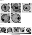
- FIG. 11 shows TEM images of hollow mesoporous organic silica nano/microparticles having various types of metal particles deposited thereon prepared according to the present disclosure.
- FIG. 11 it may be seen that a) in FIG. 11 is a hollow mesoporous organic silica nanoparticle having spherical gold particles and magnetic nanoparticles deposited thereon, b) is a hollow mesoporous organic silica nanoparticle having nanoroad-shaped gold particles and magnetic nanoparticles deposited thereon, and c) is a hollow mesoporous organic silica nanoparticle having nanocube-shaped gold particles and magnetic nanoparticles deposited thereon.
- the hollow mesoporous organic silica nanoparticle having the metal particles deposited thereon prepared using the preparation method of the present disclosure may have the metal particles and the magnetic nanoparticles having various shapes deposited thereon.
- the nanoparticle prepared using the method for preparing the hollow mesoporous organic silica nanoparticle having the metal particles deposited thereon of the present disclosure is very remarkable in terms of the shape of the deposited metal nanoparticles compared to that prepared using the conventional nanoparticle synthesis method.
- various shapes of metal nanoparticles that have already been synthesized may be deposited.
- the present disclosure has a very high applicability to a medical field by introducing additional metal nanoparticles capable of performing various functions such as a biocatalytic reaction, an MRI, and the like by depositing not only the gold nanoparticle, but also a metal nanoparticles having a completely different function.
- the mesoporous organic silica nanoparticle having such metal particles deposited thereon has great significance in enabling complex functions to be implemented in the single nanoparticle structure.
- the metal particles may be deposited while varying the concentration thereof based on the preparation according to the method for preparing the hollow mesoporous organic silica nanoparticle having the metal particles deposited thereon of the present disclosure, a description will be made with reference to FIG. 11 .
- FIG. 12 shows TEM images of a hollow mesoporous organic silica nano/microparticle having metal particles with an increased content deposited thereon.
- the nanoparticle was prepared by increasing the content of the injected metal particles from 0 to 21.95 ⁇ mol through the preparation method according to the present disclosure, and an increased amount of metal particles is deposited as an amount of the injected metal increases.
- concentration of the metal particles may be precisely controlled.
- the hollow mesoporous organic silica nanoparticle having the metal particles deposited thereon of the present disclosure may have various inorganic nanoparticles deposited inside the hollow, because an oil material may be post-encapsulated through the mesoporous organic silica layer, the hollow mesoporous organic silica nanoparticle having the metal particles deposited thereon of the present disclosure may be applied as a photo-stimulative drug releasing material of micron to submicron size by combining a photothermal effect of the metal particles and a phase change function based on a temperature of a phase change material (hereinafter, PCM) with each other.
- PCM phase change material
- FIG. 13 is a view related to a photo-stimulative drug releasing material using a hollow mesoporous organic silica nano/microparticle prepared according to the present disclosure.
- a) in FIG. 13 is a schematic diagram of a preparation process of a photo-stimulative drug releasing material using a hollow mesoporous organic silica nanoparticle prepared according to the present disclosure.
- b) in FIG. 13 is a diagram showing utilization of a photo-stimulative drug releasing material using a hollow mesoporous organic silica nanoparticle prepared according to the present disclosure.
- the hollow mesoporous organic silica nanoparticle having the gold particles and the magnetic particles deposited thereon prepared according to the present disclosure may be utilized as the photo-stimulative drug releasing material by encapsulating an anti-cancer substance dissolved in the liquid PCM into the mesoporous organic silica layer through the mesoporous organic silica shell at an elevated temperature of about 60° C., and then cooling the anti-cancer substance at room temperature to change a phase of the PCM to solid.
- the PCM has the solid phase at about 36° C., which is a human body temperature, even when being injected into cancer cells, the encapsulated anti-cancer substance is not released to the outside through the meso pores.
- the hollow mesoporous organic silica nanoparticle having the gold particles and the magnetic particles deposited thereon irradiates NIR to increase a temperature of the by about 45° C. or more to change the phase of the PCM to liquid, and thus, allows the internal drug to be released to the outside, so that the hollow mesoporous organic silica nanoparticle having the gold particles and the magnetic particles deposited thereon is utilized as the drug releasing material.
- the phase of the PCM is changed back to the solid as the temperature drops to the body temperature, and thus, the drug release stops.
- the hollow mesoporous organic silica nanoparticle having the gold particles and the magnetic particles deposited thereon may be used as the photo-stimulative drug releasing material that may selectively adjust the drug release by irradiating the NIR as needed.
- the magnetic particles that may be selectively deposited may be used in a variety of purposes, such as tracking or visualization of substances through the MRI, recovery using the magnet, or the like.
- hollow mesoporous organic silica nanoparticle having the metal particles deposited thereon prepared according to the present disclosure may be utilized as a micro reactor in which heterogeneous inorganic catalysts are encapsulated will be described with a specific approach through FIG. 14 .
- FIG. 14 is a view showing utilization as a tandem micro reactor of a hollow mesoporous organic silica nano/microparticle having metal particles deposited thereon according to the present disclosure.
- the hollow mesoporous organic silica nano/microparticle having the metal particles deposited thereon prepared according to the present disclosure may be used as a tandem catalyst by depositing the heterogeneous inorganic catalysts into one hollow micro-reactor. Therefore, it may be identified that it is possible to construct a microreactor capable of catalyzing two or more chemical reactions in a complementary relationship at a micron level.
Landscapes
- Chemical & Material Sciences (AREA)
- Engineering & Computer Science (AREA)
- Organic Chemistry (AREA)
- Chemical Kinetics & Catalysis (AREA)
- Materials Engineering (AREA)
- Health & Medical Sciences (AREA)
- Bioinformatics & Cheminformatics (AREA)
- Public Health (AREA)
- Animal Behavior & Ethology (AREA)
- Veterinary Medicine (AREA)
- General Health & Medical Sciences (AREA)
- Life Sciences & Earth Sciences (AREA)
- Medicinal Chemistry (AREA)
- Pharmacology & Pharmacy (AREA)
- Epidemiology (AREA)
- Optics & Photonics (AREA)
- Physics & Mathematics (AREA)
- Nanotechnology (AREA)
- Biomedical Technology (AREA)
- Dispersion Chemistry (AREA)
- Inorganic Chemistry (AREA)
- Silicates, Zeolites, And Molecular Sieves (AREA)
- Catalysts (AREA)
- Silicon Compounds (AREA)
Abstract
Description
-
- d) in
FIG. 11 is an image of a hollow mesoporous organic silica nanoparticle having nanocube-shaped palladium and magnetic nanoparticles. It may be seen from d) that not only the gold particles but also various kinds of metal particles may be deposited. - e) in
FIG. 11 shows a composite hollow mesoporous organic silica nanoparticle having not only magnetic nanoparticles and spherical gold nanoparticles, but also a palladium nanocubes simultaneously deposited thereon.
- d) in
Claims (20)
Applications Claiming Priority (3)
| Application Number | Priority Date | Filing Date | Title |
|---|---|---|---|
| KR1020190025726A KR102189426B1 (en) | 2019-03-06 | 2019-03-06 | Mesoporous hollow organosilica loaded with metal nanoparticles, and producing method of the same |
| KR10-2019-0025726 | 2019-03-06 | ||
| PCT/KR2020/002546 WO2020180029A1 (en) | 2019-03-06 | 2020-02-21 | Metal particle-loaded hollow mesoporous organosilica nano/microparticles and method for manufacturing same |
Publications (2)
| Publication Number | Publication Date |
|---|---|
| US20220023841A1 US20220023841A1 (en) | 2022-01-27 |
| US12102985B2 true US12102985B2 (en) | 2024-10-01 |
Family
ID=72337297
Family Applications (1)
| Application Number | Title | Priority Date | Filing Date |
|---|---|---|---|
| US17/312,246 Active 2041-05-18 US12102985B2 (en) | 2019-03-06 | 2020-02-21 | Metal particle-loaded hollow mesoporous organosilica nano/microparticles and method for manufacturing same |
Country Status (3)
| Country | Link |
|---|---|
| US (1) | US12102985B2 (en) |
| KR (1) | KR102189426B1 (en) |
| WO (1) | WO2020180029A1 (en) |
Families Citing this family (8)
| Publication number | Priority date | Publication date | Assignee | Title |
|---|---|---|---|---|
| KR102411087B1 (en) * | 2021-04-27 | 2022-06-22 | 금오공과대학교 산학협력단 | Manufacturing method of gold nanorods coated mesoporous silica layer using alcohol |
| CN113893831A (en) * | 2021-10-28 | 2022-01-07 | 复旦大学 | Magnetic nano-rod with ordered large mesoporous polymer shell and synthesis method thereof |
| KR102830131B1 (en) * | 2022-09-08 | 2025-07-03 | 부산대학교 산학협력단 | Triplet-triplet annihilation-based upconversion fluorescent material supported nanocapsule and method for manufacturing the same |
| KR102863847B1 (en) | 2022-09-30 | 2025-09-25 | 서강대학교산학협력단 | Mesoporous organosilica nanocomposite capable of mulitiple stimuli responsive drug release and muti modal cancer treatments and method for preparing the same |
| CN115770589B (en) * | 2022-11-24 | 2024-09-20 | 中国科学院深圳先进技术研究院 | Ultra-small stable platinum cobalt nanoparticle catalyst, preparation method thereof and application thereof in selective hydrogenation |
| KR102778980B1 (en) * | 2022-12-05 | 2025-03-07 | 경희대학교 산학협력단 | Radiative cooling material based on porous nanoparticles and radiative cooling device using the same |
| CN116387007B (en) * | 2023-04-14 | 2024-01-02 | 西华大学 | Preparation method of synthetic oil-based magnetorheological fluid with high dispersion stability |
| CN121219235A (en) * | 2023-05-30 | 2025-12-26 | 青岛比恩贸易有限公司 | Hollow mesoporous silica rods, methods for their preparation, and methods for loading active materials |
Family Cites Families (3)
| Publication number | Priority date | Publication date | Assignee | Title |
|---|---|---|---|---|
| KR101087260B1 (en) * | 2009-06-23 | 2011-11-29 | 한국외국어대학교 연구산학협력단 | Hollow mesoporous silica capsules and preparation method thereof |
| KR101627931B1 (en) * | 2014-09-25 | 2016-06-08 | 단국대학교 천안캠퍼스 산학협력단 | Magnetic CNT Hybrid Nanocarrier Ensheathed with Mesoporous Silica for Drug Delivery and Imaging |
| KR101725240B1 (en) * | 2015-03-24 | 2017-04-11 | 부산대학교 산학협력단 | DUAL STIMULI-RESPONSIVE CORE-SHELL MAGNETIC NANOPARTICLE HAVING UV-LIGHT RESPONSIVITY AND pH-RESPONSIVITY, AND DRUG DELIVERY COMPISING THE SAME |
-
2019
- 2019-03-06 KR KR1020190025726A patent/KR102189426B1/en active Active
-
2020
- 2020-02-21 US US17/312,246 patent/US12102985B2/en active Active
- 2020-02-21 WO PCT/KR2020/002546 patent/WO2020180029A1/en not_active Ceased
Non-Patent Citations (5)
| Title |
|---|
| English translation of Written Opinion for International Application No. PCT/KR2020/002546 mailed on Jun. 9, 2020. |
| International Search Report and Written Opinion corresponding to International Application No. PCT/KR2020/002546 mailed on Jun. 9, 2020 with English translation of the International Search Report. |
| Liberman et al, Synthesis and Surface Functionalization of Silica Nanoparticles for Nanomedia, Surf Sci Rep, 6992-3): 132-158 (Year: 2014). * |
| Wei et al, A Versatile In-Situ Etching-Growth Strategy for Synthesis of Yolk-Shell Structured Periodic Mesoporous Organosilica Nanocomposites, RSC Advances, vol. 6, pp. 51470-51479. (Year: 2016). * |
| Wei, Y. et al. "A versatile in situ etching-growth strategy for synthesis of yolk-shell structured periodic mesoporous organosilica nanocomposites" RSC Advances, 2016, vol. 6, pp. 51470-051479. |
Also Published As
| Publication number | Publication date |
|---|---|
| US20220023841A1 (en) | 2022-01-27 |
| WO2020180029A1 (en) | 2020-09-10 |
| KR20200107122A (en) | 2020-09-16 |
| KR102189426B1 (en) | 2020-12-11 |
Similar Documents
| Publication | Publication Date | Title |
|---|---|---|
| US12102985B2 (en) | Metal particle-loaded hollow mesoporous organosilica nano/microparticles and method for manufacturing same | |
| Gao et al. | Encapsulated metal nanoparticles for catalysis | |
| Pérez‐Lorenzo et al. | Hollow‐Shelled Nanoreactors Endowed with High Catalytic Activity | |
| Jia et al. | Colloidal metal nanoparticles as a component of designed catalyst | |
| Zhu et al. | A new strategy for the surface-free-energy-distribution induced selective growth and controlled formation of Cu 2 O–Au hierarchical heterostructures with a series of morphological evolutions | |
| El-Safty et al. | Organic–inorganic mesoporous silica nanostrands for ultrafine filtration of spherical nanoparticles | |
| Guo et al. | Fabrication of Co@ SiO 2@ C/Ni submicrorattles as highly efficient catalysts for 4-nitrophenol reduction | |
| Gu et al. | Facile and controllable fabrication of gold nanoparticles-immobilized hollow silica particles and their high catalytic activity | |
| Dong et al. | A general and eco-friendly self-etching route to prepare highly active and stable Au@ metal silicate yolk-shell nanoreactors for catalytic reduction of 4-nitrophenol | |
| Yao et al. | Simultaneous chemical modification and structural transformation of stober silica spheres for integration of nanocatalysts | |
| WO2017134493A1 (en) | Synthesis of fibrous nano-silica spheres with controlled particle size, fibre density, and various textural properties | |
| Chen et al. | Shape-controlled synthesis of ruthenium nanocrystals and their catalytic applications | |
| Sun et al. | A Shell‐by‐Shell Approach for Synthesis of Mesoporous Multi‐Shelled Hollow MOFs for Catalytic Applications | |
| Sun et al. | Controllable integration of ultrasmall noble metal nanoparticles into mesoporous silica matrixes by a self-assembly method | |
| Liu et al. | Cu 2 O-directed in situ growth of Au nanoparticles inside HKUST-1 nanocages | |
| Yang et al. | Developing a general method for encapsulation of metal oxide nanoparticles in mesoporous silica shell by unraveling its formation mechanism | |
| Choi et al. | Inorganic shell nanostructures to enhance performance and stability of metal nanoparticles in catalytic applications | |
| Safari et al. | Encapsulation of metal nanoparticles (MNPs) as catalyst | |
| Tran et al. | Recent strategies for constructing hierarchical multicomponent nanoparticles/metal–organic framework hybrids and their applications | |
| Mekawy et al. | Mesoporous silica hybrid membranes for precise size-exclusive separation of silver nanoparticles | |
| Zhao et al. | Convenient hydrothermal treatment combining with “Ship in Bottle” to construct Yolk-Shell N-Carbon@ Ag-void@ mSiO2 for high effective Nano-Catalysts | |
| Zhan | Synthetic architecture of integrated nanocatalysts with controlled spatial distribution of metal nanoparticles | |
| Hou et al. | Highly efficient, stable and controllable multi-core, rattle-type Ag@ SiO 2 catalyst for the reduction of 4-nitrophenol | |
| Xuan et al. | Immobilization of Pd nanocatalysts on magnetic rattles and their catalytic property | |
| Wang et al. | Tailored synthesis of various Au nanoarchitectures with branched shapes |
Legal Events
| Date | Code | Title | Description |
|---|---|---|---|
| FEPP | Fee payment procedure |
Free format text: ENTITY STATUS SET TO UNDISCOUNTED (ORIGINAL EVENT CODE: BIG.); ENTITY STATUS OF PATENT OWNER: SMALL ENTITY |
|
| AS | Assignment |
Owner name: PUSAN NATIONAL UNIVERSITY INDUSTRY UNIVERSITY COOPERATION FOUNDATION, KOREA, REPUBLIC OF Free format text: ASSIGNMENT OF ASSIGNORS INTEREST;ASSIGNORS:KIM, JAE HYUK;LEE, HAK LAE;REEL/FRAME:056508/0432 Effective date: 20210610 |
|
| FEPP | Fee payment procedure |
Free format text: ENTITY STATUS SET TO SMALL (ORIGINAL EVENT CODE: SMAL); ENTITY STATUS OF PATENT OWNER: SMALL ENTITY |
|
| STPP | Information on status: patent application and granting procedure in general |
Free format text: NON FINAL ACTION MAILED |
|
| STPP | Information on status: patent application and granting procedure in general |
Free format text: RESPONSE TO NON-FINAL OFFICE ACTION ENTERED AND FORWARDED TO EXAMINER |
|
| STPP | Information on status: patent application and granting procedure in general |
Free format text: NOTICE OF ALLOWANCE MAILED -- APPLICATION RECEIVED IN OFFICE OF PUBLICATIONS |
|
| ZAAB | Notice of allowance mailed |
Free format text: ORIGINAL CODE: MN/=. |
|
| STPP | Information on status: patent application and granting procedure in general |
Free format text: PUBLICATIONS -- ISSUE FEE PAYMENT VERIFIED |
|
| STCF | Information on status: patent grant |
Free format text: PATENTED CASE |