US12099145B2 - SPAD array with ambient light suppression for solid-state LiDAR - Google Patents
SPAD array with ambient light suppression for solid-state LiDAR Download PDFInfo
- Publication number
- US12099145B2 US12099145B2 US17/144,115 US202117144115A US12099145B2 US 12099145 B2 US12099145 B2 US 12099145B2 US 202117144115 A US202117144115 A US 202117144115A US 12099145 B2 US12099145 B2 US 12099145B2
- Authority
- US
- United States
- Prior art keywords
- macro
- pixels
- laser
- column
- photodetector
- Prior art date
- Legal status (The legal status is an assumption and is not a legal conclusion. Google has not performed a legal analysis and makes no representation as to the accuracy of the status listed.)
- Active, expires
Links
- 230000001629 suppression Effects 0.000 title abstract description 7
- 238000000034 method Methods 0.000 claims abstract description 28
- 238000001514 detection method Methods 0.000 claims description 5
- 230000009467 reduction Effects 0.000 abstract description 3
- 230000008569 process Effects 0.000 description 8
- 230000015654 memory Effects 0.000 description 7
- 238000004590 computer program Methods 0.000 description 3
- 239000007787 solid Substances 0.000 description 3
- 238000005286 illumination Methods 0.000 description 2
- 238000003384 imaging method Methods 0.000 description 2
- 230000007246 mechanism Effects 0.000 description 2
- 230000003287 optical effect Effects 0.000 description 2
- 230000002123 temporal effect Effects 0.000 description 2
- 230000009471 action Effects 0.000 description 1
- 238000003491 array Methods 0.000 description 1
- 230000008901 benefit Effects 0.000 description 1
- 230000005540 biological transmission Effects 0.000 description 1
- 230000005611 electricity Effects 0.000 description 1
- 238000001914 filtration Methods 0.000 description 1
- 238000012986 modification Methods 0.000 description 1
- 230000004048 modification Effects 0.000 description 1
- 230000002085 persistent effect Effects 0.000 description 1
- 230000035945 sensitivity Effects 0.000 description 1
- 239000000126 substance Substances 0.000 description 1
Images


Classifications
-
- G—PHYSICS
- G01—MEASURING; TESTING
- G01S—RADIO DIRECTION-FINDING; RADIO NAVIGATION; DETERMINING DISTANCE OR VELOCITY BY USE OF RADIO WAVES; LOCATING OR PRESENCE-DETECTING BY USE OF THE REFLECTION OR RERADIATION OF RADIO WAVES; ANALOGOUS ARRANGEMENTS USING OTHER WAVES
- G01S7/00—Details of systems according to groups G01S13/00, G01S15/00, G01S17/00
- G01S7/48—Details of systems according to groups G01S13/00, G01S15/00, G01S17/00 of systems according to group G01S17/00
- G01S7/483—Details of pulse systems
- G01S7/486—Receivers
- G01S7/4861—Circuits for detection, sampling, integration or read-out
- G01S7/4863—Detector arrays, e.g. charge-transfer gates
-
- G—PHYSICS
- G01—MEASURING; TESTING
- G01S—RADIO DIRECTION-FINDING; RADIO NAVIGATION; DETERMINING DISTANCE OR VELOCITY BY USE OF RADIO WAVES; LOCATING OR PRESENCE-DETECTING BY USE OF THE REFLECTION OR RERADIATION OF RADIO WAVES; ANALOGOUS ARRANGEMENTS USING OTHER WAVES
- G01S17/00—Systems using the reflection or reradiation of electromagnetic waves other than radio waves, e.g. lidar systems
- G01S17/02—Systems using the reflection of electromagnetic waves other than radio waves
- G01S17/06—Systems determining position data of a target
- G01S17/08—Systems determining position data of a target for measuring distance only
- G01S17/10—Systems determining position data of a target for measuring distance only using transmission of interrupted, pulse-modulated waves
-
- G—PHYSICS
- G01—MEASURING; TESTING
- G01S—RADIO DIRECTION-FINDING; RADIO NAVIGATION; DETERMINING DISTANCE OR VELOCITY BY USE OF RADIO WAVES; LOCATING OR PRESENCE-DETECTING BY USE OF THE REFLECTION OR RERADIATION OF RADIO WAVES; ANALOGOUS ARRANGEMENTS USING OTHER WAVES
- G01S7/00—Details of systems according to groups G01S13/00, G01S15/00, G01S17/00
- G01S7/48—Details of systems according to groups G01S13/00, G01S15/00, G01S17/00 of systems according to group G01S17/00
- G01S7/481—Constructional features, e.g. arrangements of optical elements
- G01S7/4817—Constructional features, e.g. arrangements of optical elements relating to scanning
-
- G—PHYSICS
- G01—MEASURING; TESTING
- G01S—RADIO DIRECTION-FINDING; RADIO NAVIGATION; DETERMINING DISTANCE OR VELOCITY BY USE OF RADIO WAVES; LOCATING OR PRESENCE-DETECTING BY USE OF THE REFLECTION OR RERADIATION OF RADIO WAVES; ANALOGOUS ARRANGEMENTS USING OTHER WAVES
- G01S7/00—Details of systems according to groups G01S13/00, G01S15/00, G01S17/00
- G01S7/48—Details of systems according to groups G01S13/00, G01S15/00, G01S17/00 of systems according to group G01S17/00
- G01S7/483—Details of pulse systems
- G01S7/486—Receivers
- G01S7/487—Extracting wanted echo signals, e.g. pulse detection
Definitions
- Embodiments of the present invention relate generally to remote sensing, and more particularly relate to a method of ambient light suppression by selectively turning off portions of a photodetector, and using a multi-level digital signal for signal triggering.
- a LiDAR device can measure distances to objects in an environment by illuminating the objects with laser pulses and measuring reflected pulses from the objects.
- LiDAR devices typically utilizes high-grade optics and a rotating assembly to create a wide field of view, but such implementation tends to be bulky and costly.
- Solid-state Lidar sensors tend to be less costly but still may have large dimensions.
- Solid State LiDAR devices tend to use single photon avalanche diodes (SPAD), which has high photon sensitivity.
- SPADs are also prone to ambient light.
- histogram binning can be used to remove ambient light can improve signal to noise rations, but may need a large number of illuminations to generate a usable histogram. Thus the approach is energy inefficient.
- the LiDAR device can be configured to scan laser pulses in such a manner that reflected laser pulses are incident on one column of macro-pixels at a time in a macro-pixel array on the photodetector, where only that column is turned on, and the rest of the columns are turned off.
- the LiDAR device can further be configured to scan at different angles such that laser pulses from a same portion of a target object can be incident on the turned-on column multiple times to increase the resolution of a LiDAR image.
- outputs from multiple SPADs in a max-pixel are concatenated to form a multi-level digital signal, and a threshold can be used for discarding or registering the multi-level digital signal for further noise reduction.
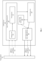
- FIG. 1 illustrates an example LiDAR device in which embodiments of the invention can be implemented in accordance with an embodiment.
- FIG. 2 shows a system for suppressing ambient light on a LiDAR photodetector in accordance with an embodiment.
- FIGS. 3 A- 3 B illustrate examples of a multi-level digital signal and an example of a threshold value in accordance with an embodiment.
- FIG. 4 illustrates further the system for suppressing ambient light in accordance with an embodiment.
- FIG. 5 is a process 500 illustrating a method of suppressing ambient light in a LiDAR device in accordance with an embodiment.
- the LiDAR device can be configured to scan laser pulses in such a manner that reflected laser pulses are incident on one column of macro-pixels at a time in a macro-pixel array on the photodetector, where only that column is turned on, and the rest of the columns are turned off.
- the LiDAR device can further be configured to scan at different angles such that laser pulses from a same portion of a target object can be incident on the turned-on column multiple times to increase the resolution of a LiDAR image.
- outputs from multiple SPADs in a max-pixel are concatenated to form a multi-level digital signal, and a threshold can be used for discarding or registering the multi-level digital signal for further noise reduction.
- a system for suppressing ambient light in a light detection and ranging (LiDAR) device comprises a photodetector including a plurality of macro-pixels forming a macro-pixel array, each macro-pixel in the photodetector including a number of single photon avalanche diodes (SPAD); a laser scanner to scan laser beams at different directions; and a controlling unit that configures the laser scanner to scan laser beams such that reflected laser photons are incident on the photodetector one column of macro-pixels at a time, the column of macro-pixels being turned on, and the rest of the macro-pixels on the photodetector being turned off.
- a photodetector including a plurality of macro-pixels forming a macro-pixel array, each macro-pixel in the photodetector including a number of single photon avalanche diodes (SPAD); a laser scanner to scan laser beams at different directions; and a controlling unit that configures the laser scanner to scan laser
- the system further comprises a number of adders, each adder configured to read photons from one macro-pixel of the turned-on column of macro-pixels, and construct a multi-level digital signal.
- the photons read from the macro-pixel include one or more signal photons and one or more noise photons.
- the controlling unit is further configured to register the multi-level digital signal based on a predetermined threshold.
- the laser scanner is configured to scan for a predetermined number of times, each time at a different angle, such that the turned-on column of macro-pixels receives reflected laser pulses of a same portion of a target object from different angles.
- the laser scanner is configured to scan for a predetermined number of times, each time at a same angle, such that the turned-on column of macro-pixels receives reflected laser pulses of a same portion of a target object from the same angle.
- the controlling unit is configured to read photons from the turned-on column of macro-pixels by using adders to construct multi-level digital signals or without.
- the laser beams are linear laser beams that are either diffused from laser spots by a diffuser in the LiDAR device, or directly generated by a laser pulse emitting unit in the LiDAR device.
- the embodiments can above be practiced as methods, and can include non-transitory machine readable media that store executable computer program instructions that can cause one or more data processing systems to perform the one or more methods described herein when the computer program instructions are executed by the one or more data processing systems.
- the instructions can be stored in non-volatile memory such as flash memory or other forms of memory.
- a sequence of the operations of a method in the embodiments of the present invention may be adjusted, and certain operations may also be combined or removed according to an actual requirement.
- FIG. 1 illustrates an example of a LiDAR device 101 in which embodiments of the invention can be implemented in accordance with an embodiment.
- the LiDAR device 101 can be a solid state LiDAR device 101 , which can measure distances to objects in an environment by illuminating the objects with laser pulses (laser beams). Differences in return times of the reflected laser pulses and wavelengths can be used to create a point cloud of the environment.
- the point cloud can provide spatial location and depth information, for use in identifying and tracking the objects.
- the LiDAR device 101 can include a laser pulse emitting unit 104 , a laser pulse scanner 105 , a laser pulse receiving unit 109 , and a controlling unit 107 .
- the laser pulse emitting unit 104 can include one or more laser emitters that emit beams of short pulses of laser light including photons of various frequencies.
- the laser pulse emitting unit can emit laser spots or linear laser beams.
- a diffuser can be used to increase the size of laser spots, including changing the shape of the laser spots into desired laser beams.
- the laser pulse emitting unit 104 can project linear laser beams.
- the laser pulse emitting unit 104 uses a number of fast axis collimators (FACs) to collimate laser beams from a laser source array, a cylinder lens array for converting the collimated laser beams to parallel laser beams, and a prism array pair for reducing the pitch of the parallel laser beams.
- the laser pulse emitting unit 104 can further includes a first cylinder lens for focusing the laser beams from the prism array pair onto a MEMS mirror, which redirects the laser beams as a linear laser beam towards a predetermined direction.
- the laser pulse emitting unit 104 emits outgoing laser beams 113 .
- the beam of outgoing laser beams 113 can be steered or scanned by the laser pulse scanner 105 in one or more directions using a variety of mechanisms, including microelectromechanical system (MEMS) mirrors, and one or more optical phased arrays (OPA).
- MEMS microelectromechanical system
- OPA optical phased arrays
- Each of the one or more directions is referred to as a steering direction or a scanning direction.
- a vertical angle and a horizontal angle associated with each steering direction is referred to as a steering angle or a scanning angle respectively.
- the laser pulse scanner 105 can steer one or more beams of laser pulses in a steering direction.
- Each beam of laser pulses can have a fixed number of pulses.
- the controlling unit 107 can include control logic implemented in hardware, software, firmware, or a combination thereof.
- the controlling logic 107 can drive the other units or subsystems 104 , 105 and 109 of the LiDAR device 101 in a coordinated manner, and can execute one or more data processing algorithms to perform one or more operations for signal filtering, object detections, and image processing.
- the controlling unit 107 can synchronize the laser pulse emitting unit 104 and the laser pulse scanner 105 so that the scanner pulse scanner 105 can scan a horizontal field of view in multiple lines or at a particular direction.
- the laser light receiving unit 109 can collect one or more beams of laser beams (e.g., laser beams 112 ) reflected from a target object 103 using one or more imaging lens (e.g., imaging lens 115 ), and focus the beams of laser pulses a photodetector 117 , which can include multiple high-sensitivity photodiodes.
- the photodetectors can convert photons in the reflected laser pulses into electricity, and send returned signals incident on the photodetector 117 to the controlling unit 107 for processing.
- laser diodes in the laser pulse emitting unit 104 can operate in a pulsed mode with a pulse repeating at a fixed interval (e.g., every few micro-seconds).
- the laser diodes and laser drive circuits for providing appropriate bias and modulation currents for the laser diodes can be chosen according to predetermined performance parameters of the LiDAR device 101 . Examples of the performance parameters can include a required maximum range of scanned space and resolution.
- FIG. 2 shows a system for suppressing ambient light on a LiDAR photodetector in accordance with an embodiment.
- the photodetector 117 includes multiple macro-pixels, which form a macro-pixel array.
- a macro-pixel is also referred to as a max pixel.
- the macro-pixel array can include 12 macro-pixels, with each macro-pixel including 9 SPADs.
- the 12 macro-pixels are arranged in 3 rows of macro-pixels and 4 columns of macro-pixels 220 , 222 , 224 , and 225 .
- Macro-pixels in each row is connected by a bus, with an adder attached to the bus.
- adder 1 213 is attached to a bus 220 connecting the first row of macro-pixels
- adder B 215 is attached to a bus connecting the second row of macro-pixels
- adder C is attached to a bus connecting the third row of macro-pixels. All the macro-pixels in the photodetector 117 can be connected together through the different buses or the adders.
- the laser pulse scanner unit 105 of the LiDAR device 101 can be configured by the controlling unit 107 to scan laser pulses in such a manner that reflected laser pulses from a target object are incident on the macro-pixel array one column at a time from left to right column.
- the reflected laser pulses can be incident on column A 220 first, then on column B 222 , followed by column C 224 and column D 226 .
- the controlling unit 107 can dynamically turn on and turn off each column of macro-pixels, depending on which column is to receive reflected pulses. In one embodiment, the controlling unit 107 can turn on only that column of macro pixels that is to receive reflected laser pulses; and turn off the other columns of macro pixels on the photodetectors 117 .
- the signal to noise ratio of the LiDAR device 101 can be improved, since the turned-off macro pixels cannot receive any photons, including ambient photons.
- the turned-off macro-pixels are not expected to receive any photons due to the reflection from the illumination in the particular scan shown in FIG. 2 . Therefore, any photons incident on those macro-pixels would be noises had they not been turned off.
- FIG. 2 shows that column A 220 of macro pixels is turned on and is receiving reflected signals. Therefore, only column A 220 is turned on, and the rest of the columns (columns 222 , 224 , and 226 ) are turned off. However, in another point of time, when column B 222 is receiving reflected laser signals from a corresponding scanning angle, column A 220 would be turned off, and column C 224 and column D 226 will remain off. In the whole photodetector, only column B 222 would be on.
- each macro pixel can receive one or more photons representing real signals reflected from the target object, and one or more noise photons.
- a macro pixel 201 can receive signal photons 217 , 218 and 219 ; and one noise photon 221 from ambient light.
- the controlling unit 107 or adder 1 213 can convert all the photons 217 , 218 , 219 and 221 that are incident on the macro-pixel 201 into electrical signal. Since the photons 217 , 218 , 219 and 221 could arrive at a slightly different time, the output of adder 1 213 is a multi-level digital signal. In the embodiment as shown in FIG. 2 , a four-level digital signal would be constructed from the four photons, including the noise photon 217 , that are received on the macro-pixel 201 .
- the controlling unit 107 can apply a predetermined threshold value to the four-level digital signal.
- the threshold value can be used to determine whether to register the four-level digital signal as a signal event or discard it as a noise event.
- the threshold value can be set 3.5. Therefore, the controlling unit 107 can register the four-level digital signal as a signal event because the number of levels representing the number of photons is equal to or more than the threshold value.
- Another macro-pixel 222 can receive two noise photons 226 and 228 from ambient light, and one signal photon 224 .
- a three-level digital event constructed by the controlling unit 107 from the macro-pixel 222 would be rejected as a noise event because the multi-level digital event does not reach the threshold of 3.5.
- controlling unit 107 is configured to read photons from the turned-on column of macro-pixels without using adders 213 , 215 and 217 to construct multi-level digital signals.
- FIGS. 3 A- 3 B illustrate examples of multi-level digital signals and an example of a threshold value in accordance with an embodiment.
- FIG. 3 A uses the macro-pixel 201 and adder 1 213 as an example.
- Adder 1 213 can be part of a circuit for signal processing or a separate circuit in the controlling unit 107 .
- Adder 1 213 can count 4 photons 217 - 221 from reflected laser pulses from a particular scanning angle of the LiDAR device 101 .
- the controlling unit 107 can control the laser pulse scanner 105 to scan at different angles at regular intervals of time, for example, every 600 nanoseconds. After a short delay (e.g., 100 nanoseconds) after each scan, photons from the scanning angle are expected to be incident on photodetector 117 . Therefore, the controlling unit 107 can calculate when a particular column of macro-pixels is to receive reflected photons.
- the column 220 of macro-pixels containing the macro-pixel 201 is to receive reflected photons.
- the controlling unit 107 can turn on this column 220 of macro-pixels, and turn off all the other columns of macro-pixels 222 , 224 and 226 . Therefore, signal photons that the photodetector 117 is expected to receive are incident on the photodetector 117 in a temporal cluster—they arrive at approximately the same time, which means the larger the number of photons received on a macro-pixel, the more likely that the photons are signal photons.
- a threshold value can be used to determine which multi-level digital signal is a noise event, and which one is a signal event. For example, if a particular macro-pixel receives only one photon, it is likely that the photon is a random noise photon because signal photons are expected to be incident on the macro-pixel in a temporal cluster.
- a threshold value 317 of 3.5 can be applied to a multi-level digital signal 319 constructed by add A 213 from the 4 photons received on the macro-pixel 201 .
- adder 1 213 can register the multi-level digital signal as a signal event because the number of levels of the multi-level digital signal is equal to or exceeds the threshold value of 3.5.
- FIG. 3 B uses the macro-pixel 222 and adder 2 215 as an example. As shown in FIG. 3 B , a three-level digital signal 321 converted from photons incident on the macro-pixel 222 does not reach the threshold value 317 , and therefore would be rejected by the controlling unit 107 as a noise event.
- FIG. 4 further illustrates the system for suppressing ambient light in accordance with an embodiment. More specifically, this figures describes features that can be used to compensate for the resolution loss due to the use of macro-pixels in the photodetector 117 and the potential discarding of signal photons as noise photons.
- the photodetector 117 arranges the SPADS in macro-pixels, resulting in less pixels compared to photodetectors that register a pixel per SPAD. Further, the use of a threshold value may potentially cause some signal photons to be discarded. The above factors may reduce the resolution of a LiDAR image.
- the controlling unit 107 can control the laser pulse scanner 105 to scan at slightly different angles 401 , 403 and 405 , and each scan may cause reflected photons from a same portion of a target object to be incident on column A 220 .
- the controlling unit 107 can use the adders 213 , 215 , and 217 to construct a multi-level digital signal for each macro-pixel in column A 220 , and determines to register or discard it based on the number of levels of that multi-level digital signal.
- Each scan can result in additional information of the target object, and the signal photons from all the scans can be added together to improve the resolution of the LiDAR image.
- the different scans can be directed towards the same angle.
- the reflected laser pulses (reflected laser photons) from the different scans are incident on column A 220 .
- Such multiple scans towards the same angle may also increase the resolution of the LiDAR image.
- FIG. 5 is a process 500 illustrating a method of suppressing ambient light in a LiDAR device in accordance with an embodiment.
- Process 500 may be performed by processing logic which may include software, hardware, firmware, or a combination thereof.
- processing logic may include software, hardware, firmware, or a combination thereof.
- process 500 may be performed by the controlling unit 107 described in FIG. 1 .
- the processing logic sends a command to instruct a laser scanner of the LiDAR device to scan laser beams at a particular angle.
- the processing logic turns on a column of max-pixels on a photodetector of the LiDAR device, the photodetector including a plurality of macro-pixels forming a macro-pixel array, each macro-pixel in the photodetector including a number of single photon avalanche diodes (SPAD), and turns off the rest of the columns of macro-pixels on the photodetector.
- the processing logic reads reflected photons from the particular angle that are incident on the column of max-pixels on the photodetector of the LiDAR device.
- components as shown and described above may be implemented in software, hardware, or a combination thereof.
- such components can be implemented as software installed and stored in a persistent storage device, which can be loaded and executed in a memory by a processor (not shown) to carry out the processes or operations described throughout this application.
- such components can be implemented as executable code programmed or embedded into dedicated hardware such as an integrated circuit (e.g., an application specific IC or ASIC), a digital signal processor (DSP), or a field programmable gate array (FPGA), which can be accessed via a corresponding driver and/or operating system from an application.
- an integrated circuit e.g., an application specific IC or ASIC
- DSP digital signal processor
- FPGA field programmable gate array
- such components can be implemented as specific hardware logic in a processor or processor core as part of an instruction set accessible by a software component via one or more specific instructions.
- Embodiments of the disclosure also relate to an apparatus for performing the operations herein.
- a computer program is stored in a non-transitory computer readable medium.
- a machine-readable medium includes any mechanism for storing information in a form readable by a machine (e.g., a computer).
- a machine-readable (e.g., computer-readable) medium includes a machine (e.g., a computer) readable storage medium (e.g., read only memory (“ROM”), random access memory (“RAM”), magnetic disk storage media, optical storage media, flash memory devices).
- processing logic that comprises hardware (e.g. circuitry, dedicated logic, etc.), software (e.g., embodied on a non-transitory computer readable medium), or a combination of both.
- processing logic comprises hardware (e.g. circuitry, dedicated logic, etc.), software (e.g., embodied on a non-transitory computer readable medium), or a combination of both.
- Embodiments of the present disclosure are not described with reference to any particular programming language. It will be appreciated that a variety of programming languages may be used to implement the teachings of embodiments of the disclosure as described herein.
Landscapes
- Engineering & Computer Science (AREA)
- Physics & Mathematics (AREA)
- Computer Networks & Wireless Communication (AREA)
- General Physics & Mathematics (AREA)
- Radar, Positioning & Navigation (AREA)
- Remote Sensing (AREA)
- Electromagnetism (AREA)
- Optical Radar Systems And Details Thereof (AREA)
Abstract
Description
Claims (20)
Priority Applications (2)
| Application Number | Priority Date | Filing Date | Title |
|---|---|---|---|
| US17/144,115 US12099145B2 (en) | 2020-01-07 | 2021-01-07 | SPAD array with ambient light suppression for solid-state LiDAR |
| US18/816,617 US20240418838A1 (en) | 2020-01-07 | 2024-08-27 | Spad array with ambient light suppression for solid-state lidar |
Applications Claiming Priority (2)
| Application Number | Priority Date | Filing Date | Title |
|---|---|---|---|
| US202062958239P | 2020-01-07 | 2020-01-07 | |
| US17/144,115 US12099145B2 (en) | 2020-01-07 | 2021-01-07 | SPAD array with ambient light suppression for solid-state LiDAR |
Related Child Applications (1)
| Application Number | Title | Priority Date | Filing Date |
|---|---|---|---|
| US18/816,617 Continuation US20240418838A1 (en) | 2020-01-07 | 2024-08-27 | Spad array with ambient light suppression for solid-state lidar |
Publications (2)
| Publication Number | Publication Date |
|---|---|
| US20210208257A1 US20210208257A1 (en) | 2021-07-08 |
| US12099145B2 true US12099145B2 (en) | 2024-09-24 |
Family
ID=76655108
Family Applications (1)
| Application Number | Title | Priority Date | Filing Date |
|---|---|---|---|
| US17/144,115 Active 2043-07-29 US12099145B2 (en) | 2020-01-07 | 2021-01-07 | SPAD array with ambient light suppression for solid-state LiDAR |
Country Status (1)
| Country | Link |
|---|---|
| US (1) | US12099145B2 (en) |
Families Citing this family (5)
| Publication number | Priority date | Publication date | Assignee | Title |
|---|---|---|---|---|
| DE102020208104A1 (en) * | 2020-06-30 | 2021-12-30 | Robert Bosch Gesellschaft mit beschränkter Haftung | LiDAR sensor, especially vertical flash LiDAR sensor |
| CN115696077B (en) * | 2021-07-13 | 2025-07-25 | 杭州海康威视数字技术股份有限公司 | Imaging apparatus and imaging control method |
| CN114545375A (en) * | 2022-01-13 | 2022-05-27 | 杭州宏景智驾科技有限公司 | SPAD-based laser radar testing method |
| CN114594455B (en) * | 2022-01-13 | 2022-11-18 | 杭州宏景智驾科技有限公司 | Laser radar system and control method thereof |
| CN115468664A (en) * | 2022-10-27 | 2022-12-13 | 深圳市灵明光子科技有限公司 | Method and related equipment for adjusting PDE |
Citations (7)
| Publication number | Priority date | Publication date | Assignee | Title |
|---|---|---|---|---|
| US20020087933A1 (en) * | 2000-12-28 | 2002-07-04 | Pioneer Corporation | Quantization unit setting apparatus, quantization unit setting method, coding apparatus, coding method, and information record medium |
| US20120326049A1 (en) * | 2011-06-21 | 2012-12-27 | Siemens Aktiengesellschaft | Quantum-counting radiation detector |
| WO2019121437A1 (en) * | 2017-12-18 | 2019-06-27 | Robert Bosch Gmbh | Multi-pulse lidar system for multi-dimensional detection of objects |
| JP2020091117A (en) * | 2018-12-03 | 2020-06-11 | ソニーセミコンダクタソリューションズ株式会社 | Distance measuring device and distance measuring method |
| US20200284883A1 (en) * | 2019-03-08 | 2020-09-10 | Osram Gmbh | Component for a lidar sensor system, lidar sensor system, lidar sensor device, method for a lidar sensor system and method for a lidar sensor device |
| US20210063240A1 (en) * | 2019-08-30 | 2021-03-04 | Stmicroelectronics (Grenoble 2) Sas | Depth map sensor based on dtof and itof |
| WO2021117359A1 (en) * | 2019-12-10 | 2021-06-17 | ソニーセミコンダクタソリューションズ株式会社 | Light-receiving device and light-receiving circuit |
-
2021
- 2021-01-07 US US17/144,115 patent/US12099145B2/en active Active
Patent Citations (9)
| Publication number | Priority date | Publication date | Assignee | Title |
|---|---|---|---|---|
| US20020087933A1 (en) * | 2000-12-28 | 2002-07-04 | Pioneer Corporation | Quantization unit setting apparatus, quantization unit setting method, coding apparatus, coding method, and information record medium |
| US20120326049A1 (en) * | 2011-06-21 | 2012-12-27 | Siemens Aktiengesellschaft | Quantum-counting radiation detector |
| WO2019121437A1 (en) * | 2017-12-18 | 2019-06-27 | Robert Bosch Gmbh | Multi-pulse lidar system for multi-dimensional detection of objects |
| JP2020091117A (en) * | 2018-12-03 | 2020-06-11 | ソニーセミコンダクタソリューションズ株式会社 | Distance measuring device and distance measuring method |
| WO2020116039A1 (en) * | 2018-12-03 | 2020-06-11 | ソニーセミコンダクタソリューションズ株式会社 | Ranging device and ranging method |
| US20200348416A1 (en) * | 2018-12-03 | 2020-11-05 | Sony Semiconductor Solutions Corporation | Ranging device and ranging method |
| US20200284883A1 (en) * | 2019-03-08 | 2020-09-10 | Osram Gmbh | Component for a lidar sensor system, lidar sensor system, lidar sensor device, method for a lidar sensor system and method for a lidar sensor device |
| US20210063240A1 (en) * | 2019-08-30 | 2021-03-04 | Stmicroelectronics (Grenoble 2) Sas | Depth map sensor based on dtof and itof |
| WO2021117359A1 (en) * | 2019-12-10 | 2021-06-17 | ソニーセミコンダクタソリューションズ株式会社 | Light-receiving device and light-receiving circuit |
Also Published As
| Publication number | Publication date |
|---|---|
| US20210208257A1 (en) | 2021-07-08 |
Similar Documents
| Publication | Publication Date | Title |
|---|---|---|
| US12099145B2 (en) | SPAD array with ambient light suppression for solid-state LiDAR | |
| US20240418838A1 (en) | Spad array with ambient light suppression for solid-state lidar | |
| US12306341B2 (en) | Noise adaptive solid-state LIDAR system | |
| US11774566B2 (en) | LiDAR device with a dynamic spatial filter | |
| US20240045038A1 (en) | Noise Adaptive Solid-State LIDAR System | |
| US11585902B2 (en) | Optical designs using cylindrical lenses for improved resolution in lidar systems | |
| JP2018533026A (en) | Lidar system with improved scan speed for creating high resolution depth maps | |
| US11662435B2 (en) | Chip scale integrated scanning LiDAR sensor | |
| US11909169B2 (en) | Apparatus for projecting linear laser beams | |
| US12316067B2 (en) | Apparatus for projecting linear laser beams | |
| US20230266450A1 (en) | System and Method for Solid-State LiDAR with Adaptive Blooming Correction | |
| US20210239834A1 (en) | Optical ranging apparatus and optical ranging method | |
| US20250231300A1 (en) | Lidar chip with multiple detector arrays | |
| US20230028749A1 (en) | Lidar with multi-range channels | |
| US12242001B2 (en) | Scanning lidar with flood illumination for near-field detection | |
| CN112904313A (en) | Method, system, and electronic circuit for suppressing ambient light of LiDAR equipment | |
| US20250060456A1 (en) | Lidar device using channel grouping to increase angular resolution and detection range | |
| CN112887628B (en) | Optical detection and ranging apparatus and method of increasing dynamic range thereof | |
| CN112887627B (en) | Method for increasing dynamic range of LiDAR device, light detection and ranging LiDAR device, and machine-readable medium | |
| CN117242370A (en) | Method for forming three-dimensional image | |
| CN121596915A (en) | LiDAR assembly and adjustment equipment, assembly and adjustment methods, storage media and products |
Legal Events
| Date | Code | Title | Description |
|---|---|---|---|
| AS | Assignment |
Owner name: LITUREX (GUANGZHOU) CO. LTD, CHINA Free format text: ASSIGNMENT OF ASSIGNORS INTEREST;ASSIGNOR:SONG, YUNPENG;REEL/FRAME:054851/0561 Effective date: 20210107 |
|
| FEPP | Fee payment procedure |
Free format text: ENTITY STATUS SET TO UNDISCOUNTED (ORIGINAL EVENT CODE: BIG.); ENTITY STATUS OF PATENT OWNER: SMALL ENTITY |
|
| FEPP | Fee payment procedure |
Free format text: ENTITY STATUS SET TO SMALL (ORIGINAL EVENT CODE: SMAL); ENTITY STATUS OF PATENT OWNER: SMALL ENTITY |
|
| STPP | Information on status: patent application and granting procedure in general |
Free format text: APPLICATION DISPATCHED FROM PREEXAM, NOT YET DOCKETED |
|
| STPP | Information on status: patent application and granting procedure in general |
Free format text: DOCKETED NEW CASE - READY FOR EXAMINATION |
|
| STPP | Information on status: patent application and granting procedure in general |
Free format text: NON FINAL ACTION MAILED |
|
| STPP | Information on status: patent application and granting procedure in general |
Free format text: RESPONSE TO NON-FINAL OFFICE ACTION ENTERED AND FORWARDED TO EXAMINER |
|
| STPP | Information on status: patent application and granting procedure in general |
Free format text: NOTICE OF ALLOWANCE MAILED -- APPLICATION RECEIVED IN OFFICE OF PUBLICATIONS |
|
| STPP | Information on status: patent application and granting procedure in general |
Free format text: PUBLICATIONS -- ISSUE FEE PAYMENT RECEIVED |
|
| STPP | Information on status: patent application and granting procedure in general |
Free format text: PUBLICATIONS -- ISSUE FEE PAYMENT VERIFIED |
|
| STCF | Information on status: patent grant |
Free format text: PATENTED CASE |