US12098022B2 - Devices and methods for blast containment - Google Patents
Devices and methods for blast containment Download PDFInfo
- Publication number
- US12098022B2 US12098022B2 US17/893,140 US202217893140A US12098022B2 US 12098022 B2 US12098022 B2 US 12098022B2 US 202217893140 A US202217893140 A US 202217893140A US 12098022 B2 US12098022 B2 US 12098022B2
- Authority
- US
- United States
- Prior art keywords
- layer
- container
- lid
- containment system
- sleeve
- Prior art date
- Legal status (The legal status is an assumption and is not a legal conclusion. Google has not performed a legal analysis and makes no representation as to the accuracy of the status listed.)
- Active, expires
Links
- 238000000034 method Methods 0.000 title abstract description 12
- 239000000463 material Substances 0.000 claims description 26
- VYPSYNLAJGMNEJ-UHFFFAOYSA-N Silicium dioxide Chemical compound O=[Si]=O VYPSYNLAJGMNEJ-UHFFFAOYSA-N 0.000 claims description 8
- 239000006260 foam Substances 0.000 claims description 8
- 239000000835 fiber Substances 0.000 claims description 6
- 239000000843 powder Substances 0.000 claims description 6
- 229910052782 aluminium Inorganic materials 0.000 claims description 5
- XAGFODPZIPBFFR-UHFFFAOYSA-N aluminium Chemical compound [Al] XAGFODPZIPBFFR-UHFFFAOYSA-N 0.000 claims description 5
- 239000011521 glass Substances 0.000 claims description 5
- 230000000116 mitigating effect Effects 0.000 claims description 4
- 239000004814 polyurethane Substances 0.000 claims description 4
- 239000000377 silicon dioxide Substances 0.000 claims description 4
- 239000006262 metallic foam Substances 0.000 claims description 3
- 229910000272 alkali metal oxide Inorganic materials 0.000 claims description 2
- 239000005407 aluminoborosilicate glass Substances 0.000 claims description 2
- 239000004744 fabric Substances 0.000 claims description 2
- 239000011491 glass wool Substances 0.000 claims description 2
- 239000002585 base Substances 0.000 claims 2
- 235000012239 silicon dioxide Nutrition 0.000 claims 1
- 230000035939 shock Effects 0.000 abstract description 7
- 238000004880 explosion Methods 0.000 abstract description 5
- 239000002360 explosive Substances 0.000 abstract description 5
- 229920000642 polymer Polymers 0.000 abstract description 4
- 230000004888 barrier function Effects 0.000 abstract description 3
- 230000000694 effects Effects 0.000 abstract description 3
- 238000013022 venting Methods 0.000 abstract description 3
- 238000005516 engineering process Methods 0.000 abstract description 2
- 230000021715 photosynthesis, light harvesting Effects 0.000 abstract description 2
- 235000017899 Spathodea campanulata Nutrition 0.000 description 10
- 239000007789 gas Substances 0.000 description 6
- HBBGRARXTFLTSG-UHFFFAOYSA-N Lithium ion Chemical compound [Li+] HBBGRARXTFLTSG-UHFFFAOYSA-N 0.000 description 4
- 230000003466 anti-cipated effect Effects 0.000 description 4
- 239000002131 composite material Substances 0.000 description 4
- 229910001416 lithium ion Inorganic materials 0.000 description 4
- 239000000203 mixture Substances 0.000 description 4
- 230000007246 mechanism Effects 0.000 description 3
- 230000004044 response Effects 0.000 description 3
- VTYYLEPIZMXCLO-UHFFFAOYSA-L Calcium carbonate Chemical compound [Ca+2].[O-]C([O-])=O VTYYLEPIZMXCLO-UHFFFAOYSA-L 0.000 description 2
- 229920000049 Carbon (fiber) Polymers 0.000 description 2
- 239000004698 Polyethylene Substances 0.000 description 2
- CDBYLPFSWZWCQE-UHFFFAOYSA-L Sodium Carbonate Chemical compound [Na+].[Na+].[O-]C([O-])=O CDBYLPFSWZWCQE-UHFFFAOYSA-L 0.000 description 2
- 229920006231 aramid fiber Polymers 0.000 description 2
- 230000008901 benefit Effects 0.000 description 2
- 230000005540 biological transmission Effects 0.000 description 2
- 239000004917 carbon fiber Substances 0.000 description 2
- 230000015556 catabolic process Effects 0.000 description 2
- 230000003467 diminishing effect Effects 0.000 description 2
- 239000003517 fume Substances 0.000 description 2
- VNWKTOKETHGBQD-UHFFFAOYSA-N methane Chemical compound C VNWKTOKETHGBQD-UHFFFAOYSA-N 0.000 description 2
- -1 polyethylene Polymers 0.000 description 2
- 229920000573 polyethylene Polymers 0.000 description 2
- 230000001902 propagating effect Effects 0.000 description 2
- 239000007787 solid Substances 0.000 description 2
- 229920002748 Basalt fiber Polymers 0.000 description 1
- RYGMFSIKBFXOCR-UHFFFAOYSA-N Copper Chemical compound [Cu] RYGMFSIKBFXOCR-UHFFFAOYSA-N 0.000 description 1
- 229920000271 Kevlar® Polymers 0.000 description 1
- 229920005830 Polyurethane Foam Polymers 0.000 description 1
- UIIMBOGNXHQVGW-DEQYMQKBSA-M Sodium bicarbonate-14C Chemical compound [Na+].O[14C]([O-])=O UIIMBOGNXHQVGW-DEQYMQKBSA-M 0.000 description 1
- 229910000831 Steel Inorganic materials 0.000 description 1
- RTAQQCXQSZGOHL-UHFFFAOYSA-N Titanium Chemical compound [Ti] RTAQQCXQSZGOHL-UHFFFAOYSA-N 0.000 description 1
- 239000004964 aerogel Substances 0.000 description 1
- 150000001339 alkali metal compounds Chemical class 0.000 description 1
- JRDVYNLVMWVSFK-UHFFFAOYSA-N aluminum;titanium Chemical compound [Al+3].[Ti].[Ti].[Ti] JRDVYNLVMWVSFK-UHFFFAOYSA-N 0.000 description 1
- 230000001174 ascending effect Effects 0.000 description 1
- 230000000712 assembly Effects 0.000 description 1
- 238000000429 assembly Methods 0.000 description 1
- 239000011324 bead Substances 0.000 description 1
- 229910000019 calcium carbonate Inorganic materials 0.000 description 1
- 239000004568 cement Substances 0.000 description 1
- 230000008859 change Effects 0.000 description 1
- 229910052681 coesite Inorganic materials 0.000 description 1
- 238000001816 cooling Methods 0.000 description 1
- 229910052802 copper Inorganic materials 0.000 description 1
- 239000010949 copper Substances 0.000 description 1
- 229910052906 cristobalite Inorganic materials 0.000 description 1
- 230000003111 delayed effect Effects 0.000 description 1
- 238000000280 densification Methods 0.000 description 1
- 239000011094 fiberboard Substances 0.000 description 1
- 239000011152 fibreglass Substances 0.000 description 1
- 239000012530 fluid Substances 0.000 description 1
- 239000004088 foaming agent Substances 0.000 description 1
- 238000010438 heat treatment Methods 0.000 description 1
- 239000011261 inert gas Substances 0.000 description 1
- 230000003993 interaction Effects 0.000 description 1
- 238000004519 manufacturing process Methods 0.000 description 1
- 229910052751 metal Inorganic materials 0.000 description 1
- 239000002184 metal Substances 0.000 description 1
- 239000002121 nanofiber Substances 0.000 description 1
- 239000002245 particle Substances 0.000 description 1
- 239000010451 perlite Substances 0.000 description 1
- 235000019362 perlite Nutrition 0.000 description 1
- 229920002635 polyurethane Polymers 0.000 description 1
- 229920003225 polyurethane elastomer Polymers 0.000 description 1
- 239000011496 polyurethane foam Substances 0.000 description 1
- 230000002250 progressing effect Effects 0.000 description 1
- 239000008262 pumice Substances 0.000 description 1
- 239000011347 resin Substances 0.000 description 1
- 229920005989 resin Polymers 0.000 description 1
- 229910000029 sodium carbonate Inorganic materials 0.000 description 1
- 239000010959 steel Substances 0.000 description 1
- 229910052682 stishovite Inorganic materials 0.000 description 1
- 239000010936 titanium Substances 0.000 description 1
- 229910052719 titanium Inorganic materials 0.000 description 1
- 231100000331 toxic Toxicity 0.000 description 1
- 230000002588 toxic effect Effects 0.000 description 1
- 229910052905 tridymite Inorganic materials 0.000 description 1
- 229920000785 ultra high molecular weight polyethylene Polymers 0.000 description 1
- 239000010455 vermiculite Substances 0.000 description 1
- 235000019354 vermiculite Nutrition 0.000 description 1
- 229910052902 vermiculite Inorganic materials 0.000 description 1
Images


Classifications
-
- B—PERFORMING OPERATIONS; TRANSPORTING
- B65—CONVEYING; PACKING; STORING; HANDLING THIN OR FILAMENTARY MATERIAL
- B65D—CONTAINERS FOR STORAGE OR TRANSPORT OF ARTICLES OR MATERIALS, e.g. BAGS, BARRELS, BOTTLES, BOXES, CANS, CARTONS, CRATES, DRUMS, JARS, TANKS, HOPPERS, FORWARDING CONTAINERS; ACCESSORIES, CLOSURES, OR FITTINGS THEREFOR; PACKAGING ELEMENTS; PACKAGES
- B65D90/00—Component parts, details or accessories for large containers
- B65D90/22—Safety features
- B65D90/32—Arrangements for preventing, or minimising the effect of, excessive or insufficient pressure
- B65D90/325—Arrangements for preventing, or minimising the effect of, excessive or insufficient pressure due to explosion, e.g. inside the container
-
- B—PERFORMING OPERATIONS; TRANSPORTING
- B32—LAYERED PRODUCTS
- B32B—LAYERED PRODUCTS, i.e. PRODUCTS BUILT-UP OF STRATA OF FLAT OR NON-FLAT, e.g. CELLULAR OR HONEYCOMB, FORM
- B32B15/00—Layered products comprising a layer of metal
- B32B15/04—Layered products comprising a layer of metal comprising metal as the main or only constituent of a layer, which is next to another layer of the same or of a different material
-
- B—PERFORMING OPERATIONS; TRANSPORTING
- B32—LAYERED PRODUCTS
- B32B—LAYERED PRODUCTS, i.e. PRODUCTS BUILT-UP OF STRATA OF FLAT OR NON-FLAT, e.g. CELLULAR OR HONEYCOMB, FORM
- B32B15/00—Layered products comprising a layer of metal
- B32B15/20—Layered products comprising a layer of metal comprising aluminium or copper
-
- B—PERFORMING OPERATIONS; TRANSPORTING
- B32—LAYERED PRODUCTS
- B32B—LAYERED PRODUCTS, i.e. PRODUCTS BUILT-UP OF STRATA OF FLAT OR NON-FLAT, e.g. CELLULAR OR HONEYCOMB, FORM
- B32B17/00—Layered products essentially comprising sheet glass, or glass, slag, or like fibres
- B32B17/06—Layered products essentially comprising sheet glass, or glass, slag, or like fibres comprising glass as the main or only constituent of a layer, next to another layer of a specific material
- B32B17/061—Layered products essentially comprising sheet glass, or glass, slag, or like fibres comprising glass as the main or only constituent of a layer, next to another layer of a specific material of metal
-
- B—PERFORMING OPERATIONS; TRANSPORTING
- B32—LAYERED PRODUCTS
- B32B—LAYERED PRODUCTS, i.e. PRODUCTS BUILT-UP OF STRATA OF FLAT OR NON-FLAT, e.g. CELLULAR OR HONEYCOMB, FORM
- B32B27/00—Layered products comprising a layer of synthetic resin
- B32B27/40—Layered products comprising a layer of synthetic resin comprising polyurethanes
-
- B—PERFORMING OPERATIONS; TRANSPORTING
- B32—LAYERED PRODUCTS
- B32B—LAYERED PRODUCTS, i.e. PRODUCTS BUILT-UP OF STRATA OF FLAT OR NON-FLAT, e.g. CELLULAR OR HONEYCOMB, FORM
- B32B5/00—Layered products characterised by the non- homogeneity or physical structure, i.e. comprising a fibrous, filamentary, particulate or foam layer; Layered products characterised by having a layer differing constitutionally or physically in different parts
- B32B5/18—Layered products characterised by the non- homogeneity or physical structure, i.e. comprising a fibrous, filamentary, particulate or foam layer; Layered products characterised by having a layer differing constitutionally or physically in different parts characterised by features of a layer of foamed material
-
- B—PERFORMING OPERATIONS; TRANSPORTING
- B32—LAYERED PRODUCTS
- B32B—LAYERED PRODUCTS, i.e. PRODUCTS BUILT-UP OF STRATA OF FLAT OR NON-FLAT, e.g. CELLULAR OR HONEYCOMB, FORM
- B32B5/00—Layered products characterised by the non- homogeneity or physical structure, i.e. comprising a fibrous, filamentary, particulate or foam layer; Layered products characterised by having a layer differing constitutionally or physically in different parts
- B32B5/22—Layered products characterised by the non- homogeneity or physical structure, i.e. comprising a fibrous, filamentary, particulate or foam layer; Layered products characterised by having a layer differing constitutionally or physically in different parts characterised by the presence of two or more layers which are next to each other and are fibrous, filamentary, formed of particles or foamed
- B32B5/24—Layered products characterised by the non- homogeneity or physical structure, i.e. comprising a fibrous, filamentary, particulate or foam layer; Layered products characterised by having a layer differing constitutionally or physically in different parts characterised by the presence of two or more layers which are next to each other and are fibrous, filamentary, formed of particles or foamed one layer being a fibrous or filamentary layer
- B32B5/245—Layered products characterised by the non- homogeneity or physical structure, i.e. comprising a fibrous, filamentary, particulate or foam layer; Layered products characterised by having a layer differing constitutionally or physically in different parts characterised by the presence of two or more layers which are next to each other and are fibrous, filamentary, formed of particles or foamed one layer being a fibrous or filamentary layer another layer next to it being a foam layer
-
- B—PERFORMING OPERATIONS; TRANSPORTING
- B65—CONVEYING; PACKING; STORING; HANDLING THIN OR FILAMENTARY MATERIAL
- B65D—CONTAINERS FOR STORAGE OR TRANSPORT OF ARTICLES OR MATERIALS, e.g. BAGS, BARRELS, BOTTLES, BOXES, CANS, CARTONS, CRATES, DRUMS, JARS, TANKS, HOPPERS, FORWARDING CONTAINERS; ACCESSORIES, CLOSURES, OR FITTINGS THEREFOR; PACKAGING ELEMENTS; PACKAGES
- B65D85/00—Containers, packaging elements or packages, specially adapted for particular articles or materials
- B65D85/54—Containers, packaging elements or packages, specially adapted for particular articles or materials for articles of special shape not otherwise provided for
-
- F—MECHANICAL ENGINEERING; LIGHTING; HEATING; WEAPONS; BLASTING
- F42—AMMUNITION; BLASTING
- F42B—EXPLOSIVE CHARGES, e.g. FOR BLASTING, FIREWORKS, AMMUNITION
- F42B39/00—Packaging or storage of ammunition or explosive charges; Safety features thereof; Cartridge belts or bags
- F42B39/24—Shock-absorbing arrangements in packages, e.g. for shock waves
-
- A—HUMAN NECESSITIES
- A62—LIFE-SAVING; FIRE-FIGHTING
- A62C—FIRE-FIGHTING
- A62C3/00—Fire prevention, containment or extinguishing specially adapted for particular objects or places
- A62C3/16—Fire prevention, containment or extinguishing specially adapted for particular objects or places in electrical installations, e.g. cableways
-
- B—PERFORMING OPERATIONS; TRANSPORTING
- B32—LAYERED PRODUCTS
- B32B—LAYERED PRODUCTS, i.e. PRODUCTS BUILT-UP OF STRATA OF FLAT OR NON-FLAT, e.g. CELLULAR OR HONEYCOMB, FORM
- B32B2250/00—Layers arrangement
- B32B2250/04—4 layers
-
- B—PERFORMING OPERATIONS; TRANSPORTING
- B32—LAYERED PRODUCTS
- B32B—LAYERED PRODUCTS, i.e. PRODUCTS BUILT-UP OF STRATA OF FLAT OR NON-FLAT, e.g. CELLULAR OR HONEYCOMB, FORM
- B32B2262/00—Composition or structural features of fibres which form a fibrous or filamentary layer or are present as additives
- B32B2262/10—Inorganic fibres
- B32B2262/101—Glass fibres
-
- B—PERFORMING OPERATIONS; TRANSPORTING
- B32—LAYERED PRODUCTS
- B32B—LAYERED PRODUCTS, i.e. PRODUCTS BUILT-UP OF STRATA OF FLAT OR NON-FLAT, e.g. CELLULAR OR HONEYCOMB, FORM
- B32B2305/00—Condition, form or state of the layers or laminate
- B32B2305/02—Cellular or porous
- B32B2305/022—Foam
-
- B—PERFORMING OPERATIONS; TRANSPORTING
- B32—LAYERED PRODUCTS
- B32B—LAYERED PRODUCTS, i.e. PRODUCTS BUILT-UP OF STRATA OF FLAT OR NON-FLAT, e.g. CELLULAR OR HONEYCOMB, FORM
- B32B2307/00—Properties of the layers or laminate
- B32B2307/50—Properties of the layers or laminate having particular mechanical properties
- B32B2307/536—Hardness
-
- B—PERFORMING OPERATIONS; TRANSPORTING
- B32—LAYERED PRODUCTS
- B32B—LAYERED PRODUCTS, i.e. PRODUCTS BUILT-UP OF STRATA OF FLAT OR NON-FLAT, e.g. CELLULAR OR HONEYCOMB, FORM
- B32B2307/00—Properties of the layers or laminate
- B32B2307/70—Other properties
- B32B2307/72—Density
Definitions
- the disclosure relates to devices and methods for containing or diminishing high energy events, such as explosions or blasts, and, more specifically, to compact containers for containing or diminishing these events.
- blast containment Options of devices and methods presently available for blast containment typically involve a simple high-strength boxes and/or materials. Some of the more complex blast mitigation devices and methods use flow properties (e.g., internal inertia, and surface tension) to scatter pressure conditions. However, the related art concerning blast mitigation and/or containment can be improved upon by utilizing wave mitigation, heat attenuation, and energy management.
- flow properties e.g., internal inertia, and surface tension
- FIG. 1 is a side elevation view of the containment system 10 .
- FIG. 2 is an end elevation view of the containment system 10 .
- FIG. 3 is a cross-sectional view of the containment system 10 along section line B-B.
- FIG. 4 is a close-up view of a portion of the container 100 .
- FIG. 5 is an exploded view of the container 100 .
- FIG. 6 is a close-up of a corner portion of the container 100 .
- FIG. 7 is an exploded view an embodiment of the system in a disassembled state.
- FIG. 8 is a perspective view of the containment system in an assembled state.
- FIG. 9 is an elevation view of end of another embodiment of a containment system 20 .
- FIG. 10 is a top plan view of the container 100 .
- FIG. 11 is a side elevation view of the container 100 .
- FIG. 12 is a close-up view of a side corner portion of the container 100 .
- FIG. 13 is a close-up view of a top corner portion of the container 100 .
- FIG. 14 is an elevation view of an end portion of fourth layer 104 of the container 100 .
- FIG. 15 is a sectional view of the fourth layer 104 of the container 100 taken along section line G-G.
- FIG. 16 is a close-up view of a corner portion of the fourth layer 104 including the uncompressed gasket 116 which is seated in the groove 118 .
- FIG. 17 A shows various elevation views of the lid 106 from different angles.
- FIG. 17 B is a cross-sectional view of the lid 106 along section line 17 B- 17 B from FIG. 17 A .
- FIG. 18 shows various elevation views of the bottom portion of the third layer 103 of the container 100 .
- FIG. 19 shows various elevation views of the lid layer 113 .
- FIG. 20 shows various elevation views of a side portion of the third layer 103 along the long side of the rectangular container 100 .
- FIG. 21 shows various elevation views of an end portion of the third layer 103 along the short side of the rectangular container 100 .
- FIG. 22 shows various elevation views of the bottom portion of the second layer 102 .
- FIG. 23 shows various elevation views of a side portion of the second layer 102 along the long side of the rectangular container 100 .
- FIG. 24 shows various elevation views of an end portion of the second layer 102 along the short side of the rectangular container 100 .
- FIG. 25 A shows various elevation views of the lid layer 112 .
- FIG. 25 B is a close-up view of a corner of the lid layer 112 .
- FIG. 26 shows various elevation views of the bottom portion of the first layer 101 .
- FIG. 27 shows various elevation views of a side portion of the first layer 101 along the long side of the rectangular container 100 .
- FIG. 28 shows various elevation views of an end portion of the first layer 101 along the short side of the rectangular container 100 .
- FIG. 29 A shows various elevation views of the lid layer 111 .
- FIG. 29 B shows a close-up view of a corner of the lid layer 111 .
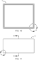
- FIG. 30 shows various elevation views of the sleeve 108 .
- FIG. 31 A shows various elevation views of one of the wedges 110 .
- FIG. 31 B shows a close-up side view of the thicker end of the wedge 110 .
- FIG. 32 is a close-up side view of a side portion of the thinner end of wedge 110 .
- composition refers to any one of the embodiments of the disclosure described herein, and any equivalents.
- reference to various feature(s) of the “composition,” “device,” “structure,” “method,” “disclosure,” “present composition,” “present device,” “present apparatus,” “present method,” or “present disclosure” throughout this document does not mean that all claimed embodiments or methods must include the reference feature(s).
- relative terms such as “inner,” “outer,” “upper,” “top,” “above,” “lower,” “bottom,” “beneath,” “below,” and similar terms, may be used herein to describe a relationship of one element to another.
- Terms such as “higher,” “lower,” “wider,” “narrower,” and similar terms, may be used herein to describe angular relationships. It is understood that these terms are intended to encompass different orientations of the elements or system in addition to the orientation depicted in the figures.
- first, second, third, etc. may be used herein to describe various elements, components, regions, and/or sections, these elements, components, regions, and/or sections should not be limited by these terms. These terms are only used to distinguish one element, component, region, or section from another. Thus, unless expressly stated otherwise, a first element, component, region, or section discussed below could be termed a second element, component, region, or section without departing from the teachings of the present disclosure. As used herein, the term “and/or” includes any and all combinations of one or more of the associated list items.
- Embodiments as described in the present disclosure can be described herein with reference to view illustrations that are schematic in nature. As such, the actual thickness of elements can be different, and variations from the shapes of the illustrations as a result, for example, of manufacturing techniques and/or tolerances are expected. Thus, the elements illustrated in the figures are schematic in nature and their shapes are not intended to illustrate the precise shape of a region and are not intended to limit the scope of the disclosure.
- Embodiments of the present disclosure include containers designed to contain and/or mitigate high energy events such as blasts from explosions or thermal runaways.
- the containers include a body that is built to define an interior chamber that is shaped to receive an explosive device such as a pipe bomb or another kind of improvised explosive device (IED) or an electronic device susceptible to thermal runaway, such as a device with lithium-ion (LI) batteries, for example.
- the container comprises a plurality of substructures that are arranged in a layered sequence to provide the desired effect.
- the substructures act in concert to decouple the shock load to the main containment structure using shock decoupling with energy dissipation and attenuation technology, having a highly deformable polymer structure, and managed venting.
- thermally dominated events such as a runaway LI battery fire, a crushable medium present in one or more layers of the container presents a significant thermal barrier and contains the fire.
- a compact containment system 10 is used to mitigate the high energy event (e.g., an explosion, a thermal runaway, etc.).
- FIG. 1 shows a side view of the containment system 10 .
- FIG. 2 shows an end view of the containment system 10 .
- the size of the containment system may be dictated by the intended application.
- the containment system 10 may be sized such that it is well-suited for use in a common carrier, such as an airliner, for example.
- This disclosure describes the containment system 10 in detail, but it will be understood by those of skill in the art, that the principles that dictate the performance of the containment system 10 apply to containment systems of other sizes that are designed for different applications.
- FIG. 3 shows a cross-sectional view of the containment system 10 along section line B-B.
- This particular embodiment comprises a container 100 with several layers of material arranged in an ordered sequence starting from the innermost layer and progressing outwards to the exterior.
- the innermost layer is termed as the first layer with the ordinal-termed layers ascending as the layers get farther away from the interior.
- the first layer 101 comprises an aluminum foam having a suitable density, such as approximately 0.5 g/cm 3 , for example.
- This layer 102 may be formed using a pressed powder/foaming agent method and is foamed to shape in a mold tool heated in a furnace.
- suitable materials which mitigate shock transmission, have suitable density, and dissipate energy via non-recoverable work may also be used. Some such materials are, for example, foam titanium, foam copper, or closed-cell polymer foams.
- the second layer 102 comprises pressed inert powder.
- This layer should have a very high thermal breakdown temperature and is designed to break down into smaller particles to dose a fireball and should also have a different density from the first layer 101 .
- the second layer 102 Upon impact of a fireball, the second layer 102 initially compacts irrecoverably and then shatters into micron-sized particulate which will operate to remove energy in the form of heat from the fireball and store it in a solid medium (the second layer 102 ) that is not going to exert as much load onto the container 100 as would a heated fluid, i.e., the gas inside the container 100 .
- the micron-sized particulate will then become entrained in the fireball which works to remove heat energy from the fireball and reduce pressure on the container 100 .
- suitable materials for the second layer 102 should mitigate shock and hold heat from a fireball in a solid state.
- One suitable material for this layer 102 is SiO 2 with glass wool fibers added therein.
- Some other exemplary suitable materials for the second layer 102 are: aerogels; cement-based fiber board; drywall; pressed alkali metal compounds (e.g., calcium carbonate, sodium bicarbonate, sodium carbonate); closed-cell polyurethane foam; pumice; vermiculite; perlite; and pressed low-melting-point glass beads. Other materials may also be used.
- the third layer 103 comprises an E-glass, which is alumino-borosilicate glass with less than 1% w/w alkali oxides, mainly used for glass-reinforced plastics.
- the fiber/resin content and thickness of this layer 103 are determined based on the anticipated threat level.
- the third layer 103 distributes the available load across the entire face of the third layer 103 which has the effect of slowing down the response time of the structural components of the container 100 to prevent them from breaking.
- the third layer 103 also has a different density than the first and second layers, 101 , 102 .
- the density differential from layer to layer is intended to increase the time it takes for the system to reach a steady-state equilibrium, allowing the container components more time to react structurally.
- one suitable material for the third layer 103 is an E-glass.
- Other exemplary suitable materials include: aramid fiber composites (e.g., KevlarTM or TwaronTM); carbon fiber; aluminum; titanium; and steel. Other materials are also possible.
- the fourth layer 104 comprises a polyurethane (PU).
- the material selected should have a 300-400% strain-to-failure criteria and a Shore hardness between 50D and 60A. This range allows for different responses depending on anticipated operating temperature range. Deployment in high-temperature environments would require a higher hardness at room temperature to allow for viscosity drop at higher temperatures.
- the thickness of the fourth layer 104 may be determined by anticipated threat level. During a high energy event the fourth layer should be able to expand to a multiple (e.g., 2-3 times) its initial volume. This expansion works to remove energy from the fireball inside the container 100 so that when the fireball is released from the containment system 10 minimal damage occurs to outside structures.
- one suitable material for the fourth layer 104 is polyurethane.
- Other exemplary suitable materials include: aramid fiber composites (e.g., KevlarTM and TwaronTM); polyethylene fiber composites (e.g., DyneemaTM or SpectraTM); pressed polyethylene; and polybenzoisooxazole fiber composites (e.g., ZylonTM). Other materials may also be used.
- the top of the container 100 is open to provide access to the interior chamber and allow for the placement of an explosive device (ED) therein when the container 100 is in an unassembled state.
- ED explosive device
- the opening can be covered with a lid 106 which may comprise at least one of the layers that compose the other sides of the container 100 .
- the lid 106 comprises a series of layers 111 , 112 , 113 , 114 which correspond with the layers 101 , 102 , 103 , 104 of the container 100 to create a series of enclosures of the same material.
- FIG. 5 is an exploded view of the container 100 and the lid 106 .
- the container comprises the layers 101 , 102 , 103 , 104 arranged in a nested configuration.
- the lid 106 comprises the corresponding lid layers 111 , 112 , 113 , 114 .
- FIG. 6 is a close-up of a corner portion of the container 100 .
- the lid layers 111 , 112 , 113 , 114 are sized such that the lid can fit snugly onto the container as best shown in FIGS. 5 and 6 .
- the top surfaces of the first and second container layers 101 , 102 are flush such that when the lid 106 and the container 100 are assembled, the lid layer 111 sits within the perimeter of the first layer 101 with the lid layer 112 sitting atop the first and second layers 101 , 102 .
- the top surfaces of the third and fourth container layers 103 , 104 are flush such that when the lid 106 and the container 100 are assembled, the lid layer 113 sits within the perimeter of the third layer 103 with the lid layer 114 sitting atop the third and fourth layers 103 , 104 .
- a gasket 116 is included in a dugout groove 118 in the top surface of the fourth layer 104 as best shown in FIGS. 6 and 16 .
- the groove 118 is sized to receive the gasket 116 such that when the lid 106 is placed on the container 100 , the gasket 116 is compressed and substantially fills the groove 118 to provide a seal that prevents hot gas and particulate from escaping the container 100 during a high energy event.
- FIG. 7 is an exploded view an embodiment of the system in a disassembled state.
- FIG. 8 shows the system in an assembled state, ready for use.
- the lid 106 may be fastened to the container 100 using various mechanical fasteners, or it can be press-fit onto the container and held together with an external structure such as a fabric sleeve.
- the container 100 and the lid 106 can be inserted into a sleeve 108 (as shown in FIGS. 7 and 8 ).
- the source can be placed in the container 100 which can be secured within the sleeve 108 using two opposing wedges 110 that may be slid between the lid and the sleeve as discussed in more detail herein.
- the container 100 may be quickly inserted into the sleeve 108 by a user and then secured by inserting the wedges 110 between the top surface of the container 100 and the sleeve 108 from opposite ends.
- the wedges 110 will initially resist and then will be crushed into a powder and dissipated, taking kinetic energy away from the container 100 so that the load is applied more slowly to the sleeve 108 .
- FIG. 4 is a close-up view of a portion of the container 100 showing the wedges 110 .
- the wedges 110 may be ridged as shown to prevent back-out during a high energy event. However, in other embodiments the ridges will be unnecessary as the wedges 110 will bend upward during a high energy event and the deformation itself will prevent back-out.
- One suitable material for the wedges 110 is a stiff polymer foam, e.g., a closed-cell polyurethane elastomer.
- Other suitable materials include, for example, aluminum or carbon fiber.
- Suitable materials for the sleeve 108 include, for example, Kevlar®, Dyneema®, and woven aluminum.
- the allowable strain of the sleeve 108 determines the rate at which the container vents during a high energy event.
- FIG. 9 is an elevation view of end of another embodiment of a containment system 20 .
- a bladder 112 that may be rapidly filled with an inert gas such as CO 2 may be placed between the lid 106 and the sleeve, so that when the bladder 112 is inflated the lid 106 is pressed snuggly against the container 100 .
- Other mechanisms may also be used to seal the lid 106 over the container 100 .
- FIG. 10 is a top plan view of the container 100 .
- FIG. 11 is a side elevation view of the container 100 .
- FIG. 12 is a close-up view of a side corner portion of the container 100 .
- FIG. 13 is a close-up view of a top corner portion of the container 100 .
- FIG. 14 is an elevation view of an end portion of fourth layer 104 of the container 100 .
- FIG. 15 is a sectional view of the fourth layer 104 of the container 100 taken along section line G-G.
- FIG. 16 is a close-up view of a corner portion of the fourth layer 104 including the uncompressed gasket 116 which is seated in the groove 118 .
- FIG. 17 A shows various views of the lid 106 .
- FIG. 17 B shows a cross-sectional view of the lid 106 along section line 17 B- 17 B from FIG. 17 A .
- FIG. 18 shows various views of the bottom portion of the third layer 103 of the container 100 .
- FIG. 19 shows various views of the lid layer 113 .
- FIG. 20 shows various views of a side portion of the third layer 103 along the long side of the rectangular container 100 .
- FIG. 21 shows various views of an end portion of the third layer 103 along the short side of the rectangular container 100 .
- FIG. 22 shows various views of the bottom portion of the second layer 102 .
- FIG. 23 shows various views of a side portion of the second layer 102 along the long side of the rectangular container 100 .
- FIG. 24 shows various views of an end portion of the second layer 102 along the short side of the rectangular container 100 .
- FIG. 25 A shows various views of the lid layer 112 .
- FIG. 25 B shows a close-up view of a corner of the lid layer 112 .
- FIG. 26 shows various views of the bottom portion of the first layer 101 .
- FIG. 27 shows various views of a side portion of the first layer 101 along the long side of the rectangular container 100 .
- FIG. 28 shows various views of an end portion of the first layer 101 along the short side of the rectangular container 100 .
- FIG. 29 A shows various views of the lid layer 111 .
- FIG. 29 B shows a close-up view of a corner of the lid layer 111 .
- FIG. 30 shows various views of the sleeve 108 .
- FIG. 31 A shows various views of one of the wedges 110 .
- FIG. 31 B shows a close-up side view of the thicker end of the wedge 110 .
- FIG. 32 shows a close-up side view of a side portion of the thinner end of wedge 110 .
- an ED may be placed in the container 100 , with the container 100 being subsequently secured.
- an explosive shock propagates and eventually arrives at the interior surface of the first layer 101 of the container 100 .
- the transmitted stress propagates into the first layer 101 which, in this embodiment, comprises a metal foam layer.
- the first layer 101 After transmitting its peak allowable stress onto the second layer 102 , the first layer 101 begins to fail. This mechanism absorbs energy from the accepted wave and uses it to damage the first layer 101 .
- the wave propagating through the material encounters the second layer 102 , and a portion is reflected internally to be trapped successively within the first layer 101 , delaying the arrival of peak stress at the interface and allowing a gradual loading of the successive face.
- the first layer 101 reaches maximum density and begins to transmit load directly onto the second layer 102 .
- the transmitted stress begins initially to transmit into the second layer 102 at peak allowable stress in the first layer 101 .
- This direct stress falls to the failure stress of the first layer 101 almost immediately.
- the applied stress to the second layer 102 during this time period is the failure stress of the first layer 101 , plus successive transmitted waves into it from the first layer 101 .
- these waves transmit through the second layer 102 , they cause densification and eventual crushing, reducing energy subsequently.
- the same reflection/transmission process occurs due to acoustic impedance mismatching, thus trapping the waves, and delaying peak stress in the third layer 103 .
- the second layer 102 experiences release, i.e., each time a wave reflects from the distal face, some of the material will be ejected into the fireball from the explosion. This material is inert and will have a high surface area. This serves to reduce the thermal energy of the fireball, and according to the gas laws, the pressure applied in the container 100 .
- the residual load is applied to the thick fourth layer 104 .
- This layer 104 has a very high strain-to-failure characteristic.
- the third layer 103 serves to delay the expansion of the container 100 further, adding stiffness and reducing the final energy incident on the fourth layer 104 .
- the hot vented gas passes through the sleeve 108 , which, in one embodiment, comprises high-strength fibers dosed with electrospun nano-fibers, cooling the expanding gasses and reducing the pressure to a safer level. Eventually enough gas is vented that the container 100 contracts containing the residue.
- an LI battery experiencing thermal runaway may be placed within the container 100 which is then secured.
- the container 100 rapidly heats and is filled with fumes.
- the fourth layer 114 of the lid 106 acts as a low pressure (e.g., pressure ⁇ 2 bar) seal and contains the toxic fumes. Heat slowly propagates through the first layer 101 and begins heating the second layer 102 . If the heat increases sufficiently, the first layer 101 will melt but will be contained within the second layer 102 . The phase change may occur fairly uniformly across the entire interior surface of the first layer 101 which is a desirable distribution of the thermal energy.
- the second layer 102 heats up but prevents heat from reaching the breakdown temperature of the third and fourth layers 103 , 104 , preventing venting.
- the combination of the first layer 101 and the second layer 102 can form an extremely effective thermal barrier to prevent heat from propagating to the third and fourth layers 103 , 104 .
- the container may simply comprise a foam metal layer, a pressed powder layer, and a heat-resistant outer layer formed from a material such as basalt fibers, for example.
Landscapes
- Engineering & Computer Science (AREA)
- Mechanical Engineering (AREA)
- General Engineering & Computer Science (AREA)
- Packages (AREA)
- Buffer Packaging (AREA)
- Sealing Battery Cases Or Jackets (AREA)
- Battery Mounting, Suspending (AREA)
- Aiming, Guidance, Guns With A Light Source, Armor, Camouflage, And Targets (AREA)
Abstract
Description
Claims (19)
Priority Applications (1)
| Application Number | Priority Date | Filing Date | Title |
|---|---|---|---|
| US17/893,140 US12098022B2 (en) | 2021-08-20 | 2022-08-22 | Devices and methods for blast containment |
Applications Claiming Priority (2)
| Application Number | Priority Date | Filing Date | Title |
|---|---|---|---|
| US202163235646P | 2021-08-20 | 2021-08-20 | |
| US17/893,140 US12098022B2 (en) | 2021-08-20 | 2022-08-22 | Devices and methods for blast containment |
Publications (2)
| Publication Number | Publication Date |
|---|---|
| US20230057445A1 US20230057445A1 (en) | 2023-02-23 |
| US12098022B2 true US12098022B2 (en) | 2024-09-24 |
Family
ID=85228757
Family Applications (1)
| Application Number | Title | Priority Date | Filing Date |
|---|---|---|---|
| US17/893,140 Active 2042-11-25 US12098022B2 (en) | 2021-08-20 | 2022-08-22 | Devices and methods for blast containment |
Country Status (3)
| Country | Link |
|---|---|
| US (1) | US12098022B2 (en) |
| EP (1) | EP4388276A4 (en) |
| WO (1) | WO2023069185A2 (en) |
Cited By (2)
| Publication number | Priority date | Publication date | Assignee | Title |
|---|---|---|---|---|
| US20230358511A1 (en) * | 2022-05-09 | 2023-11-09 | Advanced Blast Protection Systems, LLC, dba SALERIA | Systems and methods for protection against blast and ballistic threats |
| US20250368346A1 (en) * | 2021-02-05 | 2025-12-04 | Archer Aviation Inc. | Battery Storage System for an Aircraft |
Citations (15)
| Publication number | Priority date | Publication date | Assignee | Title |
|---|---|---|---|---|
| US3949928A (en) * | 1975-02-12 | 1976-04-13 | Diamond International Corporation | Carton construction |
| US4741276A (en) * | 1985-10-10 | 1988-05-03 | United Kingdom Atomic Energy Authority | Fire resistant cabinet |
| US6686003B2 (en) * | 1998-11-13 | 2004-02-03 | Fireking International, Inc. | High performance fire-protection containers |
| US6752092B2 (en) * | 2001-07-16 | 2004-06-22 | John D. Brush & Co., Inc. | Fire and water-resistant container |
| US20100270318A1 (en) * | 2009-04-24 | 2010-10-28 | Dagher Habib J | Panel assembly for cargo containers |
| US7916487B2 (en) * | 2005-03-30 | 2011-03-29 | Yosef Bitton | Method and apparatus for the enhanced disaster survivability of a networked computer server |
| US20110089173A1 (en) * | 2009-10-21 | 2011-04-21 | SAI Technologies, Inc. | Biodegradable material and container for fluids |
| US20110174509A1 (en) * | 2010-01-18 | 2011-07-21 | Armacell Enterprise Gmbh | Fire protection system for expanded polymers |
| US20120180707A1 (en) * | 2009-10-28 | 2012-07-19 | Dellorusso Jr Anthony J | Fire resistant containment system having a light weight portable removable enclosure |
| US8887515B2 (en) * | 2012-08-23 | 2014-11-18 | Pelican Biopharma, Llc | Thermal management systems and methods |
| US20160251138A1 (en) * | 2015-02-26 | 2016-09-01 | GNS Gesellschaft für Nuklear-Service mbH | Container for radioactive inventory and method of making same |
| US20180356195A1 (en) * | 2015-12-07 | 2018-12-13 | Dynaenergetics Gmbh & Co. Kg | Shaped charge metal foam package |
| US20190137037A1 (en) * | 2014-08-26 | 2019-05-09 | Carl Gehlhausen | Shipping container having a flame retardant layer and a thermal blocking layer |
| US20220319727A1 (en) * | 2019-09-13 | 2022-10-06 | Limited Liability Company "Ceramic Technologies Ltd". | Container for storing, transporting and disposal of radioactive waste |
| US11873152B2 (en) * | 2019-06-17 | 2024-01-16 | Panasonic Intellectual Property Management Co., Ltd. | Thermostatic container |
Family Cites Families (4)
| Publication number | Priority date | Publication date | Assignee | Title |
|---|---|---|---|---|
| ES2213021T3 (en) * | 1999-03-10 | 2004-08-16 | Fraunhofer-Gesellschaft Zur Forderung Der Angewandten Forschung E.V. | USE OF METAL FOAMS IN SHIELDING SYSTEMS. |
| CN207335550U (en) * | 2017-06-29 | 2018-05-08 | 胡达开 | A kind of ammunition accumulating explosion-proof tank |
| CN108302998B (en) * | 2018-01-16 | 2020-04-07 | 中国工程物理研究院流体物理研究所 | Protective armor structure in explosion container and design method thereof |
| CN108426491B (en) * | 2018-05-15 | 2023-11-28 | 河北金后盾塑胶有限公司 | Flame-retardant explosion-proof ammunition box |
-
2022
- 2022-08-22 EP EP22884225.8A patent/EP4388276A4/en active Pending
- 2022-08-22 US US17/893,140 patent/US12098022B2/en active Active
- 2022-08-22 WO PCT/US2022/041127 patent/WO2023069185A2/en not_active Ceased
Patent Citations (15)
| Publication number | Priority date | Publication date | Assignee | Title |
|---|---|---|---|---|
| US3949928A (en) * | 1975-02-12 | 1976-04-13 | Diamond International Corporation | Carton construction |
| US4741276A (en) * | 1985-10-10 | 1988-05-03 | United Kingdom Atomic Energy Authority | Fire resistant cabinet |
| US6686003B2 (en) * | 1998-11-13 | 2004-02-03 | Fireking International, Inc. | High performance fire-protection containers |
| US6752092B2 (en) * | 2001-07-16 | 2004-06-22 | John D. Brush & Co., Inc. | Fire and water-resistant container |
| US7916487B2 (en) * | 2005-03-30 | 2011-03-29 | Yosef Bitton | Method and apparatus for the enhanced disaster survivability of a networked computer server |
| US20100270318A1 (en) * | 2009-04-24 | 2010-10-28 | Dagher Habib J | Panel assembly for cargo containers |
| US20110089173A1 (en) * | 2009-10-21 | 2011-04-21 | SAI Technologies, Inc. | Biodegradable material and container for fluids |
| US20120180707A1 (en) * | 2009-10-28 | 2012-07-19 | Dellorusso Jr Anthony J | Fire resistant containment system having a light weight portable removable enclosure |
| US20110174509A1 (en) * | 2010-01-18 | 2011-07-21 | Armacell Enterprise Gmbh | Fire protection system for expanded polymers |
| US8887515B2 (en) * | 2012-08-23 | 2014-11-18 | Pelican Biopharma, Llc | Thermal management systems and methods |
| US20190137037A1 (en) * | 2014-08-26 | 2019-05-09 | Carl Gehlhausen | Shipping container having a flame retardant layer and a thermal blocking layer |
| US20160251138A1 (en) * | 2015-02-26 | 2016-09-01 | GNS Gesellschaft für Nuklear-Service mbH | Container for radioactive inventory and method of making same |
| US20180356195A1 (en) * | 2015-12-07 | 2018-12-13 | Dynaenergetics Gmbh & Co. Kg | Shaped charge metal foam package |
| US11873152B2 (en) * | 2019-06-17 | 2024-01-16 | Panasonic Intellectual Property Management Co., Ltd. | Thermostatic container |
| US20220319727A1 (en) * | 2019-09-13 | 2022-10-06 | Limited Liability Company "Ceramic Technologies Ltd". | Container for storing, transporting and disposal of radioactive waste |
Non-Patent Citations (2)
| Title |
|---|
| International Search Report for App. No. PCT/US22/041127, Dated May 10, 23. |
| International Written Opinion for App. No. PCT/US22/041127. |
Cited By (2)
| Publication number | Priority date | Publication date | Assignee | Title |
|---|---|---|---|---|
| US20250368346A1 (en) * | 2021-02-05 | 2025-12-04 | Archer Aviation Inc. | Battery Storage System for an Aircraft |
| US20230358511A1 (en) * | 2022-05-09 | 2023-11-09 | Advanced Blast Protection Systems, LLC, dba SALERIA | Systems and methods for protection against blast and ballistic threats |
Also Published As
| Publication number | Publication date |
|---|---|
| EP4388276A2 (en) | 2024-06-26 |
| EP4388276A4 (en) | 2025-07-23 |
| US20230057445A1 (en) | 2023-02-23 |
| WO2023069185A2 (en) | 2023-04-27 |
| WO2023069185A3 (en) | 2023-07-06 |
Similar Documents
| Publication | Publication Date | Title |
|---|---|---|
| US12098022B2 (en) | Devices and methods for blast containment | |
| US20100307327A1 (en) | Blast effect mitigating assemble using aerogels | |
| US5833782A (en) | High-energy-absorbing enclosure for internal explosion containment | |
| KR102560446B1 (en) | Composite pad capable delaying thermal runaway of battery cell | |
| US7866248B2 (en) | Encapsulated ceramic composite armor | |
| CN103180685B (en) | There is the armour plate of bar shaped protection element and absorb the method for bullet energy | |
| KR20220002557A (en) | train shield | |
| US5225622A (en) | Acoustic/shock wave attenuating assembly | |
| WO1995001484A1 (en) | Acoustic/shock wave attenuating assembly | |
| US6196107B1 (en) | Explosive containment device | |
| EP4364232B1 (en) | Materials, systems, and methods for encapsulating thermal barrier materials | |
| RU2220076C1 (en) | Device for protection of data recorder memory circuits in emergency | |
| US20100257997A1 (en) | Armor Plate | |
| KR20230154431A (en) | Materials, systems and methods for encapsulating thermal barriers | |
| CN111141185A (en) | A multifunctional ammunition packing box | |
| US20090145289A1 (en) | Composite armor plate and method for using the same | |
| US8720722B2 (en) | Venting mechanism for containers | |
| KR20100081325A (en) | Apparatus, methods and system for improved lightweight armor protection | |
| EP0706596A1 (en) | Acoustic/shock wave attenuating assembly | |
| EP4337463A1 (en) | Venting and filtering components for encapsulated thermal barriers | |
| WO2008097375A2 (en) | Encapsulated ceramic composite armor | |
| KR102081050B1 (en) | Fireproof door for ship and ship with the same | |
| KR20230077123A (en) | Composite panel for structural explosion-proof reinforcement and its installation structure | |
| Bowering | Strain rate effects on energy dissipation during hypervelocity penetration of polymeric materials | |
| KR20230104854A (en) | Reactor Core Melt Containment and Cooling System |
Legal Events
| Date | Code | Title | Description |
|---|---|---|---|
| FEPP | Fee payment procedure |
Free format text: ENTITY STATUS SET TO UNDISCOUNTED (ORIGINAL EVENT CODE: BIG.); ENTITY STATUS OF PATENT OWNER: SMALL ENTITY |
|
| FEPP | Fee payment procedure |
Free format text: ENTITY STATUS SET TO SMALL (ORIGINAL EVENT CODE: SMAL); ENTITY STATUS OF PATENT OWNER: SMALL ENTITY |
|
| STPP | Information on status: patent application and granting procedure in general |
Free format text: DOCKETED NEW CASE - READY FOR EXAMINATION |
|
| AS | Assignment |
Owner name: SYNTHETIK APPLIED TECHNOLOGIES LLC, TEXAS Free format text: ASSIGNMENT OF ASSIGNORS INTEREST;ASSIGNOR:ADVANCED BLAST PROTECTION SYSTEMS LLC;REEL/FRAME:064980/0596 Effective date: 20230410 |
|
| STPP | Information on status: patent application and granting procedure in general |
Free format text: NON FINAL ACTION MAILED |
|
| STPP | Information on status: patent application and granting procedure in general |
Free format text: RESPONSE TO NON-FINAL OFFICE ACTION ENTERED AND FORWARDED TO EXAMINER |
|
| STPP | Information on status: patent application and granting procedure in general |
Free format text: NOTICE OF ALLOWANCE MAILED -- APPLICATION RECEIVED IN OFFICE OF PUBLICATIONS |
|
| STPP | Information on status: patent application and granting procedure in general |
Free format text: AWAITING TC RESP., ISSUE FEE NOT PAID |
|
| STPP | Information on status: patent application and granting procedure in general |
Free format text: NOTICE OF ALLOWANCE MAILED -- APPLICATION RECEIVED IN OFFICE OF PUBLICATIONS |
|
| AS | Assignment |
Owner name: SYNTHETIK APPLIED TECHNOLOGIES LLC, TEXAS Free format text: ASSIGNMENT OF ASSIGNORS INTEREST;ASSIGNORS:WARREN, JAMES ARTHUR;BLAYLOCK, JASON LOVAINE;SIGNING DATES FROM 20231130 TO 20240118;REEL/FRAME:068368/0513 |
|
| STCF | Information on status: patent grant |
Free format text: PATENTED CASE |