US12096584B2 - Plug-in holder, plug-in module and electronic device - Google Patents
Plug-in holder, plug-in module and electronic device Download PDFInfo
- Publication number
- US12096584B2 US12096584B2 US17/717,123 US202217717123A US12096584B2 US 12096584 B2 US12096584 B2 US 12096584B2 US 202217717123 A US202217717123 A US 202217717123A US 12096584 B2 US12096584 B2 US 12096584B2
- Authority
- US
- United States
- Prior art keywords
- plug
- frame
- holder
- engaging
- card
- Prior art date
- Legal status (The legal status is an assumption and is not a legal conclusion. Google has not performed a legal analysis and makes no representation as to the accuracy of the status listed.)
- Active, expires
Links
Images




Classifications
-
- H—ELECTRICITY
- H01—ELECTRIC ELEMENTS
- H01R—ELECTRICALLY-CONDUCTIVE CONNECTIONS; STRUCTURAL ASSOCIATIONS OF A PLURALITY OF MUTUALLY-INSULATED ELECTRICAL CONNECTING ELEMENTS; COUPLING DEVICES; CURRENT COLLECTORS
- H01R12/00—Structural associations of a plurality of mutually-insulated electrical connecting elements, specially adapted for printed circuits, e.g. printed circuit boards [PCB], flat or ribbon cables, or like generally planar structures, e.g. terminal strips, terminal blocks; Coupling devices specially adapted for printed circuits, flat or ribbon cables, or like generally planar structures; Terminals specially adapted for contact with, or insertion into, printed circuits, flat or ribbon cables, or like generally planar structures
- H01R12/70—Coupling devices
- H01R12/71—Coupling devices for rigid printing circuits or like structures
- H01R12/72—Coupling devices for rigid printing circuits or like structures coupling with the edge of the rigid printed circuits or like structures
- H01R12/73—Coupling devices for rigid printing circuits or like structures coupling with the edge of the rigid printed circuits or like structures connecting to other rigid printed circuits or like structures
- H01R12/735—Printed circuits including an angle between each other
- H01R12/737—Printed circuits being substantially perpendicular to each other
-
- H—ELECTRICITY
- H05—ELECTRIC TECHNIQUES NOT OTHERWISE PROVIDED FOR
- H05K—PRINTED CIRCUITS; CASINGS OR CONSTRUCTIONAL DETAILS OF ELECTRIC APPARATUS; MANUFACTURE OF ASSEMBLAGES OF ELECTRICAL COMPONENTS
- H05K7/00—Constructional details common to different types of electric apparatus
- H05K7/14—Mounting supporting structure in casing or on frame or rack
- H05K7/1417—Mounting supporting structure in casing or on frame or rack having securing means for mounting boards, plates or wiring boards
-
- G—PHYSICS
- G06—COMPUTING OR CALCULATING; COUNTING
- G06F—ELECTRIC DIGITAL DATA PROCESSING
- G06F1/00—Details not covered by groups G06F3/00 - G06F13/00 and G06F21/00
- G06F1/16—Constructional details or arrangements
- G06F1/18—Packaging or power distribution
- G06F1/183—Internal mounting support structures, e.g. for supporting printed circuit boards
- G06F1/185—Mounting of expansion boards
-
- H—ELECTRICITY
- H05—ELECTRIC TECHNIQUES NOT OTHERWISE PROVIDED FOR
- H05K—PRINTED CIRCUITS; CASINGS OR CONSTRUCTIONAL DETAILS OF ELECTRIC APPARATUS; MANUFACTURE OF ASSEMBLAGES OF ELECTRICAL COMPONENTS
- H05K7/00—Constructional details common to different types of electric apparatus
- H05K7/02—Arrangements of circuit components or wiring on supporting structure
- H05K7/12—Resilient or clamping means for holding component to structure
Definitions
- the disclosure relates to a plug-in holder and, more particularly, to a plug-in holder for installing a plug-in card on a circuit board and a plug-in module and an electronic device equipped with the plug-in holder.
- the disclosure provides a plug-in holder for installing a plug-in card into a circuit board and a plug-in module and an electronic device equipped with the plug-in holder, so as to solve the aforesaid problems.
- a plug-in module comprises a circuit board and a plug-in holder.
- the circuit board has at least one engaging hole.
- the plug-in holder comprises a frame, a first engaging structure and at least one second engaging structure.
- the frame has a first side and a second side, wherein the first side is opposite to the second side.
- the first engaging structure is located at the first side.
- the at least one second engaging structure is located at the second side.
- the plug-in holder is installed on the circuit board and the at least one second engaging structure engages with the at least one engaging hole.
- an electronic device comprises a casing, a circuit board, a plug-in card and a plug-in holder.
- the circuit board is disposed in the casing and the circuit board has at least one engaging hole.
- the plug-in card has an engaging recess.
- the plug-in holder comprises a frame, a first engaging structure and at least one second engaging structure.
- the frame has a first side and a second side, wherein the first side is opposite to the second side.
- the first engaging structure is located at the first side.
- the at least one second engaging structure is located at the second side.
- the plug-in card is disposed on the frame and the first engaging structure engages with the engaging recess.
- the plug-in holder installs the plug-in card on the circuit board and the at least one second engaging structure engages with the at least one engaging hole.
- a plug-in holder comprises a frame, a first engaging structure and at least one second engaging structure.
- the frame has a first side and a second side, wherein the first side is opposite to the second side.
- the first engaging structure is located at the first side.
- the at least one second engaging structure is located at the second side.
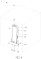
- FIG. 1 is a schematic view illustrating an electronic device according to an embodiment of the disclosure.
- FIG. 2 is a perspective view illustrating a circuit board, a plug-in card and a plug-in holder shown in FIG. 1 from another viewing angle.
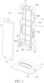
- FIG. 3 is an exploded view illustrating the circuit board, the plug-in card and the plug-in holder shown in FIG. 1 .
- FIG. 4 is a perspective view illustrating the plug-in holder shown in FIG. 3 from another viewing angle.
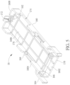
- FIG. 5 is a perspective view illustrating the plug-in holder shown in FIG. 3 from another viewing angle.
- FIG. 6 is a perspective view illustrating the plug-in card shown in FIG. 3 being disposed on a frame of the plug-in holder.
- FIG. 1 is a schematic view illustrating an electronic device 1 according to an embodiment of the disclosure
- FIG. 2 is a perspective view illustrating a circuit board 12 , a plug-in card 14 and a plug-in holder 16 shown in FIG. 1 from another viewing angle
- FIG. 3 is an exploded view illustrating the circuit board 12 , the plug-in card 14 and the plug-in holder 16 shown in FIG. 1
- FIG. 4 is a perspective view illustrating the plug-in holder 16 shown in FIG. 3 from another viewing angle
- FIG. 5 is a perspective view illustrating the plug-in holder 16 shown in FIG. 3 from another viewing angle
- FIG. 6 is a perspective view illustrating the plug-in card 14 shown in FIG. 3 being disposed on a frame 160 of the plug-in holder 16 .
- an electronic device 1 comprises a casing 10 , a circuit board 12 , a plug-in card 14 and a plug-in holder 16 .
- a plug-in module of the disclosure may essentially consist of the circuit board 12 and the plug-in holder 16 .
- the electronic device 1 may be a computer, a server, or other electronic devices equipped with the circuit board 12 , the plug-in card 14 and the plug-in holder 16 according to practical applications.
- the electronic device 1 may be further equipped with some necessary hardware and/or software components for specific purposes, such as processor, memory, power supply, applications, communication module, etc., and it depends on practical applications.
- the casing 10 shown in FIG. 1 is illustrated by dotted line and the appearance of the casing 10 may be designed according to practical applications.
- the circuit board 12 is disposed in the casing 10 and the circuit board 12 has at least one engaging hole 120 and a first electrical connector 122 .
- the circuit board 12 may have two engaging holes 120 and the first electrical connector 122 is located between the two engaging holes 120 .
- the first electrical connector 122 may be a slot connector and an opening of the first electrical connector 122 is orientated in a direction perpendicular to the circuit board 12 . It should be noted that the size of the circuit board 12 may be determined according to practical applications, so the disclosure is not limited to the embodiment shown in the figures.
- the plug-in card 14 has an engaging recess 140 and a second electrical connector 142 , wherein the second electrical connector 142 and the engaging recess 140 are located at opposite ends of the plug-in card 14 .
- the second electrical connector 142 may be a card edge connector.
- the second electrical connector 142 of the plug-in card 14 may be vertically inserted into the first electrical connector 122 of the circuit board 12 , such that the second electrical connector 142 is electrically connected to the first electrical connector 122 .
- the plug-in card 14 may be, but not limited to, an M.2 module card. In another embodiment, the plug-in card 14 may also be other module cards capable of being installed on the circuit board 12 .
- the plug-in holder 16 is used to install the plug-in card 14 on the circuit board 12 .
- the plug-in holder 16 may install the plug-in card 14 vertically on the circuit board 12 , but the disclosure is not so limited.
- the plug-in holder 16 comprises a frame 160 , a first engaging structure 162 , at least one second engaging structure 164 , at least one retaining structure 166 , at least one clamping structure 168 , a support structure 170 , an extending structure 172 , at least one recess structure 174 and a reinforcing structure 176 .
- the frame 160 has a first side 1600 and a second side 1602 , wherein the first side 1600 is opposite to the second side 1602 .
- the first engaging structure 162 is located at the first side 1600 of the frame 160 and the extending structure 172 extends from the first engaging structure 162 in a direction away from the frame 160 .
- the first engaging structure 162 may be an elastic hook extending from the first side 1600 of the frame 160 .
- a user may pull the extending structure 172 outward to make the first engaging structure 162 deform elastically.
- the at least one second engaging structure 164 and the at least one retaining structure 166 are located at the second side 1602 of the frame 160 .
- the second side 1602 of the frame 160 may have at least one side wall 1604 , wherein the at least one second engaging structure 164 is located at an outside of the at least one side wall 1604 , and the at least one retaining structure 166 is located at an inside of the at least one side wall 1604 .
- the plug-in holder 16 may comprise two second engaging structures 164 and two retaining structures 166 , and the second side 1602 of the frame 160 may have two side walls 1604 , wherein the two second engaging structures 164 and the two retaining structures 166 are located at opposite sides of the second side 1602 of the frame 160 respectively, the two second engaging structures 164 are located at the outside of the two side walls 1604 , and the two retaining structures 166 are located at the inside of the two side walls 1604 .
- the second engaging structure 164 may be an elastic hook extending from the outside of the side wall 1604
- the retaining structure 166 may be a retaining wall extending from the inside of the side wall 1604 . The user may press the second engaging structure 164 to make the second engaging structure 164 deform elastically.
- the support structure 170 is located at the second side 1602 of the frame 160 .
- the support structure 170 may be a U-shaped structure on the bottom of the second side 1602 of the frame 160 .
- the support structure 170 may also be strip-shaped, L-shaped or other shapes according to practical applications.
- the at least one clamping structure 168 and the at least one recess structure 174 are located at at least one side of the frame 160 .
- the plug-in holder 16 may comprise two clamping structures 168 and two recess structures 174 , wherein the two clamping structures 168 and the two recess structures 174 are located at opposite sides of the frame 160 respectively.
- the clamping structure 168 may an elastic protrusion.
- the reinforcing structure 176 is located at an inner surface 1606 of the frame 160 .
- the reinforcing structure 176 may essentially consist of a plurality of ribs intersecting with each other, but the disclosure is not so limited.
- the reinforcing structure 176 is used to reinforce the overall strength of the plug-in holder 16 .
- the type and arrangement of the reinforcing structure 176 may be determined according to practical applications, so the disclosure is not limited to the embodiment shown in the figures.
- the user may dispose the plug-in card 14 on the frame 160 of the plug-in holder 16 first, as shown in FIG. 6 .
- the first engaging structure 162 engages with the engaging recess 140 on one end of the plug-in card 14
- the other end of the plug-in card 14 abuts against the two retaining structures 166
- the two clamping structures 168 clamp opposite sides of the plug-in card 14 .
- the plug-in card 14 is restrained on the frame 160 of the plug-in holder 16 .
- opposite sides of the plug-in card 14 are partially exposed within the two recess structures 174 , and the back of the plug-in card 14 abuts against the reinforcing structure 176 .
- the user may insert the two second engaging structures 164 of the plug-in holder 16 into the two engaging holes 120 of the circuit board 12 and insert the second electrical connector 142 of the plug-in card 14 into the first electrical connector 122 of the circuit board 12 , such that the two second engaging structures 164 engage with the two engaging holes 120 and the second electrical connector 142 is electrically connected to the first electrical connector 122 .
- the support structure 170 of the plug-in holder 16 abuts against the circuit board 12 , such that the plug-in holder 16 stably stands on the circuit board 12 . Accordingly, the plug-in holder 16 can install the plug-in card 14 vertically on the circuit board 12 .
- the plug-in card 14 Since the plug-in card 14 is installed vertically on the circuit board 12 , the second electrical connector 142 of the plug-in card 14 is connected to the first electrical connector 122 in a direction perpendicular to the circuit board 12 . It should be noted that the plug-in holder 16 may also install the plug-in card 14 horizontally on the circuit board 12 according to practical applications.
- the user may press the two second engaging structures 164 to make the two second engaging structures 164 deform elastically. Then, the user may pull the plug-in holder 16 upward, such that the second electrical connector 142 of the plug-in card 14 is separated from the first electrical connector 122 of the circuit board 12 . Then, the user may use two fingers of one hand to grab opposite sides of the plug-in card 14 through the two recess structures 174 and use one finger of the other hand to pull the extending structure 172 outward, so as to disengage the first engaging structure 162 from the engaging recess 140 of the plug-in card 14 . Then, the user may detach the plug-in card 14 from the plug-in holder 16 .
- a user may dispose the plug-in card (e.g. M.2 module card) on the frame of the plug-in holder and then utilize the plug-in holder to install the plug-in card on the circuit board.
- the plug-in card e.g. M.2 module card
- the first engaging structure engages with the plug-in card to restrain the plug-in card on the frame.
- the plug-in holder installs the plug-in card on the circuit board
- the second engaging structure of the frame engages with the circuit board, such that the plug-in holder stably holds the plug-in card on the circuit board.
- the plug-in card may be vertically installed on the circuit board by the plug-in holder. Accordingly, the disclosure can effectively reduce the area of the circuit board occupied by the plug-in card, such that it is beneficial for layout of the circuit board and arrangement of electronic components.
Landscapes
- Engineering & Computer Science (AREA)
- Theoretical Computer Science (AREA)
- Microelectronics & Electronic Packaging (AREA)
- Computer Hardware Design (AREA)
- Power Engineering (AREA)
- Human Computer Interaction (AREA)
- Physics & Mathematics (AREA)
- General Engineering & Computer Science (AREA)
- General Physics & Mathematics (AREA)
- Mounting Of Printed Circuit Boards And The Like (AREA)
Abstract
Description
Claims (17)
Applications Claiming Priority (2)
| Application Number | Priority Date | Filing Date | Title |
|---|---|---|---|
| TW110215178 | 2021-12-21 | ||
| TW110215178U TWM626051U (en) | 2021-12-21 | 2021-12-21 | Plug-in holder, plug-in module and electronic device |
Publications (2)
| Publication Number | Publication Date |
|---|---|
| US20230199995A1 US20230199995A1 (en) | 2023-06-22 |
| US12096584B2 true US12096584B2 (en) | 2024-09-17 |
Family
ID=82063286
Family Applications (1)
| Application Number | Title | Priority Date | Filing Date |
|---|---|---|---|
| US17/717,123 Active 2042-04-14 US12096584B2 (en) | 2021-12-21 | 2022-04-10 | Plug-in holder, plug-in module and electronic device |
Country Status (3)
| Country | Link |
|---|---|
| US (1) | US12096584B2 (en) |
| CN (1) | CN216818676U (en) |
| TW (1) | TWM626051U (en) |
Families Citing this family (1)
| Publication number | Priority date | Publication date | Assignee | Title |
|---|---|---|---|---|
| DE102021116133A1 (en) * | 2021-06-22 | 2022-12-22 | Vacon Oy | heatsink cooling arrangement |
Citations (3)
| Publication number | Priority date | Publication date | Assignee | Title |
|---|---|---|---|---|
| US5329424A (en) * | 1993-09-01 | 1994-07-12 | At&T Bell Laboratories | Busbar holder for securing busbars to a PCB |
| US20220272858A1 (en) * | 2021-02-25 | 2022-08-25 | Dell Products L.P. | Assembly for Card Expansion on Printer Circuit Board |
| US20220374057A1 (en) * | 2021-05-24 | 2022-11-24 | Inventec (Pudong) Technology Corporation | M.2 interface module and server including the same |
-
2021
- 2021-12-21 TW TW110215178U patent/TWM626051U/en unknown
-
2022
- 2022-01-07 CN CN202220038533.9U patent/CN216818676U/en active Active
- 2022-04-10 US US17/717,123 patent/US12096584B2/en active Active
Patent Citations (3)
| Publication number | Priority date | Publication date | Assignee | Title |
|---|---|---|---|---|
| US5329424A (en) * | 1993-09-01 | 1994-07-12 | At&T Bell Laboratories | Busbar holder for securing busbars to a PCB |
| US20220272858A1 (en) * | 2021-02-25 | 2022-08-25 | Dell Products L.P. | Assembly for Card Expansion on Printer Circuit Board |
| US20220374057A1 (en) * | 2021-05-24 | 2022-11-24 | Inventec (Pudong) Technology Corporation | M.2 interface module and server including the same |
Also Published As
| Publication number | Publication date |
|---|---|
| CN216818676U (en) | 2022-06-24 |
| US20230199995A1 (en) | 2023-06-22 |
| TWM626051U (en) | 2022-04-21 |
Similar Documents
| Publication | Publication Date | Title |
|---|---|---|
| US7742291B2 (en) | Computer enclosure adapted for mounting different types of transfer cards | |
| US7826230B2 (en) | Server enclosure with transfer card module | |
| US8208261B2 (en) | Electronic device with power supply | |
| CN204257864U (en) | Interface card stuck-module | |
| US8248770B2 (en) | Mounting apparatus for expansion card | |
| US6358079B1 (en) | Printed circuit card retention mechanism | |
| US20090067142A1 (en) | Retaining mechanism for circuit card | |
| US20110294309A1 (en) | Expansion card and expansion apparatus thereof | |
| US6693800B1 (en) | Expansion card mounting apparatus | |
| US6185093B1 (en) | Expansion card carrier and method for a computer system | |
| US20150009617A1 (en) | Expansion card module | |
| US7200002B2 (en) | Connection port module | |
| US6361343B1 (en) | Circuit card retention mechanism | |
| US11507150B2 (en) | Interface card cage and server | |
| US8411461B2 (en) | Mounting apparatus for expansion cards | |
| CN102346517A (en) | Device for fixing expansion card | |
| US7813136B2 (en) | Server enclosure | |
| US20230199995A1 (en) | Plug-in holder, plug-in module and electronic device | |
| US8480328B2 (en) | Fixing device for expansion cards | |
| CN102221857A (en) | Main machine box with expansion card fixing structure | |
| US7626826B2 (en) | Expansion card carrier and method for assembling the same | |
| CN210466291U (en) | Dustproof effectual computer motherboard that takes precautions against earthquakes | |
| US20170153675A1 (en) | Fastening device | |
| US7721970B2 (en) | Mounting apparatus for card reader | |
| CN101201664B (en) | adapter card holder |
Legal Events
| Date | Code | Title | Description |
|---|---|---|---|
| AS | Assignment |
Owner name: WISTRON CORPORATION, TAIWAN Free format text: ASSIGNMENT OF ASSIGNORS INTEREST;ASSIGNOR:LIN, CHIH-SHEN;REEL/FRAME:059553/0371 Effective date: 20220302 |
|
| FEPP | Fee payment procedure |
Free format text: ENTITY STATUS SET TO UNDISCOUNTED (ORIGINAL EVENT CODE: BIG.); ENTITY STATUS OF PATENT OWNER: LARGE ENTITY |
|
| STPP | Information on status: patent application and granting procedure in general |
Free format text: RESPONSE TO NON-FINAL OFFICE ACTION ENTERED AND FORWARDED TO EXAMINER |
|
| STPP | Information on status: patent application and granting procedure in general |
Free format text: FINAL REJECTION MAILED |
|
| STPP | Information on status: patent application and granting procedure in general |
Free format text: RESPONSE AFTER FINAL ACTION FORWARDED TO EXAMINER |
|
| STPP | Information on status: patent application and granting procedure in general |
Free format text: ADVISORY ACTION MAILED |
|
| STPP | Information on status: patent application and granting procedure in general |
Free format text: DOCKETED NEW CASE - READY FOR EXAMINATION |
|
| STPP | Information on status: patent application and granting procedure in general |
Free format text: NON FINAL ACTION MAILED |
|
| STPP | Information on status: patent application and granting procedure in general |
Free format text: RESPONSE TO NON-FINAL OFFICE ACTION ENTERED AND FORWARDED TO EXAMINER |
|
| STPP | Information on status: patent application and granting procedure in general |
Free format text: NOTICE OF ALLOWANCE MAILED -- APPLICATION RECEIVED IN OFFICE OF PUBLICATIONS |
|
| STPP | Information on status: patent application and granting procedure in general |
Free format text: PUBLICATIONS -- ISSUE FEE PAYMENT RECEIVED |
|
| STCF | Information on status: patent grant |
Free format text: PATENTED CASE |