US12096579B2 - Base station for mounting on ceiling - Google Patents
Base station for mounting on ceiling Download PDFInfo
- Publication number
- US12096579B2 US12096579B2 US17/940,156 US202217940156A US12096579B2 US 12096579 B2 US12096579 B2 US 12096579B2 US 202217940156 A US202217940156 A US 202217940156A US 12096579 B2 US12096579 B2 US 12096579B2
- Authority
- US
- United States
- Prior art keywords
- plate
- base station
- rotating
- shielding
- station according
- Prior art date
- Legal status (The legal status is an assumption and is not a legal conclusion. Google has not performed a legal analysis and makes no representation as to the accuracy of the status listed.)
- Active, expires
Links
Images


Classifications
-
- H—ELECTRICITY
- H01—ELECTRIC ELEMENTS
- H01R—ELECTRICALLY-CONDUCTIVE CONNECTIONS; STRUCTURAL ASSOCIATIONS OF A PLURALITY OF MUTUALLY-INSULATED ELECTRICAL CONNECTING ELEMENTS; COUPLING DEVICES; CURRENT COLLECTORS
- H01R13/00—Details of coupling devices of the kinds covered by groups H01R12/70 or H01R24/00 - H01R33/00
- H01R13/46—Bases; Cases
- H01R13/52—Dustproof, splashproof, drip-proof, waterproof, or flameproof cases
-
- H—ELECTRICITY
- H05—ELECTRIC TECHNIQUES NOT OTHERWISE PROVIDED FOR
- H05K—PRINTED CIRCUITS; CASINGS OR CONSTRUCTIONAL DETAILS OF ELECTRIC APPARATUS; MANUFACTURE OF ASSEMBLAGES OF ELECTRICAL COMPONENTS
- H05K5/00—Casings, cabinets or drawers for electric apparatus
- H05K5/02—Details
- H05K5/03—Covers
-
- H—ELECTRICITY
- H01—ELECTRIC ELEMENTS
- H01R—ELECTRICALLY-CONDUCTIVE CONNECTIONS; STRUCTURAL ASSOCIATIONS OF A PLURALITY OF MUTUALLY-INSULATED ELECTRICAL CONNECTING ELEMENTS; COUPLING DEVICES; CURRENT COLLECTORS
- H01R13/00—Details of coupling devices of the kinds covered by groups H01R12/70 or H01R24/00 - H01R33/00
- H01R13/46—Bases; Cases
- H01R13/502—Bases; Cases composed of different pieces
-
- H—ELECTRICITY
- H01—ELECTRIC ELEMENTS
- H01R—ELECTRICALLY-CONDUCTIVE CONNECTIONS; STRUCTURAL ASSOCIATIONS OF A PLURALITY OF MUTUALLY-INSULATED ELECTRICAL CONNECTING ELEMENTS; COUPLING DEVICES; CURRENT COLLECTORS
- H01R13/00—Details of coupling devices of the kinds covered by groups H01R12/70 or H01R24/00 - H01R33/00
- H01R13/46—Bases; Cases
- H01R13/516—Means for holding or embracing insulating body, e.g. casing, hoods
-
- H—ELECTRICITY
- H01—ELECTRIC ELEMENTS
- H01R—ELECTRICALLY-CONDUCTIVE CONNECTIONS; STRUCTURAL ASSOCIATIONS OF A PLURALITY OF MUTUALLY-INSULATED ELECTRICAL CONNECTING ELEMENTS; COUPLING DEVICES; CURRENT COLLECTORS
- H01R13/00—Details of coupling devices of the kinds covered by groups H01R12/70 or H01R24/00 - H01R33/00
- H01R13/72—Means for accommodating flexible lead within the holder
-
- H—ELECTRICITY
- H05—ELECTRIC TECHNIQUES NOT OTHERWISE PROVIDED FOR
- H05K—PRINTED CIRCUITS; CASINGS OR CONSTRUCTIONAL DETAILS OF ELECTRIC APPARATUS; MANUFACTURE OF ASSEMBLAGES OF ELECTRICAL COMPONENTS
- H05K5/00—Casings, cabinets or drawers for electric apparatus
- H05K5/02—Details
- H05K5/0247—Electrical details of casings, e.g. terminals, passages for cables or wiring
-
- H—ELECTRICITY
- H02—GENERATION; CONVERSION OR DISTRIBUTION OF ELECTRIC POWER
- H02G—INSTALLATION OF ELECTRIC CABLES OR LINES, OR OF COMBINED OPTICAL AND ELECTRIC CABLES OR LINES
- H02G3/00—Installations of electric cables or lines or protective tubing therefor in or on buildings, equivalent structures or vehicles
- H02G3/02—Details
- H02G3/08—Distribution boxes; Connection or junction boxes
- H02G3/10—Distribution boxes; Connection or junction boxes for surface mounting on a wall
-
- H—ELECTRICITY
- H04—ELECTRIC COMMUNICATION TECHNIQUE
- H04W—WIRELESS COMMUNICATION NETWORKS
- H04W88/00—Devices specially adapted for wireless communication networks, e.g. terminals, base stations or access point devices
- H04W88/08—Access point devices
Definitions
- the subject matter herein generally relates to base stations, and more particularly, to a base station for mounting on ceiling.
- Base stations are interface devices for allowing mobile devices to access the Internet.
- the base stations may have a ceiling-mounted configuration.
- Such a base station receives power or signals from a cable (such as a power line or a network cable), the cable connecting with the base station is inserted into a hole defined on the ceiling.
- the cable when the cable has a certain length, the cable may be partially exposed outside the base station after being connected to the base station.
- the exposed cable affects the appearance, and dust may accumulate thereon. Furthermore, damages may happen to the exposed cable. Therefore, there is room for improvement in the art.
- FIG. 1 is a diagrammatic view of a base station according to an embodiment of the present disclosure.
- FIG. 2 is an exploded view of the base station of FIG. 1 .
- FIG. 3 is a diagrammatic view of a shielding assembly of the base station of FIG. 1 .
- FIG. 4 is an exploded view of the shielding assembly of FIG. 3 .
- FIG. 5 is similar to FIG. 4 , but showing the shielding assembly from another angle.
- FIG. 6 is a cross-sectional view along VI-VI of FIG. 3 .
- FIG. 7 is a cross-sectional view along VII-VII of FIG. 1 .
- FIG. 8 is similar to FIG. 2 , but showing the base station from another angle.
- FIG. 9 is a diagrammatic view of a base station according to another embodiment of the present disclosure.
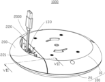
- FIG. 10 is a diagrammatic view of a mounting base of the base station FIG. 9 .
- FIG. 11 is an exploded view of the base station of FIG. 9 .
- FIG. 12 is a cross-sectional view along XII-XII of FIG. 9 .
- the base station 1000 for mounting on ceiling (not shown) is provided according to an embodiment of the present disclosure.
- the base station 1000 includes a housing assembly 100 and a shielding assembly 200 .
- the housing assembly 100 includes a first housing 10 and a second housing 20 connected to the first housing 10 .
- the shielding assembly 200 is disposed on the first housing 10 .
- the shielding assembly 200 and the first housing 10 cooperatively define a shielding cavity 220 .
- the shielding cavity 220 has an opening 221 .
- the first housing 10 defines at least one cable hole 133 .
- an external cable 2000 (such as a power line, a network cable, or cable from an antenna) enters the shielding cavity 220 through the opening 221 , and is then inserted into one cable hole 133 .
- the other end of the external cable 2000 is disposed outside the shielding cavity 220 .
- a large portion of the external cable 2000 can be received in the shielding cavity 220 to improve the appearance, and dust on the external cable 2000 and entry of dust into the interior is reduced. Damage to the external cable 2000 is also avoided.
- the first housing 10 defines a plurality of cable holes 133 for different kinds of external cables 2000 to insert into.
- the housing assembly 100 may be substantially circular, square, or polygonal. Referring to FIGS. 1 and 2 , in at least one embodiment, the housing assembly 100 is substantially circular. Specifically, each of the first housing 10 and the second housing 20 is substantially circular. The first housing 10 and the second housing 20 can be connected together by clamping, fastening, or gluing.
- the first housing 10 includes a first portion 11 , a second portion 12 , and a third portion 13 connected between the first portion 11 and the second portion 12 .
- the first portion 11 and the second portion 12 are not coplanar.
- the first portion 11 and the second portion 12 are disposed on opposite surfaces of the third portion 13 .
- a stepped structure is formed among the first portion 11 , the third portion 13 , and the second portion 12 .
- the cable hole 133 is defined on the third portion 13 .
- the shielding assembly 200 is disposed on the second portion 12 .
- the shielding assembly 200 , the second portion 12 , and the third portion 13 cooperatively define the shielding cavity 220 .
- the first portion 11 and the second portion 12 are parallel to each other, and the third portion 13 is perpendicularly connected between the first portion 11 and the second portion 12 .
- Each of the first portion 11 , the second portion 12 , and the third portion 13 is a plate.
- the first portion 11 and the second portion 12 cooperatively form a circular outline, and the shielding assembly 200 is substantially an arc and chord of the circular outline.
- the third portion 13 may be inclined between the first portion 11 and the second portion 12 .
- the shielding assembly 200 includes a shielding plate 210 , two first magnets 230 , two fixing portions 240 , and two mounting portions 250 .
- the two fixing portions 240 are connected to the shielding plate 210 .
- the two mounting portions 250 are also connected to the shielding plate 210 .
- the two first magnets 230 are connected to the two fixing portions 240 .
- the shielding plate 210 has an inner surface 213 facing the third portion 13 .
- Each fixing portion 240 includes a first plate 241 and a second plate 242 connected to the first plate 241 .
- the first plates 241 of the two fixing portions 240 are connected to opposite ends of the inner surface 213 .
- Each of the first plates 241 is in contact with the third portion 13 .
- Each second plate 242 is connected between the corresponding first plate 241 and the inner surface 213 .
- a first receiving cavity 243 (see FIG. 5 ) is defined among each first plate 241 , the corresponding second plate 242 , and the inner surface 213 .
- Each first plate 241 defines a first opening 2411 communicating with the corresponding first receiving cavity 243 .
- Each first magnet 230 is received in the corresponding first receiving cavity 243 and exposed from the first opening 2411 .
- each first magnet 230 includes a first magnetic block 231 and a second magnetic block 232 protruding from a surface of the first magnetic block 231 .
- the first magnetic block 231 is received in the first receiving cavity 243 .
- the second magnetic block 232 is exposed from the first opening 2411 .
- the first receiving cavity 243 has a mounting port 2431 facing the second portion 12 .
- Each mounting portion 250 includes a fixing plate 251 and a supporting plate 252 fixed on the fixing plate 251 .
- the fixing plate 251 is fixed in the mounting port 2431 and supports the first magnetic block 231 .
- the supporting plate 252 is received in the first receiving cavity 243 .
- the first magnetic block 231 is clamped between the first plate 241 and the supporting plate 252 .
- each first magnet 230 is fixed in the first receiving cavity 243 .
- the supporting plate 252 is perpendicular to the fixing plate 251 .
- a first adhesive layer 41 is further disposed between the first magnetic block 231 and the corresponding first plate 241 .
- the first adhesive layer 41 fixes the first magnet 230 to the corresponding first plate 241 .
- the first magnet 230 is more firmly mounted to the first plate 241 .
- a first limiting plate 30 is provided on the first portion 11 , and disposed on a side of the third portion 13 away from the shielding plate 210 .
- the first limiting plate 30 and the third portion 13 cooperatively define a second receiving cavity 31 with an opening facing the second housing 20 .
- the second magnet 32 is received in the second receiving cavity 31 .
- the third portion 13 further defines a second opening 131 corresponding to the first opening 2411 .
- the second magnet 32 includes a third magnetic block 321 and a fourth magnetic block 322 protruding from a surface of the third magnetic block 321 .
- the third magnetic block 321 is received in the second receiving cavity 31 .
- the fourth magnetic block 322 is exposed from the second opening 131 .
- a second adhesive layer 42 is applied between the third magnetic block 321 and the third portion 13 .
- the second adhesive layer 42 fixes the second magnet 32 on the third portion 13 .
- a fastening plate 21 is also provided on a surface of the second housing 20 facing the first housing 10 .
- the fastening plate 21 extends into the second receiving cavity 31 .
- the third magnetic block 321 is clamped between the third portion 13 and the fastening plate 21 .
- the second magnet 32 is more firmly mounted to the third portion 13 .
- a positioning protrusion 2412 is provided on each first plate 241 .
- the third portion 13 defines a positioning groove 132 for receiving the positioning protrusion 2412 , improving the alignability of each first magnet 230 and the second corresponding magnet 32 .
- the positioning protrusion 2412 may be crisscross in shape.
- the shielding plate 210 When installing the base station 1000 on the ceiling, the shielding plate 210 is disposed on the first housing 10 of the housing assembly 100 to form the shielding cavity 220 . At this time, the first magnet 230 is aligned with and attracts the second magnet 32 , thereby fixing the shielding assembly 200 to the first housing 10 . An end of the external cable 2000 is inserted into the cable hole 133 , and the end of the external cable 2000 is inserted into a cable outlet on the ceiling. Then, the free length of the external cable 2000 between its two ends can be bent and received in the shielding cavity 220 . When disassembling the base station 1000 , an external force can be directly applied to the base station 1000 to separate the first magnets 230 from the second magnets 32 . Such a disassembling process is convenient and tool-free.
- the shielding plate 210 further includes a hollow post 244 received in the first receiving cavity 243 .
- the hollow post 244 protrudes from the inner surface 213 and extends in a direction perpendicular to the second portion 12 .
- Each mounting portion 250 further includes a fastener 253 (such as a screw).
- the fixing plate 251 defines a mounting hole 2512 allowing the fastener 253 to pass through. The fastener 253 passes through the mounting hole 2512 and is then inserted into the hollow post 244 , so as to fix each mounting portion 250 on the shielding plate 210 .
- the first plate 241 , the second plate 242 , and the shielding plate 210 cooperatively define a recess 2432 at the mounting port 2431 .
- the recess 2432 is used to receive the fixing plate 251 .
- the fixing plate 251 is accurately fixed at the mounting port 2431 , automatically aligning the mounting hole 2512 with the hollow post 244 .
- a buckle 216 is provided on a bottom edge of the inner surface 213 of the shielding plate 210 .
- An edge of the second portion 12 away from the third portion 13 defines a buckle groove 121 .
- the buckle 216 can be received in the buckle groove 121 , which allows the shielding plate 210 to be pre-mounted on the first housing 10 .
- the buckle 216 is arranged in a center area of the bottom edge of the shielding plate 210 , and extends along one end of the shielding plate 210 to the other end of the shielding plate 210 .
- a stable triangular structure is formed at the junction of each first magnet 230 and the corresponding second magnet 32 and the junction of the buckle 216 and the buckle groove 121 , which improves the connection stability between the shielding assembly 200 and the first housing 10 and prevents the external cable 2000 from pushing the shielding assembly 200 away from the first housing 10 .
- the shielding plate 210 further has a first surface 214 connected to a top edge of the inner surface 213 .
- the opening 221 is defined between the first surface 214 and the junction of the third portion 13 and the first portion 11 .
- the shielding plate 210 further has a second surface 215 connected to the bottom edge of the inner surface 213 .
- the second surface 215 faces and is in contact with the second portion 12 .
- the first surface 214 is disposed between the second surface 215 and the third portion 13 . That is, a size of the opening 221 is smaller than a size of a port 222 (see FIG. 7 ) formed by the bottom edge of the inner surface 213 and the third portion 13 .
- the shielding plate 210 can block more external dust from being accumulated on the external cable 2000 .
- the inner surface 213 may be an arc surface concaved inwardly.
- a size of the shielding cavity 220 is increased for receiving the external cable 2000 .
- Reinforcing ribs 217 may also be provided on the inner surface 213 to improve the structural strength of the shielding plate 210 .
- the reinforcing ribs 217 may be in form of grids.
- a base station 3000 is also provided according to another embodiment of the present disclosure. Different from the base station 1000 , the base station 3000 further includes a mounting base 300 detachably fixed on the first housing 10 . The base station 3000 is mounted on the ceiling through the mounting base 300 by bolts for example.
- the mounting base 300 includes a base plate 310 , a positioning column 320 , and two rotating buckles 330 .
- the positioning column 320 protrudes from a surface of the base plate 310 facing the first housing 10 .
- Each rotating buckle 330 protrudes from the surface of the base plate 310 facing the first housing 10 .
- the first portion 11 of the first housing 10 defines a central hole 111 for receiving the positioning column 320 and two rotating grooves 112 for receiving the two rotating buckles 330 .
- Each rotating groove 112 is arced in shape.
- the two rotating grooves 112 may be disposed at opposite sides of the central hole 111 .
- the central hole 111 is at the center of a circle defined by the two rotating grooves 112 .
- Each rotating buckle 330 can rotate in the corresponding rotating groove 112 to detachably fix the mounting base 300 to the housing assembly 100 .
- Each rotating groove 112 includes a first end 1121 and a second end 1122 opposite to the first end 1121 .
- the first end 1121 and the second end 1122 are disposed along the extending direction of the rotating groove 112 (that is, the rotating direction of each rotating buckle 330 ).
- each rotating buckle 330 includes a first rotating portion 331 , a second rotating portion 332 , and a clamping portion 333 .
- An end of the first rotating portion 331 is fixed on the base plate 310 , and the second rotating portion 332 is connected to the other end of the first rotating portion 331 .
- the second rotating portion 332 is substantially parallel to the base plate 310 .
- An end of the clamping portion 333 is fixed on the base plate 310 , and the other end of the clamping portion 333 is connected to the second rotating portion 332 .
- the base plate 310 , the first rotating portion 331 , the second rotating portion 332 , and the clamping portion 333 together define an open structure which faces a side away from the positioning column 320 .
- the first portion 11 further includes a second limiting plate 113 covering the second end 1122 of the rotating groove 112 .
- the second limiting plate 113 includes a limiting end 1131 facing the first end 1121 .
- the positioning column 320 is first received in the central hole 111 , and the two rotating buckles 330 are received in the rotating grooves 112 at the same time. Then, the housing assembly 100 is rotated, causing each rotating buckle 330 to rotate in the corresponding rotating groove 112 until the second rotating portion 332 is below the second limiting plate 113 and the clamping portion 333 abuts against the limiting end 1131 of the second limiting plate 113 .
- the housing assembly 100 is rotated in the reverse direction, and the second rotating portion 332 moves away from the second limiting plate 113 .
- each rotating buckle 330 disengages from the corresponding rotating groove 112 .
- the mounting base 300 and the housing assembly 100 are detachably connected together through the engagement of the rotating buckles 330 and the rotating grooves 112 , which facilitates rapid and convenient installation of the base station 3000 .
- a first bump 334 is provided on a surface of the second rotating portion 332 facing the second limiting plate 113 .
- a second bump 114 is also provided on the second limiting plate 113 .
- a portion of the second portion 12 is concaved away from the first portion 11 .
Landscapes
- Engineering & Computer Science (AREA)
- Microelectronics & Electronic Packaging (AREA)
- Shielding Devices Or Components To Electric Or Magnetic Fields (AREA)
- Casings For Electric Apparatus (AREA)
Abstract
Description
Claims (17)
Applications Claiming Priority (2)
| Application Number | Priority Date | Filing Date | Title |
|---|---|---|---|
| CN202210081130.7A CN116526202A (en) | 2022-01-24 | 2022-01-24 | Ceiling type base station |
| CN202210081130.7 | 2022-01-24 |
Publications (2)
| Publication Number | Publication Date |
|---|---|
| US20230240032A1 US20230240032A1 (en) | 2023-07-27 |
| US12096579B2 true US12096579B2 (en) | 2024-09-17 |
Family
ID=87314950
Family Applications (1)
| Application Number | Title | Priority Date | Filing Date |
|---|---|---|---|
| US17/940,156 Active 2043-01-17 US12096579B2 (en) | 2022-01-24 | 2022-09-08 | Base station for mounting on ceiling |
Country Status (3)
| Country | Link |
|---|---|
| US (1) | US12096579B2 (en) |
| CN (1) | CN116526202A (en) |
| TW (1) | TWI904339B (en) |
Families Citing this family (3)
| Publication number | Priority date | Publication date | Assignee | Title |
|---|---|---|---|---|
| USD1043672S1 (en) * | 2022-03-09 | 2024-09-24 | Gn Audio A/S | Wireless link adapter |
| USD1040773S1 (en) * | 2022-04-19 | 2024-09-03 | Charter Communications Operating, Llc | Video delivery device |
| USD1044802S1 (en) * | 2023-06-26 | 2024-10-01 | Ubicquia, Inc. | Networking device for a luminaire |
Citations (5)
| Publication number | Priority date | Publication date | Assignee | Title |
|---|---|---|---|---|
| US3447348A (en) * | 1967-07-26 | 1969-06-03 | Keystone Consolidated Ind Inc | Combination locker locks |
| US20060202849A1 (en) * | 2002-12-18 | 2006-09-14 | Cook Quentin D | Detector assembly suited to smoke alarms |
| CN210771172U (en) * | 2019-04-04 | 2020-06-16 | 王志荣 | Photographic arrangement that guide teaching was used |
| CN112615205A (en) * | 2020-12-14 | 2021-04-06 | 中航光电科技股份有限公司 | Miniaturized rotary locking device |
| US11246199B2 (en) * | 2019-05-09 | 2022-02-08 | Xiamen Eco Lighting Co. Ltd. | Lighting apparatus |
-
2022
- 2022-01-24 CN CN202210081130.7A patent/CN116526202A/en active Pending
- 2022-03-02 TW TW111107488A patent/TWI904339B/en active
- 2022-09-08 US US17/940,156 patent/US12096579B2/en active Active
Patent Citations (6)
| Publication number | Priority date | Publication date | Assignee | Title |
|---|---|---|---|---|
| US3447348A (en) * | 1967-07-26 | 1969-06-03 | Keystone Consolidated Ind Inc | Combination locker locks |
| US20060202849A1 (en) * | 2002-12-18 | 2006-09-14 | Cook Quentin D | Detector assembly suited to smoke alarms |
| CN210771172U (en) * | 2019-04-04 | 2020-06-16 | 王志荣 | Photographic arrangement that guide teaching was used |
| US11246199B2 (en) * | 2019-05-09 | 2022-02-08 | Xiamen Eco Lighting Co. Ltd. | Lighting apparatus |
| CN112615205A (en) * | 2020-12-14 | 2021-04-06 | 中航光电科技股份有限公司 | Miniaturized rotary locking device |
| CN112615205B (en) * | 2020-12-14 | 2022-03-29 | 中航光电科技股份有限公司 | A miniaturized rotary locking device |
Also Published As
| Publication number | Publication date |
|---|---|
| TWI904339B (en) | 2025-11-11 |
| US20230240032A1 (en) | 2023-07-27 |
| TW202332314A (en) | 2023-08-01 |
| CN116526202A (en) | 2023-08-01 |
Similar Documents
| Publication | Publication Date | Title |
|---|---|---|
| US12096579B2 (en) | Base station for mounting on ceiling | |
| US11487333B2 (en) | Electronic device and framework assembly for the same | |
| US7798458B2 (en) | Double mounted dual switch box bracket—stud divider | |
| US8292093B2 (en) | Rack frame assembly | |
| US7817358B2 (en) | Lens actuator | |
| US7307213B1 (en) | Horizontal electrical box with internal mounting arrangement | |
| US20120043869A1 (en) | Server rack | |
| US8404971B1 (en) | Camera mounting assembly including an electrical box for mounting a high or low voltage security camera | |
| US20110228469A1 (en) | Mounting apparatus for disk drive | |
| US20120013236A1 (en) | Rack for cabinet | |
| US20110051354A1 (en) | Disk drive mounting apparatus | |
| US20120274190A1 (en) | Electronic device enclosure | |
| US8592693B2 (en) | Electronic device housing | |
| US20120169189A1 (en) | Electronic device enclosure | |
| US11435540B2 (en) | Cable management system for a splice enclosure, and a splice enclosure with a cable management system | |
| US8944760B2 (en) | Fan frame | |
| CN218479374U (en) | Curtain wall plate's installation frame and mounting structure | |
| CN109584736B (en) | LED display screen | |
| US20170125876A1 (en) | Support assembly and satellite antenna module using the same | |
| US12515743B2 (en) | Car body structure and driving unit including the same | |
| CN214504849U (en) | Connecting piece and high-precision randomly-customized size-customized splicing box body applying same | |
| US20240044445A1 (en) | Supporting device with changeable clamping space to clamp target object | |
| US11528542B1 (en) | Mounting device for speaker and speaker | |
| CN215868488U (en) | Positioning device and display screen | |
| CN212104650U (en) | Split type bottom box |
Legal Events
| Date | Code | Title | Description |
|---|---|---|---|
| AS | Assignment |
Owner name: HON HAI PRECISION INDUSTRY CO., LTD., TAIWAN Free format text: ASSIGNMENT OF ASSIGNORS INTEREST;ASSIGNORS:JIANG, LIU-JUN;YUAN, BO-DUO;REEL/FRAME:061022/0983 Effective date: 20220829 Owner name: HONGFUJIN PRECISION ELECTRONICS (ZHENGZHOU) CO., LTD., CHINA Free format text: ASSIGNMENT OF ASSIGNORS INTEREST;ASSIGNORS:JIANG, LIU-JUN;YUAN, BO-DUO;REEL/FRAME:061022/0983 Effective date: 20220829 Owner name: ZHENGZHOU WANMAYUN ELECTRONIC TECHNOLOGY CO.,LTD., CHINA Free format text: ASSIGNMENT OF ASSIGNORS INTEREST;ASSIGNORS:JIANG, LIU-JUN;YUAN, BO-DUO;REEL/FRAME:061022/0983 Effective date: 20220829 |
|
| FEPP | Fee payment procedure |
Free format text: ENTITY STATUS SET TO UNDISCOUNTED (ORIGINAL EVENT CODE: BIG.); ENTITY STATUS OF PATENT OWNER: LARGE ENTITY |
|
| STPP | Information on status: patent application and granting procedure in general |
Free format text: DOCKETED NEW CASE - READY FOR EXAMINATION |
|
| STPP | Information on status: patent application and granting procedure in general |
Free format text: NON FINAL ACTION MAILED |
|
| STPP | Information on status: patent application and granting procedure in general |
Free format text: RESPONSE TO NON-FINAL OFFICE ACTION ENTERED AND FORWARDED TO EXAMINER |
|
| STPP | Information on status: patent application and granting procedure in general |
Free format text: NOTICE OF ALLOWANCE MAILED -- APPLICATION RECEIVED IN OFFICE OF PUBLICATIONS |
|
| STPP | Information on status: patent application and granting procedure in general |
Free format text: PUBLICATIONS -- ISSUE FEE PAYMENT RECEIVED |
|
| STPP | Information on status: patent application and granting procedure in general |
Free format text: PUBLICATIONS -- ISSUE FEE PAYMENT VERIFIED |
|
| STCF | Information on status: patent grant |
Free format text: PATENTED CASE |