US12094354B2 - Systems and methods for monitoring and providing alerts for takeoff runway intersections - Google Patents

Systems and methods for monitoring and providing alerts for takeoff runway intersections Download PDF

Info

Publication number
US12094354B2
US12094354B2 US17/647,270 US202217647270A US12094354B2 US 12094354 B2 US12094354 B2 US 12094354B2 US 202217647270 A US202217647270 A US 202217647270A US 12094354 B2 US12094354 B2 US 12094354B2
Authority
US
United States
Prior art keywords
runway
takeoff
intersection
length
aircraft
Prior art date
Legal status (The legal status is an assumption and is not a legal conclusion. Google has not performed a legal analysis and makes no representation as to the accuracy of the status listed.)
Active, expires
Application number
US17/647,270
Other versions
US20230136572A1 (en
Inventor
Anil Kumar Songa
Kalaiarasu Velappan
Dileep Thekkumkara
Current Assignee (The listed assignees may be inaccurate. Google has not performed a legal analysis and makes no representation or warranty as to the accuracy of the list.)
Honeywell International Inc
Original Assignee
Honeywell International Inc
Priority date (The priority date is an assumption and is not a legal conclusion. Google has not performed a legal analysis and makes no representation as to the accuracy of the date listed.)
Filing date
Publication date
Application filed by Honeywell International Inc filed Critical Honeywell International Inc
Assigned to HONEYWELL INTERNATIONAL INC. reassignment HONEYWELL INTERNATIONAL INC. ASSIGNMENT OF ASSIGNORS INTEREST (SEE DOCUMENT FOR DETAILS). Assignors: Songa, Anil Kumar, THEKKUMKARA, Dileep, Velappan, Kalaiarasu
Priority to EP22201122.3A priority Critical patent/EP4174821B1/en
Publication of US20230136572A1 publication Critical patent/US20230136572A1/en
Application granted granted Critical
Publication of US12094354B2 publication Critical patent/US12094354B2/en
Active legal-status Critical Current
Adjusted expiration legal-status Critical

Links

Images

Classifications

    • G08G5/065
    • GPHYSICS
    • G08SIGNALLING
    • G08GTRAFFIC CONTROL SYSTEMS
    • G08G5/00Traffic control systems for aircraft
    • G08G5/50Navigation or guidance aids
    • G08G5/51Navigation or guidance aids for control when on the ground, e.g. taxiing or rolling
    • G08G5/0013
    • G08G5/0021
    • G08G5/0086
    • G08G5/0091
    • GPHYSICS
    • G08SIGNALLING
    • G08GTRAFFIC CONTROL SYSTEMS
    • G08G5/00Traffic control systems for aircraft
    • G08G5/20Arrangements for acquiring, generating, sharing or displaying traffic information
    • G08G5/21Arrangements for acquiring, generating, sharing or displaying traffic information located onboard the aircraft
    • GPHYSICS
    • G08SIGNALLING
    • G08GTRAFFIC CONTROL SYSTEMS
    • G08G5/00Traffic control systems for aircraft
    • G08G5/20Arrangements for acquiring, generating, sharing or displaying traffic information
    • G08G5/26Transmission of traffic-related information between aircraft and ground stations
    • GPHYSICS
    • G08SIGNALLING
    • G08GTRAFFIC CONTROL SYSTEMS
    • G08G5/00Traffic control systems for aircraft
    • G08G5/50Navigation or guidance aids
    • G08G5/52Navigation or guidance aids for take-off
    • GPHYSICS
    • G08SIGNALLING
    • G08GTRAFFIC CONTROL SYSTEMS
    • G08G5/00Traffic control systems for aircraft
    • G08G5/70Arrangements for monitoring traffic-related situations or conditions
    • G08G5/74Arrangements for monitoring traffic-related situations or conditions for monitoring terrain
    • GPHYSICS
    • G08SIGNALLING
    • G08GTRAFFIC CONTROL SYSTEMS
    • G08G5/00Traffic control systems for aircraft
    • G08G5/70Arrangements for monitoring traffic-related situations or conditions
    • G08G5/76Arrangements for monitoring traffic-related situations or conditions for monitoring atmospheric conditions
    • GPHYSICS
    • G08SIGNALLING
    • G08GTRAFFIC CONTROL SYSTEMS
    • G08G5/00Traffic control systems for aircraft
    • G08G5/50Navigation or guidance aids
    • G08G5/55Navigation or guidance aids for a single aircraft

Definitions

  • Embodiments of the subject matter described herein relate generally to aircraft systems. More particularly, embodiments of the subject matter relate to systems and methods for assisting with identifying valid runway intersections for takeoff at an aerodrome.
  • An aircraft may begin takeoff from a beginning point on a runway and use the full-length of the runway for takeoff. In some situations, an aircraft may begin takeoff from an intersection takeoff position on the runway and begin takeoff from the intersection takeoff position and only use part of the length of the runway for takeoff.
  • An intersection takeoff is a takeoff that starts at a position different from the beginning of a runway. When an intersection takeoff is undertaken, some of the runway will not be available for the takeoff.
  • An aircraft may be cleared by an air traffic controller (ATC) to depart from a published intersection take off position upon request by a pilot, or when initiated by ATC upon acceptance by the pilot.
  • ATC air traffic controller
  • Takeoff from an intersection take off position can be safe when certain conditions are met. For example, on high temperature days (e.g., about 47 degrees Celsius) a longer runway for takeoff is required since the air is thinner. Those conditions may include the time of day, visibility, specific intersection location, temperature, and others.
  • intersection takeoff The choice between a full-length takeoff or an intersection take off is an aspect of the decision making process for the flight crew. While ATC may offer (or approve) an intersection takeoff it is the responsibility of the pilot in command to assess whether this is a safe option and, if not, to decline the ATC proposal.
  • the potential benefits (e.g., flight efficiency) of an intersection takeoff needs to be balanced against the potential risks. This can add to pilot workload during this phase of operations.
  • a flight deck system for identifying valid runway intersections for takeoff includes an aircraft display device in an aircraft and a controller.
  • the controller is configured to: estimate a runway length required for takeoff based on aircraft parameters (e.g., aircraft type, aircraft weight, etc.); estimate, at each of a plurality of runway intersections, a corrected runway length at the runway intersection by applying an elevation correction, a temperature correction, and a gradient correction; determine, based on the estimated runway length required for takeoff and the corrected runway length at each of the plurality of runway intersections, each valid runway intersection from the plurality of runway intersections whose corrected runway length is long enough for use by the aircraft for takeoff and each invalid runway intersection from the plurality of runway intersections whose corrected runway length is not long enough for use by the aircraft for takeoff; and signal the aircraft display device to display on a map depicting the takeoff runway an invalid intersection icon adjacent to each invalid runway intersection.
  • a method in a flight deck system in an aircraft for identifying valid runway intersections for takeoff includes: estimating a runway length required for takeoff based on aircraft parameters (e.g., aircraft type, aircraft weight, etc.); estimating, at each of a plurality of runway intersections, a corrected runway length at the runway intersection by applying an elevation correction, a temperature correction, and a gradient correction; determining, based on the estimated runway length required for takeoff and the corrected runway length at each of the plurality of runway intersections, each valid runway intersection from the plurality of runway intersections whose corrected runway length is long enough for use by the aircraft for takeoff and each invalid runway intersection from the plurality of runway intersections whose corrected runway length is not long enough for use by the aircraft for takeoff; and signaling an aircraft display device to display on a map depicting the takeoff runway an invalid intersection icon adjacent to each invalid runway intersection.
  • aircraft parameters e.g., aircraft type, aircraft weight, etc.
  • a non-transitory computer readable medium encoded with instructions configurable to cause a controller in an aircraft to perform a method for identifying valid runway intersections includes: estimating a runway length required for takeoff based on aircraft parameters (e.g., aircraft type, aircraft weight, etc.); estimating, at each of a plurality of runway intersections, a corrected runway length at the runway intersection by applying an elevation correction, a temperature correction, and a gradient correction; determining, based on the estimated runway length required for takeoff and the corrected runway length at each of the plurality of runway intersections, each valid runway intersection from the plurality of runway intersections whose corrected runway length is long enough for use by the aircraft for takeoff and each invalid runway intersection from the plurality of runway intersections whose corrected runway length is not long enough for use by the aircraft for takeoff; and signaling an aircraft display device to display on a map depicting the takeoff runway an invalid intersection icon adjacent to each invalid runway intersection.
  • aircraft parameters e.g., aircraft type, aircraft weight, etc.
  • FIGS. 1 A, 1 B, and 1 C are maps depicting an example operating environment at an airport or other aerodrome, in accordance with some embodiments
  • FIG. 2 is a block diagram depicting an example valid takeoff runway intersection identification system, in accordance with some embodiments
  • FIG. 3 is a diagram depicting an example 3D (three dimensional) AMM (airport moving map) display, in accordance with some embodiments;
  • FIG. 4 is a diagram depicting an example 2D (two dimensional) AMM display, in accordance with some embodiments.
  • FIG. 5 is a process flow chart depicting an example process 500 in an aircraft for identifying valid runway intersections for takeoff, in accordance with some embodiments.
  • module refers to any hardware, software, firmware, electronic control component, processing logic, and/or processor device, individually or in any combination, including without limitation: application specific integrated circuit (ASIC), a field-programmable gate-array (FPGA), an electronic circuit, a processor (shared, dedicated, or group) and memory that executes one or more software or firmware programs, a combinational logic circuit, and/or other suitable components that provide the described functionality.
  • ASIC application specific integrated circuit
  • FPGA field-programmable gate-array
  • processor shared, dedicated, or group
  • memory executes one or more software or firmware programs, a combinational logic circuit, and/or other suitable components that provide the described functionality.
  • Embodiments of the present disclosure may be described herein in terms of functional and/or logical block components and various processing steps. It should be appreciated that such block components may be realized by any number of hardware, software, and/or firmware components configured to perform the specified functions. For example, an embodiment of the present disclosure may employ various integrated circuit components, e.g., memory elements, digital signal processing elements, logic elements, look-up tables, or the like, which may carry out a variety of functions under the control of one or more microprocessors or other control devices. In addition, those skilled in the art will appreciate that embodiments of the present disclosure may be practiced in conjunction with any number of systems, and that the systems described herein is merely exemplary embodiments of the present disclosure.
  • the subject matter described herein discloses apparatus, systems, techniques, and articles for estimating and providing an indication of valid intersections for a selected takeoff runway.
  • the apparatus, systems, techniques, and articles provided considers aircraft parameters (e.g., aircraft type, weight, etc.) and current environmental conditions (e.g., airport elevation, temperature, runway gradient, etc.) and makes an estimation based on the considered aircraft parameters and environment conditions.
  • the apparatus, systems, techniques, and articles provided herein can estimate corrections to basic runway length when estimating whether an intersection can be used as a takeoff intersection.
  • the apparatus, systems, techniques, and articles provided herein can estimate corrections to be applied to basic runway length to determine the actual length of a runway at an aerodrome.
  • the apparatus, systems, techniques, and articles provided herein can estimate corrections including an elevation correction, a temperature correction, and a gradient correction.
  • the apparatus, systems, techniques, and articles provided herein can consider the runway corrections and aircraft parameters as a proposed taxi path to the takeoff runway is entered, and estimate and cause display valid intersections to be displayed.
  • An aircraft can be equipped with a three dimensional (3D) airport moving map (AMM) display function and/or a two dimensional (2D) AMM that can display an intended path for the aircraft to follow for taxiing from a parking area out to the departure runway in preparation for takeoff.
  • the apparatus, systems, techniques, and articles provided herein can cause a display on the 3D AMM and/or 2D AMM (or other display) that indicates which runway intersection are suitable and cause the display of available runway length on both sides of the runway at the intersection.
  • the apparatus, systems, techniques, and articles provided herein can cause an alert to be provided to flight crew when the takeoff runway is not being displayed to alert the flight crew when an unsuitable runway intersection has been selected.
  • the apparatus, systems, techniques, and articles provided herein can provide an alert based on a taxi plan input from ATC/Datalink/Manual fight crew entry.
  • the apparatus, systems, techniques, and articles provided herein can compare aircraft parameters with the performance to identify pilot errors to input values (e.g., takeoff weight information, etc.).
  • pilot errors e.g., takeoff weight information, etc.
  • the apparatus, systems, techniques, and articles provided herein can review the manual inputs to determine if they are correct based on aircraft specific parameters, parameters related to environment and required performance for intersections available.
  • FIG. 1 A is a map depicting an example operating environment 100 at an airport or other aerodrome.
  • the example operating environment 100 includes a takeoff runway 102 , a taxiway A ( 104 ) and a taxiway B ( 106 ) on which an aircraft 108 traverses to reach the takeoff runway 102 , and a plurality of runway intersections (A3, A4, B1, B2, B3, and B4) for accessing the takeoff runway 102 from the taxiway A ( 104 ) and the taxiway B ( 106 ).
  • the runway intersections B1, B2, B3, and B4 are potential takeoff intersections for the aircraft 108 .
  • FIG. 1 B is a map depicting an example operating environment 110 at an airport or other aerodrome.
  • the example operating environment 110 includes a takeoff runway 112 , a taxiway A ( 114 ) and a taxiway B ( 116 ) on which an aircraft 118 traverses to reach the takeoff runway 112 , and a plurality of runway intersections (A3, A4, B1, B2, B3, and B4) for accessing the takeoff runway 112 from the taxiway A ( 114 ) and the taxiway B ( 116 ).
  • the runway intersections B1, B2, B3, and B4 are potential takeoff intersections for the aircraft 108 .
  • runway intersections B1, B2, and B3 are each available as a takeoff intersection for the aircraft 118 and are so indicated by a valid intersection graphical element 117
  • runway intersection B4 is not available as a takeoff intersection for the aircraft 118 and is so indicated by an invalid intersection graphical element 119
  • the valid intersection graphical element 117 may use various visual features such as color (e.g., green) to indicate that an associated runway intersection is available as a takeoff intersection.
  • the invalid intersection graphical element 119 may use various visual features such as color (e.g., red) to indicate that an associated runway intersection is not available as a takeoff intersection.
  • FIG. 1 C is a map depicting an example operating environment 120 at an airport or other aerodrome.
  • the example operating environment 120 includes a takeoff runway 122 , a taxiway A ( 124 ) and a taxiway B ( 126 ) on which an aircraft 128 traverses to reach the takeoff runway 122 , and a plurality of runway intersections (A3, A4, B1, B2, B3, and B4) for accessing the takeoff runway 122 from the taxiway A ( 124 ) and the taxiway B ( 126 ).
  • the runway intersections B1, B2, B3, and B4 are potential takeoff intersections for the aircraft 108 .
  • runway intersections B1, B2, and B3 are each available as a takeoff intersection for the aircraft 128 and are so indicated by a valid intersection graphical element 127
  • runway intersection B4 is not available as a takeoff intersection for the aircraft 128 and is so indicated by an invalid intersection graphical element 129
  • the runway intersections B1, B2, and B3 are available as takeoff intersections for the aircraft 128 because they each have a corrected runway length that is long enough for use by the aircraft 128 for takeoff, wherein the corrected runway length is equal to a nominal runway length plus an elevation correction, a temperature correction, and a gradient correction, and wherein the nominal runway length is determined based on the actual length of the runway from the runway intersection to the end of the runway.
  • the runway intersection B4 is not available as a takeoff intersection for the aircraft 128 because it has a corrected runway length that is not long enough for use by the aircraft 128 for takeoff.
  • the valid intersection graphical element 127 may use various visual features such as color (e.g., green) to indicate that an associated runway intersection is available as a takeoff intersection.
  • the invalid intersection graphical element 129 may use various visual features such as color (e.g., red) to indicate that an associated runway intersection is not available as a takeoff intersection.
  • a corrected runway length graphical indicator 131 of a corrected runway length is provided adjacent to the runway intersection B4.
  • This corrected runway length graphical indicator 131 provides a corrected runway length.
  • the example corrected runway length graphical indicator 131 indicates that the corrected runway length at runway intersection is 7500 meters.
  • the corrected runway length graphical indicator 131 is only provided at the runway intersection B4, which is not available as a takeoff intersection, in other examples, the corrected runway length graphical indicator 131 may be provided at all or some of the other runway intersections (A1, A2, B1, B2, B3) including those runway intersections that are available as a takeoff intersection.
  • a takeoff direction indicator 133 is provided adjacent to the runway intersection B4. This takeoff direction indicator 133 provides an indication of the direction to the end of the runway. Although, in this example, the takeoff direction indicator 133 is only provided at the runway intersection B4, which is not available as a takeoff intersection, in other examples, the takeoff direction indicator 133 may be provided at all or some of the other runway intersections (A1, A2, B1, B2, B3) including those runway intersections that are available as a takeoff intersection.
  • FIG. 2 is a block diagram depicting an example valid takeoff runway intersection identification system 200 .
  • the example valid runway intersection identification system 200 includes a valid takeoff runway intersection controller 202 that is configured to identify valid takeoff runway intersections and invalid takeoff runway intersections to a flight crew via a display device 204 .
  • the example valid takeoff runway intersection controller 202 is configured to receive aircraft parameters (such as aircraft type and aircraft weight) and runway parameter information (such as actual runway length at various runway intersections, runway temperature, runway elevation, runway gradient) via onboard aircraft systems 206 and databases 208 .
  • aircraft parameters such as aircraft type and aircraft weight
  • runway parameter information such as actual runway length at various runway intersections, runway temperature, runway elevation, runway gradient
  • the example valid takeoff runway intersection controller 202 is configured to use the aircraft parameters and runway parameter information to estimate a runway length required for takeoff based on the aircraft parameters, estimate a corrected runway length at each of a plurality of runway intersections by applying an elevation correction, a temperature correction, and a gradient (e.g., runway slope) correction to a nominal runway length for the runway intersection, and determine, based on the estimated runway length required for takeoff and the corrected runway length at each of the plurality of runway intersections, each valid runway intersection from the plurality of runway intersections whose corrected runway length is long enough for use by the aircraft for takeoff and each invalid runway intersection from the plurality of runway intersections whose corrected runway length is not long enough for use by the aircraft for takeoff.
  • an elevation correction e.g., runway slope
  • the example valid takeoff runway intersection controller 202 is further configured to signal the display device 204 to display on a map depicting the takeoff runway at least an invalid intersection icon adjacent to each invalid runway intersection.
  • the display device 204 may be a primary flight display (PFD), Navigation display (ND), heads up display (HUD), heads down display (HDD), an electronic flight bag (EFB), a tablet computer, a smartphone, a wearable device, or some other device for displaying messages in an aircraft cockpit.
  • the valid takeoff runway intersection controller 202 includes at least one processor and a computer-readable storage device or media encoded with programming instructions for configuring the controller.
  • the processor may be any custom-made or commercially available processor, a central processing unit (CPU), a graphics processing unit (GPU), an application specific integrated circuit (ASIC), a field programmable gate array (FPGA), an auxiliary processor among several processors associated with the controller, a semiconductor-based microprocessor (in the form of a microchip or chip set), any combination thereof, or generally any device for executing instructions.
  • the computer readable storage device or media may include volatile and nonvolatile storage in read-only memory (ROM), random-access memory (RAM), and keep-alive memory (KAM), for example.
  • KAM is a persistent or non-volatile memory that may be used to store various operating variables while the processor is powered down.
  • the computer-readable storage device or media may be implemented using any of a number of known memory devices such as PROMs (programmable read-only memory), EPROMs (electrically PROM), EEPROMs (electrically erasable PROM), flash memory, or any other electric, magnetic, optical, or combination memory devices capable of storing data, some of which represent executable programming instructions, used by the controller.
  • the takeoff runway intersection controller 202 is configured to estimate the elevation correction by multiplying a nominal runway length by a first factor, wherein the nominal runway length is determined based on the length of the runway from the runway intersection to the end of the runway.
  • the takeoff runway intersection controller 202 is further configured to estimate the temperature correction by multiplying the nominal runway length by a second factor and estimate the gradient correction by multiplying the nominal runway length by a third factor.
  • the takeoff runway intersection controller 202 estimates the corrected runway length as equating the corrected runway length to the nominal runway length plus the elevation correction, the temperature correction, and the gradient correction.
  • the first factor is based on a first fixed percentage increase per each fixed altitude range increase above sea level at the takeoff runway
  • the second factor is based on a second fixed percentage increase per fixed amount of temperature increase at the takeoff runway
  • the third factor is based on a third fixed percentage increase per fixed degree of effective gradient when the combined elevation correction and temperature correction remains less than a fourth fixed percentage of the nominal runway length.
  • the first factor is seven percent (7%) per 300 meter altitude above mean sea level (MSL)
  • the second factor is one percent (1%) for every one-degree Celsius rise in Airport Reference Temperature (ART)
  • the third factor is 20 percent (20%) for every one percent of the effective gradient when the combined elevation correction and temperature correction remains less than 35 percent (35%) of the nominal takeoff runway length.
  • the example takeoff runway intersection controller 202 is configured to generate a takeoff runway map (e.g., operating environment 100 / 110 / 120 ) that graphically depicts the takeoff runway (e.g., takeoff runway 102 / 112 / 122 ), a taxiway (e.g., taxiway 106 / 116 / 126 ) on which the aircraft (e.g., aircraft 108 / 118 / 128 ) traverses to reach the takeoff runway, the runway intersections (e.g., B1 ( 107 / 117 / 127 ), B2 ( 107 / 117 / 127 ), B3 ( 107 / 117 / 127 ), and B4 ( 109 / 119 / 129 )) from the taxiway to the takeoff runway, an aircraft graphical element 108 / 118 / 128 representative of the aircraft, a valid intersection graphical element (e.g., 117 / 127 ) for identifying each valid runway intersection and
  • the takeoff runway intersection controller 202 is further configured to position an indication (e.g., corrected runway length graphical indicator 131 ) of the corrected runway length for each runway intersection adjacent to the runway intersection.
  • the takeoff runway intersection controller 202 is further configured to position a takeoff direction indicator (e.g., takeoff direction indicator 133 ) for each runway intersection adjacent to the runway intersection.
  • the takeoff runway intersection controller 202 is further configured to provide an alert on a cockpit display when the corrected runway length for a runway intersection selected using the cockpit display by a flight crew member is not long enough for use by the aircraft for takeoff.
  • FIG. 3 is a diagram depicting an example 3D (three dimensional) AMM (airport moving map) display 300 .
  • an icon 302 representative of an ownship aircraft illustrated are an icon 302 representative of an ownship aircraft, a first taxiway 304 on which the ownship is traversing, a second taxiway 306 on which the ownship is to traverse before turning onto a takeoff runway 308 , an intersection 310 from the second taxiway 306 and the takeoff runway 308 that is identified by an intersection indicator A13 and that has been selected for use by the ownship for turning onto the runway 308 .
  • the intersection 310 may have been automatically selected by ATC, manually chosen by the flight crew, and/or received via a CPDLC message.
  • a takeoff runway intersection controller (e.g., controller 202 ) in the ownship has used ownship parameters and runway parameter information to estimate a runway length required for takeoff and has estimated a corrected runway length at the intersection 310 by applying an elevation correction, a temperature correction, and a gradient correction to a nominal runway length for the runway intersection 310 , and determined, based on the estimated runway length required for takeoff and the corrected runway length at the runway intersection 310 is an invalid runway intersection because its corrected runway length is not long enough for use by the ownship for takeoff.
  • the takeoff runway intersection controller has further provided an indication, through causing the intersection indicator A13 to be displayed in a visually distinguishable manner (e.g., bold type, highlighting, color such as red), that the runway intersection 310 identified as runway intersection A13 is not available as takeoff intersection.
  • a visually distinguishable manner e.g., bold type, highlighting, color such as red
  • FIG. 4 is a diagram depicting an example 2D (two dimensional) AMM display 400 .
  • an icon 402 representative of an ownship aircraft
  • a first taxiway 404 on which the ownship is traversing
  • an intersection 410 from the second taxiway 406 and the takeoff runway 408 that is identified by an intersection indicator A13 and that has been selected for use by the ownship for turning onto the runway 408 .
  • the intersection 410 may have been automatically selected by ATC, manually chosen by the flight crew, and/or received via a CPDLC message.
  • a takeoff runway intersection controller (e.g., controller 202 ) in the ownship has used ownship parameters and runway parameter information to estimate a runway length required for takeoff and has estimated a corrected runway length at the intersection 410 by applying an elevation correction, a temperature correction, and a gradient correction to a nominal runway length for the runway intersection 410 , and determined, based on the estimated runway length required for takeoff and the corrected runway length at the runway intersection 410 is an invalid runway intersection because its corrected runway length is not long enough for use by the ownship for takeoff.
  • the takeoff runway intersection controller has further provided an indication, through causing the intersection indicator A13 to be displayed in a visually distinguishable manner (e.g., bold type, highlighting, color such as red), that the runway intersection 410 identified as runway intersection A13 is not available as takeoff intersection.
  • a visually distinguishable manner e.g., bold type, highlighting, color such as red
  • FIG. 5 is a process flow chart depicting an example process 500 in an example takeoff runway intersection controller (e.g., controller 202 ) in an aircraft for identifying valid runway intersections for takeoff.
  • the order of operation within the process 500 is not limited to the sequential execution as illustrated in the figure, but may be performed in one or more varying orders as applicable and in accordance with the present disclosure.
  • the example process 500 includes estimating a runway length required for takeoff based on aircraft parameters (e.g., aircraft type, aircraft weight, etc.) (operation 502 ) and includes estimating, at each of a plurality of runway intersections, a corrected runway length at the runway intersection by applying an elevation correction, a temperature correction, and a gradient correction (operation 504 ).
  • aircraft parameters e.g., aircraft type, aircraft weight, etc.
  • Estimating a corrected runway length may comprise: estimating the elevation correction by multiplying a nominal runway length by a first factor, wherein the nominal runway length is based on the length of the runway from the runway intersection to the end of the runway; estimating the temperature correction by multiplying the nominal runway length by a second factor; estimating the gradient correction by multiplying the nominal runway length by a third factor; and making the corrected runway length equal to the nominal runway length plus the elevation correction, the temperature correction, and the gradient correction.
  • the first factor is based on a first fixed percentage increase per each fixed altitude range increase above sea level at the takeoff runway
  • the second factor is based on a second fixed percentage increase per fixed amount of temperature increase at the takeoff runway
  • the third factor is based on a third fixed percentage increase per fixed degree of effective gradient when the combined elevation correction and temperature correction remains less than a fourth fixed percentage of the nominal runway length.
  • the first factor is seven percent (7%) per 300 meter altitude above mean sea level (MSL)
  • the second factor is one percent (1%) for every one-degree Celsius rise in Airport Reference Temperature (ART)
  • the third factor is 20 percent (20%) for every one percent of the effective gradient when the combined elevation correction and temperature correction remains less than 35 percent (35%) of the nominal takeoff runway length.
  • the example process 500 includes determining each valid runway intersection whose corrected runway length is long enough for use for takeoff and each invalid runway intersection whose corrected runway length is not long enough for use by the aircraft for takeoff (operation 506 ) and signaling an aircraft display device to display on a map depicting the takeoff runway an invalid intersection icon adjacent to each invalid runway intersection (operation 508 ).
  • a flight deck system for identifying valid runway intersections for takeoff comprises an aircraft display device in an aircraft and a controller.
  • the controller is configured to: estimate a runway length required for takeoff based on aircraft parameters (e.g., aircraft type, aircraft weight, etc.); estimate, at each of a plurality of runway intersections, a corrected runway length at the runway intersection by applying an elevation correction, a temperature correction, and a gradient correction; determine, based on the estimated runway length required for takeoff and the corrected runway length at each of the plurality of runway intersections, each valid runway intersection from the plurality of runway intersections whose corrected runway length is long enough for use by the aircraft for takeoff and each invalid runway intersection from the plurality of runway intersections whose corrected runway length is not long enough for use by the aircraft for takeoff; and signal the aircraft display device to display on a map depicting the takeoff runway an invalid intersection icon adjacent to each invalid runway intersection.
  • aircraft parameters e.g., aircraft type, aircraft weight, etc.
  • the controller may be configured to estimate the elevation correction by multiplying a nominal runway length by a first factor, wherein the nominal runway length is based on the length of the runway from the runway intersection to the end of the runway; estimate the temperature correction by multiplying the nominal runway length by a second factor; and estimate the gradient correction by multiplying the nominal runway length by a third factor; wherein the corrected runway length is equal to the nominal runway length plus the elevation correction, the temperature correction, and the gradient correction.
  • the first factor may be based on a first fixed percentage increase per each fixed altitude range increase above sea level at the takeoff runway
  • the second factor may be based on a second fixed percentage increase per fixed amount of temperature increase at the takeoff runway
  • the third factor may be based on a third fixed percentage increase per fixed degree of effective gradient when the combined elevation correction and temperature correction remains less than a fourth fixed percentage of the nominal runway length.
  • the first factor may be seven percent per 300 meter altitude above mean sea level (MSL)
  • the second factor may be one percent for every one degree Celsius rise in Airport Reference Temperature (ART)
  • the third factor may be 20 percent for every one percent of the effective gradient when the combined elevation correction and temperature correction remains less than 35 percent of the nominal takeoff runway length.
  • the controller may be further configured to: generate a takeoff runway map that graphically depicts the takeoff runway, a taxiway on which the aircraft traverses to reach the takeoff runway, the runway intersections from the taxiway to the takeoff runway, an aircraft graphical element representative of the aircraft, a valid intersection graphical element for identifying each valid runway intersection and an invalid intersection graphical element for identifying each invalid runway intersection; and signal the aircraft display device to display the takeoff runway map.
  • the controller may be further configured position an indication of the corrected runway length for each runway intersection adjacent to the runway intersection.
  • the controller may be further configured to position a takeoff direction indicator for each runway intersection adjacent to the runway intersection.
  • the controller may be further configured to provide an alert on a cockpit display when the corrected runway length for a runway intersection selected using the cockpit display by a flight crew member is not long enough for use by the aircraft for takeoff.
  • a method in a flight deck system in an aircraft for identifying valid runway intersections for takeoff comprises: estimating a runway length required for takeoff based on aircraft parameters (e.g., aircraft type, aircraft weight, etc.); estimating, at each of a plurality of runway intersections, a corrected runway length at the runway intersection by applying an elevation correction, a temperature correction, and a gradient correction; determining, based on the estimated runway length required for takeoff and the corrected runway length at each of the plurality of runway intersections, each valid runway intersection from the plurality of runway intersections whose corrected runway length is long enough for use by the aircraft for takeoff and each invalid runway intersection from the plurality of runway intersections whose corrected runway length is not long enough for use by the aircraft for takeoff; and signaling an aircraft display device to display on a map depicting the takeoff runway an invalid intersection icon adjacent to each invalid runway intersection.
  • aircraft parameters e.g., aircraft type, aircraft weight, etc.
  • Estimating a corrected runway length may comprise: estimating the elevation correction by multiplying a nominal runway length by a first factor, wherein the nominal runway length is based on the length of the runway from the runway intersection to the end of the runway; estimating the temperature correction by multiplying the nominal runway length by a second factor; estimating the gradient correction by multiplying the nominal runway length by a third factor; and making the corrected runway length equal to the nominal runway length plus the elevation correction, the temperature correction, and the gradient correction.
  • the first factor may be based on a first fixed percentage increase per each fixed altitude range increase above sea level at the takeoff runway
  • the second factor may be based on a second fixed percentage increase per fixed amount of temperature increase at the takeoff runway
  • the third factor may be based on a third fixed percentage increase per fixed degree of effective gradient when the combined elevation correction and temperature correction remains less than a fourth fixed percentage of the nominal runway length.
  • the first factor may be seven percent per 300 meter altitude above mean sea level (MSL)
  • the second factor may be one percent for every one degree Celsius rise in Airport Reference Temperature (ART)
  • the third factor may be 20 percent for every one percent of the effective gradient when the combined elevation correction and temperature correction remains less than 35 percent of the nominal takeoff runway length.
  • the method may further comprise: generating a takeoff runway map that graphically depicts the takeoff runway, a taxiway on which the aircraft traverses to reach the takeoff runway, the runway intersections from the taxiway to the takeoff runway, an aircraft graphical element representative of the aircraft, a valid intersection graphical element for identifying each valid runway intersection and an invalid intersection graphical element for identifying each invalid runway intersection; and signaling the aircraft display device to display the takeoff runway map.
  • the method may further comprise positioning an indication of the corrected runway length for each runway intersection adjacent to the runway intersection.
  • the method may further comprise positioning a takeoff direction indicator for each runway intersection adjacent to the runway intersection.
  • the method may further comprise providing an alert on a cockpit display when the corrected runway length for a runway intersection selected using the cockpit display by a flight crew member is not long enough for use by the aircraft for takeoff.
  • a non-transitory computer readable medium encoded with instructions configurable to cause a controller in an aircraft to perform a method for identifying valid runway intersections for takeoff comprises: estimating a runway length required for takeoff based on aircraft parameters (e.g., aircraft type, aircraft weight, etc.); estimating, at each of a plurality of runway intersections, a corrected runway length at the runway intersection by applying an elevation correction, a temperature correction, and a gradient correction; determining, based on the estimated runway length required for takeoff and the corrected runway length at each of the plurality of runway intersections, each valid runway intersection from the plurality of runway intersections whose corrected runway length is long enough for use by the aircraft for takeoff and each invalid runway intersection from the plurality of runway intersections whose corrected runway length is not long enough for use by the aircraft for takeoff; and signaling an aircraft display device to display on a map depicting the takeoff runway an invalid intersection icon adjacent to each invalid runway intersection.
  • aircraft parameters e.g., aircraft type, aircraft weight, etc.
  • Estimating a corrected runway length may comprise: estimating the elevation correction by multiplying a nominal runway length by a first factor, wherein the nominal runway length is based on the length of the runway from the runway intersection to the end of the runway; estimating the temperature correction by multiplying the nominal runway length by a second factor; estimating the gradient correction by multiplying the nominal runway length by a third factor; and making the corrected runway length equal to the nominal runway length plus the elevation correction, the temperature correction, and the gradient correction.
  • the first factor may be based on a first fixed percentage increase per each fixed altitude range increase above sea level at the takeoff runway
  • the second factor may be based on a second fixed percentage increase per fixed amount of temperature increase at the takeoff runway
  • the third factor may be based on a third fixed percentage increase per fixed degree of effective gradient when the combined elevation correction and temperature correction remains less than a fourth fixed percentage of the nominal runway length.
  • the first factor may be seven percent per 300 meter altitude above mean sea level (MSL)
  • the second factor may be one percent for every one degree Celsius rise in Airport Reference Temperature (ART)
  • the third factor may be 20 percent for every one percent of the effective gradient when the combined elevation correction and temperature correction remains less than 35 percent of the nominal takeoff runway length.
  • the method may further comprise: generating a takeoff runway map that graphically depicts the takeoff runway, a taxiway on which the aircraft traverses to reach the takeoff runway, the runway intersections from the taxiway to the takeoff runway, an aircraft graphical element representative of the aircraft, a valid intersection graphical element for identifying each valid runway intersection and an invalid intersection graphical element for identifying each invalid runway intersection; and signaling the aircraft display device to display the takeoff runway map.
  • the method may further comprise positioning an indication of the corrected runway length for each runway intersection adjacent to the runway intersection.
  • the method may further comprise positioning a takeoff direction indicator for each runway intersection adjacent to the runway intersection.
  • the method may further comprise providing an alert on a cockpit display when the corrected runway length for a runway intersection selected using the cockpit display by a flight crew member is not long enough for use by the aircraft for takeoff.
  • a flight deck system for identifying valid runway intersections for takeoff.
  • the flight deck system comprises a display device and a controller.
  • the controller is configured to: estimate a runway length required for takeoff based on aircraft parameters (e.g., aircraft type, aircraft weight, etc.); and estimate, at each of a plurality of runway intersections, a corrected runway length at the runway intersection by applying an elevation correction, a temperature correction, and a gradient correction.
  • the controller is configured to estimate the elevation correction by multiplying a nominal runway length by seven percent per 300 meter altitude above mean sea level (MSL), estimate the temperature correction by multiplying the nominal runway length by one percent for every one degree Celsius rise in Airport Reference Temperature (ART), and estimate the gradient correction by multiplying the nominal runway length by 20 percent for every one percent of the effective gradient when the combined elevation correction and temperature correction remains less than 35 percent of the nominal runway length, wherein the corrected runway length is equal to the nominal runway length plus the elevation correction, the temperature correction, and gradient correction.
  • MSL mean sea level
  • ART Airport Reference Temperature
  • the controller is further configured to determine, based on the estimated runway length required for takeoff and the corrected runway length at each of the plurality of runway intersection, each valid runway intersection whose corrected runway length is long enough for use by the aircraft for takeoff and each invalid runway intersection whose corrected runway length is not long enough for use by the aircraft for takeoff; generate a runway display that shows the takeoff runway, the runway intersections, an icon representative of the aircraft, a first indicator that identifies any valid runway intersections and a second indicator that identifies any invalid runway intersections; position the available runway length and a takeoff direction indicator for a runway intersection on the runway display adjacent the runway intersection; signal a display device to display the runway display; and provide an alert when the corrected runway length for a selected runway intersection is not long enough for use by the aircraft for takeoff.
  • Skilled artisans may implement the described functionality in varying ways for each particular application, but such implementation decisions should not be interpreted as causing a departure from the scope of the present invention.
  • an embodiment of a system or a component may employ various integrated circuit components, e.g., memory elements, digital signal processing elements, logic elements, look-up tables, or the like, which may carry out a variety of functions under the control of one or more microprocessors or other control devices.
  • integrated circuit components e.g., memory elements, digital signal processing elements, logic elements, look-up tables, or the like, which may carry out a variety of functions under the control of one or more microprocessors or other control devices.
  • DSP digital signal processor
  • ASIC application specific integrated circuit
  • FPGA field programmable gate array
  • a general-purpose processor may be a microprocessor, but in the alternative, the processor may be any conventional processor, controller, microcontroller, or state machine.
  • a processor may also be implemented as a combination of computing devices, e.g., a combination of a DSP and a microprocessor, a plurality of microprocessors, one or more microprocessors in conjunction with a DSP core, or any other such configuration.
  • a software module may reside in RAM memory, flash memory, ROM memory, EPROM memory, EEPROM memory, registers, hard disk, a removable disk, a CD-ROM, or any other form of storage medium known in the art.
  • An exemplary storage medium is coupled to the processor such that the processor can read information from, and write information to, the storage medium.
  • the storage medium may be integral to the processor.
  • the processor and the storage medium may reside in an ASIC.
  • the ASIC may reside in a user terminal.
  • the processor and the storage medium may reside as discrete components in a user terminal.

Landscapes

  • Engineering & Computer Science (AREA)
  • Aviation & Aerospace Engineering (AREA)
  • Physics & Mathematics (AREA)
  • General Physics & Mathematics (AREA)
  • Radar, Positioning & Navigation (AREA)
  • Remote Sensing (AREA)
  • Life Sciences & Earth Sciences (AREA)
  • Atmospheric Sciences (AREA)
  • Traffic Control Systems (AREA)

Abstract

A method in an aircraft for identifying valid runway intersections for takeoff is provided. The method comprises: estimating a runway length required for takeoff based on aircraft parameters; estimating, at each of a plurality of runway intersections, a corrected runway length at the runway intersection by applying an elevation correction, a temperature correction, and a gradient correction; determining, based on the estimated runway length required for takeoff and the corrected runway length at each of the plurality of runway intersections, each valid runway intersection from the plurality of runway intersections whose corrected runway length is long enough for use by the aircraft for takeoff and each invalid runway intersection from the plurality of runway intersections whose corrected runway length is not long enough for use by the aircraft for takeoff; and signaling an aircraft display device to display on a map depicting the takeoff runway each invalid runway intersection.

Description

CROSS REFERENCE TO RELATED APPLICATION
The present application claims benefit of prior filed India Provisional Patent Application No. 202111049325, filed Oct. 28, 2021, which is hereby incorporated by reference herein in its entirety.
TECHNICAL FIELD
Embodiments of the subject matter described herein relate generally to aircraft systems. More particularly, embodiments of the subject matter relate to systems and methods for assisting with identifying valid runway intersections for takeoff at an aerodrome.
BACKGROUND
An aircraft may begin takeoff from a beginning point on a runway and use the full-length of the runway for takeoff. In some situations, an aircraft may begin takeoff from an intersection takeoff position on the runway and begin takeoff from the intersection takeoff position and only use part of the length of the runway for takeoff. An intersection takeoff is a takeoff that starts at a position different from the beginning of a runway. When an intersection takeoff is undertaken, some of the runway will not be available for the takeoff.
An aircraft may be cleared by an air traffic controller (ATC) to depart from a published intersection take off position upon request by a pilot, or when initiated by ATC upon acceptance by the pilot. Takeoff from an intersection take off position can be safe when certain conditions are met. For example, on high temperature days (e.g., about 47 degrees Celsius) a longer runway for takeoff is required since the air is thinner. Those conditions may include the time of day, visibility, specific intersection location, temperature, and others.
The choice between a full-length takeoff or an intersection take off is an aspect of the decision making process for the flight crew. While ATC may offer (or approve) an intersection takeoff it is the responsibility of the pilot in command to assess whether this is a safe option and, if not, to decline the ATC proposal. The potential benefits (e.g., flight efficiency) of an intersection takeoff needs to be balanced against the potential risks. This can add to pilot workload during this phase of operations.
Hence, it is desirable to provide a system and method for reducing the workload of a flight crew while preparing for takeoff. Furthermore, other desirable features and characteristics of the present invention will become apparent from the subsequent detailed description and the appended claims, taken in conjunction with the accompanying drawings and the foregoing technical field and background.
SUMMARY
This summary is provided to describe select concepts in a simplified form that are further described in the Detailed Description. This summary is not intended to identify key or essential features of the claimed subject matter, nor is it intended to be used as an aid in determining the scope of the claimed subject matter.
A flight deck system for identifying valid runway intersections for takeoff is provided. The flight deck system includes an aircraft display device in an aircraft and a controller. The controller is configured to: estimate a runway length required for takeoff based on aircraft parameters (e.g., aircraft type, aircraft weight, etc.); estimate, at each of a plurality of runway intersections, a corrected runway length at the runway intersection by applying an elevation correction, a temperature correction, and a gradient correction; determine, based on the estimated runway length required for takeoff and the corrected runway length at each of the plurality of runway intersections, each valid runway intersection from the plurality of runway intersections whose corrected runway length is long enough for use by the aircraft for takeoff and each invalid runway intersection from the plurality of runway intersections whose corrected runway length is not long enough for use by the aircraft for takeoff; and signal the aircraft display device to display on a map depicting the takeoff runway an invalid intersection icon adjacent to each invalid runway intersection.
A method in a flight deck system in an aircraft for identifying valid runway intersections for takeoff is provided. The method includes: estimating a runway length required for takeoff based on aircraft parameters (e.g., aircraft type, aircraft weight, etc.); estimating, at each of a plurality of runway intersections, a corrected runway length at the runway intersection by applying an elevation correction, a temperature correction, and a gradient correction; determining, based on the estimated runway length required for takeoff and the corrected runway length at each of the plurality of runway intersections, each valid runway intersection from the plurality of runway intersections whose corrected runway length is long enough for use by the aircraft for takeoff and each invalid runway intersection from the plurality of runway intersections whose corrected runway length is not long enough for use by the aircraft for takeoff; and signaling an aircraft display device to display on a map depicting the takeoff runway an invalid intersection icon adjacent to each invalid runway intersection.
A non-transitory computer readable medium encoded with instructions configurable to cause a controller in an aircraft to perform a method for identifying valid runway intersections is provided. The method includes: estimating a runway length required for takeoff based on aircraft parameters (e.g., aircraft type, aircraft weight, etc.); estimating, at each of a plurality of runway intersections, a corrected runway length at the runway intersection by applying an elevation correction, a temperature correction, and a gradient correction; determining, based on the estimated runway length required for takeoff and the corrected runway length at each of the plurality of runway intersections, each valid runway intersection from the plurality of runway intersections whose corrected runway length is long enough for use by the aircraft for takeoff and each invalid runway intersection from the plurality of runway intersections whose corrected runway length is not long enough for use by the aircraft for takeoff; and signaling an aircraft display device to display on a map depicting the takeoff runway an invalid intersection icon adjacent to each invalid runway intersection.
Furthermore, other desirable features and characteristics will become apparent from the subsequent detailed description and the appended claims, taken in conjunction with the accompanying drawings and the preceding background.
BRIEF DESCRIPTION OF THE DRAWINGS
Embodiments of the subject matter will hereinafter be described in conjunction with the following drawing figures, wherein like numerals denote like elements, and wherein:
FIGS. 1A, 1B, and 1C are maps depicting an example operating environment at an airport or other aerodrome, in accordance with some embodiments;
FIG. 2 is a block diagram depicting an example valid takeoff runway intersection identification system, in accordance with some embodiments;
FIG. 3 is a diagram depicting an example 3D (three dimensional) AMM (airport moving map) display, in accordance with some embodiments;
FIG. 4 is a diagram depicting an example 2D (two dimensional) AMM display, in accordance with some embodiments; and
FIG. 5 is a process flow chart depicting an example process 500 in an aircraft for identifying valid runway intersections for takeoff, in accordance with some embodiments.
DETAILED DESCRIPTION
The following detailed description is merely exemplary in nature and is not intended to limit the application and uses. Furthermore, there is no intention to be bound by any expressed or implied theory presented in the preceding technical field, background, summary, or the following detailed description. As used herein, the term “module” refers to any hardware, software, firmware, electronic control component, processing logic, and/or processor device, individually or in any combination, including without limitation: application specific integrated circuit (ASIC), a field-programmable gate-array (FPGA), an electronic circuit, a processor (shared, dedicated, or group) and memory that executes one or more software or firmware programs, a combinational logic circuit, and/or other suitable components that provide the described functionality.
Embodiments of the present disclosure may be described herein in terms of functional and/or logical block components and various processing steps. It should be appreciated that such block components may be realized by any number of hardware, software, and/or firmware components configured to perform the specified functions. For example, an embodiment of the present disclosure may employ various integrated circuit components, e.g., memory elements, digital signal processing elements, logic elements, look-up tables, or the like, which may carry out a variety of functions under the control of one or more microprocessors or other control devices. In addition, those skilled in the art will appreciate that embodiments of the present disclosure may be practiced in conjunction with any number of systems, and that the systems described herein is merely exemplary embodiments of the present disclosure.
For the sake of brevity, conventional techniques related to signal processing, data transmission, signaling, control, and other functional aspects of the systems (and the individual operating components of the systems) may not be described in detail herein. Furthermore, the connecting lines shown in the various figures contained herein are intended to represent example functional relationships and/or physical couplings between the various elements. It should be noted that many alternative or additional functional relationships or physical connections may be present in an embodiment of the present disclosure.
The subject matter described herein discloses apparatus, systems, techniques, and articles for estimating and providing an indication of valid intersections for a selected takeoff runway. The apparatus, systems, techniques, and articles provided considers aircraft parameters (e.g., aircraft type, weight, etc.) and current environmental conditions (e.g., airport elevation, temperature, runway gradient, etc.) and makes an estimation based on the considered aircraft parameters and environment conditions. The apparatus, systems, techniques, and articles provided herein can estimate corrections to basic runway length when estimating whether an intersection can be used as a takeoff intersection. The apparatus, systems, techniques, and articles provided herein can estimate corrections to be applied to basic runway length to determine the actual length of a runway at an aerodrome. The apparatus, systems, techniques, and articles provided herein can estimate corrections including an elevation correction, a temperature correction, and a gradient correction. The apparatus, systems, techniques, and articles provided herein can consider the runway corrections and aircraft parameters as a proposed taxi path to the takeoff runway is entered, and estimate and cause display valid intersections to be displayed.
An aircraft can be equipped with a three dimensional (3D) airport moving map (AMM) display function and/or a two dimensional (2D) AMM that can display an intended path for the aircraft to follow for taxiing from a parking area out to the departure runway in preparation for takeoff. The apparatus, systems, techniques, and articles provided herein can cause a display on the 3D AMM and/or 2D AMM (or other display) that indicates which runway intersection are suitable and cause the display of available runway length on both sides of the runway at the intersection. The apparatus, systems, techniques, and articles provided herein can cause an alert to be provided to flight crew when the takeoff runway is not being displayed to alert the flight crew when an unsuitable runway intersection has been selected.
The apparatus, systems, techniques, and articles provided herein can provide an alert based on a taxi plan input from ATC/Datalink/Manual fight crew entry. The apparatus, systems, techniques, and articles provided herein can compare aircraft parameters with the performance to identify pilot errors to input values (e.g., takeoff weight information, etc.). As an example, when a Pilot provides manual inputs to the system for performance calculation, the apparatus, systems, techniques, and articles provided herein can review the manual inputs to determine if they are correct based on aircraft specific parameters, parameters related to environment and required performance for intersections available.
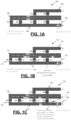
FIG. 1A is a map depicting an example operating environment 100 at an airport or other aerodrome. The example operating environment 100 includes a takeoff runway 102, a taxiway A (104) and a taxiway B (106) on which an aircraft 108 traverses to reach the takeoff runway 102, and a plurality of runway intersections (A3, A4, B1, B2, B3, and B4) for accessing the takeoff runway 102 from the taxiway A (104) and the taxiway B (106). The runway intersections B1, B2, B3, and B4 are potential takeoff intersections for the aircraft 108.
FIG. 1B is a map depicting an example operating environment 110 at an airport or other aerodrome. The example operating environment 110 includes a takeoff runway 112, a taxiway A (114) and a taxiway B (116) on which an aircraft 118 traverses to reach the takeoff runway 112, and a plurality of runway intersections (A3, A4, B1, B2, B3, and B4) for accessing the takeoff runway 112 from the taxiway A (114) and the taxiway B (116). The runway intersections B1, B2, B3, and B4 are potential takeoff intersections for the aircraft 108. In this example, runway intersections B1, B2, and B3 are each available as a takeoff intersection for the aircraft 118 and are so indicated by a valid intersection graphical element 117, and runway intersection B4 is not available as a takeoff intersection for the aircraft 118 and is so indicated by an invalid intersection graphical element 119. The valid intersection graphical element 117 may use various visual features such as color (e.g., green) to indicate that an associated runway intersection is available as a takeoff intersection. Similarly, the invalid intersection graphical element 119 may use various visual features such as color (e.g., red) to indicate that an associated runway intersection is not available as a takeoff intersection.
FIG. 1C is a map depicting an example operating environment 120 at an airport or other aerodrome. The example operating environment 120 includes a takeoff runway 122, a taxiway A (124) and a taxiway B (126) on which an aircraft 128 traverses to reach the takeoff runway 122, and a plurality of runway intersections (A3, A4, B1, B2, B3, and B4) for accessing the takeoff runway 122 from the taxiway A (124) and the taxiway B (126). The runway intersections B1, B2, B3, and B4 are potential takeoff intersections for the aircraft 108.
In this example, runway intersections B1, B2, and B3 are each available as a takeoff intersection for the aircraft 128 and are so indicated by a valid intersection graphical element 127, and runway intersection B4 is not available as a takeoff intersection for the aircraft 128 and is so indicated by an invalid intersection graphical element 129. The runway intersections B1, B2, and B3 are available as takeoff intersections for the aircraft 128 because they each have a corrected runway length that is long enough for use by the aircraft 128 for takeoff, wherein the corrected runway length is equal to a nominal runway length plus an elevation correction, a temperature correction, and a gradient correction, and wherein the nominal runway length is determined based on the actual length of the runway from the runway intersection to the end of the runway. The runway intersection B4 is not available as a takeoff intersection for the aircraft 128 because it has a corrected runway length that is not long enough for use by the aircraft 128 for takeoff. The valid intersection graphical element 127 may use various visual features such as color (e.g., green) to indicate that an associated runway intersection is available as a takeoff intersection. Similarly, the invalid intersection graphical element 129 may use various visual features such as color (e.g., red) to indicate that an associated runway intersection is not available as a takeoff intersection.
In this example, a corrected runway length graphical indicator 131 of a corrected runway length is provided adjacent to the runway intersection B4. This corrected runway length graphical indicator 131 provides a corrected runway length. The example corrected runway length graphical indicator 131 indicates that the corrected runway length at runway intersection is 7500 meters. Although, in this example, the corrected runway length graphical indicator 131 is only provided at the runway intersection B4, which is not available as a takeoff intersection, in other examples, the corrected runway length graphical indicator 131 may be provided at all or some of the other runway intersections (A1, A2, B1, B2, B3) including those runway intersections that are available as a takeoff intersection.
Also, in this example, a takeoff direction indicator 133 is provided adjacent to the runway intersection B4. This takeoff direction indicator 133 provides an indication of the direction to the end of the runway. Although, in this example, the takeoff direction indicator 133 is only provided at the runway intersection B4, which is not available as a takeoff intersection, in other examples, the takeoff direction indicator 133 may be provided at all or some of the other runway intersections (A1, A2, B1, B2, B3) including those runway intersections that are available as a takeoff intersection.
FIG. 2 is a block diagram depicting an example valid takeoff runway intersection identification system 200. The example valid runway intersection identification system 200 includes a valid takeoff runway intersection controller 202 that is configured to identify valid takeoff runway intersections and invalid takeoff runway intersections to a flight crew via a display device 204. The example valid takeoff runway intersection controller 202 is configured to receive aircraft parameters (such as aircraft type and aircraft weight) and runway parameter information (such as actual runway length at various runway intersections, runway temperature, runway elevation, runway gradient) via onboard aircraft systems 206 and databases 208. The example valid takeoff runway intersection controller 202 is configured to use the aircraft parameters and runway parameter information to estimate a runway length required for takeoff based on the aircraft parameters, estimate a corrected runway length at each of a plurality of runway intersections by applying an elevation correction, a temperature correction, and a gradient (e.g., runway slope) correction to a nominal runway length for the runway intersection, and determine, based on the estimated runway length required for takeoff and the corrected runway length at each of the plurality of runway intersections, each valid runway intersection from the plurality of runway intersections whose corrected runway length is long enough for use by the aircraft for takeoff and each invalid runway intersection from the plurality of runway intersections whose corrected runway length is not long enough for use by the aircraft for takeoff. The example valid takeoff runway intersection controller 202 is further configured to signal the display device 204 to display on a map depicting the takeoff runway at least an invalid intersection icon adjacent to each invalid runway intersection. The display device 204 may be a primary flight display (PFD), Navigation display (ND), heads up display (HUD), heads down display (HDD), an electronic flight bag (EFB), a tablet computer, a smartphone, a wearable device, or some other device for displaying messages in an aircraft cockpit.
The valid takeoff runway intersection controller 202 includes at least one processor and a computer-readable storage device or media encoded with programming instructions for configuring the controller. The processor may be any custom-made or commercially available processor, a central processing unit (CPU), a graphics processing unit (GPU), an application specific integrated circuit (ASIC), a field programmable gate array (FPGA), an auxiliary processor among several processors associated with the controller, a semiconductor-based microprocessor (in the form of a microchip or chip set), any combination thereof, or generally any device for executing instructions.
The computer readable storage device or media may include volatile and nonvolatile storage in read-only memory (ROM), random-access memory (RAM), and keep-alive memory (KAM), for example. KAM is a persistent or non-volatile memory that may be used to store various operating variables while the processor is powered down. The computer-readable storage device or media may be implemented using any of a number of known memory devices such as PROMs (programmable read-only memory), EPROMs (electrically PROM), EEPROMs (electrically erasable PROM), flash memory, or any other electric, magnetic, optical, or combination memory devices capable of storing data, some of which represent executable programming instructions, used by the controller.
To estimate a corrected runway length at a runway intersection, the takeoff runway intersection controller 202 is configured to estimate the elevation correction by multiplying a nominal runway length by a first factor, wherein the nominal runway length is determined based on the length of the runway from the runway intersection to the end of the runway. The takeoff runway intersection controller 202 is further configured to estimate the temperature correction by multiplying the nominal runway length by a second factor and estimate the gradient correction by multiplying the nominal runway length by a third factor. The takeoff runway intersection controller 202 estimates the corrected runway length as equating the corrected runway length to the nominal runway length plus the elevation correction, the temperature correction, and the gradient correction.
In one example, the first factor is based on a first fixed percentage increase per each fixed altitude range increase above sea level at the takeoff runway, the second factor is based on a second fixed percentage increase per fixed amount of temperature increase at the takeoff runway, and the third factor is based on a third fixed percentage increase per fixed degree of effective gradient when the combined elevation correction and temperature correction remains less than a fourth fixed percentage of the nominal runway length. In another example, the first factor is seven percent (7%) per 300 meter altitude above mean sea level (MSL), the second factor is one percent (1%) for every one-degree Celsius rise in Airport Reference Temperature (ART), and the third factor is 20 percent (20%) for every one percent of the effective gradient when the combined elevation correction and temperature correction remains less than 35 percent (35%) of the nominal takeoff runway length.
The example takeoff runway intersection controller 202 is configured to generate a takeoff runway map (e.g., operating environment 100/110/120) that graphically depicts the takeoff runway (e.g., takeoff runway 102/112/122), a taxiway (e.g., taxiway 106/116/126) on which the aircraft (e.g., aircraft 108/118/128) traverses to reach the takeoff runway, the runway intersections (e.g., B1 (107/117/127), B2 (107/117/127), B3 (107/117/127), and B4 (109/119/129)) from the taxiway to the takeoff runway, an aircraft graphical element 108/118/128 representative of the aircraft, a valid intersection graphical element (e.g., 117/127) for identifying each valid runway intersection and an invalid intersection graphical element (e.g., 119/129) for identifying each invalid runway intersection. The example takeoff runway intersection controller 202 is configured to further configured to signal an aircraft display device (e.g., display device 204) to display the takeoff runway map.
In one example, the takeoff runway intersection controller 202 is further configured to position an indication (e.g., corrected runway length graphical indicator 131) of the corrected runway length for each runway intersection adjacent to the runway intersection. In another example, the takeoff runway intersection controller 202 is further configured to position a takeoff direction indicator (e.g., takeoff direction indicator 133) for each runway intersection adjacent to the runway intersection. In another example, the takeoff runway intersection controller 202 is further configured to provide an alert on a cockpit display when the corrected runway length for a runway intersection selected using the cockpit display by a flight crew member is not long enough for use by the aircraft for takeoff.
FIG. 3 is a diagram depicting an example 3D (three dimensional) AMM (airport moving map) display 300. In the example 3D AMM display 300, illustrated are an icon 302 representative of an ownship aircraft, a first taxiway 304 on which the ownship is traversing, a second taxiway 306 on which the ownship is to traverse before turning onto a takeoff runway 308, an intersection 310 from the second taxiway 306 and the takeoff runway 308 that is identified by an intersection indicator A13 and that has been selected for use by the ownship for turning onto the runway 308. The intersection 310 may have been automatically selected by ATC, manually chosen by the flight crew, and/or received via a CPDLC message.
In this example, a takeoff runway intersection controller (e.g., controller 202) in the ownship has used ownship parameters and runway parameter information to estimate a runway length required for takeoff and has estimated a corrected runway length at the intersection 310 by applying an elevation correction, a temperature correction, and a gradient correction to a nominal runway length for the runway intersection 310, and determined, based on the estimated runway length required for takeoff and the corrected runway length at the runway intersection 310 is an invalid runway intersection because its corrected runway length is not long enough for use by the ownship for takeoff. The takeoff runway intersection controller has further provided an indication, through causing the intersection indicator A13 to be displayed in a visually distinguishable manner (e.g., bold type, highlighting, color such as red), that the runway intersection 310 identified as runway intersection A13 is not available as takeoff intersection.
FIG. 4 is a diagram depicting an example 2D (two dimensional) AMM display 400. In the example 2D AMM display 400, illustrated are an icon 402 representative of an ownship aircraft, a first taxiway 404 on which the ownship is traversing, a second taxiway 406 on which the ownship is to traverse before turning onto a takeoff runway 408, an intersection 410 from the second taxiway 406 and the takeoff runway 408 that is identified by an intersection indicator A13 and that has been selected for use by the ownship for turning onto the runway 408. The intersection 410 may have been automatically selected by ATC, manually chosen by the flight crew, and/or received via a CPDLC message.
In this example, a takeoff runway intersection controller (e.g., controller 202) in the ownship has used ownship parameters and runway parameter information to estimate a runway length required for takeoff and has estimated a corrected runway length at the intersection 410 by applying an elevation correction, a temperature correction, and a gradient correction to a nominal runway length for the runway intersection 410, and determined, based on the estimated runway length required for takeoff and the corrected runway length at the runway intersection 410 is an invalid runway intersection because its corrected runway length is not long enough for use by the ownship for takeoff. The takeoff runway intersection controller has further provided an indication, through causing the intersection indicator A13 to be displayed in a visually distinguishable manner (e.g., bold type, highlighting, color such as red), that the runway intersection 410 identified as runway intersection A13 is not available as takeoff intersection.
FIG. 5 is a process flow chart depicting an example process 500 in an example takeoff runway intersection controller (e.g., controller 202) in an aircraft for identifying valid runway intersections for takeoff. The order of operation within the process 500 is not limited to the sequential execution as illustrated in the figure, but may be performed in one or more varying orders as applicable and in accordance with the present disclosure.
The example process 500 includes estimating a runway length required for takeoff based on aircraft parameters (e.g., aircraft type, aircraft weight, etc.) (operation 502) and includes estimating, at each of a plurality of runway intersections, a corrected runway length at the runway intersection by applying an elevation correction, a temperature correction, and a gradient correction (operation 504). Estimating a corrected runway length may comprise: estimating the elevation correction by multiplying a nominal runway length by a first factor, wherein the nominal runway length is based on the length of the runway from the runway intersection to the end of the runway; estimating the temperature correction by multiplying the nominal runway length by a second factor; estimating the gradient correction by multiplying the nominal runway length by a third factor; and making the corrected runway length equal to the nominal runway length plus the elevation correction, the temperature correction, and the gradient correction.
In one example, the first factor is based on a first fixed percentage increase per each fixed altitude range increase above sea level at the takeoff runway, the second factor is based on a second fixed percentage increase per fixed amount of temperature increase at the takeoff runway, and the third factor is based on a third fixed percentage increase per fixed degree of effective gradient when the combined elevation correction and temperature correction remains less than a fourth fixed percentage of the nominal runway length.
In one example, the first factor is seven percent (7%) per 300 meter altitude above mean sea level (MSL), the second factor is one percent (1%) for every one-degree Celsius rise in Airport Reference Temperature (ART), and the third factor is 20 percent (20%) for every one percent of the effective gradient when the combined elevation correction and temperature correction remains less than 35 percent (35%) of the nominal takeoff runway length.
The example process 500 includes determining each valid runway intersection whose corrected runway length is long enough for use for takeoff and each invalid runway intersection whose corrected runway length is not long enough for use by the aircraft for takeoff (operation 506) and signaling an aircraft display device to display on a map depicting the takeoff runway an invalid intersection icon adjacent to each invalid runway intersection (operation 508).
The subject matter described herein discloses apparatus, systems, techniques, and articles for identifying valid runway intersections for takeoff. In one embodiment, a flight deck system for identifying valid runway intersections for takeoff is provided. The flight deck system comprises an aircraft display device in an aircraft and a controller. The controller is configured to: estimate a runway length required for takeoff based on aircraft parameters (e.g., aircraft type, aircraft weight, etc.); estimate, at each of a plurality of runway intersections, a corrected runway length at the runway intersection by applying an elevation correction, a temperature correction, and a gradient correction; determine, based on the estimated runway length required for takeoff and the corrected runway length at each of the plurality of runway intersections, each valid runway intersection from the plurality of runway intersections whose corrected runway length is long enough for use by the aircraft for takeoff and each invalid runway intersection from the plurality of runway intersections whose corrected runway length is not long enough for use by the aircraft for takeoff; and signal the aircraft display device to display on a map depicting the takeoff runway an invalid intersection icon adjacent to each invalid runway intersection.
These aspects and other embodiments may include one or more of the following features. To estimate a corrected runway length the controller may be configured to estimate the elevation correction by multiplying a nominal runway length by a first factor, wherein the nominal runway length is based on the length of the runway from the runway intersection to the end of the runway; estimate the temperature correction by multiplying the nominal runway length by a second factor; and estimate the gradient correction by multiplying the nominal runway length by a third factor; wherein the corrected runway length is equal to the nominal runway length plus the elevation correction, the temperature correction, and the gradient correction. The first factor may be based on a first fixed percentage increase per each fixed altitude range increase above sea level at the takeoff runway, the second factor may be based on a second fixed percentage increase per fixed amount of temperature increase at the takeoff runway, and the third factor may be based on a third fixed percentage increase per fixed degree of effective gradient when the combined elevation correction and temperature correction remains less than a fourth fixed percentage of the nominal runway length. The first factor may be seven percent per 300 meter altitude above mean sea level (MSL), the second factor may be one percent for every one degree Celsius rise in Airport Reference Temperature (ART), and the third factor may be 20 percent for every one percent of the effective gradient when the combined elevation correction and temperature correction remains less than 35 percent of the nominal takeoff runway length. The controller may be further configured to: generate a takeoff runway map that graphically depicts the takeoff runway, a taxiway on which the aircraft traverses to reach the takeoff runway, the runway intersections from the taxiway to the takeoff runway, an aircraft graphical element representative of the aircraft, a valid intersection graphical element for identifying each valid runway intersection and an invalid intersection graphical element for identifying each invalid runway intersection; and signal the aircraft display device to display the takeoff runway map. The controller may be further configured position an indication of the corrected runway length for each runway intersection adjacent to the runway intersection. The controller may be further configured to position a takeoff direction indicator for each runway intersection adjacent to the runway intersection. The controller may be further configured to provide an alert on a cockpit display when the corrected runway length for a runway intersection selected using the cockpit display by a flight crew member is not long enough for use by the aircraft for takeoff.
In another embodiment, a method in a flight deck system in an aircraft for identifying valid runway intersections for takeoff is provided. The method comprises: estimating a runway length required for takeoff based on aircraft parameters (e.g., aircraft type, aircraft weight, etc.); estimating, at each of a plurality of runway intersections, a corrected runway length at the runway intersection by applying an elevation correction, a temperature correction, and a gradient correction; determining, based on the estimated runway length required for takeoff and the corrected runway length at each of the plurality of runway intersections, each valid runway intersection from the plurality of runway intersections whose corrected runway length is long enough for use by the aircraft for takeoff and each invalid runway intersection from the plurality of runway intersections whose corrected runway length is not long enough for use by the aircraft for takeoff; and signaling an aircraft display device to display on a map depicting the takeoff runway an invalid intersection icon adjacent to each invalid runway intersection.
These aspects and other embodiments may include one or more of the following features. Estimating a corrected runway length may comprise: estimating the elevation correction by multiplying a nominal runway length by a first factor, wherein the nominal runway length is based on the length of the runway from the runway intersection to the end of the runway; estimating the temperature correction by multiplying the nominal runway length by a second factor; estimating the gradient correction by multiplying the nominal runway length by a third factor; and making the corrected runway length equal to the nominal runway length plus the elevation correction, the temperature correction, and the gradient correction. The first factor may be based on a first fixed percentage increase per each fixed altitude range increase above sea level at the takeoff runway, the second factor may be based on a second fixed percentage increase per fixed amount of temperature increase at the takeoff runway, and the third factor may be based on a third fixed percentage increase per fixed degree of effective gradient when the combined elevation correction and temperature correction remains less than a fourth fixed percentage of the nominal runway length. The first factor may be seven percent per 300 meter altitude above mean sea level (MSL), the second factor may be one percent for every one degree Celsius rise in Airport Reference Temperature (ART), and the third factor may be 20 percent for every one percent of the effective gradient when the combined elevation correction and temperature correction remains less than 35 percent of the nominal takeoff runway length. The method may further comprise: generating a takeoff runway map that graphically depicts the takeoff runway, a taxiway on which the aircraft traverses to reach the takeoff runway, the runway intersections from the taxiway to the takeoff runway, an aircraft graphical element representative of the aircraft, a valid intersection graphical element for identifying each valid runway intersection and an invalid intersection graphical element for identifying each invalid runway intersection; and signaling the aircraft display device to display the takeoff runway map. The method may further comprise positioning an indication of the corrected runway length for each runway intersection adjacent to the runway intersection. The method may further comprise positioning a takeoff direction indicator for each runway intersection adjacent to the runway intersection. The method may further comprise providing an alert on a cockpit display when the corrected runway length for a runway intersection selected using the cockpit display by a flight crew member is not long enough for use by the aircraft for takeoff.
In another embodiment, a non-transitory computer readable medium encoded with instructions configurable to cause a controller in an aircraft to perform a method for identifying valid runway intersections for takeoff is provided. The method comprises: estimating a runway length required for takeoff based on aircraft parameters (e.g., aircraft type, aircraft weight, etc.); estimating, at each of a plurality of runway intersections, a corrected runway length at the runway intersection by applying an elevation correction, a temperature correction, and a gradient correction; determining, based on the estimated runway length required for takeoff and the corrected runway length at each of the plurality of runway intersections, each valid runway intersection from the plurality of runway intersections whose corrected runway length is long enough for use by the aircraft for takeoff and each invalid runway intersection from the plurality of runway intersections whose corrected runway length is not long enough for use by the aircraft for takeoff; and signaling an aircraft display device to display on a map depicting the takeoff runway an invalid intersection icon adjacent to each invalid runway intersection.
These aspects and other embodiments may include one or more of the following features. Estimating a corrected runway length may comprise: estimating the elevation correction by multiplying a nominal runway length by a first factor, wherein the nominal runway length is based on the length of the runway from the runway intersection to the end of the runway; estimating the temperature correction by multiplying the nominal runway length by a second factor; estimating the gradient correction by multiplying the nominal runway length by a third factor; and making the corrected runway length equal to the nominal runway length plus the elevation correction, the temperature correction, and the gradient correction. The first factor may be based on a first fixed percentage increase per each fixed altitude range increase above sea level at the takeoff runway, the second factor may be based on a second fixed percentage increase per fixed amount of temperature increase at the takeoff runway, and the third factor may be based on a third fixed percentage increase per fixed degree of effective gradient when the combined elevation correction and temperature correction remains less than a fourth fixed percentage of the nominal runway length. The first factor may be seven percent per 300 meter altitude above mean sea level (MSL), the second factor may be one percent for every one degree Celsius rise in Airport Reference Temperature (ART), and the third factor may be 20 percent for every one percent of the effective gradient when the combined elevation correction and temperature correction remains less than 35 percent of the nominal takeoff runway length. The method may further comprise: generating a takeoff runway map that graphically depicts the takeoff runway, a taxiway on which the aircraft traverses to reach the takeoff runway, the runway intersections from the taxiway to the takeoff runway, an aircraft graphical element representative of the aircraft, a valid intersection graphical element for identifying each valid runway intersection and an invalid intersection graphical element for identifying each invalid runway intersection; and signaling the aircraft display device to display the takeoff runway map. The method may further comprise positioning an indication of the corrected runway length for each runway intersection adjacent to the runway intersection. The method may further comprise positioning a takeoff direction indicator for each runway intersection adjacent to the runway intersection. The method may further comprise providing an alert on a cockpit display when the corrected runway length for a runway intersection selected using the cockpit display by a flight crew member is not long enough for use by the aircraft for takeoff.
In another embodiment, a flight deck system for identifying valid runway intersections for takeoff is provided. The flight deck system comprises a display device and a controller. The controller is configured to: estimate a runway length required for takeoff based on aircraft parameters (e.g., aircraft type, aircraft weight, etc.); and estimate, at each of a plurality of runway intersections, a corrected runway length at the runway intersection by applying an elevation correction, a temperature correction, and a gradient correction. To estimate a corrected runway length at the runway intersection the controller is configured to estimate the elevation correction by multiplying a nominal runway length by seven percent per 300 meter altitude above mean sea level (MSL), estimate the temperature correction by multiplying the nominal runway length by one percent for every one degree Celsius rise in Airport Reference Temperature (ART), and estimate the gradient correction by multiplying the nominal runway length by 20 percent for every one percent of the effective gradient when the combined elevation correction and temperature correction remains less than 35 percent of the nominal runway length, wherein the corrected runway length is equal to the nominal runway length plus the elevation correction, the temperature correction, and gradient correction. The controller is further configured to determine, based on the estimated runway length required for takeoff and the corrected runway length at each of the plurality of runway intersection, each valid runway intersection whose corrected runway length is long enough for use by the aircraft for takeoff and each invalid runway intersection whose corrected runway length is not long enough for use by the aircraft for takeoff; generate a runway display that shows the takeoff runway, the runway intersections, an icon representative of the aircraft, a first indicator that identifies any valid runway intersections and a second indicator that identifies any invalid runway intersections; position the available runway length and a takeoff direction indicator for a runway intersection on the runway display adjacent the runway intersection; signal a display device to display the runway display; and provide an alert when the corrected runway length for a selected runway intersection is not long enough for use by the aircraft for takeoff.
Those of skill in the art will appreciate that the various illustrative logical blocks, modules, circuits, and algorithm steps described in connection with the embodiments disclosed herein may be implemented as electronic hardware, computer software, or combinations of both. Some of the embodiments and implementations are described above in terms of functional and/or logical block components (or modules) and various processing steps. However, it should be appreciated that such block components (or modules) may be realized by any number of hardware, software, and/or firmware components configured to perform the specified functions. To clearly illustrate this interchangeability of hardware and software, various illustrative components, blocks, modules, circuits, and steps have been described above generally in terms of their functionality. Whether such functionality is implemented as hardware or software depends upon the particular application and design constraints imposed on the overall system. Skilled artisans may implement the described functionality in varying ways for each particular application, but such implementation decisions should not be interpreted as causing a departure from the scope of the present invention. For example, an embodiment of a system or a component may employ various integrated circuit components, e.g., memory elements, digital signal processing elements, logic elements, look-up tables, or the like, which may carry out a variety of functions under the control of one or more microprocessors or other control devices. In addition, those skilled in the art will appreciate that embodiments described herein are merely exemplary implementations.
The various illustrative logical blocks, modules, and circuits described in connection with the embodiments disclosed herein may be implemented or performed with a general purpose processor, a digital signal processor (DSP), an application specific integrated circuit (ASIC), a field programmable gate array (FPGA) or other programmable logic device, discrete gate or transistor logic, discrete hardware components, or any combination thereof designed to perform the functions described herein. A general-purpose processor may be a microprocessor, but in the alternative, the processor may be any conventional processor, controller, microcontroller, or state machine. A processor may also be implemented as a combination of computing devices, e.g., a combination of a DSP and a microprocessor, a plurality of microprocessors, one or more microprocessors in conjunction with a DSP core, or any other such configuration.
The steps of a method or algorithm described in connection with the embodiments disclosed herein may be embodied directly in hardware, in a software module executed by a processor, or in a combination of the two. A software module may reside in RAM memory, flash memory, ROM memory, EPROM memory, EEPROM memory, registers, hard disk, a removable disk, a CD-ROM, or any other form of storage medium known in the art. An exemplary storage medium is coupled to the processor such that the processor can read information from, and write information to, the storage medium. In the alternative, the storage medium may be integral to the processor. The processor and the storage medium may reside in an ASIC. The ASIC may reside in a user terminal. In the alternative, the processor and the storage medium may reside as discrete components in a user terminal.
In this document, relational terms such as first and second, and the like may be used solely to distinguish one entity or action from another entity or action without necessarily requiring or implying any actual such relationship or order between such entities or actions. Numerical ordinals such as “first,” “second,” “third,” etc. simply denote different singles of a plurality and do not imply any order or sequence unless specifically defined by the claim language. The sequence of the text in any of the claims does not imply that process steps must be performed in a temporal or logical order according to such sequence unless it is specifically defined by the language of the claim. The process steps may be interchanged in any order without departing from the scope of the invention as long as such an interchange does not contradict the claim language and is not logically nonsensical.
Furthermore, depending on the context, words such as “connect” or “coupled to” used in describing a relationship between different elements do not imply that a direct physical connection must be made between these elements. For example, two elements may be connected to each other physically, electronically, logically, or in any other manner, through one or more additional elements.
While at least one exemplary embodiment has been presented in the foregoing detailed description of the invention, it should be appreciated that a vast number of variations exist. It should also be appreciated that the exemplary embodiment or exemplary embodiments are only examples, and are not intended to limit the scope, applicability, or configuration of the invention in any way. Rather, the foregoing detailed description will provide those skilled in the art with a convenient road map for implementing an exemplary embodiment of the invention. It being understood that various changes may be made in the function and arrangement of elements described in an exemplary embodiment without departing from the scope of the invention as set forth in the appended claims.

Claims (20)

What is claimed is:
1. A flight deck system for identifying valid runway intersections for takeoff, the flight deck system comprising:
an aircraft display device in an aircraft; and
a controller configured to:
estimate a runway length required for takeoff based on aircraft parameters;
estimate, at each of a plurality of runway intersections, a corrected runway length available for takeoff at the runway intersection by applying an elevation correction, a temperature correction, and a gradient correction to an actual length of the runway from the runway intersection to the end of the runway;
determine, based on the estimated runway length required for takeoff and the corrected runway length available for takeoff at each of the plurality of runway intersections, each valid runway intersection from the plurality of runway intersections whose corrected runway length is long enough for use by the aircraft for takeoff and each invalid runway intersection from the plurality of runway intersections whose corrected runway length is not long enough for use by the aircraft for takeoff; and
signal the aircraft display device to display on a map depicting the takeoff runway an invalid intersection icon adjacent to each invalid runway intersection.
2. The flight deck system of claim 1, wherein to estimate the controller is configured to:
estimate the elevation correction for determining the corrected runway length available for takeoff by multiplying the actual length of the runway from the runway intersection to the end of the runway by a first factor;
estimate the temperature correction for determining the corrected runway length available for takeoff by multiplying the actual length of the runway from the runway intersection to the end of the runway by a second factor; and
estimate the gradient correction for determining the corrected runway length available for takeoff by multiplying the actual length of the runway from the runway intersection to the end of the runway by a third factor;
wherein the corrected runway length is equal to the actual length of the runway from the runway intersection to the end of the runway plus the elevation correction, the temperature correction, and the gradient correction.
3. The flight deck system of claim 2, wherein:
the first factor is based on a first fixed percentage per a fixed altitude level above sea level at the takeoff runway;
the second factor is based on a second fixed percentage per fixed amount of temperature increase at the takeoff runway; and
the third factor is based on a third fixed percentage per fixed percentage of effective gradient when a combined elevation correction and temperature correction remains less than a fourth fixed percentage of the actual length of the runway from the runway intersection to the end of the runway.
4. The flight deck system of claim 3, wherein:
the first factor is seven percent per 300 meter altitude above mean sea level (MSL);
the second factor is one percent for every one-degree Celsius rise in Airport Reference Temperature (ART); and
the third factor is 20 percent for every one percent of the effective gradient when the combined elevation correction and temperature correction remains less than 35 percent of the nominal takeoff runway length.
5. The flight deck system of claim 1, wherein the controller is further configured to:
generate a takeoff runway map that graphically depicts the takeoff runway, a taxiway on which the aircraft traverses to reach the takeoff runway, the runway intersections from the taxiway to the takeoff runway, an aircraft graphical element representative of the aircraft, a valid intersection graphical element for identifying each valid runway intersection and an invalid intersection graphical element for identifying each invalid runway intersection; and
signal the aircraft display device to display the takeoff runway map.
6. The flight deck system of claim 5, wherein the controller is further configured position an indication of the corrected runway length for each runway intersection adjacent to the runway intersection.
7. The flight deck system of claim 6, wherein the controller is further configured to position a takeoff direction indicator for each runway intersection adjacent to the runway intersection.
8. The flight deck system of claim 1, wherein the controller is further configured to provide an alert on a cockpit display when the corrected runway length for a runway intersection selected using the cockpit display by a flight crew member is not long enough for use by the aircraft for takeoff.
9. A method in a flight deck system in an aircraft for identifying valid runway intersections for takeoff, the method comprising:
estimating a runway length required for takeoff based on aircraft parameters;
estimating, at each of a plurality of runway intersections, a corrected runway length available for takeoff at the runway intersection by applying an elevation correction, a temperature correction, and a gradient correction to an actual length of the runway from the runway intersection to the end of the runway;
determining, based on the estimated runway length required for takeoff and the corrected runway length available for takeoff at each of the plurality of runway intersections, each valid runway intersection from the plurality of runway intersections whose corrected runway length is long enough for use by the aircraft for takeoff and each invalid runway intersection from the plurality of runway intersections whose corrected runway length is not long enough for use by the aircraft for takeoff; and
signaling an aircraft display device to display on a map depicting the takeoff runway an invalid intersection icon adjacent to each invalid runway intersection.
10. The method of claim 9, wherein estimating a corrected runway length comprises:
estimating the elevation correction for determining the corrected runway length available for takeoff by multiplying the actual length of the runway from the runway intersection to the end of the runway by a first factor;
estimating the temperature correction for determining the corrected runway length available for takeoff by multiplying the actual length of the runway from the runway intersection to the end of the runway by a second factor;
estimating the gradient correction for determining the corrected runway length available for takeoff by multiplying the actual length of the runway from the runway intersection to the end of the runway by a third factor; and
making the corrected runway length equal to the actual length of the runway from the runway intersection to the end of the runway plus the elevation correction, the temperature correction, and the gradient correction.
11. The method of claim 10, wherein:
the first factor is based on a first fixed percentage per a fixed altitude level above sea level at the takeoff runway;
the second factor is based on a second fixed percentage per fixed amount of temperature increase at the takeoff runway; and
the third factor is based on a third fixed percentage per fixed percentage of effective gradient when a combined elevation correction and temperature correction remains less than a fourth fixed percentage of the actual length of the runway from the runway intersection to the end of the runway.
12. The method of claim 11, wherein:
the first factor is seven percent per 300 meter altitude above mean sea level (MSL);
the second factor is one percent for every one-degree Celsius rise in Airport Reference Temperature (ART); and
the third factor is 20 percent for every one percent of the effective gradient when the combined elevation correction and temperature correction remains less than 35 percent of the nominal takeoff runway length.
13. The method of claim 9, further comprising:
generating a takeoff runway map that graphically depicts the takeoff runway, a taxiway on which the aircraft traverses to reach the takeoff runway, the runway intersections from the taxiway to the takeoff runway, an aircraft graphical element representative of the aircraft, a valid intersection graphical element for identifying each valid runway intersection and an invalid intersection graphical element for identifying each invalid runway intersection; and
signaling the aircraft display device to display the takeoff runway map.
14. The method of claim 13, further comprising positioning an indication of the corrected runway length for each runway intersection adjacent to the runway intersection.
15. The method of claim 14, further comprising positioning a takeoff direction indicator for each runway intersection adjacent to the runway intersection.
16. The method of claim 9, further comprising providing an alert on a cockpit display when the corrected runway length for a runway intersection selected using the cockpit display by a flight crew member is not long enough for use by the aircraft for takeoff.
17. A non-transitory computer readable medium encoded with instructions configurable to cause a controller in an aircraft to perform a method for identifying valid runway intersections for takeoff, the method comprising:
estimating a runway length required for takeoff based on aircraft parameters;
estimating, at each of a plurality of runway intersections, a corrected runway length available for takeoff at the runway intersection by applying an elevation correction, a temperature correction, and a gradient correction to an actual length of the runway from the runway intersection to the end of the runway;
determining, based on the estimated runway length required for takeoff and the corrected runway length available for takeoff at each of the plurality of runway intersections, each valid runway intersection from the plurality of runway intersections whose corrected runway length is long enough for use by the aircraft for takeoff and each invalid runway intersection from the plurality of runway intersections whose corrected runway length is not long enough for use by the aircraft for takeoff; and
signaling an aircraft display device to display on a map depicting the takeoff runway an invalid intersection icon adjacent to each invalid runway intersection.
18. The non-transitory computer readable medium of claim 17, wherein estimating a corrected runway length comprises:
estimating the elevation correction for determining the corrected runway length available for takeoff by multiplying the actual length of the runway from the runway intersection to the end of the runway by a first factor;
estimating the temperature correction for determining the corrected runway length available for takeoff by multiplying the actual length of the runway from the runway intersection to the end of the runway by a second factor;
estimating the gradient correction for determining the corrected runway length available for takeoff by multiplying the actual length of the runway from the runway intersection to the end of the runway by a third factor; and
making the corrected runway length equal to the actual length of the runway from the runway intersection to the end of the runway plus the elevation correction, the temperature correction, and the gradient correction.
19. The non-transitory computer readable medium of claim 18, wherein:
the first factor is based on a first fixed percentage per a fixed altitude level above sea level at the takeoff runway;
the second factor is based on a second fixed percentage per fixed amount of temperature increase at the takeoff runway; and
the third factor is based on a third fixed percentage per fixed percentage of effective gradient when a combined elevation correction and temperature correction remains less than a fourth fixed percentage of the actual length of the runway from the runway intersection to the end of the runway.
20. The non-transitory computer readable medium of claim 19, wherein:
the first factor is seven percent per 300 meter altitude above mean sea level (MSL);
the second factor is one percent for every one-degree Celsius rise in Airport Reference Temperature (ART); and
the third factor is 20 percent for every one percent of the effective gradient when the combined elevation correction and temperature correction remains less than 35 percent of the nominal takeoff runway length.
US17/647,270 2021-10-28 2022-01-06 Systems and methods for monitoring and providing alerts for takeoff runway intersections Active 2042-10-20 US12094354B2 (en)

Priority Applications (1)

Application Number Priority Date Filing Date Title
EP22201122.3A EP4174821B1 (en) 2021-10-28 2022-10-12 Systems and methods for monitoring and providing alerts for takeoff runway intersections

Applications Claiming Priority (2)

Application Number Priority Date Filing Date Title
IN202111049325 2021-10-28

Publications (2)

Publication Number Publication Date
US20230136572A1 US20230136572A1 (en) 2023-05-04
US12094354B2 true US12094354B2 (en) 2024-09-17

Family

ID=86146583

Family Applications (1)

Application Number Title Priority Date Filing Date
US17/647,270 Active 2042-10-20 US12094354B2 (en) 2021-10-28 2022-01-06 Systems and methods for monitoring and providing alerts for takeoff runway intersections

Country Status (1)

Country Link
US (1) US12094354B2 (en)

Families Citing this family (1)

* Cited by examiner, † Cited by third party
Publication number Priority date Publication date Assignee Title
US12249243B2 (en) * 2022-03-07 2025-03-11 The Boeing Company Anomaly determination in geospatial data

Citations (18)

* Cited by examiner, † Cited by third party
Publication number Priority date Publication date Assignee Title
US20040167685A1 (en) * 2003-02-24 2004-08-26 Ryan Dean E. Runway overrun monitor and method for monitoring runway overruns
US20080215198A1 (en) 2006-09-22 2008-09-04 Richards Robert E Method and apparatus for providing takeoff runway information and predicting end of runway overrun
US20080275642A1 (en) * 2007-05-04 2008-11-06 Clark Samuel T Methods and systems for displaying airport moving map information
US7590484B2 (en) 2007-08-06 2009-09-15 Gellert Daniel G Safe runway aircraft arrival and departure system using split runway design
US20120209458A1 (en) 2011-02-14 2012-08-16 Honeywell International Inc. Systems and methods for verifying an available runway length
US8441376B1 (en) 2010-09-29 2013-05-14 Rockwell Collins, Inc. System, module, and method for presenting surface symbology on an aircraft display unit
US20130231853A1 (en) 2010-02-09 2013-09-05 Honeywell International Inc. System and methods for rendering taxiway and runway signage in a synthetic display of an airport field
US20130271300A1 (en) 2012-04-12 2013-10-17 Honeywell International Inc. Systems and methods for improving runway awareness with takeoff and landing performance data
US20140343764A1 (en) * 2013-05-14 2014-11-20 Thales Method and System for Monitoring Aircraft Flight Phase on Approach to a Runway
US9117370B1 (en) 2014-03-12 2015-08-25 Honeywell International Inc. System and method for identifying runway position during an intersection takeoff
US9646501B2 (en) 2015-07-14 2017-05-09 Honeywell International Inc. System and method for integrating temporal data into flight management systems
US20180061243A1 (en) * 2013-01-23 2018-03-01 Iatas (Automatic Air Traffic Control) Ltd System and methods for automated airport air traffic control services
US20180107227A1 (en) * 2016-10-19 2018-04-19 Airbus Sas Revised speed advisory for an aircraft during flight based on holding time
US20180308367A1 (en) * 2015-12-21 2018-10-25 SZ DJI Technology Co., Ltd. Targeted flight restricted regions
US20190056740A1 (en) 2017-08-18 2019-02-21 The Boeing Company Process and Machine for Making a Runway Extension Speed for an Aircraft
US20190318639A1 (en) * 2017-03-14 2019-10-17 Architecture Technology Corporation Advisor System and Method
CN111968409A (en) 2020-07-31 2020-11-20 中国民航科学技术研究院 Aircraft takeoff stopping identification method and system based on real-time ADS-B data
EP3816972A1 (en) 2019-10-31 2021-05-05 Rockwell Collins, Inc. System and method to change svs mode

Patent Citations (21)

* Cited by examiner, † Cited by third party
Publication number Priority date Publication date Assignee Title
US20040167685A1 (en) * 2003-02-24 2004-08-26 Ryan Dean E. Runway overrun monitor and method for monitoring runway overruns
US20080215198A1 (en) 2006-09-22 2008-09-04 Richards Robert E Method and apparatus for providing takeoff runway information and predicting end of runway overrun
US20080275642A1 (en) * 2007-05-04 2008-11-06 Clark Samuel T Methods and systems for displaying airport moving map information
US7590484B2 (en) 2007-08-06 2009-09-15 Gellert Daniel G Safe runway aircraft arrival and departure system using split runway design
US20130231853A1 (en) 2010-02-09 2013-09-05 Honeywell International Inc. System and methods for rendering taxiway and runway signage in a synthetic display of an airport field
US8441376B1 (en) 2010-09-29 2013-05-14 Rockwell Collins, Inc. System, module, and method for presenting surface symbology on an aircraft display unit
US20120209458A1 (en) 2011-02-14 2012-08-16 Honeywell International Inc. Systems and methods for verifying an available runway length
US20130271300A1 (en) 2012-04-12 2013-10-17 Honeywell International Inc. Systems and methods for improving runway awareness with takeoff and landing performance data
US20180061243A1 (en) * 2013-01-23 2018-03-01 Iatas (Automatic Air Traffic Control) Ltd System and methods for automated airport air traffic control services
US20140343764A1 (en) * 2013-05-14 2014-11-20 Thales Method and System for Monitoring Aircraft Flight Phase on Approach to a Runway
US20150262493A1 (en) * 2014-03-12 2015-09-17 Honeywell International Inc. System and method for identifying runway position during an intersection takeoff
US9117370B1 (en) 2014-03-12 2015-08-25 Honeywell International Inc. System and method for identifying runway position during an intersection takeoff
US9646501B2 (en) 2015-07-14 2017-05-09 Honeywell International Inc. System and method for integrating temporal data into flight management systems
US20180308367A1 (en) * 2015-12-21 2018-10-25 SZ DJI Technology Co., Ltd. Targeted flight restricted regions
US20180107227A1 (en) * 2016-10-19 2018-04-19 Airbus Sas Revised speed advisory for an aircraft during flight based on holding time
US20190318639A1 (en) * 2017-03-14 2019-10-17 Architecture Technology Corporation Advisor System and Method
US20190056740A1 (en) 2017-08-18 2019-02-21 The Boeing Company Process and Machine for Making a Runway Extension Speed for an Aircraft
EP3816972A1 (en) 2019-10-31 2021-05-05 Rockwell Collins, Inc. System and method to change svs mode
US20220051578A1 (en) * 2019-10-31 2022-02-17 Rockwell Collins, Inc. System and Method to Change SVS Mode
CN111968409A (en) 2020-07-31 2020-11-20 中国民航科学技术研究院 Aircraft takeoff stopping identification method and system based on real-time ADS-B data
CN111968409B (en) 2020-07-31 2021-06-29 中国民航科学技术研究院 A method and system for aircraft aborted take-off recognition based on real-time ADS-B data

Non-Patent Citations (2)

* Cited by examiner, † Cited by third party
Title
Federal Aviation Administration: "Pilot's Handbook of Aeronautical Knowledge—Chapter 11: Aircraft Performance' In: Pilot's Handbook of Aeronautical Knowledge—Chapter 11: Aircraft Performance". Published Jan. 1, 2016 US Department of Transportation, XP93032504, Retrieved from the Internet: URL: https://www.faa.gov/sites/faa.gov/files/regulations_policies/handbook_manuals/aviation/phak/13_phak_ch11.pdf>.
Rastogi, Deepanshu, "Airport Runway Length: ESE & Gate CE / Gradeup, BYJU'S Exam Prep", downloaded from: https://byjusexamprep.com/AirportRailwayHarbourandPorts/AirportRailwayHarbourandPorts-i-82558360-ac8c-11e6-bf0d-8b7dbbd82825 on Sep. 28, 2021.

Also Published As

Publication number Publication date
US20230136572A1 (en) 2023-05-04

Similar Documents

Publication Publication Date Title
US10713960B1 (en) Presentation of 2D and 3D assisted visual separation information
US8600651B2 (en) Filtering of relevant traffic for display, enhancement, and/or alerting
EP3703036B1 (en) System and method for enabling automatic diversion management
WO2012145061A2 (en) Methods and systems for filtering traffic information for display
EP3816969A1 (en) System and method for calculating a turn to join a track behind a preceding aircraft while maintaining a specified spacing interval
EP2950295B1 (en) System and method for economizing flight expenditures during aircraft descent and approach
US11104449B2 (en) Significant weather advisory system
EP3144637A1 (en) Method and system for improving situational awareness of unanticipated yaw on a rotorcraft system
CA2984425C (en) Systems and methods for assisting with aircraft landing
US12094354B2 (en) Systems and methods for monitoring and providing alerts for takeoff runway intersections
EP4174821A1 (en) Systems and methods for monitoring and providing alerts for takeoff runway intersections
US8502701B2 (en) Runway status indicator
US12518641B2 (en) Systems and methods for generating avionic displays indicating wake turbulence
EP3796287A1 (en) System and method to monitor traffic and provide alert in fim-pa post planned termination point
US11749127B2 (en) System and method to provide progressive taxi instructions and alerts on cockpit display
US20130278628A1 (en) Methods and systems for representing segmented circle airport marker information on a cockpit display
US11790797B2 (en) Methods to initialize ground taxi clearance display
EP3961602B1 (en) System and method to provide progressive taxi instructions and alerts on cockpit display
US11348472B2 (en) System and method to automatically construct a flight plan from a data set for an aerial vehicle
EP3904832B1 (en) System and method to automatically construct a flight plan from a data set for an aerial vehicle
CN102831788A (en) System and methods for improving predicted path display output
EP4462407A1 (en) Systems and methods for generating avionic displays indicating wake turbulence
US11790795B2 (en) System and methods enabling aircraft energy dissipation for rapid decision making
EP3896674B1 (en) System and methods enabling aircraft energy dissipation for rapid decision making

Legal Events

Date Code Title Description
FEPP Fee payment procedure

Free format text: ENTITY STATUS SET TO UNDISCOUNTED (ORIGINAL EVENT CODE: BIG.); ENTITY STATUS OF PATENT OWNER: LARGE ENTITY

AS Assignment

Owner name: HONEYWELL INTERNATIONAL INC., NORTH CAROLINA

Free format text: ASSIGNMENT OF ASSIGNORS INTEREST;ASSIGNORS:SONGA, ANIL KUMAR;VELAPPAN, KALAIARASU;THEKKUMKARA, DILEEP;SIGNING DATES FROM 20211025 TO 20211026;REEL/FRAME:058578/0730

STPP Information on status: patent application and granting procedure in general

Free format text: DOCKETED NEW CASE - READY FOR EXAMINATION

STPP Information on status: patent application and granting procedure in general

Free format text: NON FINAL ACTION MAILED

STPP Information on status: patent application and granting procedure in general

Free format text: RESPONSE TO NON-FINAL OFFICE ACTION ENTERED AND FORWARDED TO EXAMINER

STPP Information on status: patent application and granting procedure in general

Free format text: NOTICE OF ALLOWANCE MAILED -- APPLICATION RECEIVED IN OFFICE OF PUBLICATIONS

STCF Information on status: patent grant

Free format text: PATENTED CASE