US12094134B2 - Electronic device and method for tracking object thereof - Google Patents
Electronic device and method for tracking object thereof Download PDFInfo
- Publication number
- US12094134B2 US12094134B2 US17/675,304 US202217675304A US12094134B2 US 12094134 B2 US12094134 B2 US 12094134B2 US 202217675304 A US202217675304 A US 202217675304A US 12094134 B2 US12094134 B2 US 12094134B2
- Authority
- US
- United States
- Prior art keywords
- rotation
- information
- processor
- camera
- image
- Prior art date
- Legal status (The legal status is an assumption and is not a legal conclusion. Google has not performed a legal analysis and makes no representation as to the accuracy of the status listed.)
- Active, expires
Links
Images


Classifications
-
- G—PHYSICS
- G06—COMPUTING OR CALCULATING; COUNTING
- G06V—IMAGE OR VIDEO RECOGNITION OR UNDERSTANDING
- G06V10/00—Arrangements for image or video recognition or understanding
- G06V10/20—Image preprocessing
- G06V10/24—Aligning, centring, orientation detection or correction of the image
-
- G—PHYSICS
- G06—COMPUTING OR CALCULATING; COUNTING
- G06T—IMAGE DATA PROCESSING OR GENERATION, IN GENERAL
- G06T3/00—Geometric image transformations in the plane of the image
- G06T3/06—Topological mapping of higher dimensional structures onto lower dimensional surfaces
-
- G—PHYSICS
- G06—COMPUTING OR CALCULATING; COUNTING
- G06T—IMAGE DATA PROCESSING OR GENERATION, IN GENERAL
- G06T3/00—Geometric image transformations in the plane of the image
- G06T3/60—Rotation of whole images or parts thereof
-
- G—PHYSICS
- G06—COMPUTING OR CALCULATING; COUNTING
- G06T—IMAGE DATA PROCESSING OR GENERATION, IN GENERAL
- G06T5/00—Image enhancement or restoration
-
- G—PHYSICS
- G06—COMPUTING OR CALCULATING; COUNTING
- G06T—IMAGE DATA PROCESSING OR GENERATION, IN GENERAL
- G06T7/00—Image analysis
- G06T7/20—Analysis of motion
- G06T7/223—Analysis of motion using block-matching
-
- G—PHYSICS
- G06—COMPUTING OR CALCULATING; COUNTING
- G06T—IMAGE DATA PROCESSING OR GENERATION, IN GENERAL
- G06T7/00—Image analysis
- G06T7/20—Analysis of motion
- G06T7/277—Analysis of motion involving stochastic approaches, e.g. using Kalman filters
-
- G—PHYSICS
- G06—COMPUTING OR CALCULATING; COUNTING
- G06T—IMAGE DATA PROCESSING OR GENERATION, IN GENERAL
- G06T7/00—Image analysis
- G06T7/50—Depth or shape recovery
-
- G—PHYSICS
- G06—COMPUTING OR CALCULATING; COUNTING
- G06T—IMAGE DATA PROCESSING OR GENERATION, IN GENERAL
- G06T7/00—Image analysis
- G06T7/50—Depth or shape recovery
- G06T7/55—Depth or shape recovery from multiple images
-
- G—PHYSICS
- G06—COMPUTING OR CALCULATING; COUNTING
- G06T—IMAGE DATA PROCESSING OR GENERATION, IN GENERAL
- G06T7/00—Image analysis
- G06T7/60—Analysis of geometric attributes
- G06T7/62—Analysis of geometric attributes of area, perimeter, diameter or volume
-
- G—PHYSICS
- G06—COMPUTING OR CALCULATING; COUNTING
- G06T—IMAGE DATA PROCESSING OR GENERATION, IN GENERAL
- G06T7/00—Image analysis
- G06T7/60—Analysis of geometric attributes
- G06T7/66—Analysis of geometric attributes of image moments or centre of gravity
-
- G—PHYSICS
- G06—COMPUTING OR CALCULATING; COUNTING
- G06T—IMAGE DATA PROCESSING OR GENERATION, IN GENERAL
- G06T7/00—Image analysis
- G06T7/70—Determining position or orientation of objects or cameras
-
- G—PHYSICS
- G06—COMPUTING OR CALCULATING; COUNTING
- G06V—IMAGE OR VIDEO RECOGNITION OR UNDERSTANDING
- G06V10/00—Arrangements for image or video recognition or understanding
- G06V10/70—Arrangements for image or video recognition or understanding using pattern recognition or machine learning
- G06V10/74—Image or video pattern matching; Proximity measures in feature spaces
- G06V10/761—Proximity, similarity or dissimilarity measures
-
- G—PHYSICS
- G06—COMPUTING OR CALCULATING; COUNTING
- G06V—IMAGE OR VIDEO RECOGNITION OR UNDERSTANDING
- G06V20/00—Scenes; Scene-specific elements
- G06V20/50—Context or environment of the image
- G06V20/52—Surveillance or monitoring of activities, e.g. for recognising suspicious objects
-
- G—PHYSICS
- G06—COMPUTING OR CALCULATING; COUNTING
- G06V—IMAGE OR VIDEO RECOGNITION OR UNDERSTANDING
- G06V40/00—Recognition of biometric, human-related or animal-related patterns in image or video data
- G06V40/10—Human or animal bodies, e.g. vehicle occupants or pedestrians; Body parts, e.g. hands
- G06V40/103—Static body considered as a whole, e.g. static pedestrian or occupant recognition
-
- G—PHYSICS
- G06—COMPUTING OR CALCULATING; COUNTING
- G06T—IMAGE DATA PROCESSING OR GENERATION, IN GENERAL
- G06T2207/00—Indexing scheme for image analysis or image enhancement
- G06T2207/10—Image acquisition modality
- G06T2207/10016—Video; Image sequence
-
- G—PHYSICS
- G06—COMPUTING OR CALCULATING; COUNTING
- G06T—IMAGE DATA PROCESSING OR GENERATION, IN GENERAL
- G06T2207/00—Indexing scheme for image analysis or image enhancement
- G06T2207/10—Image acquisition modality
- G06T2207/10028—Range image; Depth image; 3D point clouds
-
- G—PHYSICS
- G06—COMPUTING OR CALCULATING; COUNTING
- G06T—IMAGE DATA PROCESSING OR GENERATION, IN GENERAL
- G06T2207/00—Indexing scheme for image analysis or image enhancement
- G06T2207/30—Subject of image; Context of image processing
- G06T2207/30196—Human being; Person
-
- G—PHYSICS
- G06—COMPUTING OR CALCULATING; COUNTING
- G06V—IMAGE OR VIDEO RECOGNITION OR UNDERSTANDING
- G06V2201/00—Indexing scheme relating to image or video recognition or understanding
- G06V2201/08—Detecting or categorising vehicles
Definitions
- the present disclosure relates to an electronic device and a method tracking an object thereof.
- An object tracking technology is a technology of detecting an object (e.g., a person, a vehicle, and/or the like) from an image (or a video) captured by a camera and tracking a change in position of the detected object.
- object tracking schemes there are a scheme using a single camera, a scheme using a multi-camera, a scheme using feature matching between two frames, and the like.
- the scheme using the single camera tracks an object position using a two-dimensional (2D) object tracking algorithm on the assumption that the camera is fixed, it is difficult to accurately model motion of the object because there is a change in object position on a 2D image in a situation where the camera moves.
- the scheme using the multi-camera may accurately detect a position of the object on a three-dimensional (3D) space, but it is difficult to track an object position on the 3D space in a situation where the image capture position is not fixed.
- As the rotation of the camera is rapidly generated, when blur and/or a rolling shutter effect are/is generated, it is difficult to extract a feature, and there is a high possibility that feature matching will fail in the scheme using the feature matching between the two frames.
- it takes a lot of time for feature extraction and feature matching it is difficult for the scheme to be applied in real time.
- the existing scheme assumes that only motion of the object occurs, it may normally operate in a situation where the camera is fixed. However, when motion of the camera occurs, positions of objects which appear on the image are influenced by motion of the camera as well as motion of the object and it fails to track the object.
- An aspect of the present disclosure provides an electronic device for correcting a position of an object using rotation information of a camera to enhance tracking performance and a method for tracking an object thereof.
- a method for tracking an object in an electronic device may include identifying whether there is a first object being tracked, when obtaining an image and rotation information of a camera of the electronic device, correcting state information of the first object using the rotation information, when there is the first object, detecting a second object matched to the first object from the image based on the corrected state information, and tracking the second object using an object tracking algorithm.
- the correcting of the state information of the first object may include identifying whether the first object has a class with high noise with reference to a lookup table, determining to apply a first correction algorithm, when the first object has the class with the high noise, and determining to apply a second correction algorithm, when the first object does not have the class with the high noise.
- the correcting of the state information of the first object may include calculating a difference value between a previous rotation matrix and a current rotation matrix of the camera, projecting a center point of the first object onto a three-dimensional (3D) space using a calibration matrix and previous depth information, performing rotation correction of the center point of the first object projected onto the 3D space based on the calculated difference value, projecting the rotation corrected center point of the first object onto a two-dimensional (2D) image using the calibration matrix and current depth information, and updating previous state information of the first object to state information of the first object projected onto the 2D image.
- the correcting of the state information of the first object may include calculating a difference value between a previous rotation matrix and a current rotation matrix of the camera, projecting each of three points of a bounding box of the first object onto a 3D space using a calibration matrix and previous depth information, performing rotation correction of each of the three points projected onto the 3D space based on the calculated difference value, projecting each of the rotation corrected three points onto a 2D image using the calibration matrix and current depth information, and updating state information of the first object based on a bounding box projected onto the 2D image.
- the state information may include center point coordinates, a width, and a height of an object bounding box.
- the object tracking algorithm may be at least one of a Kalman filter, an extended Kalman filter, a particle filter, or a linear motion model.
- the identifying of whether there is the first object may include receiving the image and depth information from the camera and receiving the rotation information of the camera from a detector of the electronic device.
- the detecting of the second object matched to the first object may include calculating intersection over union (IoU) or Euclidean distance between the first object and the second object and performing matching between the first object and the second object using a data association algorithm based on the calculated IoU or the calculated Euclidean distance.
- IoU intersection over union
- Euclidean distance between the first object and the second object
- the detecting of the second object matched to the first object may further include ending tracking of the first object and determining the second object as a new object, when there is no second object matched to the first object.
- the tracking of the second object may include estimating depth information using prior information about a size of the second object, when there is no depth information and tracking the second object based on the estimated depth information.
- an electronic device may include a camera that obtains an image, a detector that detects rotation information of the camera, and a processor connected with the camera and the detector.
- the processor may identify whether there is a first object being tracked, when obtaining the image and the rotation information of the camera, may correct state information of the first object using the rotation information, when there is the first object, may detect a second object matched to the first object from the image based on the corrected state information, and may track a position of the second object using an object tracking algorithm.
- the processor may identify whether the first object has a class with high noise with reference to a lookup, may determine to apply a first correction algorithm, when the first object has the class with the high noise, may determine to apply a second correction algorithm, when the first object does not have the class with the high noise.
- the processor may calculate a difference value between a previous rotation matrix and a current rotation matrix of the camera, may project a center point of the first object onto a three-dimensional (3D) space using a calibration matrix and previous depth, may perform rotation correction of the center point of the first object projected onto the 3D space based on the calculated difference value, may project the rotation corrected center point of the first object onto a two-dimensional (2D) image using the calibration matrix and current depth information, and may update previous state information of the first object to state information of the first object projected onto the 2D image.
- 3D three-dimensional
- 2D two-dimensional
- the processor may calculate a difference value between a previous rotation matrix and a current rotation matrix of the camera, may project each of three points of a bounding box of the first object onto a 3D space using a calibration matrix and previous depth information, may perform rotation correction of each of the three points projected onto the 3D space based on the calculated difference value, may project each of the rotation corrected three points onto a 2D image using the calibration matrix and current depth information, and may update state information of the first object based on a bounding box projected onto the 2D image.
- the state information may include center point coordinates, a width, and a height of an object bounding box.
- the object tracking algorithm may be at least one of a Kalman filter, an extended Kalman filter, a particle filter, or a linear motion model.
- the processor may receive the rotation information from a rotation controller that controls a rotation operation of the camera.
- the processor may calculate intersection over union (IoU) or Euclidean distance between the first object and the second object and may perform matching between the first object and the second object using a data association algorithm based on the calculated IoU or the calculated Euclidean distance.
- IoU intersection over union
- Euclidean distance between the first object and the second object and may perform matching between the first object and the second object using a data association algorithm based on the calculated IoU or the calculated Euclidean distance.
- the processor may end tracking of the first object and may determine the second object as a new object, when there is no the second object matched to the first object.
- the processor may estimate depth information using prior information about a size of the second object, when there is no depth information and may track the second object based on the estimated depth information.
- FIG. 1 is a block diagram illustrating a configuration of an electronic device according to embodiments of the present disclosure
- FIG. 2 is a drawing illustrating a correction scenario according to embodiments of the present disclosure
- FIGS. 3 A, 3 B, 3 C, and 3 D are drawings illustrating a method for correcting a position of an object according to an embodiment of the present disclosure
- FIGS. 4 A, 4 B, 4 C, and 4 D are drawings illustrating a method for correcting a position of a second object according to another embodiment of the present disclosure
- FIG. 5 is a drawing illustrating an example of an object tracking process according to embodiments of the present disclosure.
- FIG. 6 is a flowchart illustrating a method for tracking an object in an electronic device according to embodiments of the present disclosure
- FIG. 7 is a drawing illustrating a method for estimating depth information according to embodiments of the present disclosure.
- FIGS. 8 A and 8 B are drawings illustrating a correction method with regard to linear motion of a camera according to another embodiment of the present disclosure.
- FIG. 9 is a block diagram illustrating a computing system for executing a method tracking an object according to embodiments of the present disclosure.
- FIG. 1 is a block diagram illustrating a configuration of an electronic device according to embodiments of the present disclosure.
- An electronic device 100 may be a device such as a robot, a wearable device, and/or a handheld device (e.g., a tablet, a smartphone, and the like). Such an electronic device 100 may include a camera 110 , a detector 120 , a memory 130 , a communicator 140 , and a processor 150 .
- the camera 110 may capture an image (or a video).
- the camera 110 may include at least one of image sensors such as a charge coupled device (CCD) image sensor, a complementary metal oxide semi-conductor (CMOS) image sensor, a charge priming device (CPD) image sensor, and a charge injection device (CID) image sensor.
- the camera 110 may include an image processor for performing image processing, such as noise cancellation, color reproduction, file compression, image quality adjustment, and saturation adjustment, for an image obtained (acquired) by the image sensor.
- the camera 110 may include a depth sensor which measures a depth (or distance) from the camera 110 to an object using a measurement scheme such as time of flight (TOF).
- TOF time of flight
- the camera 110 may be rotatably installed by using an axis of any one direction (e.g., a y-axis) as a rotation axis (a reference axis).
- the electronic device 100 may include a drive device (e.g., a motor or the like) for rotating the camera 110 with respect to the rotation axis, a rotation controller for controlling an operation of the drive device to control a rotational direction and the amount of rotation (a rotational angle) of the camera 110 , and the like.
- the rotation controller may directly deliver rotation information of the camera 110 to the processor 150 .
- the detector 120 may detect rotation information of the camera 110 .
- a position relationship between the detector 120 and the camera 110 may be fixed.
- the detector 120 may include at least one of sensors such as an inertial measurement unit (IMU), an acceleration sensor, an angular velocity sensor, and/or a geomagnetic sensor.
- the detector 120 may deliver the detected rotation information to the processor 150 and/or the rotation controller.
- IMU inertial measurement unit
- the detector 120 may deliver the detected rotation information to the processor 150 and/or the rotation controller.
- the memory 130 may store a first correction algorithm, a second correction algorithm, an object tracking algorithm, and the like.
- the memory 130 may store an image and depth information obtained by the camera 110 and rotation information or the like detected by the detector 120 .
- the memory 130 may store a lookup table in which a noise class for each object type is defined.
- the noise class for each object type may be preset by a developer.
- the memory 130 may be a non-transitory storage medium which stores instructions executed by the processor 150 .
- the memory 130 may include as at least one of storage media such as a flash memory, a hard disk, a solid state disk (SSD), a secure digital (SD) card, a random access memory (RAM), a static RAM (SRAM), a read only memory (ROM), a programmable ROM (PROM), an electrically erasable and programmable ROM (EEPROM), an erasable and programmable ROM (EPROM), an embedded multimedia card (eMMC) and/or a universal flash storage (UFS).
- storage media such as a flash memory, a hard disk, a solid state disk (SSD), a secure digital (SD) card, a random access memory (RAM), a static RAM (SRAM), a read only memory (ROM), a programmable ROM (PROM), an electrically erasable and programmable ROM (EEPROM), an erasable and programmable ROM (
- the communicator 140 may assist in performing wired communication and/or wireless communication with an external device and/or an external system.
- the wired communication may be implemented as at least one of communication technologies such as a local area network (LAN), a wide area network (WAN), an Ethernet, and/or an integrated services digital network (ISDN).
- LAN local area network
- WAN wide area network
- ISDN integrated services digital network
- the wireless communication may be implemented as at least one of a wireless Internet technology, such as wireless LAN (WLAN) (Wi-Fi), wireless broadband (Wibro), and/or world interoperability for microwave access (WiMAX), a short range wireless communication technology, such as Bluetooth, near field communication (NFC), and/or radio frequency identification (RFID), a mobile communication technology, such as code division multiple access (CDMA), global system for mobile communication (GSM), long term evolution (LTE), LTE-Advanced, and/or international mobile telecommunication (IMT)-2020, and/or a global navigation satellite system (GNSS) communication technology.
- a wireless Internet technology such as wireless LAN (WLAN) (Wi-Fi), wireless broadband (Wibro), and/or world interoperability for microwave access (WiMAX)
- a short range wireless communication technology such as Bluetooth, near field communication (NFC), and/or radio frequency identification (RFID)
- RFID radio frequency identification
- CDMA code division multiple access
- GSM global system for mobile communication
- the processor 150 may control the overall operation of the electronic device 100 .
- the processor 150 may include as at least one of processing devices such as an application specific integrated circuit (ASIC), a digital signal processor (DSP), programmable logic devices (PLD), field programmable gate arrays (FPGAs), a central processing unit (CPU), microcontrollers, and/or microprocessors.
- ASIC application specific integrated circuit
- DSP digital signal processor
- PLD programmable logic devices
- FPGAs field programmable gate arrays
- CPU central processing unit
- microcontrollers and/or microprocessors.
- the processor 150 may detect at least one first object from the image received from the camera 110 .
- the processor 150 may track a change in position of the at least one first object using an object detection algorithm.
- the processor 150 may recognize the rotation of the camera 110 by means of the detector 120 .
- the processor 150 may receive sensing information, that is, an image, depth information, rotation information, and/or the like.
- the processor 150 may receive an image and depth information from the camera 110 .
- the processor 150 may receive rotation information of the camera 110 from the detector 120 .
- the processor 150 may identify whether there is an object which is being tracked previously, that is, the first object. When there is the first object being tracked, the processor 150 may determine whether the first object has a class with high noise with reference to the lookup table stored in the memory 130 . When the first object has the class with the high noise, the processor 150 may determine to apply the first correction algorithm. When the first object has a class with low noise, the processor 150 may determine to apply the second correction algorithm. The processor 150 may correct state information of the first object using the determined correction algorithm.
- the state information may include center coordinates (x, y), a width (w), a height (h), and the like of a bounding box (bbox) of an object.
- the processor 150 may detect at least one second object from the image after correcting the state information. In the present embodiment, detecting the at least one second object from the new image obtained by the camera 110 after correcting the state information of the first object is described as an example, but not limited thereto. The processor 150 may detect the at least one second object from the image immediately after receiving the image from the camera 110 .
- the processor 150 may identify whether there is depth information about the second object. When there is the depth information about the second object, the processor 150 may use the depth information. When there is no depth information about the second object, the processor 150 may estimate depth information based on prior information (e.g., an average size or the like) associated with the second object.
- prior information e.g., an average size or the like
- the processor 150 may track a position of the object being tracked, using the object tracking algorithm based on depth information which is previously present or the estimated depth information.
- the processor 150 may track the second object matched to the first object based on the corrected state information of the first object.
- the processor 150 may detect a new second object from the image. The processor 150 may identify whether there is depth information of the detected second object. When there is no depth information of the detected second object, the processor 150 may estimate depth information. The processor 150 may track the second object using the object tracking algorithm based on the depth information which is present or the estimated depth information.
- the processor 150 may transmit the tracked result to the external device and/or the external system using the communicator 140 .
- the external device or the external system may provide a service using the tracked result.
- FIG. 2 is a drawing illustrating a correction scenario according to embodiments of the present disclosure.
- an electronic device 100 of FIG. 1 may receive an image obtained after the rotation from the camera 110 .
- the electronic device 100 may detect a new object from the received image.
- a position of the newly detected object may be very far away from a position of the object which is previously tracked due to rotation.
- the electronic device 100 may correct state information of the object being tracked based on rotation information of the camera 110 .
- the electronic device 100 may match the object being tracked with the newly detected object in a situation there is rapid rotation by correcting the state information of the object being tracked.
- FIGS. 3 A to 3 D are drawings illustrating a method for correcting a position of an object according to an embodiment of the present disclosure.
- an electronic device 100 of FIG. 1 may correct a center point position of an object using a first correction algorithm.
- the center point position (a center position) of the object may be defined as center point coordinates (center coordinates) of a bounding box of the object.
- a processor 150 of the electronic device 100 may obtain rotation information of the camera 110 by means of a detector 120 .
- the processor 150 may calculate a difference value R dif between a current rotation matrix R t and a previous rotation matrix R t-1 with respect to the camera 110 .
- the difference value R dif between the two rotation matrices may be represented as Equation 1 below.
- R dif R t ⁇ R t-1 ⁇ 1 Equation 1:
- the center position P 3d of the object projected onto the 3D space may be represented as Equation 2 below.
- P 3d depth old ⁇ C ⁇ 1 ⁇ [x old y old ,1] T Equation 2:
- the processor 150 may correct the center position P 3d of the object projected onto the 3D space using rotation information.
- the processor 150 may move P 3d by a distance T R-cam between the camera 110 and a rotation axis, may perform rotation correction (R dif ⁇ 1 ) of the moved P 3d , and may restore the corrected P 3d to an original position again ( ⁇ T R-cam ).
- the corrected object position P 3dnew may be represented as Equation 3 below.
- P 3dnew R dif ⁇ 1 ⁇ ( P 3d +T R-cam ) ⁇ T R-cam Equation 3:
- a z-axis of P 3dnew may be new depth depth new .
- the processor 150 may project the corrected 3D object position P 3dnew onto a 2D image again.
- the object position P 2dnew projected onto the 2D image may be represented as Equation 4 below.
- P 2dnew C ⁇ ( P 3dnew /depth new ) Equation 4:
- the processor 150 may update tracking information of the object using bbox new and depth new .
- the processor 150 may execute rotation correction of all objects being tracked. When the rotation correction of all the objects is completed, the processor 150 may execute existing 2D object tracking. When noise of the detected bbox is high, the processor 150 may fail to correct a width and a height of the detected bbox.
- FIGS. 4 A to 4 D are drawings illustrating a method for correcting a position of a second object according to another embodiment of the present disclosure.
- an electronic device 100 of FIG. 1 may correct a width and a height of a bbox of an object as well as a center position of the bbox of the box using a second correction algorithm.
- the second correction algorithm may correct a position of an object using three of four points of the object bounding box bbox.
- a processor 150 of FIG. 1 may detect positions of three points p 1 , p 2 , and p 3 of an object bounding box bbox old which is tracked before the camera rotates.
- the processor 150 may execute rotation correction of each of the three points p 1 , p 2 , and p 3 .
- the processor 150 may project each of the points p 1 , p 2 , and p 3 onto a 3D space and may perform rotation correction of each of the points p 1 , p 2 , and p 3 projected onto the 3D space.
- the processor 150 may generate a new bbox new based on three points p′ 1 , p′ 2 , and p′ 3 of the rotation corrected bbox old .
- the processor 150 may calculate a center position p center , a width w new , and a height h new of the new bbox new using Equations 5 to 7 below.
- p center ( p′ 1 +p 2 ′)/2 Equation 5:
- w new ⁇ p′ 1 ⁇ p 3 ′ ⁇ 2 Equation 6:
- h new ⁇ p′ 2 ⁇ p 3 ′ ⁇ 2 Equation 7:
- the processor 150 may generate a left-top point p 1new and a right-bottom point p 2new of the new bbox new .
- the left-top point p 1new and the right-bottom point may be represented as Equation 8 and Equation 9.
- the processor 150 may project each of the center position p center , the left-top point p 1new , and the right-bottom point p 2new of the new bbox new onto a 2D image.
- the processor 150 may execute rotation correction of all objects which are included in the image 400 .
- the processor 150 may execute existing 2D object tracking.
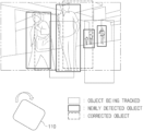
- FIG. 5 is a drawing illustrating an example of an object tracking process according to embodiments of the present disclosure.
- the Kalman filter may represent a state of each object as mean and variance.
- the object tracking process using the Kalman filter may be implemented with a prediction step, a matching step, an update step, and an initialization and termination step.
- an object state (a state mean and a state variance) on a new frame may be predicted based on motion information.
- a processor 150 of FIG. 1 may predict a state mean of the object at time t based on a measurement value at time t ⁇ 1.
- the processor 150 may correct the predicted state mean using a first correction algorithm or a second correction algorithm and may output the corrected state mean.
- the processor 150 may predict (estimate) a state variance at time t based on a measurement value at time t ⁇ 1.
- the processor 150 may calculate intersection over union (IoU) or Euclidean distance between the detected objects and objects being tracked and may perform matching between two objects using a Hungarian algorithm or a greedy algorithm based on the calculated value.
- IOU intersection over union
- Euclidean distance between the detected objects and objects being tracked
- a difference between the predicted object state and the matched object state may be calculated.
- the processor 150 may reflect the calculated difference and a Kalman gain in the predicted state mean at time t to update the state mean at time t. Furthermore, the processor 150 may update the state variance at time t.
- the detected object is initialized to a new object and tracking of the object being tracked may be ended.
- FIG. 6 is a flowchart illustrating a method for tracking an object in an electronic device according to embodiments of the present disclosure.
- a processor 150 of FIG. 1 may obtain sensing information.
- the sensing information may include an image, depth information, and/or rotation information.
- the processor 150 may obtain (acquire) an image and depth information from a camera 110 of FIG. 1 .
- the processor 150 may obtain rotation information of the camera 110 from a detector 120 of FIG. 1 .
- the processor 150 may identify whether there is an object (a first object) being tracked.
- the processor 150 may perform an operation after S 120 , when there is the object being tracked, and may perform an operation before S 160 , when there is no object being tracked.
- the processor 150 may identify whether the object being tracked has a class with high noise.
- the processor 150 may identify whether the object being tracked has the class with the high noise with reference to a lookup table stored in a memory 130 of FIG. 1 .
- the processor 150 may determine to apply a first correction algorithm.
- the first correction algorithm may correct state information of the object using a center position of an object bounding box bbox.
- the state information may include center coordinates, a width, and a height of the bounding box.
- the processor 150 may determine to apply a second correction algorithm.
- the processor 150 may determine to apply the second correction algorithm.
- the second correction algorithm may correct state information of the object using three points of the object bounding box bbox.
- the processor 150 may update (correct) state information of the object being tracked, using the determined correction algorithm.
- the processor 150 may attenuate an influence by camera rotation from previous state information of the object being tracked using rotation information.
- the processor 150 may detect an object (a second object) from the image obtained from the camera 110 .
- the processor 150 may detect a portion of the object being tracked and/or a new object.
- the processor 150 may detect all objects in the image as new objects.
- the processor 150 may identify whether there is depth information about the detected object.
- the processor 150 may estimate depth information.
- the processor 150 may calculate depth information of the object according to a size of the detected object bounding box based on prior information (e.g., an average size or the like).
- the processor 150 may track an object using an object tracking algorithm based on the depth information.
- the processor 150 may determine a change in state information of the detected object (the second object) matched with the object (the first object) being tracked based on the corrected state information of the object being tracked.
- the processor 150 may transmit the result of tracking the object to the outside.
- the processor 150 may transmit the result of tracking the object to an external system using a communicator 140 of FIG. 1 .
- the external system may provide a predetermined specific service using the result of tracking the object.
- FIG. 7 is a drawing illustrating a method for estimating depth information according to embodiments of the present disclosure.
- a depth of an object detected from an image may be calculated according to a size (a bbox size) of the object based on prior information about the object, for example, an average size of an adult face, an average height of an adult, and/or the like.
- FIGS. 8 A and 8 B are drawings illustrating a correction method with regard to linear motion of a camera according to another embodiment of the present disclosure.
- a camera 110 may have linear motion T R on x-, y-, and/or z-axis other than motion which rotates with respect to a specific axis.
- a processor 150 of FIG. 1 may obtain horizontal translation information together other than rotation information of the camera 110 using feature matching or an additional sensor.
- the processor 150 may reflect information T R about linear motion other than rotation information in Equation 3 above to represent it as Equation 10 below.
- P 3dnew R dif ⁇ 1 ⁇ ( P 3d +T R-cam ) ⁇ T R-cam +T R Equation 10:
- Correction for linear motion may be performed before or after a Kalman filter prediction step.
- a filter used for object tracking, matching metric (e.g., IoU, Euclidean distance, or the like), a data association algorithm (e.g., a Hungarian algorithm, a greedy algorithm, or the like) may be changed.
- an example of performing the motion modeling using the Kalman filter is described, but not limited thereto.
- An extended Kalman filter (EKF), a particle filter, a linear motion model, or the like may be used.
- FIG. 9 is a block diagram illustrating a computing system for executing a method tracking an object according to embodiments of the present disclosure.
- a computing system 1000 may include at least one processor 1100 , a memory 1300 , a user interface input device 1400 , a user interface output device 1500 , storage 1600 , and a network interface 1700 , which are connected with each other via a bus 1200 .
- the processor 1100 may be a central processing unit (CPU) or a semiconductor device that processes instructions stored in the memory 1300 and/or the storage 1600 .
- the memory 1300 and the storage 1600 may include various types of volatile or non-volatile storage media.
- the memory 1300 may include a read only memory (ROM) 1310 and a random access memory (RAM) 1320 .
- the operations of the method or the algorithm described in connection with the embodiments disclosed herein may be embodied directly in hardware or a software module executed by the processor 1100 , or in a combination thereof.
- the software module may reside on a storage medium (that is, the memory 1300 and/or the storage 1600 ) such as a RAM, a flash memory, a ROM, an EPROM, an EEPROM, a register, a hard disk, a removable disk, and a CD-ROM.
- the exemplary storage medium may be coupled to the processor 1100 .
- the processor 1100 may read out information from the storage medium and may write information in the storage medium.
- the storage medium may be integrated with the processor 1100 .
- the processor 1100 and the storage medium may reside in an application specific integrated circuit (ASIC).
- the ASIC may reside within a user terminal.
- the processor 1100 and the storage medium may reside in the user terminal as separate components.
- the electronic device may attenuate an influence according to rotation of the camera using rotation information of the camera and may accurately model only motion of the object, thus accurately tracking the object in a situation where the camera moves.
- the electronic device may quickly operate in an embedded environment, because computational burden is less than an existing technique such as feature matching.
- the electronic device may provide high correction reliability as a rotation error is not accumulated, because of using a rotation matrix difference value between two frames.
Landscapes
- Engineering & Computer Science (AREA)
- Physics & Mathematics (AREA)
- Theoretical Computer Science (AREA)
- General Physics & Mathematics (AREA)
- Computer Vision & Pattern Recognition (AREA)
- Multimedia (AREA)
- Artificial Intelligence (AREA)
- Health & Medical Sciences (AREA)
- Geometry (AREA)
- Computing Systems (AREA)
- Databases & Information Systems (AREA)
- Evolutionary Computation (AREA)
- General Health & Medical Sciences (AREA)
- Medical Informatics (AREA)
- Software Systems (AREA)
- Human Computer Interaction (AREA)
- Image Analysis (AREA)
Abstract
Description
R dif =R t ·R t-1 −1 Equation 1:
P 3d=depthold ·C −1 ·[x old y old,1]T Equation 2:
P 3dnew =R dif −1·(P 3d +T R-cam)−T R-cam Equation 3:
P 2dnew =C·(P 3dnew/depthnew) Equation 4:
p center=(p′ 1 +p 2′)/2 Equation 5:
w new =∥p′ 1 −p 3′∥2 Equation 6:
h new =∥p′ 2 −p 3′∥2 Equation 7:
P 3dnew =R dif −1·(P 3d +T R-cam)−T R-cam +T R Equation 10:
Claims (20)
Applications Claiming Priority (2)
| Application Number | Priority Date | Filing Date | Title |
|---|---|---|---|
| KR1020210102736A KR20230020845A (en) | 2021-08-04 | 2021-08-04 | Electronic deivce and method for tracking object thereof |
| KR10-2021-0102736 | 2021-08-04 |
Publications (2)
| Publication Number | Publication Date |
|---|---|
| US20230041382A1 US20230041382A1 (en) | 2023-02-09 |
| US12094134B2 true US12094134B2 (en) | 2024-09-17 |
Family
ID=85152627
Family Applications (1)
| Application Number | Title | Priority Date | Filing Date |
|---|---|---|---|
| US17/675,304 Active 2043-05-05 US12094134B2 (en) | 2021-08-04 | 2022-02-18 | Electronic device and method for tracking object thereof |
Country Status (2)
| Country | Link |
|---|---|
| US (1) | US12094134B2 (en) |
| KR (1) | KR20230020845A (en) |
Cited By (1)
| Publication number | Priority date | Publication date | Assignee | Title |
|---|---|---|---|---|
| US12260498B1 (en) * | 2023-12-13 | 2025-03-25 | Corners Co., Ltd. | Method and system for identifying and tracking an object in space and generating digital twin contents including a corresponding object with regard to the space |
Families Citing this family (4)
| Publication number | Priority date | Publication date | Assignee | Title |
|---|---|---|---|---|
| WO2020213099A1 (en) * | 2019-04-17 | 2020-10-22 | 日本電気株式会社 | Object detection/tracking device, method, and program recording medium |
| KR102585255B1 (en) * | 2023-04-26 | 2023-10-05 | 주식회사 케이유전자 | Multi-camera frame-to-frame matching and tracking algorithm based on Kalman filter |
| CN117036485A (en) * | 2023-08-25 | 2023-11-10 | 北京地平线信息技术有限公司 | Spatial information prediction method, device, readable storage medium and electronic equipment |
| CN117241133B (en) * | 2023-11-13 | 2024-02-06 | 武汉益模科技股份有限公司 | Visual work reporting method and system based on multi-process simultaneous operations in non-fixed positions |
Citations (16)
| Publication number | Priority date | Publication date | Assignee | Title |
|---|---|---|---|---|
| KR100343780B1 (en) | 2000-07-31 | 2002-07-20 | 한국전자통신연구원 | Method of Camera Motion Detection in Compressed Domain for Content-Based Indexing of Compressed Video |
| KR100544677B1 (en) | 2003-12-26 | 2006-01-23 | 한국전자통신연구원 | 3D object tracking device and method using multiview image and depth information |
| US20060238549A1 (en) * | 2000-07-21 | 2006-10-26 | Sony Computer Entertainment Inc. | System and method for object tracking |
| US20100208941A1 (en) | 2009-02-13 | 2010-08-19 | Broaddus Christopher P | Active coordinated tracking for multi-camera systems |
| KR101156547B1 (en) | 2010-12-30 | 2012-06-20 | 주식회사 나무가 | Face and Hand Navigation Using Algibi and Depth Images |
| US8379014B2 (en) | 2007-10-11 | 2013-02-19 | Mvtec Software Gmbh | System and method for 3D object recognition |
| KR101275297B1 (en) | 2011-06-23 | 2013-06-17 | 주식회사 삼성항공정보통신 | Camera Apparatus of tracking moving object |
| KR101364046B1 (en) | 2012-11-05 | 2014-02-19 | 재단법인대구경북과학기술원 | Method and apparatus for object tracking in video sequences |
| US9277122B1 (en) | 2015-08-13 | 2016-03-01 | Legend3D, Inc. | System and method for removing camera rotation from a panoramic video |
| KR20180046543A (en) | 2016-10-28 | 2018-05-09 | 삼성전자주식회사 | Electronic device and method for acquiring omnidirectional image |
| KR20190069957A (en) | 2017-12-12 | 2019-06-20 | 연세대학교 산학협력단 | Method for Real-time Odometry Estimation using Mono camera and IMU sensor |
| US10567657B2 (en) | 2016-03-30 | 2020-02-18 | Shanghai Bizhi Bionic Technology Co., Ltd | Image processing method and system for vision system |
| KR20200044182A (en) | 2018-10-05 | 2020-04-29 | 삼성전자주식회사 | Method for recognizing object and autonomous driving device therefor |
| KR102121287B1 (en) | 2013-07-17 | 2020-06-10 | 엘지이노텍 주식회사 | Camera system and controlling method of Camera system |
| US20200342613A1 (en) * | 2019-04-22 | 2020-10-29 | Ooo Itv Group | System and Method for Tracking Moving Objects |
| EP3796131A1 (en) * | 2018-05-29 | 2021-03-24 | Samsung Electronics Co., Ltd. | Electronic device and method for displaying object associated with external electronic device on basis of position and movement of external electronic device |
-
2021
- 2021-08-04 KR KR1020210102736A patent/KR20230020845A/en active Pending
-
2022
- 2022-02-18 US US17/675,304 patent/US12094134B2/en active Active
Patent Citations (19)
| Publication number | Priority date | Publication date | Assignee | Title |
|---|---|---|---|---|
| US20060238549A1 (en) * | 2000-07-21 | 2006-10-26 | Sony Computer Entertainment Inc. | System and method for object tracking |
| KR100343780B1 (en) | 2000-07-31 | 2002-07-20 | 한국전자통신연구원 | Method of Camera Motion Detection in Compressed Domain for Content-Based Indexing of Compressed Video |
| KR100544677B1 (en) | 2003-12-26 | 2006-01-23 | 한국전자통신연구원 | 3D object tracking device and method using multiview image and depth information |
| US8379014B2 (en) | 2007-10-11 | 2013-02-19 | Mvtec Software Gmbh | System and method for 3D object recognition |
| US20100208941A1 (en) | 2009-02-13 | 2010-08-19 | Broaddus Christopher P | Active coordinated tracking for multi-camera systems |
| KR101156547B1 (en) | 2010-12-30 | 2012-06-20 | 주식회사 나무가 | Face and Hand Navigation Using Algibi and Depth Images |
| KR101275297B1 (en) | 2011-06-23 | 2013-06-17 | 주식회사 삼성항공정보통신 | Camera Apparatus of tracking moving object |
| KR101364046B1 (en) | 2012-11-05 | 2014-02-19 | 재단법인대구경북과학기술원 | Method and apparatus for object tracking in video sequences |
| KR102121287B1 (en) | 2013-07-17 | 2020-06-10 | 엘지이노텍 주식회사 | Camera system and controlling method of Camera system |
| US9277122B1 (en) | 2015-08-13 | 2016-03-01 | Legend3D, Inc. | System and method for removing camera rotation from a panoramic video |
| US10567657B2 (en) | 2016-03-30 | 2020-02-18 | Shanghai Bizhi Bionic Technology Co., Ltd | Image processing method and system for vision system |
| US20190342501A1 (en) | 2016-10-28 | 2019-11-07 | Samsung Electronics Co., Ltd | Method and apparatus for acquiring omnidirectional video |
| KR20180046543A (en) | 2016-10-28 | 2018-05-09 | 삼성전자주식회사 | Electronic device and method for acquiring omnidirectional image |
| US11006048B2 (en) | 2016-10-28 | 2021-05-11 | Samsung Electronics Co., Ltd. | Method and apparatus for acquiring omnidirectional video |
| KR20190069957A (en) | 2017-12-12 | 2019-06-20 | 연세대학교 산학협력단 | Method for Real-time Odometry Estimation using Mono camera and IMU sensor |
| EP3796131A1 (en) * | 2018-05-29 | 2021-03-24 | Samsung Electronics Co., Ltd. | Electronic device and method for displaying object associated with external electronic device on basis of position and movement of external electronic device |
| KR20200044182A (en) | 2018-10-05 | 2020-04-29 | 삼성전자주식회사 | Method for recognizing object and autonomous driving device therefor |
| US20210350145A1 (en) | 2018-10-05 | 2021-11-11 | Samsung Electronics Co., Ltd. | Object recognition method of autonomous driving device, and autonomous driving device |
| US20200342613A1 (en) * | 2019-04-22 | 2020-10-29 | Ooo Itv Group | System and Method for Tracking Moving Objects |
Non-Patent Citations (3)
| Title |
|---|
| Davison et al., "MonoSLAM: Real-Time Single Camera SLAM," in IEEE Transactions on Pattern Analysis and Machine Intelligence, vol. 29, No. 6, pp. 1052-1067, Jun. 2007, doi:10.1109/TPAMI.2007.1049. |
| Yoon et al., "Bayesian Multi-object Tracking Using Motion Context from Multiple Objects. Proceedings"—2015 IEEE Winter Conference on Applications of Computer Vision, WACV 2015. 33-40. 10.1109/WACV.2015.12. |
| Yoon et al., "Online Multi-object Tracking via Structural Constraint Event Aggregation" 1392-1400. 10.1109/CVPR.2016.155. |
Cited By (1)
| Publication number | Priority date | Publication date | Assignee | Title |
|---|---|---|---|---|
| US12260498B1 (en) * | 2023-12-13 | 2025-03-25 | Corners Co., Ltd. | Method and system for identifying and tracking an object in space and generating digital twin contents including a corresponding object with regard to the space |
Also Published As
| Publication number | Publication date |
|---|---|
| KR20230020845A (en) | 2023-02-13 |
| US20230041382A1 (en) | 2023-02-09 |
Similar Documents
| Publication | Publication Date | Title |
|---|---|---|
| US12094134B2 (en) | Electronic device and method for tracking object thereof | |
| CN107016705B (en) | Ground plane estimation in computer vision systems | |
| CN111442722B (en) | Positioning method, device, storage medium and electronic device | |
| US9013617B2 (en) | Gyroscope conditioning and gyro-camera alignment | |
| US10789719B2 (en) | Method and apparatus for detection of false alarm obstacle | |
| CN111684382B (en) | Method and system for estimating state of mobile platform, mobile platform and storage medium | |
| KR101985344B1 (en) | Sliding windows based structure-less localization method using inertial and single optical sensor, recording medium and device for performing the method | |
| EP2901236B1 (en) | Video-assisted target location | |
| US11228654B2 (en) | Tracking device, tracking method, and tracking system | |
| US11704815B2 (en) | Tracking device, tracking method, and tracking system | |
| TW202229818A (en) | Lane mapping and localization using periodically-updated anchor frames | |
| Nobre et al. | Drift-correcting self-calibration for visual-inertial SLAM | |
| CN111955005B (en) | Method and system for processing 360-degree image content | |
| CN111882494B (en) | Pose graph processing method and device, computer equipment and storage medium | |
| US20210004978A1 (en) | Method for acquiring depth information of target object and movable platform | |
| CN113126117B (en) | Method for determining absolute scale of SFM map and electronic equipment | |
| US20230091546A1 (en) | Head posture estimation device and head posture estimation method | |
| CN113034538B (en) | Pose Tracking Method and Device for Visual Inertial Navigation Equipment, and Visual Inertial Navigation Equipment | |
| CN115128655B (en) | Positioning method and device for automatic driving vehicle, electronic equipment and storage medium | |
| CN115077467B (en) | Cleaning robot posture estimation method and device and cleaning robot | |
| JP7185786B2 (en) | Positioning system and terminal | |
| CN114894222A (en) | External parameter calibration method of IMU-GNSS antenna and related method and equipment | |
| US20250061706A1 (en) | Image processing method and system for identifying a feature within a scene | |
| EP4345750A1 (en) | Position estimation system, position estimation method, and program | |
| US20240337747A1 (en) | Sensor apparatus with multiple sensors for moving agent |
Legal Events
| Date | Code | Title | Description |
|---|---|---|---|
| AS | Assignment |
Owner name: KIA CORPORATION, KOREA, REPUBLIC OF Free format text: ASSIGNMENT OF ASSIGNORS INTEREST;ASSIGNOR:YOON, YOUNG CHUL;REEL/FRAME:059048/0230 Effective date: 20211217 Owner name: HYUNDAI MOTOR COMPANY, KOREA, REPUBLIC OF Free format text: ASSIGNMENT OF ASSIGNORS INTEREST;ASSIGNOR:YOON, YOUNG CHUL;REEL/FRAME:059048/0230 Effective date: 20211217 |
|
| FEPP | Fee payment procedure |
Free format text: ENTITY STATUS SET TO UNDISCOUNTED (ORIGINAL EVENT CODE: BIG.); ENTITY STATUS OF PATENT OWNER: LARGE ENTITY |
|
| STPP | Information on status: patent application and granting procedure in general |
Free format text: DOCKETED NEW CASE - READY FOR EXAMINATION |
|
| STPP | Information on status: patent application and granting procedure in general |
Free format text: NOTICE OF ALLOWANCE MAILED -- APPLICATION RECEIVED IN OFFICE OF PUBLICATIONS |
|
| ZAAB | Notice of allowance mailed |
Free format text: ORIGINAL CODE: MN/=. |
|
| STPP | Information on status: patent application and granting procedure in general |
Free format text: PUBLICATIONS -- ISSUE FEE PAYMENT RECEIVED |
|
| STPP | Information on status: patent application and granting procedure in general |
Free format text: PUBLICATIONS -- ISSUE FEE PAYMENT VERIFIED |
|
| STCF | Information on status: patent grant |
Free format text: PATENTED CASE |