US12088383B2 - Uplink SRS with precoding - Google Patents
Uplink SRS with precoding Download PDFInfo
- Publication number
- US12088383B2 US12088383B2 US17/276,765 US201817276765A US12088383B2 US 12088383 B2 US12088383 B2 US 12088383B2 US 201817276765 A US201817276765 A US 201817276765A US 12088383 B2 US12088383 B2 US 12088383B2
- Authority
- US
- United States
- Prior art keywords
- srs
- precoders
- resources
- ports
- srs resources
- Prior art date
- Legal status (The legal status is an assumption and is not a legal conclusion. Google has not performed a legal analysis and makes no representation as to the accuracy of the status listed.)
- Active, expires
Links
Images


Classifications
-
- H—ELECTRICITY
- H04—ELECTRIC COMMUNICATION TECHNIQUE
- H04L—TRANSMISSION OF DIGITAL INFORMATION, e.g. TELEGRAPHIC COMMUNICATION
- H04L5/00—Arrangements affording multiple use of the transmission path
- H04L5/003—Arrangements for allocating sub-channels of the transmission path
- H04L5/0048—Allocation of pilot signals, i.e. of signals known to the receiver
-
- H—ELECTRICITY
- H04—ELECTRIC COMMUNICATION TECHNIQUE
- H04B—TRANSMISSION
- H04B7/00—Radio transmission systems, i.e. using radiation field
- H04B7/02—Diversity systems; Multi-antenna system, i.e. transmission or reception using multiple antennas
- H04B7/04—Diversity systems; Multi-antenna system, i.e. transmission or reception using multiple antennas using two or more spaced independent antennas
- H04B7/06—Diversity systems; Multi-antenna system, i.e. transmission or reception using multiple antennas using two or more spaced independent antennas at the transmitting station
- H04B7/0613—Diversity systems; Multi-antenna system, i.e. transmission or reception using multiple antennas using two or more spaced independent antennas at the transmitting station using simultaneous transmission
- H04B7/0615—Diversity systems; Multi-antenna system, i.e. transmission or reception using multiple antennas using two or more spaced independent antennas at the transmitting station using simultaneous transmission of weighted versions of same signal
- H04B7/0619—Diversity systems; Multi-antenna system, i.e. transmission or reception using multiple antennas using two or more spaced independent antennas at the transmitting station using simultaneous transmission of weighted versions of same signal using feedback from receiving side
- H04B7/0636—Feedback format
- H04B7/0639—Using selective indices, e.g. of a codebook, e.g. pre-distortion matrix index [PMI] or for beam selection
-
- H—ELECTRICITY
- H04—ELECTRIC COMMUNICATION TECHNIQUE
- H04B—TRANSMISSION
- H04B7/00—Radio transmission systems, i.e. using radiation field
- H04B7/02—Diversity systems; Multi-antenna system, i.e. transmission or reception using multiple antennas
- H04B7/04—Diversity systems; Multi-antenna system, i.e. transmission or reception using multiple antennas using two or more spaced independent antennas
- H04B7/0404—Diversity systems; Multi-antenna system, i.e. transmission or reception using multiple antennas using two or more spaced independent antennas the mobile station comprising multiple antennas, e.g. to provide uplink diversity
-
- H—ELECTRICITY
- H04—ELECTRIC COMMUNICATION TECHNIQUE
- H04B—TRANSMISSION
- H04B7/00—Radio transmission systems, i.e. using radiation field
- H04B7/02—Diversity systems; Multi-antenna system, i.e. transmission or reception using multiple antennas
- H04B7/04—Diversity systems; Multi-antenna system, i.e. transmission or reception using multiple antennas using two or more spaced independent antennas
- H04B7/0413—MIMO systems
- H04B7/0456—Selection of precoding matrices or codebooks, e.g. using matrices antenna weighting
-
- H—ELECTRICITY
- H04—ELECTRIC COMMUNICATION TECHNIQUE
- H04L—TRANSMISSION OF DIGITAL INFORMATION, e.g. TELEGRAPHIC COMMUNICATION
- H04L25/00—Baseband systems
- H04L25/02—Details ; arrangements for supplying electrical power along data transmission lines
- H04L25/0202—Channel estimation
- H04L25/0224—Channel estimation using sounding signals
- H04L25/0226—Channel estimation using sounding signals sounding signals per se
-
- H—ELECTRICITY
- H04—ELECTRIC COMMUNICATION TECHNIQUE
- H04L—TRANSMISSION OF DIGITAL INFORMATION, e.g. TELEGRAPHIC COMMUNICATION
- H04L5/00—Arrangements affording multiple use of the transmission path
- H04L5/003—Arrangements for allocating sub-channels of the transmission path
- H04L5/0048—Allocation of pilot signals, i.e. of signals known to the receiver
- H04L5/0051—Allocation of pilot signals, i.e. of signals known to the receiver of dedicated pilots, i.e. pilots destined for a single user or terminal
-
- H—ELECTRICITY
- H04—ELECTRIC COMMUNICATION TECHNIQUE
- H04L—TRANSMISSION OF DIGITAL INFORMATION, e.g. TELEGRAPHIC COMMUNICATION
- H04L5/00—Arrangements affording multiple use of the transmission path
- H04L5/003—Arrangements for allocating sub-channels of the transmission path
- H04L5/0048—Allocation of pilot signals, i.e. of signals known to the receiver
- H04L5/005—Allocation of pilot signals, i.e. of signals known to the receiver of common pilots, i.e. pilots destined for multiple users or terminals
Definitions
- aspects of the present disclosure relate to wireless communications, and more particularly, to techniques for providing precoders for uplink sound reference signals (SRS).
- SRS uplink sound reference signals
- Wireless communication systems are widely deployed to provide various telecommunication services such as telephony, video, data, messaging, broadcasts, etc. These wireless communication systems may employ multiple-access technologies capable of supporting communication with multiple users by sharing available system resources (e.g., bandwidth, transmit power, etc.). Examples of such multiple-access systems include 3rd Generation Partnership Project (3GPP) Long Term Evolution (LTE) systems, LTE Advanced (LTE-A) systems, code division multiple access (CDMA) systems, time division multiple access (TDMA) systems, frequency division multiple access (FDMA) systems, orthogonal frequency division multiple access (OFDMA) systems, single-carrier frequency division multiple access (SC-FDMA) systems, and time division synchronous code division multiple access (TD-SCDMA) systems, to name a few.
- 3GPP 3rd Generation Partnership Project
- LTE Long Term Evolution
- LTE-A LTE Advanced
- CDMA code division multiple access
- TDMA time division multiple access
- FDMA frequency division multiple access
- OFDMA orthogonal frequency division
- a wireless multiple-access communication system may include a number of base stations (BSs), which are each capable of simultaneously supporting communication for multiple communication devices, otherwise known as user equipments (UEs).
- BSs base stations
- UEs user equipments
- a set of one or more base stations may define an eNodeB (eNB).
- eNB eNodeB
- a wireless multiple access communication system may include a number of distributed units (DUs) (e.g., edge units (EUs), edge nodes (ENs), radio heads (RHs), smart radio heads (SRHs), transmission reception points (TRPs), etc.) in communication with a number of central units (CUs) (e.g., central nodes (CNs), access node controllers (ANCs), etc.), where a set of one or more DUs, in communication with a CU, may define an access node (e.g., which may be referred to as a BS, 5G NB, next generation NodeB (gNB or gNodeB), transmission reception point (TRP), etc.).
- DUs distributed units
- EUs edge units
- ENs edge nodes
- RHs radio heads
- RHs smart radio heads
- TRPs transmission reception points
- CUs central units
- CUs central nodes
- ANCs access node controllers
- a BS or DU may communicate with a set of UEs on downlink channels (e.g., for transmissions from a BS or DU to a UE) and uplink channels (e.g., for transmissions from a UE to BS or DU).
- downlink channels e.g., for transmissions from a BS or DU to a UE
- uplink channels e.g., for transmissions from a UE to BS or DU.
- NR new radio or 5G
- LTE long term evolution
- NR is a set of enhancements to the LTE mobile standard promulgated by 3GPP.
- NR is designed to better support mobile broadband Internet access by improving spectral efficiency, lowering costs, improving services, making use of new spectrum, and better integrating with other open standards using OFDMA with a cyclic prefix (CP) on the downlink (DL) and on the uplink (UL).
- CP cyclic prefix
- NR supports beamforming, multiple-input multiple-output (MIMO) antenna technology, and carrier aggregation.
- MIMO multiple-input multiple-output
- Certain aspects provide a method for wireless communication by a base station (BS).
- the method generally includes configuring a user equipment (UE) with a sounding reference signal (SRS) configuration that configures one or more SRS resource sets, each resource set including one or more SRS resources, each SRS resource comprising one or more SRS ports.
- the method generally includes providing the UE with a set of precoders via an indicator, the set of precoders including a precoder associated with each SRS resource.
- UE user equipment
- SRS sounding reference signal
- the method generally includes receiving a SRS configuration that configures one or more SRS resource sets, each resource set including one or more SRS resources, each SRS resource comprising one or more SRS ports.
- the method generally includes receiving a set of precoders via an indicator, the set of precoders including a precoder associated with each SRS resource and determining one or more precoders to apply for one or more SRS transmissions via one or more of the SRS resources.
- the apparatus generally includes means for configuring a UE with a SRS configuration that configures one or more SRS resource sets, each resource set including one or more SRS resources, each SRS resource comprising one or more SRS ports.
- the apparatus generally includes means for providing the UE with a set of precoders via an indicator, the set of precoders including a precoder associated with each SRS resource.
- the apparatus generally includes means for receiving a SRS configuration that configures one or more SRS resource sets, each resource set including one or more SRS resources, each SRS resource comprising one or more SRS ports.
- the apparatus generally includes means for receiving a set of precoders via an indicator, the set of precoders including a precoder associated with each SRS resource and means for determining one or more precoders to apply for one or more SRS transmissions via one or more of the SRS resources.
- the apparatus generally includes at least one processor coupled with a memory and configured to configure a UE with a SRS configuration that configures one or more SRS resource sets, each resource set including one or more SRS resources, each SRS resource comprising one or more SRS ports.
- the at least one processor is configured to provide the UE with a set of precoders via an indicator, the set of precoders including a precoder associated with each SRS resource.
- the apparatus generally includes a receiver configured to receive a SRS configuration that configures one or more SRS resource sets, each resource set including one or more SRS resources, each SRS resource comprising one or more SRS ports.
- the receiver is configured to receive a set of precoders via an indicator, the set of precoders including a precoder associated with each SRS resource.
- the apparatus generally includes at least one processor coupled with a memory and configured to determine one or more precoders to apply for one or more SRS transmissions via one or more of the SRS resources.
- the computer executable code generally includes code for configuring a UE with a SRS configuration that configures one or more SRS resource sets, each resource set including one or more SRS resources, each SRS resource comprising one or more SRS ports.
- the computer executable code generally includes code for providing the UE with a set of precoders via an indicator, the set of precoders including a precoder associated with each SRS resource.
- the computer executable code generally includes code for receiving a SRS configuration that configures one or more SRS resource sets, each resource set including one or more SRS resources, each SRS resource comprising one or more SRS ports.
- the computer executable code generally includes code for receiving a set of precoders via an indicator, the set of precoders including a precoder associated with each SRS resource and code for determining one or more precoders to apply for one or more SRS transmissions via one or more of the SRS resources.
- the one or more aspects comprise the features hereinafter fully described and particularly pointed out in the claims.
- the following description and the appended drawings set forth in detail certain illustrative features of the one or more aspects. These features are indicative, however, of but a few of the various ways in which the principles of various aspects may be employed.
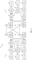
- FIG. 1 is a block diagram conceptually illustrating an example telecommunications system, in accordance with certain aspects of the present disclosure.
- FIG. 2 is a block diagram illustrating an example logical architecture of a distributed radio access network (RAN), in accordance with certain aspects of the present disclosure.
- RAN radio access network
- FIG. 3 is a diagram illustrating an example physical architecture of a distributed RAN, in accordance with certain aspects of the present disclosure.
- FIG. 4 is a block diagram conceptually illustrating a design of an example base station (BS) and user equipment (UE), in accordance with certain aspects of the present disclosure.
- BS base station
- UE user equipment
- FIG. 5 is a diagram showing examples for implementing a communication protocol stack, in accordance with certain aspects of the present disclosure.
- FIG. 6 illustrates an example of a frame format for a new radio (NR) system, in accordance with certain aspects of the present disclosure.
- NR new radio
- FIG. 7 A is a block diagram showing example mapping of UE ports for a UE with four antennas and four receive chains, in accordance with certain aspects of the present disclosure.
- FIG. 7 B is a block diagram showing an example mapping of sounding reference signal (SRS) ports to UE ports for a UE with four antennas and two transmit chains for a first configured SRS resource, in accordance with certain aspects of the present disclosure.
- SRS sounding reference signal
- FIG. 7 C is a block diagram showing an example mapping of SRS ports to UE ports for a UE with four antennas and two transmit chains for a second configured SRS resource, in accordance with certain aspects of the present disclosure.
- FIG. 8 A is a block diagram showing example mapping of UE ports for a UE with four antennas with beamforming and four receive chains, in accordance with certain aspects of the present disclosure.
- FIG. 8 B is a block diagram showing an example mapping of SRS ports to UE ports for a UE with four antennas with beamforming and two transmit chains for a first configured SRS resource, in accordance with certain aspects of the present disclosure.
- FIG. 8 C is a block diagram showing an example mapping of SRS ports to UE ports for a UE with four antennas with beamforming and two transmit chains for a second configured SRS resource, in accordance with certain aspects of the present disclosure.
- FIG. 10 is a flow diagram illustrating example operations for wireless communication by a UE, in accordance with certain aspects of the present disclosure.
- FIG. 11 A is a block diagram showing an example mapping of SRS ports to UE ports for a UE with four antennas and two transmit chains for a first configured SRS resource using a precoder, in accordance with certain aspects of the present disclosure.
- FIG. 11 B is a block diagram showing an example mapping of SRS ports to UE ports for a UE with four antennas and two transmit chains for a second configured SRS resource using a precoder, in accordance with certain aspects of the present disclosure.
- FIG. 12 A is a block diagram showing an example mapping of SRS ports to UE ports for a UE with four antennas with beamforming and two transmit chains for a first configured SRS resource using a precoder, in accordance with certain aspects of the present disclosure.
- FIG. 12 B is a block diagram showing an example mapping of SRS ports to UE ports for a UE with four antennas with beamforming and two transmit chains for a second configured SRS resource using a precoder, in accordance with certain aspects of the present disclosure.
- FIG. 13 illustrates a communications device that may include various components configured to perform operations for the techniques disclosed herein in accordance with aspects of the present disclosure.
- FIG. 14 illustrates a communications device that may include various components configured to perform operations for the techniques disclosed herein in accordance with aspects of the present disclosure.
- FIGS. 15 - 21 illustrate example transmission precoding matrix indicators (TPMI) used for PUSCH, in accordance with certain aspects of the present disclosure.
- TPMI transmission precoding matrix indicators
- aspects of the present disclosure provide apparatus, methods, processing systems, and computer readable mediums for providing precoders for uplink sound reference signals (SRS) transmissions.
- SRS uplink sound reference signals
- the uplink SRS may be used for beam management, codebook based uplink transmission, and/or non-codebook based uplink transmission.
- the downlink SRS may be used for antenna switching and/or channel reciprocity for the base station (BS) to obtain the downlink channel.
- the UE may have asymmetry of its transmit and receive chains. For example, the UE may have less transmit chains than receive chains.
- the UE may perform SRS antenna switching to make use of all of the antennas.
- the BS can configure the UE with two SRS resources, each using different antennas. The UE can switch between the SRS resources for SRS transmission in different symbols.
- the sounding quality could be poor. Therefore, techniques for SRS transmission with improved sounding quality are desirable.
- aspects of the present disclosure provide for SRS precoding that may be used to improve the sounding quality.
- the BS provides the UE with precoders associated with the configured SRS resources.
- the UE may apply the precoders for SRS transmission.
- a CDMA network may implement a radio technology such as Universal Terrestrial Radio Access (UTRA), cdma2000, etc.
- UTRA includes Wideband CDMA (WCDMA) and other variants of CDMA.
- cdma2000 covers IS-2000, IS-95 and IS-856 standards.
- a TDMA network may implement a radio technology such as Global System for Mobile Communications (GSM).
- GSM Global System for Mobile Communications
- An OFDMA network may implement a radio technology such as NR (e.g.
- E-UTRA Evolved UTRA
- UMB Ultra Mobile Broadband
- IEEE 802.11 Wi-Fi
- IEEE 802.16 WiMAX
- IEEE 802.20 Flash-OFDMA, etc.
- UTRA and E-UTRA are part of Universal Mobile Telecommunication System (UMTS).
- New Radio is an emerging wireless communications technology under development in conjunction with the 5G Technology Forum (5GTF), 3GPP Long Term Evolution (LTE) and LTE-Advanced (LTE-A) are releases of UMTS that use E-UTRA.
- LTE, LTE-A and GSM are described in documents from an organization named “3rd Generation Partnership Project” (3GPP).
- cdma2000 and UMB are described in documents from an organization named “3rd Generation Partnership Project 2” (3GPP2).
- the techniques described herein may be used for the wireless networks and radio technologies mentioned above as well as other wireless networks and radio technologies.
- aspects may be described herein using terminology commonly associated with 3G and/or 4G wireless technologies, aspects of the present disclosure can be applied in other generation-based communication systems, such as 5G and later, including NR technologies.
- New radio (NR) access may support various wireless communication services, such as enhanced mobile broadband (eMBB) targeting wide bandwidth (e.g., 80 MHz or beyond), millimeter wave (mmW) targeting high carrier frequency (e.g., 25 GHz or beyond), massive machine type communications MTC (mMTC) targeting non-backward compatible MTC techniques, and/or mission critical targeting ultra-reliable low-latency communications (URLLC).
- eMBB enhanced mobile broadband
- mmW millimeter wave
- mMTC massive machine type communications MTC
- URLLC ultra-reliable low-latency communications
- These services may include latency and reliability requirements.
- These services may also have different transmission time intervals (TTI) to meet respective quality of service (QoS) requirements.
- TTI transmission time intervals
- QoS quality of service
- these services may co-exist in the same subframe.
- FIG. 1 illustrates an example wireless communication network 100 in which aspects of the present disclosure may be performed.
- the wireless communication network 100 may be a New Radio (NR) or 5G network.
- a BS 110 in the wireless communication network 100 configures a UE 120 with a sounding reference signal (SRS) configuration.
- the SRS configuration configures one or more SRS resource sets, each resource set including one or more SRS resources, and each SRS resource comprising one or more SRS ports.
- the BS 110 provides the UE 120 with a set of precoders via an indicator, the set of precoders including a precoder associated with each SRS resource.
- the UE 120 determines one or more precoders to apply for one or more SRS transmissions via one or more of the configured SRS resources.
- the wireless communication network 100 may include a number of base stations (BSs) 110 and other network entities.
- a BS may be a station that communicates with user equipments (UEs).
- Each BS 110 may provide communication coverage for a particular geographic area.
- the term “cell” can refer to a coverage area of a Node B (NB) and/or a NB subsystem serving this coverage area, depending on the context in which the term is used.
- NB Node B
- AP access point
- TRP transmission reception point
- a cell may not necessarily be stationary, and the geographic area of the cell may move according to the location of a mobile BS.
- the base stations may be interconnected to one another and/or to one or more other base stations or network nodes (not shown) in wireless communication network 100 through various types of backhaul interfaces, such as a direct physical connection, a wireless connection, a virtual network, or the like using any suitable transport network.
- any number of wireless networks may be deployed in a given geographic area.
- Each wireless network may support a particular radio access technology (RAT) and may operate on one or more frequencies.
- a RAT may also be referred to as a radio technology, an air interface, etc.
- a frequency may also be referred to as a carrier, a subcarrier, a frequency channel, a tone, a subband, etc.
- Each frequency may support a single RAT in a given geographic area in order to avoid interference between wireless networks of different RATs.
- NR or 5G RAT networks may be deployed.
- a BS may provide communication coverage for a macro cell, a pico cell, a femto cell, and/or other types of cells.
- a macro cell may cover a relatively large geographic area (e.g., several kilometers in radius) and may allow unrestricted access by UEs with service subscription.
- a pico cell may cover a relatively small geographic area and may allow unrestricted access by UEs with service subscription.
- a femto cell may cover a relatively small geographic area (e.g., a home) and may allow restricted access by UEs having an association with the femto cell (e.g., UEs in a Closed Subscriber Group (CSG). UEs for users in the home, etc.).
- CSG Closed Subscriber Group
- a BS for a macro cell may be referred to as a macro BS.
- a BS for a pico cell may be referred to as a pico BS.
- a BS for a femto cell may be referred to as a femto BS or a home BS.
- the BSs 110 a , 110 b and 110 c may be macro BSs for the macro cells 102 a . 102 b and 102 c , respectively.
- the BS 110 x may be a pico BS for a pico cell 102 x .
- the BSs 110 y and 110 z may be femto BSs for the femto cells 102 y and 102 z , respectively.
- a BS may support one or multiple (e.g., three) cells.
- Wireless communication network 100 may also include relay stations.
- a relay station is a station that receives a transmission of data and/or other information from an upstream station (e.g., a BS or a UE) and sends a transmission of the data and/or other information to a downstream station (e.g., a UE or a BS).
- a relay station may also be a UE that relays transmissions for other UEs.
- a relay station 110 r may communicate with the BS 110 a and a UE 120 r in order to facilitate communication between the BS 110 a and the UE 120 r .
- a relay station may also be referred to as a relay BS, a relay, etc.
- Wireless communication network 100 may be a heterogeneous network that includes BSs of different types, e.g., macro BS, pico BS, femto BS, relays, etc. These different types of BSs may have different transmit power levels, different coverage areas, and different impact on interference in the wireless communication network 100 .
- macro BS may have a high transmit power level (e.g., 20 Watts) whereas pico BS, femto BS, and relays may have a lower transmit power level (e.g., 1 Watt).
- Wireless communication network 100 may support synchronous or asynchronous operation.
- the BSs may have similar frame timing, and transmissions from different BSs may be approximately aligned in time.
- the BSs may have different frame timing, and transmissions from different BSs may not be aligned in time.
- the techniques described herein may be used for both synchronous and asynchronous operation.
- a network controller 130 may couple to a set of BSs and provide coordination and control for these BSs.
- the network controller 130 may communicate with the BSs 110 via a backhaul.
- the BSs 110 may also communicate with one another (e.g., directly or indirectly) via wireless or wireline backhaul.
- the UEs 120 may be dispersed throughout the wireless communication network 100 , and each UE may be stationary or mobile.
- a UE may also be referred to as a mobile station, a terminal, an access terminal, a subscriber unit, a station, a Customer Premises Equipment (CPE), a cellular phone, a smart phone, a personal digital assistant (PDA), a wireless modem, a wireless communication device, a handheld device, a laptop computer, a cordless phone, a wireless local loop (WLL) station, a tablet computer, a camera, a gaming device, a netbook, a smartbook, an ultrabook, an appliance, a medical device or medical equipment, a biometric sensor/device, a wearable device such as a smart watch, smart clothing, smart glasses, a smart wrist band, smart jewelry (e.g., a smart ring, a smart bracelet, etc.), an entertainment device (e.g., a
- MTC and eMTC UEs include, for example, robots, drones, remote devices, sensors, meters, monitors, location tags, etc., that may communicate with a BS, another device (e.g., remote device), or some other entity.
- a wireless node may provide, for example, connectivity for or to a network (e.g., a wide area network such as Internet or a cellular network) via a wired or wireless communication link.
- Some UEs may be considered Internet-of-Things (IoT) devices, which may be narrowband IoT (NB-IoT) devices.
- IoT Internet-of-Things
- NB-IoT narrowband IoT
- Certain wireless networks utilize orthogonal frequency division multiplexing (OFDM) on the downlink and single-carrier frequency division multiplexing (SC-FDM) on the uplink.
- OFDM and SC-FDM partition the system bandwidth into multiple (K) orthogonal subcarriers, which are also commonly referred to as tones, bins, etc.
- K orthogonal subcarriers
- Each subcarrier may be modulated with data.
- modulation symbols are sent in the frequency domain with OFDM and in the time domain with SC-FDM.
- the spacing between adjacent subcarriers may be fixed, and the total number of subcarriers (K) may be dependent on the system bandwidth.
- the spacing of the subcarriers may be 15 kHz and the minimum resource allocation (called a “resource block” (RB)) may be 12 subcarriers (or 180 kHz). Consequently, the nominal Fast Fourier Transfer (FFT) size may be equal to 128, 256, 512, 1024 or 2048 for system bandwidth of 1.25, 2.5, 5, 10, or 20 megahertz (MHz), respectively.
- the system bandwidth may also be partitioned into subbands. For example, a subband may cover 1.08 MHz (i.e., 6 resource blocks), and there may be 1, 2, 4, 8, or 16 subbands for system bandwidth of 1.25, 2.5, 5, 10 or 20 MHz, respectively.
- NR may utilize OFDM with a CP on the uplink and downlink and include support for half-duplex operation using TDD. Beamforming may be supported and beam direction may be dynamically configured. MIMO transmissions with precoding may also be supported. MIMO configurations in the DL may support up to 8 transmit antennas with multi-layer DL transmissions up to 8 streams and up to 2 streams per UE. Multi-layer transmissions with up to 2 streams per UE may be supported. Aggregation of multiple cells may be supported with up to 8 serving cells.
- a scheduling entity (e.g., a BS) allocates resources for communication among some or all devices and equipment within its service area or cell.
- the scheduling entity may be responsible for scheduling, assigning, reconfiguring, and releasing resources for one or more subordinate entities. That is, for scheduled communication, subordinate entities utilize resources allocated by the scheduling entity.
- Base stations are not the only entities that may function as a scheduling entity.
- a UE may function as a scheduling entity and may schedule resources for one or more subordinate entities (e.g., one or more other UEs), and the other UEs may utilize the resources scheduled by the UE for wireless communication.
- a UE may function as a scheduling entity in a peer-to-peer (P2P) network, and/or in a mesh network.
- P2P peer-to-peer
- UEs may communicate directly with one another in addition to communicating with a scheduling entity.
- a solid line with double arrows indicates desired transmissions between a UE and a serving BS, which is a BS designated to serve the UE on the downlink and/or uplink.
- a finely dashed line with double arrows indicates interfering transmissions between a UE and a BS.
- FIG. 2 illustrates an example logical architecture of a distributed Radio Access Network (RAN) 200 , which may be implemented in the wireless communication network 100 illustrated in FIG. 1 .
- a 5G access node 206 may include an access node controller (ANC) 202 .
- ANC 202 may be a central unit (CU) of the distributed RAN 200 .
- the backhaul interface to the Next Generation Core Network (NG-CN) 204 may terminate at ANC 202 .
- the backhaul interface to neighboring next generation access Nodes (NG-ANs) 210 may terminate at ANC 202 .
- ANC 202 may include one or more TRPs 208 (e.g., cells, BSs, gNBs, etc.).
- the TRPs 208 may be a distributed unit (DU). TRPs 208 may be connected to a single ANC (e.g., ANC 202 ) or more than one ANC (not illustrated). For example, for RAN sharing, radio as a service (RaaS), and service specific AND deployments, TRPs 208 may be connected to more than one ANC. TRPs 208 may each include one or more antenna ports. TRPs 208 may be configured to individually (e.g., dynamic selection) or jointly (e.g., joint transmission) serve traffic to a UE.
- DU distributed unit
- TRPs 208 may be connected to a single ANC (e.g., ANC 202 ) or more than one ANC (not illustrated). For example, for RAN sharing, radio as a service (RaaS), and service specific AND deployments, TRPs 208 may be connected to more than one ANC. TRPs 208 may each include one or more antenna ports. TRPs 208 may be configured to individually (
- the logical architecture of distributed RAN 200 may support fronthauling solutions across different deployment types.
- the logical architecture may be based on transmit network capabilities (e.g., bandwidth, latency, and/or jitter).
- the logical architecture of distributed RAN 200 may sham features and/or components with LTE.
- next generation access node (NG-AN) 210 may support dual connectivity with NR and may share a common fronthaul for LTE and NR.
- the logical architecture of distributed RAN 200 may enable cooperation between and among TRPs 208 , for example, within a TRP and/or across TRPs via ANC 202 .
- An inter-TRP interface may not be used.
- Logical functions may be dynamically distributed in the logical architecture of distributed RAN 200 .
- the Radio Resource Control (RRC) layer, Packet Data Convergence Protocol (PDCP) layer, Radio Link Control (RLC) layer, Medium Access Control (MAC) layer, and a Physical (PHY) layers may be adaptably placed at the DU (e.g., TRP 208 ) or CU (e.g., ANC 202 ).
- RRC Radio Resource Control
- PDCP Packet Data Convergence Protocol
- RLC Radio Link Control
- MAC Medium Access Control
- PHY Physical
- FIG. 3 illustrates an example physical architecture of a distributed RAN 300 , according to aspects of the present disclosure.
- a centralized core network unit (C-CU) 302 may host core network functions.
- C-CU 302 may be centrally deployed.
- C-CU 302 functionality may be offloaded (e.g., to advanced wireless services (AWS)), in an effort to handle peak capacity.
- AWS advanced wireless services
- a centralized RAN unit (C-RU) 304 may host one or more ANC functions.
- the C-RU 304 may host core network functions locally.
- the C-RU 304 may have distributed deployment.
- the C-RU 304 may be close to the network edge.
- a DU 306 may host one or more TRPs (Edge Node (EN), an Edge Unit (EU), a Radio Head (RH), a Smart Radio Head (SRH), or the like).
- the DU may be located at edges of the network with radio frequency (RF) functionality.
- RF radio frequency
- FIG. 4 illustrates example components of BS 110 and UE 120 (as depicted in FIG. 1 ), which may be used to implement aspects of the present disclosure.
- antennas 452 , processors 466 , 458 , 464 , and/or controller/processor 480 of the UE 120 and/or antennas 434 , processors 420 , 430 , 438 , and/or controller/processor 440 of the BS 110 may be used to perform the various techniques and methods described herein for uplink SRS with precoding.
- a transmit processor 420 may receive data from a data source 412 and control information from a controller/processor 440 .
- the control information may be for the physical broadcast channel (PBCH), physical control format indicator channel (PCFICH), physical hybrid ARQ indicator channel (PHICH), physical downlink control channel (PDCCH), group common PDCCH (GC PDCCH), etc.
- the data may be for the physical downlink shared channel (PDSCH), etc.
- the processor 420 may process (e.g., encode and symbol map) the data and control information to obtain data symbols and control symbols, respectively.
- the processor 420 may also generate reference symbols, e.g., for the primary synchronization signal (PSS), secondary synchronization signal (SSS), and cell-specific reference signal (CRS).
- PSS primary synchronization signal
- SSS secondary synchronization signal
- CRS cell-specific reference signal
- a transmit (TX) multiple-input multiple-output (MIMO) processor 430 may perform spatial processing (e.g., precoding) on the data symbols, the control symbols, and/or the reference symbols, if applicable, and may provide output symbol streams to the modulators (MODs) 432 a through 432 t .
- Each modulator 432 may process a respective output symbol stream (e.g., for OFDM, etc.) to obtain an output sample stream.
- Each modulator may further process (e.g., convert to analog, amplify, filter, and upconvert) the output sample stream to obtain a downlink signal.
- Downlink signals from modulators 432 a through 432 t may be transmitted via the antennas 434 a through 434 t , respectively.
- the antennas 452 a through 452 r may receive the downlink signals from the base station 110 and may provide received signals to the demodulators (DEMODs) in transceivers 454 a through 454 r , respectively.
- Each demodulator 454 may condition (e.g., filter, amplify, downconvert, and digitize) a respective received signal to obtain input samples.
- Each demodulator may further process the input samples (e.g., for OFDM, etc.) to obtain received symbols.
- a MIMO detector 456 may obtain received symbols from all the demodulators 454 a through 454 r , perform MIMO detection on the received symbols if applicable, and provide detected symbols.
- a receive processor 458 may process (e.g., demodulate, deinterleave, and decode) the detected symbols, provide decoded data for the UE 120 to a data sink 460 , and provide decoded control information to a controller/processor 480 .
- a transmit processor 464 may receive and process data (e.g., for the physical uplink shared channel (PUSCH)) from a data source 462 and control information (e.g., for the physical uplink control channel (PUCCH) from the controller/processor 480 .
- the transmit processor 464 may also generate reference symbols for a reference signal (e.g., for the sounding reference signal (SRS)).
- the symbols from the transmit processor 464 may be precoded by a TX MIMO processor 466 if applicable, further processed by the demodulators in transceivers 454 a through 454 r (e.g., for SC-FDM, etc.), and transmitted to the base station 110 .
- the uplink signals from the UE 120 may be received by the antennas 434 , processed by the modulators 432 , detected by a MIMO detector 436 if applicable, and further processed by a receive processor 438 to obtain decoded data and control information sent by the UE 120 .
- the receive processor 438 may provide the decoded data to a data sink 439 and the decoded control information to the controller/processor 440 .
- the controllers/processors 440 and 480 may direct the operation at the BS 110 and the UE 120 , respectively.
- the processor 440 and/or other processors and modules at the BS 110 may perform or direct the execution of processes for the techniques described herein.
- the memories 442 and 482 may store data and program codes for BS 110 and UE 120 , respectively.
- a scheduler 444 may schedule UEs for data transmission on the downlink and/or uplink.
- FIG. 5 illustrates a diagram 500 showing examples for implementing a communications protocol stack, according to aspects of the present disclosure.
- the illustrated communications protocol stacks may be implemented by devices operating in a wireless communication system, such as a 5G system (e.g., a system that supports uplink-based mobility).
- Diagram 500 illustrates a communications protocol stack including a RRC layer 510 , a PDCP layer 515 , a RLC layer 520 , a MAC layer 525 , and a PHY layer 530 .
- the layers of a protocol stack may be implemented as separate modules of software, portions of a processor or ASIC, portions of non-collocated devices connected by a communications link, or various combinations thereof. Collocated and non-collocated implementations may be used, for example, in a protocol stack for a network access device (e.g., ANs, CUs, and/or DUs) or a UE.
- a network access device e.g., ANs, CU
- a first option 505 - a shows a split implementation of a protocol stack, in which implementation of the protocol stack is split between a centralized network access device (e.g., an ANC 202 in FIG. 2 ) and distributed network access device (e.g., DU 208 in FIG. 2 ).
- a centralized network access device e.g., an ANC 202 in FIG. 2
- distributed network access device e.g., DU 208 in FIG. 2
- an RRC layer 510 and a PDCP layer 515 may be implemented by the central unit
- an RLC layer 520 , a MAC layer 525 , and a PHY layer 530 may be implemented by the DU.
- the CU and the DU may be collocated or non-collocated.
- the first option 505 - a may be useful in a macro cell, micro cell, or pico cell deployment.
- a second option 505 - b shows a unified implementation of a protocol stack, in which the protocol stack is implemented in a single network access device.
- RRC layer 510 , PDCP layer 515 , RLC layer 520 , MAC layer 525 , and PHY layer 530 may each be implemented by the AN.
- the second option 505 - b may be useful in, for example, a femto cell deployment.
- a UE may implement an entire protocol stack as shown in 505 - c (e.g., the RRC layer 510 , the PDCP layer 515 , the RLC layer 520 , the MAC layer 525 , and the PHY layer 530 ).
- the basic transmission time interval (TTI) or packet duration is the 1 ms subframe.
- a subframe is still 1 ms, but the basic T11 is referred to as a slot.
- a subframe contains a variable number of slots (e.g., 1, 2, 4, 8, 16, . . . slots) depending on the subcarrier spacing.
- the NR RB is 12 consecutive frequency subcarriers.
- NR may support a base subcarrier spacing of 15 KHz and other subcarrier spacing may be defined with respect to the base subcarrier spacing, for example, 30 kHz, 60 kHz, 120 kHz, 240 kHz, etc.
- the symbol and slot lengths scale with the subcarrier spacing.
- the CP length also depends on the subcarrier spacing.
- FIG. 6 is a diagram showing an example of a frame format 600 for NR.
- the transmission timeline for each of the downlink and uplink may be partitioned into units of radio frames.
- Each radio frame may have a predetermined duration (e.g., 10 ms) and may be partitioned into 10 subframes, each of 1 ms, with indices of 0 through 9.
- Each subframe may include a variable number of slots depending on the subcarrier spacing.
- Each slot may include a variable number of symbol periods (e.g., 7 or 14 symbols) depending on the subcarrier spacing.
- the symbol periods in each slot may be assigned indices.
- a mini-slot which may be referred to as a sub-slot structure, refers to a transmit time interval having a duration less than a slot (e.g., 2, 3, or 4 symbols).
- Each symbol in a slot may indicate a link direction (e.g., DL, UL, or flexible) for data transmission and the link direction for each subframe may be dynamically switched.
- the link directions may be based on the slot format.
- Each slot may include DL/UL data as well as DL/UL control information.
- a synchronization signal (SS) block is transmitted.
- the SS block includes a PSS, a SSS, and a two symbol PBCH.
- the SS block can be transmitted in a fixed slot location, such as the symbols 0-3 as shown in FIG. 6 .
- the PSS and SSS may be used by UEs for cell search and acquisition.
- the PSS may provide half-frame timing, the SS may provide the CP length and frame timing.
- the PSS and SSS may provide the cell identity.
- the PBCH carries some basic system information, such as downlink system bandwidth, timing information within radio frame, SS burst set periodicity, system frame number, etc.
- the SS blocks may be organized into SS bursts to support beam sweeping.
- Further system information such as, remaining minimum system information (RMSI), system information blocks (SIBs), other system information (OSI) can be transmitted on a physical downlink shared channel (PDSCH) in certain subframes.
- the SS block can be transmitted up to sixty-four times, for example, with up to sixty-four different beam directions for mmW.
- the up to sixty-four transmissions of the SS block are referred to as the SS burst set.
- SS blocks in an SS burst set are transmitted in the same frequency region, while SS blocks in different SS bursts sets can be transmitted at different frequency locations.
- two or more subordinate entities may communicate with each other using sidelink signals.
- Real-world applications of such sidelink communications may include public safety, proximity services, UE-to-network relaying, vehicle-to-vehicle (V2V) communications, Internet of Everything (IoE) communications, IoT communications, mission-critical mesh, and/or various other suitable applications.
- a sidelink signal may refer to a signal communicated from one subordinate entity (e.g., UE1) to another subordinate entity (e.g., UE2) without relaying that communication through the scheduling entity (e.g., UE or BS), even though the scheduling entity may be utilized for scheduling and/or control purposes.
- the sidelink signals may be communicated using a licensed spectrum (unlike wireless local area networks, which typically use an unlicensed spectrum).
- Each receiving network access device may be configured to receive and measure pilot signals transmitted on the common set of resources, and also receive and measure pilot signals transmitted on dedicated sets of resources allocated to the UEs for which the network access device is a member of a monitoring set of network access devices for the UE.
- One or more of the receiving network access devices, or a CU to which receiving network access device(s) transmit the measurements of the pilot signals may use the measurements to identify serving cells for the UEs, or to initiate a change of serving cell for one or more of the UEs.
- the base station such as NR (new radio or 5G radio technology)
- the base station such a transmission reception point (TRP) or Next Generation Node B (gNB)
- TRP transmission reception point
- gNB Next Generation Node B
- UE user equipment
- SRS uplink sounding reference signal
- the uplink SRS may be used for beam management, codebook based uplink transmission, and/or non-codebook based uplink transmission.
- the downlink SRS may be used for antenna switching and/or channel reciprocity for the BS to obtain the downlink channel.
- the BS acquires the DL channel estimate based on the UL SRS from the UE.
- the UE may have asymmetry of its transmit and receive chains. In some examples, the UE may have less transmit chains than receive chains.
- the UE may be capable of using one antenna for transmitting and four antennas for receiving (denoted as 1T2R); 2T4R; or 1T4R/2T4R (i.e., UE supports 1T4R and 2T4R).
- the UE may only be able to transmit
- the UE may have four antennas, the UE may only be able to use two antennas to transmit up to two layers simultaneously.
- the UE may perform SRS antenna switching to make use of all of the antennas.
- the BS can configure the UE with an SRS configuration.
- the SRS configuration configures UE with one or more SRS resource sets (e.g., up to 2 resource sets).
- the SRS resource set can include one or more SRS resources (e.g., 2 or 4 SRS resources for SRS switching), each SRS including one or more SRS ports (e.g., 1, 2, or 4 ports) that are mapped to a transmit (TX) or receive (RX) component, such as a UE port, that is logically mapped to one or more of the UE antennas.
- TX transmit
- RX receive
- the BS may configure one SRS resource set with four SRS resources, each SRS resource with one SRS port.
- FIG. 7 A is a block diagram showing example mapping of UE ports (Rx Components 0-3) for a UE with four antennas (antennas 0-3) and four receive chains, in accordance with certain aspects of the present disclosure.
- the BS may configure the UE with an SRS resource set with two resources for antenna switching, each with two SRS ports. As shown in FIG.
- the BS configures the UE with an SRS configuration including the SRS Resource 1 with SRS port 0 mapped to the Tx Component 0 that is mapped to the antenna 0, and the SRS port 1 mapped to the Tx Component 1 that is mapped to the antenna 1.
- the SRS configuration includes the SRS Resource 1 with SRS port 0 mapped to the Tx Component 0 that is mapped to the antenna 2, and the SRS port 1 mapped to the Tx Component 1 that is mapped to the antenna 3.
- Analog beamforming may be used.
- different beams from the UE antennas (0-3) can be mapped to multiple of the Tx and Rx components.
- Weighting coefficients e.g., w00, w10, w20, w30
- the BS triggers a configured SRS resource set.
- the BS may trigger one SRS resource.
- the BS triggers the SRS resource set, all of the SRS resources of the set are triggered.
- the BS triggers a periodic or semi-persistent SRS resource set via radio resource control (RRC) signaling or a medium access control (MAC) control element (CE).
- RRC radio resource control
- MAC medium access control
- CE medium access control element
- the BS triggers aperiodic SRS resource set via downlink control information (DCI).
- DCI downlink control information
- the UE can switch between the SRS resources for SRS transmission in different time periods (e.g., different symbols or slots). For example, the UE uses resource 1 to transmit an SRS pilot using antenna 0 and antenna 1, then, in the next symbol, the UE uses resource 2 to transmit an SRS using antenna 2 and antenna 3. Thus, by combining channel estimates in different symbols for the different antennas, the BS receives the uplink channel from four UE antennas.
- aspects of the present disclosure provide for SRS precoding that may be used to improve the sounding quality.
- the BS provides the UE with precoders associated with the configured SRS resources.
- the UE may apply the precoders for SRS transmission.
- techniques are provided for SRS triggering with configured transmitting precoding matrix indicator (TPMI).
- FIG. 9 is a flow diagram illustrating example operations 900 for wireless communication, in accordance with certain aspects of the present disclosure.
- the operations 900 may be performed, for example, by a BS (e.g., such as a BS 110 in the wireless communication network 100 ).
- a BS e.g., such as a BS 110 in the wireless communication network 100 .
- the operations 900 may begin, at 902 , by configuring a UE with a SRS configuration that configures one or more SRS resource sets.
- Each resource set includes one or more SRS resources and each SRS resource has one or more SRS ports.
- the BS may configure the SRS configuration via RRC signaling.
- the BS provides the UE with a set of precoders via an indicator (e.g., S-TPMI).
- the set of precoders includes a precoder associated with each SRS resource.
- the BS provides the UE with a set of TPMI for uplink data (e.g., PUSCH).
- the BS may select from the set of TPMI for the uplink data for the SRS.
- Examples of TPMI used for PUSCH include the TPMI for PUSCH in the 3GPP standards TS 38.211 Table 6.3.1.5-1 through Table 6.3.1.5-7, shown in FIGS. 15 - 21 , respectively.
- the table for PUSCH if there are two transmit antennas (e.g., two transmit chains) and one port (or one layer), then there are six candidate precoders; and if there are two transmit antennas and two ports (or two layers), then there are three candidate precoders. If there are four transmit antennas, for one port, there are twenty-eight candidate precoders; for two ports, there are twenty-two candidate precoders; for three ports, there are seven candidate precoders; and for four ports, there are five candidate precoders.
- the SRS precoders map the SRS ports to UE antenna ports.
- the UE antenna ports may map to one or more transmit antennas of the UE or one or more transmit beams of the transmit antennas.
- FIG. 11 A and FIG. 11 B are block diagrams showing example mappings of SRS ports to UE ports for a 2T4R UE for two SRS resources using a precoder, in accordance with certain aspects of the present disclosure.
- the example precoder As shown in FIG. 11 A , the example precoder
- the precoder maps the SRS port 0 and SRS port 1, of the SRS resource 1, to the Tx component 0 and Tx component 1.
- the Tx components may be referred to as logical antennas or UE antenna ports.
- the precoder maps both of the SRS ports to both of the Tx components.
- the Tx component 0 maps to the UE antenna 0 and the Tx component 1 maps to the UE antenna 1.
- the Tx component 0 maps to the UE antenna 2
- the Tx component 1 maps to the UE antenna 3.
- the SRS resource 1 and the SRS resource 2 may be used for antenna switching.
- the precoder applied to different SRS resources may be the same.
- the precoder may be applied.
- the Tx component 0 and Tx component 1 may be mapped to antenna pair 0 and 1, as for the SRS resource 1, but applied with a different precoder than the precoder applied for the SRS resource 1.
- Tx component 0 and Tx component 1 may be mapped to the antenna pair 2 and 3, as for the SRS resource 2, but applied with a different precoder than the precoder applied for the SRS resource 2.
- the SRS resources 1-4 may be used for SRS precoder and/or SRS antenna switching. As shown in FIG.
- the SRS resources may be mapped to weighted antenna beams.
- the Tx component 0 and Tx component 1 each map to a beam from all four antennas; however, for SRS resource 1 and SRS resource 2, the Tx component 0 and TX component 1 map to different UE antenna ports that may be mapped to the antennas by different weightings.
- the set of SRS precoders may be configured with the SRS configuration (e.g., by RRC signaling).
- a set of S-TPMI may be configured in the SRS configuration.
- the BS For each resource included in the SRS resource set, the BS provides a precoder indicated via S-TPMI.
- the bitwidth of the S-TPMI depends on the UE capability (e.g., 1T, 2T, or 4T) and the number of ports in the corresponding SRS resource.
- the BS may configure (e.g., via RRC) the UE with a restricted subset of a set of possible precoders and the set of precoders provided to the UE via the indicator (e.g., S-TPMI) is selected from the restricted subset.
- the indicator e.g., S-TPMI
- the number of precoders in the set of precoders is equal to the number SRS resources in the SRS resource set.
- the precoders provided via S-TPMI may be resource-wise associated with the corresponding SRS resource, for example, by a one-to-one mapping.
- the set of precoders is provided in a first ordered list
- the SRS resources are provided in a second ordered list
- each precoder in the first list is associated with a corresponding SRS resource in the second list.
- the S-TPMI in an RRC signaling, may be configured as: Srs-TpmiList SEQUENCE (SIZE(1 . . .
- RRC signaling can configure a set of candidate S-TPMI, for example, for each UE Tx capability and number of ports of SRS resource. Then RRC signaling may configure the precoder from the set.
- the set of SRS precoders (e.g., S-TPMI) is configured in the uplink-related DCI (e.g., for aperiodic SRS).
- the BS triggers a configured SRS resource set. For example, periodic SRS resource sets or semi-persistent SRS resource sets are triggered via RRC signaling or a MAC-CE, and aperiodic SRS resource sets are triggered via DCI.
- the set of precoders is provided with the trigger. When the SRS request in UL-related DCI triggers one SRS resource set, all the resources of the set are triggered.
- the BS For each triggered resource, the BS provides, via a new field in the DCI, an S-TPMI used to transmit the SRS in that resource.
- the BS RRC signals the UE to indicate a set of candidate S-TPMI for each UE Tx capability and number of ports of a SRS resource.
- DCI indicates which candidate S-TPMI is chosen for a particular SRS resource. In this case, a constant payload can be maintained for the S-TMPI indication, regardless how many ports are configured per SRS resource.
- the BS determines whether the SRS resources are associated with all different UE antenna ports or at least one same UE antenna port. As discussed above, the SRS ports are mapped to the UE antenna ports (Tx components) via the configured precoder.
- the BS (and/or UE) can determine whether the SRS ports in any two resources are associated with the same or different UE antenna ports based on similarity of the precoders.
- the SRS resources can be provided with the same precoder.
- the SRS resources may be provided with different precoders.
- the BS or UE can determine whether the SRS resources are associated with the same UE antenna port(s).
- the precoders provided for two SRS resources are the same when the two SRS resources are associated with all different UE antenna ports and the precoders provided for two SRS resources are different when the two SRS resources are associated with at least one same UE antenna port.
- the BS (and/or UE) can determine whether the SRS ports in any two resources are associated with the same or different UE antenna ports based on the number of SRS resources in the configured SRS resource set and the number of SRS ports associated with the SRS resources. In some examples, the BS determines that SRS resources are associated with at least one same UE antenna port when at least one of the number of the SRS resources is smaller than or equal to a threshold, or the number of SRS ports is equal to or greater than a second threshold. In some examples, the BS determines SRS resources are associated with all different UE antenna port when the number of the SRS resources is greater or equal to a threshold, or the number of SRS ports is equal to or smaller than a second threshold.
- the SRS resource set is configured with SRS resource 1 and SRS resource 2. If both of the SRS resources are configured with 1 or 2 SRS ports each, then the SRS ports in the two SRS resources are associated with different UE antenna ports and, therefore, the two SRS resources can be provided with the same precoder. If both of the SRS resources are configured with 3 or 4 SRS ports each, then the SRS ports in the two SRS resources are associated with the same UE antenna ports (or at least one of the same) and, therefore, the two SRS resources should be provided with different precoders.
- the SRS resource set is configured with fours SRS resources; SRS resource 1, SRS resource 2. SRS resource 3, and SRS resource 4. If the SRS resources are each configured with 1 or 2 SRS ports, then the SRS ports in a portion (e.g., half) of the SRS resources, for example SRS resource 1 and SRS resource 2, are associated with the same UE antenna ports (or at least some of the same) as each other and the SRS ports in another portion of the SRS resources, for examples SRS resource 3 and SRS resource 4, are associated with the same UE antenna ports (or at least some of the same) as each other, while the SRS ports in the first portion are associated with different UE antenna ports that the SRS ports in the other portion of the SRS resources.
- SRS resource 1 and SRS resource 2 are associated with the same UE antenna ports (or at least some of the same) as each other
- SRS resource 3 and SRS resource 4 are associated with the same UE antenna ports (or at least some of the same) as each other
- SRS resources 1 and 2 may be provided the same precoder and SRS resource 2 and 3 can be provided the same precoder—this is different than the precoder provider for SRS resources 1 and 2. If the four SRS resources are each configured with 3 or 4 antenna ports, then the SRS ports are associated with the same (or at least some of the same) UE antenna ports and, therefore, should all be provided with different precoders.
- the BS (and/or UE) can determine whether the SRS ports in any two resources are associated with the same or different UE antenna ports based on SRS usage.
- the SRS configuration configures the UE for SRS precoder switching, SRS antenna switching, or for both antenna and precoder switching.
- the BS and/or UE may determine the SRS ports in the SRS resources are associated with at least one same UE antenna port.
- the BS and/or UE may determine the SRS ports of a first portion (e.g., first half) of the SRS resources are associated with at least one same UE antenna port, that the SRS ports of a second portion (e.g., second half) of the SRS resources are associated with at least one same UE antenna port, and the SRS ports of the first and second portions are associated with all different UE antenna ports.
- a first portion e.g., first half
- the SRS ports of a second portion e.g., second half
- FIG. 10 is a flow diagram illustrating example operations 1000 for wireless communication, in accordance with certain aspects of the present disclosure.
- the operations 1000 may be complimentary operation by the BS to the operations 900 performed by the UE.
- the operations 1000 may begin, at 1002 , by receiving a SRS configuration that configures one or more SRS resource sets, each resource set including one or more SRS resources, each SRS resource comprising one or more SRS ports.
- the UE receives a set of precoders via an indicator, the set of precoders including a precoder associated with each SRS resource.
- the precoders may be from a set of TPMI configured for PUSCH.
- the set of precoders may be provided via RRC signaling, DCI, or a MAC-CE.
- the set of precoders may be provided with the SRS configuration or with a SRS resource trigger.
- the UE may receive a restricted subset of possible precoders and the indicated set of precoder may be from the restricted subset.
- the UE may be configured with a list of precoders that is one-to-one associated with a list of SRS resources.
- the UE determines one or more precoders to apply for one or more SRS transmissions via one or more of the SRS resources.
- the precoder maps the SRS ports of the SRS resources to UE antenna ports. SRS ports of SRS resources may be mapped to different antenna ports or may be provided with different precoders.
- the UE may determine whether SRS ports of SRS resources are associated with the same or different UE antenna ports based on whether the SRS resources are provided with the same or different precoders, based on a number of SRS resources and/or UE antenna ports associated with the SRS resource, and/or based on a configured SRS usage.
- FIG. 13 illustrates a communications device 1300 that may include various components (e.g., corresponding to means-plus-function components) configured to perform operations for the techniques disclosed herein, such as the operations illustrated in FIG. 9 .
- the communications device 1300 includes a processing system 1302 coupled to a transceiver 1308 .
- the transceiver 1308 is configured to transmit and receive signals for the communications device 1300 via an antenna 1310 , such as the various signals as described herein.
- the processing system 1302 may be configured to perform processing functions for the communications device 1300 , including processing signals received and/or to be transmitted by the communications device 1300 .
- the processing system 1302 includes a processor 1304 coupled to a computer-readable medium/memory 1312 via a bus 1306 .
- the computer-readable medium/memory 1312 is configured to store instructions (e.g., computer-executable code) that when executed by the processor 1304 , cause the processor 1304 to perform the operations illustrated in FIG. 9 , or other operations for performing the various techniques discussed herein for uplink SRS transmission with precoding.
- computer-readable medium/memory 1312 stores code 1314 for configuring the UE with an SRS configuration and code 1316 for providing the UE with a set of SRS precoders.
- the processor 1304 has circuitry configured to implement the code stored in the computer-readable medium/memory 1312 .
- the processor 1304 includes circuitry 1318 for providing the UE with the SRS configuration and circuitry 1320 for providing the UE with the set of SRS precoders.
- FIG. 14 illustrates a communications device 1400 that may include various components (e.g., corresponding to means-plus-function components) configured to perform operations for the techniques disclosed herein, such as the operations illustrated in FIG. 10 .
- the communications device 1400 includes a processing system 1402 coupled to a transceiver 1408 .
- the transceiver 1408 is configured to transmit and receive signals for the communications device 1400 via an antenna 1410 , such as the various signals as described herein.
- the processing system 1402 may be configured to perform processing functions for the communications device 1400 , including processing signals received and/or to be transmitted by the communications device 1400 .
- the processing system 1402 includes a processor 1404 coupled to a computer-readable medium/memory 1412 via a bus 1406 .
- the computer-readable medium/memory 1412 is configured to store instructions (e.g., computer-executable code) that when executed by the processor 1404 , cause the processor 1404 to perform the operations illustrated in FIG. 10 , or other operations for performing the various techniques discussed herein for uplink SRS transmission with precoding.
- computer-readable medium/memory 1412 stores code 1414 for receiving an SRS configuration; code 1416 for receiving a set of SRS precoders; and code 1418 for determining one or more SRS precoders to apply for SRS transmission.
- the processor 1404 has circuitry configured to implement the code stored in the computer-readable medium/memory 1412 .
- the processor 1404 includes circuitry 1420 for receiving an SRS configuration; circuitry 1422 for receiving a set of SRS precoders; and circuitry 1424 for determining one or more SRS precoders to apply for SRS transmission.
- the methods disclosed herein comprise one or more steps or actions for achieving the methods.
- the method steps and/or actions may be interchanged with one another without departing from the scope of the claims.
- the order and/or use of specific steps and/or actions may be modified without departing from the scope of the claims.
- a phrase referring to “at least one of” a list of items refers to any combination of those items, including single members.
- “at least one of: a, b, or c” is intended to cover a, b, c, a-b, a-c, b-c, and a-b-c, as well as any combination with multiples of the same element (e.g., a-a, a-a-a, a-a-b, a-a-c, a-b-b, a-c-c, b-b, b-b-b, b-b-c, c-c, and c-c-c or any other ordering of a, b, and c).
- determining encompasses a wide variety of actions. For example, “determining” may include calculating, computing, processing, deriving, investigating, looking up (e.g., looking up in a table, a database or another data structure), ascertaining and the like. Also, “determining” may include receiving (e.g., receiving information), accessing (e.g., accessing data in a memory) and the like. Also, “determining” may include resolving, selecting, choosing, establishing and the like.
- the various operations of methods described above may be performed by any suitable means capable of performing the corresponding functions.
- the means may include various hardware and/or software component(s) and/or module(s), including, but not limited to a circuit, an application specific integrated circuit (ASIC), or processor.
- ASIC application specific integrated circuit
- DSP digital signal processor
- ASIC application specific integrated circuit
- FPGA field programmable gate array
- PLD programmable logic device
- a general-purpose processor may be a microprocessor, but in the alternative, the processor may be any commercially available processor, controller, microcontroller, or state machine.
- a processor may also be implemented as a combination of computing devices, e.g., a combination of a DSP and a microprocessor, a plurality of microprocessors, one or more microprocessors in conjunction with a DSP core, or any other such configuration.
- an example hardware configuration may comprise a processing system in a wireless node.
- the processing system may be implemented with a bus architecture.
- the bus may include any number of interconnecting buses and bridges depending on the specific application of the processing system and the overall design constraints.
- the bus may link together various circuits including a processor, machine-readable media, and a bus interface.
- the bus interface may be used to connect a network adapter, among other things, to the processing system via the bus.
- the network adapter may be used to implement the signal processing functions of the PHY layer.
- a user interface e.g., keypad, display, mouse, joystick, etc.
- the bus may also link various other circuits such as timing sources, peripherals, voltage regulators, power management circuits, and the like, which are well known in the art, and therefore, will not be described any further.
- the processor may be implemented with one or more general-purpose and/or special-purpose processors. Examples include microprocessors, microcontrollers, DSP processors, and other circuitry that can execute software. Those skilled in the art will recognize how best to implement the described functionality for the processing system depending on the particular application and the overall design constraints imposed on the overall system.
- the functions may be stored or transmitted over as one or more instructions or code on a computer readable medium.
- Software shall be construed broadly to mean instructions, data, or any combination thereof, whether referred to as software, firmware, middleware, microcode, hardware description language, or otherwise.
- Computer-readable media include both computer storage media and communication media including any medium that facilitates transfer of a computer program from one place to another.
- the processor may be responsible for managing the bus and general processing, including the execution of software modules stored on the machine-readable storage media.
- a computer-readable storage medium may be coupled to a processor such that the processor can read information from, and write information to, the storage medium. In the alternative, the storage medium may be integral to the processor.
- the machine-readable media may include a transmission line, a carrier wave modulated by data, and/or a computer readable storage medium with instructions stored thereon separate from the wireless node, all of which may be accessed by the processor through the bus interface.
- the machine-readable media, or any portion thereof may be integrated into the processor, such as the case may be with cache and/or general register files.
- Examples of machine-readable storage media may include, by way of example, RAM (Random Access Memory), flash memory, ROM (Read Only Memory), PROM (Programmable Read-Only Memory), EPROM (Erasable Programmable Read-Only Memory).
- EEPROM Electrically Erasable Programmable Read-Only Memory
- registers magnetic disks, optical disks, hard drives, or any other suitable storage medium, or any combination thereof.
- the machine-readable media may be embodied in a computer-program product.
- a software module may comprise a single instruction, or many instructions, and may be distributed over several different code segments, among different programs, and across multiple storage media.
- the computer-readable media may comprise a number of software modules.
- the software modules include instructions that, when executed by an apparatus such as a processor, cause the processing system to perform various functions.
- the software modules may include a transmission module and a receiving module. Each software module may reside in a single storage device or be distributed across multiple storage devices.
- a software module may be loaded into RAM from a hard drive when a triggering event occurs.
- the processor may load some of the instructions into cache to increase access speed.
- One or more cache lines may then be loaded into a general register file for execution by the processor.
- any connection is properly termed a computer-readable medium.
- the software is transmitted from a website, server, or other remote source using a coaxial cable, fiber optic cable, twisted pair, digital subscriber line (DSL), or wireless technologies such as infrared (IR), radio, and microwave
- the coaxial cable, fiber optic cable, twisted pair, DSL, or wireless technologies such as infrared, radio, and microwave are included in the definition of medium.
- Disk and disc include compact disc (CD), laser disc, optical disc, digital versatile disc (DVD), floppy disk, and Blu-Ray® disc where disks usually reproduce data magnetically, while discs reproduce data optically with lasers.
- computer-readable media may comprise non-transitory computer-readable media (e.g., tangible media).
- computer-readable media may comprise transitory computer-readable media (e.g., a signal). Combinations of the above should also be included within the scope of computer-readable media.
- certain aspects may comprise a computer program product for performing the operations presented herein.
- a computer program product may comprise a computer-readable medium having instructions stored (and/or encoded) thereon, the instructions being executable by one or more processors to perform the operations described herein.
- instructions for performing the operations described herein and illustrated in FIG. 9 and FIG. 10 are examples of instructions for performing the operations described herein and illustrated in FIG. 9 and FIG. 10 .
- modules and/or other appropriate means for performing the methods and techniques described herein can be downloaded and/or otherwise obtained by a user terminal and/or base station as applicable.
- a user terminal and/or base station can be coupled to a server to facilitate the transfer of means for performing the methods described herein.
- various methods described herein can be provided via storage means (e.g., RAM. ROM, a physical storage medium such as a compact disc (CD) or floppy disk, etc.), such that a user terminal and/or base station can obtain the various methods upon coupling or providing the storage means to the device.
- storage means e.g., RAM. ROM, a physical storage medium such as a compact disc (CD) or floppy disk, etc.
Landscapes
- Engineering & Computer Science (AREA)
- Signal Processing (AREA)
- Computer Networks & Wireless Communication (AREA)
- Physics & Mathematics (AREA)
- Mathematical Physics (AREA)
- Power Engineering (AREA)
- Mobile Radio Communication Systems (AREA)
Abstract
Description
is applied to
Claims (28)
Applications Claiming Priority (1)
| Application Number | Priority Date | Filing Date | Title |
|---|---|---|---|
| PCT/CN2018/110502 WO2020077536A1 (en) | 2018-10-16 | 2018-10-16 | Uplink srs with precoding |
Publications (2)
| Publication Number | Publication Date |
|---|---|
| US20210351827A1 US20210351827A1 (en) | 2021-11-11 |
| US12088383B2 true US12088383B2 (en) | 2024-09-10 |
Family
ID=70283325
Family Applications (1)
| Application Number | Title | Priority Date | Filing Date |
|---|---|---|---|
| US17/276,765 Active 2040-04-13 US12088383B2 (en) | 2018-10-16 | 2018-10-16 | Uplink SRS with precoding |
Country Status (4)
| Country | Link |
|---|---|
| US (1) | US12088383B2 (en) |
| EP (1) | EP3868049B1 (en) |
| CN (1) | CN112823484B (en) |
| WO (1) | WO2020077536A1 (en) |
Families Citing this family (18)
| Publication number | Priority date | Publication date | Assignee | Title |
|---|---|---|---|---|
| US12114305B2 (en) * | 2019-01-10 | 2024-10-08 | Lg Electronics Inc. | Method for performing uplink transmission in wireless communication system and apparatus therefor |
| US11627535B2 (en) * | 2019-08-26 | 2023-04-11 | Telefonaktiebolaget Lm Ericsson (Publ) | Emission restricted transmission of reference signals |
| WO2021064962A1 (en) * | 2019-10-03 | 2021-04-08 | 株式会社Nttドコモ | Terminal and wireless communication method |
| WO2021217288A1 (en) * | 2020-04-26 | 2021-11-04 | Qualcomm Incorporated | Reciprocity-based beamforming for architecture-aware user equipment |
| CN111525901B (en) | 2020-05-09 | 2023-04-25 | 芯朴科技(上海)有限公司 | Radio frequency circuit, radio frequency signal transmitting and receiving method and wireless communication device |
| BR112022022854A2 (en) * | 2020-05-15 | 2022-12-20 | Apple Inc | UE POWER SAVING FOR SRS ANTENNA SWITCHING |
| WO2021258400A1 (en) * | 2020-06-27 | 2021-12-30 | Qualcomm Incorporated | Port to antenna mapping for uplink communications |
| CN114286444B (en) * | 2020-09-28 | 2026-01-23 | 华为技术有限公司 | Association method of uplink reference signals and communication device |
| CN116438767B (en) | 2020-10-12 | 2025-08-26 | 苹果公司 | User equipment, baseband processor, and base station for SRS antenna switching enhancement |
| WO2022120794A1 (en) * | 2020-12-11 | 2022-06-16 | Zte Corporation | Multiple transmission reception point signaling |
| US12574275B2 (en) * | 2021-01-15 | 2026-03-10 | Qualcomm Incorporated | Aperiodic sounding reference signal triggering without data scheduling |
| US12401548B2 (en) | 2021-05-13 | 2025-08-26 | Qualcomm Incorporated | Sounding and transmission precoding matrix indication determination using machine learning models |
| US20240056258A1 (en) * | 2022-08-11 | 2024-02-15 | Apple Inc. | Sounding reference signal enhancement for eight transmit uplink operation |
| CN120051936A (en) * | 2022-10-14 | 2025-05-27 | 苹果公司 | Antenna selection for multi-transmitter wireless devices |
| CN120982034A (en) * | 2023-04-07 | 2025-11-18 | 中兴通讯股份有限公司 | A method and system for enhancing codebooks with multiple transmit antennas in wireless communication |
| US12567572B2 (en) | 2023-07-11 | 2026-03-03 | Advanced Energy Industries, Inc. | Plasma behaviors predicted by current measurements during asymmetric bias waveform application |
| CN119728054A (en) * | 2023-09-27 | 2025-03-28 | 华为技术有限公司 | Communication method and communication device |
| CN121693862A (en) * | 2023-12-01 | 2026-03-17 | Oppo广东移动通信有限公司 | Wireless communication method, terminal device and network device |
Citations (40)
| Publication number | Priority date | Publication date | Assignee | Title |
|---|---|---|---|---|
| CN102170330A (en) | 2011-04-29 | 2011-08-31 | 中兴通讯股份有限公司 | Method and system for sending measuring reference signal |
| WO2011131127A1 (en) * | 2010-04-20 | 2011-10-27 | 中国移动通信集团公司 | Method, apparatus and system for sending and receiving sounding reference signal |
| US20120106373A1 (en) | 2010-05-03 | 2012-05-03 | Qualcomm Incorporated | Method and apparatus for sounding antennas in wireless communication |
| US20120113869A1 (en) * | 2010-11-09 | 2012-05-10 | Qualcomm Incorporated | Method and apparatus for improving uplink transmission mode configuration |
| US20130107746A1 (en) * | 2010-06-21 | 2013-05-02 | Fujitsu Limited | Method for reference signal transmission, method for channel quality estimation, mobile station, base station and wireless communication system |
| WO2014065850A1 (en) | 2012-10-24 | 2014-05-01 | Qualcomm Incorporated | Enhanced srs transmission for mimo operation in lte-a |
| CN104350689A (en) | 2012-07-02 | 2015-02-11 | 英特尔公司 | Supporting measurments and feedback for 3d mimo with data transmission optimization |
| WO2015096083A1 (en) * | 2013-12-26 | 2015-07-02 | Telefonaktiebolaget L M Ericsson (Publ) | Precoding in a wireless communication network |
| US20160277081A1 (en) | 2013-10-18 | 2016-09-22 | Qualcomm Incorporated | Method and apparatus for configuration of csi-rs for 3d-mimo |
| US20170048039A1 (en) * | 2014-04-23 | 2017-02-16 | Samsung Electronics Co., Ltd. | Method and apparatus for transmitting uplink sounding reference signal |
| US20170331535A1 (en) | 2015-01-19 | 2017-11-16 | Qualcomm Incorporated | Enhanced csi feedback for fd-mimo |
| CN108111268A (en) | 2017-05-05 | 2018-06-01 | 中兴通讯股份有限公司 | A transmission parameter processing method and device |
| CN108111272A (en) | 2017-08-09 | 2018-06-01 | 中兴通讯股份有限公司 | Indication method, base station and terminal of reference signal configuration information |
| US20180227103A1 (en) | 2017-02-06 | 2018-08-09 | Qualcomm Incorporated | Resource allocation for physical uplink control channel (pucch) |
| US20180227101A1 (en) * | 2017-02-06 | 2018-08-09 | Qualcomm Incorporated | Uplink mimo reference signals and data transmission schemes |
| US20180262242A1 (en) * | 2017-03-13 | 2018-09-13 | Qualcomm Incorporated | Techniques and apparatuses for uplink precoder determination using downlink reference signals or downlink precoder determination using uplink reference signals |
| US20180287682A1 (en) * | 2017-03-23 | 2018-10-04 | Samsung Electronics Co., Ltd. | Method and apparatus for transmitting data in wireless communication system |
| US20180367205A1 (en) * | 2017-06-16 | 2018-12-20 | Futurewei Technologies, Inc. | Method and Apparatus for Non-Codebook Based Uplink Multiple-Input and Multiple-Output |
| WO2018231141A1 (en) * | 2017-06-16 | 2018-12-20 | Telefonaktiebolaget Lm Ericsson (Publ) | Multi-resource uplink sounding and antenna subset transmission |
| US20190109679A1 (en) * | 2017-10-10 | 2019-04-11 | Futurewei Technologies, Inc. | System and Method for Control Signaling |
| US20190173607A1 (en) * | 2016-08-12 | 2019-06-06 | Huawei Technologies Co.,Ltd. | Data sending method, signaling sending method, apparatus, and system |
| US20190379501A1 (en) * | 2017-01-08 | 2019-12-12 | Lg Electronics Inc. | Method for uplink transmission and reception in wireless communication system and apparatus therefor |
| US20200067663A1 (en) * | 2017-05-05 | 2020-02-27 | Huawei Technologies Co., Ltd. | Data transmission method, terminal device, and network device |
| US20200107304A1 (en) * | 2017-05-05 | 2020-04-02 | Zte Corporation | Method and apparatus for configuring uplink signal, and method and apparatus for determining uplink signal |
| US20200112970A1 (en) * | 2018-10-05 | 2020-04-09 | Qualcomm Incorporated | Sounding reference signal parameter determination techniques |
| US20200153576A1 (en) * | 2017-02-06 | 2020-05-14 | Intel Corporation | Uplink transmissions using precoded sounding reference signals for communication systems |
| US20200186303A1 (en) * | 2017-06-16 | 2020-06-11 | Qualcomm Incorporated | Frequency selective uplink precoding for new radio |
| US20200204406A1 (en) * | 2017-08-11 | 2020-06-25 | Apple Inc. | Control signaling for sounding reference signal (srb) |
| US20200235802A1 (en) * | 2018-02-13 | 2020-07-23 | Telefonaktiebolaget Lm Ericsson (Publ) | Configuration of spatially qcl reference signal resources for transmissions in communication equipment having multiple antenna panels |
| US20200336264A1 (en) * | 2017-10-02 | 2020-10-22 | Telefonaktiebolaget Lm Ericsson (Publ) | Sounding reference transmission |
| US10819407B2 (en) * | 2016-09-26 | 2020-10-27 | Lg Electronics Inc. | Uplink transmission/reception method in wireless communication system and device therefor |
| US20200366344A1 (en) * | 2017-08-09 | 2020-11-19 | Apple Inc. | Method and apparatus for precoder determination and precoder matrix indicator (pmi) indication for uplink transmission |
| US20200383089A1 (en) * | 2017-08-10 | 2020-12-03 | Sharp Kabushiki Kaisha | Terminal apparatus and communication method |
| US10980053B2 (en) * | 2016-09-30 | 2021-04-13 | Telefonaktiebolaget Lm Ericsson (Publ) | Signaling of transmissions with shortened TTI |
| US20210281448A1 (en) * | 2018-07-23 | 2021-09-09 | Qiaoyu Li | Configuration of sounding reference signal resource for multi-panel uplink transmission |
| US20210297993A1 (en) * | 2018-07-20 | 2021-09-23 | Nec Corporation | Methods, devices and computer readable media for uplink channel measurement |
| US20210306123A1 (en) * | 2018-07-27 | 2021-09-30 | Nec Corporation | Uplink transmission |
| US20210336737A1 (en) * | 2018-09-27 | 2021-10-28 | Beijing Xiaomi Mobile Software Co., Ltd. | Measurement configuration method, apparatus, devices, system, and storage medium |
| US20230057080A1 (en) * | 2020-02-24 | 2023-02-23 | Qualcomm Incorporated | Reference signal configurations for uplink beam selection |
| US20230208588A1 (en) * | 2019-11-01 | 2023-06-29 | Qualcomm Incorporated | Uplink subband precoding via sounding reference signals precoded by frequency domain bases |
-
2018
- 2018-10-16 WO PCT/CN2018/110502 patent/WO2020077536A1/en not_active Ceased
- 2018-10-16 US US17/276,765 patent/US12088383B2/en active Active
- 2018-10-16 CN CN201880098580.9A patent/CN112823484B/en active Active
- 2018-10-16 EP EP18937501.7A patent/EP3868049B1/en active Active
Patent Citations (70)
| Publication number | Priority date | Publication date | Assignee | Title |
|---|---|---|---|---|
| WO2011131127A1 (en) * | 2010-04-20 | 2011-10-27 | 中国移动通信集团公司 | Method, apparatus and system for sending and receiving sounding reference signal |
| US8917687B2 (en) * | 2010-04-20 | 2014-12-23 | China Mobile Communications Corporation | Method, apparatus and system for sending and receiving sounding reference signal |
| US20130039319A1 (en) * | 2010-04-20 | 2013-02-14 | China Mobile Communications Corporation | Method, apparatus and system for sending and receiving sounding reference signal |
| US20120106373A1 (en) | 2010-05-03 | 2012-05-03 | Qualcomm Incorporated | Method and apparatus for sounding antennas in wireless communication |
| US20130107746A1 (en) * | 2010-06-21 | 2013-05-02 | Fujitsu Limited | Method for reference signal transmission, method for channel quality estimation, mobile station, base station and wireless communication system |
| US9503231B2 (en) * | 2010-11-09 | 2016-11-22 | Qualcomm Incorporated | Method and apparatus for improving uplink transmission mode configuration |
| US20120113869A1 (en) * | 2010-11-09 | 2012-05-10 | Qualcomm Incorporated | Method and apparatus for improving uplink transmission mode configuration |
| CN102170330A (en) | 2011-04-29 | 2011-08-31 | 中兴通讯股份有限公司 | Method and system for sending measuring reference signal |
| CN104350689A (en) | 2012-07-02 | 2015-02-11 | 英特尔公司 | Supporting measurments and feedback for 3d mimo with data transmission optimization |
| WO2014065850A1 (en) | 2012-10-24 | 2014-05-01 | Qualcomm Incorporated | Enhanced srs transmission for mimo operation in lte-a |
| US9596065B2 (en) | 2012-10-24 | 2017-03-14 | Qualcomm Incorporated | Enhanced SRS transmission for MIMO operation in LTE-A |
| US20160277081A1 (en) | 2013-10-18 | 2016-09-22 | Qualcomm Incorporated | Method and apparatus for configuration of csi-rs for 3d-mimo |
| WO2015096083A1 (en) * | 2013-12-26 | 2015-07-02 | Telefonaktiebolaget L M Ericsson (Publ) | Precoding in a wireless communication network |
| US20160329942A1 (en) * | 2013-12-26 | 2016-11-10 | Telefonaktiebolaget Lm Ericsson (Publ) | Precoding in a Wireless Communication Network |
| US9680542B2 (en) * | 2013-12-26 | 2017-06-13 | Telefonaktiebolaget Lm Ericsson (Publ) | Precoding in a wireless communication network |
| US20170048039A1 (en) * | 2014-04-23 | 2017-02-16 | Samsung Electronics Co., Ltd. | Method and apparatus for transmitting uplink sounding reference signal |
| US10764007B2 (en) * | 2014-04-23 | 2020-09-01 | Samsung Electronics Co., Ltd | Method and apparatus for transmitting uplink sounding reference signal |
| US20170331535A1 (en) | 2015-01-19 | 2017-11-16 | Qualcomm Incorporated | Enhanced csi feedback for fd-mimo |
| US20190173607A1 (en) * | 2016-08-12 | 2019-06-06 | Huawei Technologies Co.,Ltd. | Data sending method, signaling sending method, apparatus, and system |
| US11296760B2 (en) * | 2016-09-26 | 2022-04-05 | Lg Electronics Inc. | Uplink transmission/reception method in wireless communication system and device therefor |
| US10819407B2 (en) * | 2016-09-26 | 2020-10-27 | Lg Electronics Inc. | Uplink transmission/reception method in wireless communication system and device therefor |
| US10819408B2 (en) * | 2016-09-26 | 2020-10-27 | Lg Electronics Inc. | Uplink transmission/reception method in wireless communication system and device therefor |
| US20200403669A1 (en) * | 2016-09-26 | 2020-12-24 | Lg Electronics Inc. | Uplink transmission/reception method in wireless communication system and device therefor |
| US10980053B2 (en) * | 2016-09-30 | 2021-04-13 | Telefonaktiebolaget Lm Ericsson (Publ) | Signaling of transmissions with shortened TTI |
| US20190379501A1 (en) * | 2017-01-08 | 2019-12-12 | Lg Electronics Inc. | Method for uplink transmission and reception in wireless communication system and apparatus therefor |
| US11101953B2 (en) * | 2017-02-06 | 2021-08-24 | Apple Inc. | Uplink transmissions using precoded sounding reference signals for communication systems |
| US20180227101A1 (en) * | 2017-02-06 | 2018-08-09 | Qualcomm Incorporated | Uplink mimo reference signals and data transmission schemes |
| US20180227103A1 (en) | 2017-02-06 | 2018-08-09 | Qualcomm Incorporated | Resource allocation for physical uplink control channel (pucch) |
| US20200153576A1 (en) * | 2017-02-06 | 2020-05-14 | Intel Corporation | Uplink transmissions using precoded sounding reference signals for communication systems |
| US20180262242A1 (en) * | 2017-03-13 | 2018-09-13 | Qualcomm Incorporated | Techniques and apparatuses for uplink precoder determination using downlink reference signals or downlink precoder determination using uplink reference signals |
| US20180287682A1 (en) * | 2017-03-23 | 2018-10-04 | Samsung Electronics Co., Ltd. | Method and apparatus for transmitting data in wireless communication system |
| US10735072B2 (en) * | 2017-03-23 | 2020-08-04 | Samsung Electronics Co., Ltd | Method and apparatus for transmitting data in wireless communication system |
| CN108111268A (en) | 2017-05-05 | 2018-06-01 | 中兴通讯股份有限公司 | A transmission parameter processing method and device |
| US20200067663A1 (en) * | 2017-05-05 | 2020-02-27 | Huawei Technologies Co., Ltd. | Data transmission method, terminal device, and network device |
| US11711812B2 (en) * | 2017-05-05 | 2023-07-25 | Zte Corporation | Method and apparatus for configuring uplink signal, and method and apparatus for determining uplink signal |
| US20200107304A1 (en) * | 2017-05-05 | 2020-04-02 | Zte Corporation | Method and apparatus for configuring uplink signal, and method and apparatus for determining uplink signal |
| US20200186303A1 (en) * | 2017-06-16 | 2020-06-11 | Qualcomm Incorporated | Frequency selective uplink precoding for new radio |
| US20200204243A1 (en) * | 2017-06-16 | 2020-06-25 | Futurewei Technologies, Inc. | Method and Apparatus for Non-Codebook Based Uplink Multiple-Input and Multiple-Output |
| US20200162133A1 (en) * | 2017-06-16 | 2020-05-21 | Telefonaktiebolaget Lm Ericsson (Publ) | Multi-resource uplink sounding and antenna subset transmission |
| US20180367205A1 (en) * | 2017-06-16 | 2018-12-20 | Futurewei Technologies, Inc. | Method and Apparatus for Non-Codebook Based Uplink Multiple-Input and Multiple-Output |
| WO2018228189A1 (en) * | 2017-06-16 | 2018-12-20 | Huawei Technologies Co., Ltd. | Method and apparatus for non-codebook based uplink multiple-input and multiple-output |
| WO2018231141A1 (en) * | 2017-06-16 | 2018-12-20 | Telefonaktiebolaget Lm Ericsson (Publ) | Multi-resource uplink sounding and antenna subset transmission |
| RU2730892C1 (en) * | 2017-06-16 | 2020-08-26 | Телефонактиеболагет Лм Эрикссон (Пабл) | Uplink probing on plurality of resources and transmitting subset of antennae |
| US10763943B2 (en) * | 2017-06-16 | 2020-09-01 | Futurewei Technologies, Inc. | Method and apparatus for non-codebook based uplink multiple-input and multiple-output |
| CN108111272A (en) | 2017-08-09 | 2018-06-01 | 中兴通讯股份有限公司 | Indication method, base station and terminal of reference signal configuration information |
| US20200366344A1 (en) * | 2017-08-09 | 2020-11-19 | Apple Inc. | Method and apparatus for precoder determination and precoder matrix indicator (pmi) indication for uplink transmission |
| US11115960B2 (en) * | 2017-08-10 | 2021-09-07 | Sharp Kabushiki Kaisha | Terminal apparatus and communication method |
| US20200383089A1 (en) * | 2017-08-10 | 2020-12-03 | Sharp Kabushiki Kaisha | Terminal apparatus and communication method |
| US20200204406A1 (en) * | 2017-08-11 | 2020-06-25 | Apple Inc. | Control signaling for sounding reference signal (srb) |
| US11233676B2 (en) * | 2017-08-11 | 2022-01-25 | Apple Inc. | Control signaling for sounding reference signal (SRS) |
| US20200336264A1 (en) * | 2017-10-02 | 2020-10-22 | Telefonaktiebolaget Lm Ericsson (Publ) | Sounding reference transmission |
| EP3692665B1 (en) * | 2017-10-10 | 2022-12-28 | Huawei Technologies Co., Ltd. | User equipment, access node and method for control signaling |
| CN114430314A (en) * | 2017-10-10 | 2022-05-03 | 华为技术有限公司 | System and method for control signaling |
| US11025388B2 (en) * | 2017-10-10 | 2021-06-01 | Futurewei Technologies, Inc. | System and method for control signaling |
| US20230254085A1 (en) * | 2017-10-10 | 2023-08-10 | Futurewei Technologies, Inc. | System and Method for Control Signaling |
| KR20200066682A (en) * | 2017-10-10 | 2020-06-10 | 후아웨이 테크놀러지 컴퍼니 리미티드 | System and method for control signaling |
| EP4149044A1 (en) * | 2017-10-10 | 2023-03-15 | Huawei Technologies Co., Ltd. | System and method for control signaling |
| US11588601B2 (en) * | 2017-10-10 | 2023-02-21 | Futurewei Technologies, Inc. | System and method for control signaling |
| US20190109679A1 (en) * | 2017-10-10 | 2019-04-11 | Futurewei Technologies, Inc. | System and Method for Control Signaling |
| US10742303B1 (en) * | 2018-02-13 | 2020-08-11 | Telefonaktiebolaget Lm Ericsson (Publ) | Configuration of spatially QCL reference signal resources for transmissions in communication equipment having multiple antenna panels |
| US20200235802A1 (en) * | 2018-02-13 | 2020-07-23 | Telefonaktiebolaget Lm Ericsson (Publ) | Configuration of spatially qcl reference signal resources for transmissions in communication equipment having multiple antenna panels |
| US20210297993A1 (en) * | 2018-07-20 | 2021-09-23 | Nec Corporation | Methods, devices and computer readable media for uplink channel measurement |
| US11483180B2 (en) * | 2018-07-23 | 2022-10-25 | Qualcomm Incorporated | Configuration of sounding reference signal resource for multi-panel uplink transmission |
| US20210281448A1 (en) * | 2018-07-23 | 2021-09-09 | Qiaoyu Li | Configuration of sounding reference signal resource for multi-panel uplink transmission |
| US20210306123A1 (en) * | 2018-07-27 | 2021-09-30 | Nec Corporation | Uplink transmission |
| US20210336737A1 (en) * | 2018-09-27 | 2021-10-28 | Beijing Xiaomi Mobile Software Co., Ltd. | Measurement configuration method, apparatus, devices, system, and storage medium |
| US20200112970A1 (en) * | 2018-10-05 | 2020-04-09 | Qualcomm Incorporated | Sounding reference signal parameter determination techniques |
| US11140687B2 (en) * | 2018-10-05 | 2021-10-05 | Qualcomm Incorporated | Sounding reference signal parameter determination techniques |
| US20230208588A1 (en) * | 2019-11-01 | 2023-06-29 | Qualcomm Incorporated | Uplink subband precoding via sounding reference signals precoded by frequency domain bases |
| US20230057080A1 (en) * | 2020-02-24 | 2023-02-23 | Qualcomm Incorporated | Reference signal configurations for uplink beam selection |
Non-Patent Citations (12)
| Title |
|---|
| "3rd Generation Partnership Project, Technical Specification Group Radio Access Network, NR, Physical Channels and Modulation (Release 15)", 3GPP Standard, Technical Specification, 3GPP TS 38.211, 3rd Generation Partnership Project (3GPP), Mobile Competence Centre 650, Route Des Lucioles, F-06921 Sophia-Antipolis Cedex, France, vol. RAN WG1, No. V15.0.0, Jan. 3, 2018 (Jan. 3, 2018), XP051392260, pp. 1-73, [retrieved on Jan. 3, 2018] Chapter 6.4.1.4.1. |
| 3GPP TS 38.214, "3rd Generation Partnership Project, Technical Specification Group Radio Access Network, NR, Physical Layer Procedures for Data (Release 15)", 3GPP Standard, Technical Specification, 3GPP TS 38.214, 3rd Generation Partnership Project (3GPP), Mobile Competence Centre, 650, Route Des Lucioles, F-06921 Sophiaanti Polis Cedex, France, vol. RAN WG1, No. V15.0.0, Dec. 2017, Jan. 3, 2018 (Jan. 3, 2018), XP051392264, pp. 1-71, [retrieved on Jan. 3, 2018], Chapters 6.1.1.1 and 6.1.2.1. |
| 3GPP TS 38.214: "3rd Generation Partnership Project, Technical Specification Group Radio Access Network, NR, Physical Layer Procedures for Data (Release 15)", V1.0.0 (Sep. 2017), pp. 1-32, Sections 5.2, 6.2.1. |
| Intel Corporation, Offline Discussion Summary on Codebook Based UL Transmission, Feb. 26, 2018, 3GPP TSG RAN WG1 Meeting #92, Athens, Greece, Tdoc: R1-1803321 (Year: 2018). * |
| Intel Corporation: "Summary of Codebook Based UL Transmission", 3GPP Draft, 3GPP TSG RAN WG1 Meeting #92bis, R1-1805664 Summary of Codebook Based UL Transmission_R4, 3rd Generation Partnership Project (3GPP), Mobile Competence Centre, 650, Route Des Lucioles, F-06921 Sophia-Antipolis Cedex, Fra, vol. RAN WG1, No. Sanya, China, Apr. 16, 2018-Apr. 20, 2018 Apr. 19, 2018 (Apr. 19, 2018), XP051427790, pp. 1-12, Retrieved from the Internet: URL: http://www.3gpp.org/ftp/Meetings%5F3GPP%5FSYNC/RAN1/Docs/ Chapters 2.1 and 2.5. |
| Interdigital Inc: "Remaining Details on Non-CB based UL Transmission", 3GPP Draft, 3GPP TSG RAN WG1 Meeting AH 1801, R1-1800627_Remaining Details on Non-CB Based UL Transmission, 3rd Generation Partnership Project (3GPP), Mobile Competence Centre, 650, Route Des Lucioles, F-06921 Sophia-Antipolis Cedex, vol. RAN WG1, No. Vancouver, Canada, Jan. 22, 2018-Jan. 26, 2018 Jan. 13, 2018, XP051384957, 4 Pages, URL: http://www.3gpp.org/ftp/tsg%5Fran/WG1%5FRL1/TSGR1%5FAH/NR%5FAH%5F1801/Docs/ p. 1. |
| International Search Report and Written Opinion—PCT/CN2018/110502—ISA/EPO—Apr. 28, 2019. |
| Lenovo et al., Maintenance for non-codebook based UL transmission, Oct. 8, 2018, 3GPP TSG RAN WG1 Meeting #94bis, Chengdu, China, Agenda Item: 7.1.2.1, Tdoc: R1-1810570 (Year: 2018). * |
| Nokia et al., Summary of issues on UL non-codebook based transmission, Oct. 8, 2018, 3GPP TSG RAN WG1 Meeting #94bis, Chengdu, China, Agenda Item: 7.1.2.1, Tdoc: R1-1811840 (Year: 2018). * |
| Supplementary European Search Report—EP18937501—Search Authority—Munich—May 11, 2022. |
| Vivo: "Remaining on SRS design", 3GPP Draft, 3GPP TSG RAN WG1 Meeting #92, R1-1801527_Remaining Issues on SRS, 3rd Generation Partnership Project (3GPP), Mobile Competence Centre, 650, Route Des Lucioles, F-06921 Sophia-Antipolis Cedex, France, vol. RAN WG1, No. Athens, Greece, Feb. 26, 2018-Mar. 2, 2018, Feb. 15, 2018 (Feb. 15, 2018), XP051396779, 4 Pages, Retrieved from the Internet: URL: http://www.3gpp.org/ftp/tsg%5Fran/WG1%5FRL1/TSGR1%5F92/Docs/, [retrieved on Feb. 15, 2018], Sections 1, 2.1, Chapter 2.1. |
| ZTE, et al., "Remaining Details on Codebook Based UL Transmission", 3GPP Draft, 3GPP TSG RAN WG1 Meeting #92, R1-1801577 Remaining Details on Codebook Based UL Transmission, 3rd Generation Partnership Project (3GPP), Mobile Competence Centre, 650, Route Des Lucioles, F-06921 Sophia-Antipolis Ced, vol. RAN WG1, No. Athens, Greece, Feb. 26, 2018-Mar. 2, 2018 Feb. 16, 2018 (Feb. 16, 2018), XP051396945, 4 Pages, Retrieved from the Internet: URL: http://www.3gpp.org/ftp/tsg%5Fran/WG1%5FRL1/TSGR1%5F92/Docs/ Chapters 2 and 3. |
Also Published As
| Publication number | Publication date |
|---|---|
| EP3868049B1 (en) | 2025-12-17 |
| CN112823484A (en) | 2021-05-18 |
| EP3868049A1 (en) | 2021-08-25 |
| US20210351827A1 (en) | 2021-11-11 |
| EP3868049A4 (en) | 2022-06-08 |
| WO2020077536A1 (en) | 2020-04-23 |
| CN112823484B (en) | 2024-08-16 |
Similar Documents
| Publication | Publication Date | Title |
|---|---|---|
| US12088383B2 (en) | Uplink SRS with precoding | |
| US11743781B2 (en) | Systems and methods for reporting of beam correspondence state | |
| US10735078B2 (en) | Operations with bandwidth part (BWP) switching | |
| US12414118B2 (en) | Guard period optimization for multi-antenna user equipments | |
| US12047318B2 (en) | Delay minimization for CSI-RS and SRS transmission | |
| US11245451B2 (en) | Methods and apparatus for CSI-RS port subset indication | |
| US20190013917A1 (en) | Demodulation reference signal (dmrs) sequence generation and resource mapping for physical broadcast channel (pbch) transmissions | |
| US11438113B2 (en) | Delayed sounding reference signal (SRS) transmission | |
| US11178655B2 (en) | Physical downlink control channel limit for dual connectivity | |
| US11277174B2 (en) | Channel state feedback computation and beam training for full-duplex communication | |
| US12028148B2 (en) | Recovery mechanism for secondary cell | |
| US20190349949A1 (en) | Methods and systems for protecting high priority symbols from beam switching | |
| US20230217459A1 (en) | Spatial dimension for uplink cancellation indication | |
| US12200609B2 (en) | Search scheduling for wireless communications | |
| US11863479B2 (en) | Quasi-colocation indication for demodulation reference signals | |
| US12167265B2 (en) | Indication of single or dual receive beams in group-based report | |
| WO2020103011A1 (en) | Linkage between reference signals for improvement of downlink transmissions | |
| US20230180219A1 (en) | Ue sounding procedure between component carriers |
Legal Events
| Date | Code | Title | Description |
|---|---|---|---|
| AS | Assignment |
Owner name: QUALCOMM INCORPORATED, CALIFORNIA Free format text: ASSIGNMENT OF ASSIGNORS INTEREST;ASSIGNORS:HAO, CHENXI;ZHANG, YU;CHEN, BO;AND OTHERS;SIGNING DATES FROM 20190212 TO 20190228;REEL/FRAME:055612/0281 |
|
| FEPP | Fee payment procedure |
Free format text: ENTITY STATUS SET TO UNDISCOUNTED (ORIGINAL EVENT CODE: BIG.); ENTITY STATUS OF PATENT OWNER: LARGE ENTITY |
|
| STPP | Information on status: patent application and granting procedure in general |
Free format text: APPLICATION UNDERGOING PREEXAM PROCESSING |
|
| STPP | Information on status: patent application and granting procedure in general |
Free format text: DOCKETED NEW CASE - READY FOR EXAMINATION |
|
| STPP | Information on status: patent application and granting procedure in general |
Free format text: NON FINAL ACTION MAILED |
|
| STPP | Information on status: patent application and granting procedure in general |
Free format text: RESPONSE TO NON-FINAL OFFICE ACTION ENTERED AND FORWARDED TO EXAMINER |
|
| STPP | Information on status: patent application and granting procedure in general |
Free format text: FINAL REJECTION MAILED |
|
| STPP | Information on status: patent application and granting procedure in general |
Free format text: RESPONSE AFTER FINAL ACTION FORWARDED TO EXAMINER |
|
| STPP | Information on status: patent application and granting procedure in general |
Free format text: NOTICE OF ALLOWANCE MAILED -- APPLICATION RECEIVED IN OFFICE OF PUBLICATIONS |
|
| STPP | Information on status: patent application and granting procedure in general |
Free format text: AWAITING TC RESP., ISSUE FEE NOT PAID |
|
| STPP | Information on status: patent application and granting procedure in general |
Free format text: PUBLICATIONS -- ISSUE FEE PAYMENT VERIFIED |
|
| STCF | Information on status: patent grant |
Free format text: PATENTED CASE |