US12088237B2 - Trestle - Google Patents
Trestle Download PDFInfo
- Publication number
- US12088237B2 US12088237B2 US18/080,943 US202218080943A US12088237B2 US 12088237 B2 US12088237 B2 US 12088237B2 US 202218080943 A US202218080943 A US 202218080943A US 12088237 B2 US12088237 B2 US 12088237B2
- Authority
- US
- United States
- Prior art keywords
- fastener
- fixing unit
- trestle
- insertion hole
- eave
- Prior art date
- Legal status (The legal status is an assumption and is not a legal conclusion. Google has not performed a legal analysis and makes no representation as to the accuracy of the status listed.)
- Active, expires
Links
Images


Classifications
-
- F—MECHANICAL ENGINEERING; LIGHTING; HEATING; WEAPONS; BLASTING
- F24—HEATING; RANGES; VENTILATING
- F24S—SOLAR HEAT COLLECTORS; SOLAR HEAT SYSTEMS
- F24S25/00—Arrangement of stationary mountings or supports for solar heat collector modules
- F24S25/70—Arrangement of stationary mountings or supports for solar heat collector modules with means for adjusting the final position or orientation of supporting elements in relation to each other or to a mounting surface; with means for compensating mounting tolerances
-
- F—MECHANICAL ENGINEERING; LIGHTING; HEATING; WEAPONS; BLASTING
- F24—HEATING; RANGES; VENTILATING
- F24S—SOLAR HEAT COLLECTORS; SOLAR HEAT SYSTEMS
- F24S25/00—Arrangement of stationary mountings or supports for solar heat collector modules
- F24S25/60—Fixation means, e.g. fasteners, specially adapted for supporting solar heat collector modules
- F24S25/61—Fixation means, e.g. fasteners, specially adapted for supporting solar heat collector modules for fixing to the ground or to building structures
- F24S25/617—Elements driven into the ground, e.g. anchor-piles; Foundations for supporting elements; Connectors for connecting supporting structures to the ground or to flat horizontal surfaces
-
- F—MECHANICAL ENGINEERING; LIGHTING; HEATING; WEAPONS; BLASTING
- F24—HEATING; RANGES; VENTILATING
- F24S—SOLAR HEAT COLLECTORS; SOLAR HEAT SYSTEMS
- F24S25/00—Arrangement of stationary mountings or supports for solar heat collector modules
- F24S25/60—Fixation means, e.g. fasteners, specially adapted for supporting solar heat collector modules
- F24S25/63—Fixation means, e.g. fasteners, specially adapted for supporting solar heat collector modules for fixing modules or their peripheral frames to supporting elements
- F24S25/634—Clamps; Clips
- F24S25/636—Clamps; Clips clamping by screw-threaded elements
-
- H—ELECTRICITY
- H02—GENERATION; CONVERSION OR DISTRIBUTION OF ELECTRIC POWER
- H02S—GENERATION OF ELECTRIC POWER BY CONVERSION OF INFRARED RADIATION, VISIBLE LIGHT OR ULTRAVIOLET LIGHT, e.g. USING PHOTOVOLTAIC [PV] MODULES
- H02S20/00—Supporting structures for PV modules
- H02S20/20—Supporting structures directly fixed to an immovable object
- H02S20/22—Supporting structures directly fixed to an immovable object specially adapted for buildings
- H02S20/23—Supporting structures directly fixed to an immovable object specially adapted for buildings specially adapted for roof structures
-
- H—ELECTRICITY
- H02—GENERATION; CONVERSION OR DISTRIBUTION OF ELECTRIC POWER
- H02S—GENERATION OF ELECTRIC POWER BY CONVERSION OF INFRARED RADIATION, VISIBLE LIGHT OR ULTRAVIOLET LIGHT, e.g. USING PHOTOVOLTAIC [PV] MODULES
- H02S20/00—Supporting structures for PV modules
- H02S20/30—Supporting structures being movable or adjustable, e.g. for angle adjustment
-
- F—MECHANICAL ENGINEERING; LIGHTING; HEATING; WEAPONS; BLASTING
- F24—HEATING; RANGES; VENTILATING
- F24S—SOLAR HEAT COLLECTORS; SOLAR HEAT SYSTEMS
- F24S25/00—Arrangement of stationary mountings or supports for solar heat collector modules
- F24S2025/01—Special support components; Methods of use
- F24S2025/018—Means for preventing movements, e.g. stops
-
- F—MECHANICAL ENGINEERING; LIGHTING; HEATING; WEAPONS; BLASTING
- F24—HEATING; RANGES; VENTILATING
- F24S—SOLAR HEAT COLLECTORS; SOLAR HEAT SYSTEMS
- F24S25/00—Arrangement of stationary mountings or supports for solar heat collector modules
- F24S25/60—Fixation means, e.g. fasteners, specially adapted for supporting solar heat collector modules
- F24S2025/6005—Fixation means, e.g. fasteners, specially adapted for supporting solar heat collector modules by screwed connection
-
- F—MECHANICAL ENGINEERING; LIGHTING; HEATING; WEAPONS; BLASTING
- F24—HEATING; RANGES; VENTILATING
- F24S—SOLAR HEAT COLLECTORS; SOLAR HEAT SYSTEMS
- F24S25/00—Arrangement of stationary mountings or supports for solar heat collector modules
- F24S25/60—Fixation means, e.g. fasteners, specially adapted for supporting solar heat collector modules
- F24S2025/6006—Fixation means, e.g. fasteners, specially adapted for supporting solar heat collector modules by using threaded elements, e.g. stud bolts
Definitions
- This application relates to a trestle.
- Japanese Patent No. 5863879 describes a roof top installation mounting bracket in which a lower slide body and an upper slide body are coupled, by a fixing bolt, to a bracket main body mounted on a roof surface of a house. Additionally, a fixing member for holding down and fixing an outer peripheral edge of a solar panel, which is the object to be mounted to the roof top installation mounting bracket, is provided on the roof top installation mounting bracket.
- a trestle according to the present disclosure that achieves the objective described above includes:
- the first fastener may be configured from a member that attaches to the slide member and the fixing unit by being rotated around an axis.
- a first fitted member in which a tool for releasing the fixing between the slide member and the fixing unit fits, may be formed on the first fastener, and
- a hole or a notch that exposes the first fitted member to the outside may be formed on the fixing unit.
- the second fastener may be configured from a member that attaches to the fixing unit by being rotated around an axis, and
- the fixing unit may include:
- the fixing unit may include:
- a second fitted member in which a tool for releasing the fixing between the slide member and the fixing unit fits, may be formed on the third fastener, and
- a hole or a notch that exposes the second fitted member to the outside may be formed on the fixing unit main body.
- a rotation restrictor that restricts the relay member from rotating around the axis of the third fastener with respect to the base may be formed on the relay member.
- a pressure receiving surface that receives a weight of the installation object fixed by the fixing unit, may be formed on the receiving member.
- a portion of the mount of the receiving member may be formed recessed.
- the base may include a pair of side walls, a first groove being formed on an inner side of the pair of side walls, and
- a slide restrictor that restricts sliding in the first direction of the slide member with respect to the base, may be formed on at least one of the pair of second grooves.
- the slide restrictor may be a portion formed by the second grooves being crushed due to the side walls being pressed on.
- the first fastener insertion hole and the second fastener insertion hole may be formed at positions such that the first groove is provided therebetween, and
- the trestle may further include a cover covering at least a portion of the fixing unit, wherein
- the base may include a base main body formed in a rectangular plate shape, and
- the first fastener is attached such that the fixing between the slide member and the fixing unit can be released while maintaining the fixing between the receiving member and the fixing unit main body by the second fastener.
- the second fastener it is possible to remove the fixing unit from the slide member while the fixing unit fixes the installation object.
- the trestle according to the present disclosure can enhance the work efficiency when carrying out installation/removal work on a roof surface of a house.
- FIG. 1 is a perspective view of a trestle according to Embodiment 1 of the present disclosure
- FIG. 2 is a side view of the trestle according to Embodiment 1;
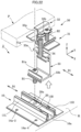
- FIG. 3 is an exploded perspective view of the trestle according to Embodiment 1;
- FIG. 4 is an (first) exploded cross-sectional view of the trestle according to Embodiment 1;
- FIG. 5 is a plan view of a base according to Embodiment 1;
- FIG. 6 is a cross-sectional view taken along line A-A of FIG. 4 ;
- FIG. 7 is an (second) exploded cross-sectional view of the trestle according to Embodiment 1;
- FIG. 8 is a (first) perspective view for explaining the effects of the trestle according to Embodiment 1;
- FIG. 9 A is a (second) perspective view for explaining the effects of the trestle according to Embodiment 1;
- FIG. 9 B is a (third) perspective view for explaining the effects of the trestle according to Embodiment 1;
- FIG. 10 A is a (first) cross-sectional view for explaining the effects of the trestle according to Embodiment 1;
- FIG. 10 B is a (second) cross-sectional view for explaining the effects of the trestle according to Embodiment 1;
- FIG. 11 is a (first) side view for explaining the effects of the trestle according to Embodiment 1;
- FIG. 12 is a (second) side view for explaining the effects of the trestle according to Embodiment 1;
- FIG. 13 is a (third) side view for explaining the effects of the trestle according to Embodiment 1;
- FIG. 14 is a (fourth) side view for explaining the effects of the trestle according to Embodiment 1;
- FIG. 15 A is a (third) cross-sectional view for explaining the effects of the trestle according to Embodiment 1, and is a drawing corresponding to a cross-section taken along line B-B of FIG. 4 ;
- FIG. 15 B is a (fourth) perspective view for explaining the effects of the trestle according to Embodiment 1;
- FIG. 16 is a perspective view of a trestle according to Embodiment 2.
- FIG. 17 is a side view of the trestle according to Embodiment 2.
- FIG. 18 is an exploded perspective view of the trestle according to Embodiment 2.
- FIG. 19 is a (first) perspective view for explaining the effects of the trestle according to Embodiment 2;
- FIG. 20 is a cross-sectional view for explaining the effects of the trestle according to Embodiment 2;
- FIG. 21 is a (second) perspective view for explaining the effects of the trestle according to Embodiment 2;
- FIG. 22 is a (third) perspective view for explaining the effects of the trestle according to Embodiment 2;
- FIG. 23 is a (fourth) perspective view for explaining the effects of the trestle according to Embodiment 2;
- FIG. 24 is a perspective view of a trestle according to Embodiment 3.
- FIG. 25 is a perspective view illustrating another use state of the trestle
- FIG. 26 is a perspective view of a trestle according to Embodiment 4.
- FIG. 27 is an exploded perspective view of the trestle according to Embodiment 4.
- FIG. 28 is a side view of the trestle according to Embodiment 4.
- FIG. 29 is a (first) side view for explaining the attaching of a cover to a fixing unit in the trestle according to Embodiment 4;
- FIG. 30 is a (second) side view for explaining the attaching of the cover to the fixing unit in the trestle according to Embodiment 4;
- FIG. 31 is a side view of a trestle according to Embodiment 5.
- FIG. 32 is an exploded side view of the trestle according to Embodiment 5;
- FIG. 33 is a (first) drawing of a spacer of the trestle according to Embodiment 5;
- FIG. 34 is a (second) drawing of the spacer of the trestle according to Embodiment 5;
- FIG. 35 is an (first) exploded perspective view of a trestle according to Embodiment 6;
- FIG. 36 is an (second) exploded perspective view of the trestle according to Embodiment 6;
- FIG. 37 is a perspective view of a trestle according to Embodiment 7.
- FIG. 38 is a plan view for explaining the effects of a base according to Embodiment 7.
- the trestle 1 is, for example, mounted on a roof surface R of a house and is used to support a solar panel P, as an installation object, installed on a surface of the roof surface R of the house.
- the house on which the trestle 1 is mounted is a structure that includes eaves, and ridges upward from the eaves.
- the trestle 1 according to Embodiment 1 includes a base 10 , a slide bracket 20 (slide member), and a fixing unit 30 .
- the trestle 1 includes a first fastener B 1 and a second fastener B 2 .
- the base 10 is a member that is mounted on the roof surface R of the house, and on which a first groove 10 a is formed.
- the base 10 is formed from a metal.
- the base 10 includes a groove forming portion 11 where the first groove 10 a is provided, and plate-like flange portions 14 R, 14 L formed projecting in the +Y direction and the ⁇ Y direction from the groove forming portion 11 .
- the first groove 10 a is formed along a first direction D 1 that is the same direction as an X-axis direction.
- This groove forming portion 11 includes a pair of side walls 11 R, 11 L, the first groove 10 a being formed on an inner side of the pair of side walls 11 R, 11 L.
- the second grooves 12 R, 12 L are formed so as to extend along the first direction (the X-axis direction), and a YZ cross-section thereof is formed in an L shape. As illustrated in FIG. 3 , slide restrictors 13 R, 13 L are formed in the second grooves 12 R, 12 L. Note that, in Embodiment 1, the slide restrictors 13 R, 13 L are respectively formed in the second grooves 12 R, 12 L and, thus, two are formed. However, the present disclosure is not limited thereto. The slide restrictors 13 R, 13 L may be formed in one of the second grooves 12 R, 12 L.
- the slide restrictors 13 R, 13 L are formed to restrict sliding, with respect to the base 10 , of the slide bracket 20 in the first direction.
- the slide restrictors 13 R, 13 L restrict sliding, with respect to the base 10 , of the slide bracket 20 in the +X direction.
- the slide restrictors 13 R, 13 L are configured as portions that are formed by a portion of the second grooves 12 R, 12 L being crushed due to the side walls 11 R, 11 L being pressed on by a tool or the like from the +Z side.
- the slide restrictors 13 R, 13 L may be formed by a method other than the method in which the side walls 11 R, 11 L are pressed on by a tool or the like from the +Z side.
- Fastener insertion holes 14 a - 1 to 14 a - 4 are formed, penetrating in a Z-axis direction, on the flange portions 14 R, 14 L.
- the fastener insertion holes 14 a - 1 to 14 a - 4 are round holes into which roof surface mounting fixtures 50 (see FIG. 2 ) are inserted.
- the fastener insertion holes 14 a - 3 and 14 a - 4 are provided more toward the eave side (downward, toward the +X side) in an eave-ridge direction than the fastener insertion holes 14 a - 1 and 14 a - 2 .
- the eave-ridge direction is a direction from the ridges toward the eaves of the house. Note that, in Embodiment 1, the eave-ridge direction is the same direction as the first direction D 1 .
- a spacing L 1 in a second direction D 2 orthogonal to the eave-ridge direction, between the fastener insertion holes 14 a - 1 and 14 a - 2 (first fastener insertion hole and second fastener insertion hole) is formed wider than a spacing L 2 between forming positions in the second direction of the fastener insertion holes 14 a - 3 and 14 a - 4 (third fastener insertion hole and fourth fastener insertion hole).
- the fastener insertion holes 14 a - 1 and 14 a - 2 are formed at positions at which the first groove 10 a is provided therebetween.
- the fastener insertion hole 14 a - 2 when viewed planarly, is formed at a position offset from a straight line L 3 that passes through the center of the fastener insertion hole 14 a - 1 and that is parallel to the Y-axis direction.
- the fastener insertion hole 14 a - 1 is formed at a position offset more in the eave-ridge direction (the X-axis direction) than the forming position of the fastener insertion hole 14 a - 2 .
- the fastener insertion hole 14 a - 2 is formed at a position more offset toward the +X side (downward) in the eave-ridge direction than the forming position of the fastener insertion hole 14 a - 1 .
- the fastener insertion holes 14 a - 3 , 14 a - 4 are formed at positions at which the first groove 10 a is provided therebetween. Moreover, when viewed planarly, the fastener insertion hole 14 a - 4 is formed at a position offset from a straight line L 4 that passes through the center of the fastener insertion hole 14 a - 3 and that is parallel to the Y-axis direction and to the straight line L 3 .
- the fastener insertion hole 14 a - 3 is formed at a position offset more in the eave-ridge direction (the X-axis direction) than the forming position of the fastener insertion hole 14 a - 4 .
- the fastener insertion hole 14 a - 4 is formed at a position more offset toward the +X side (downward) in the eave-ridge direction than the forming position of the fastener insertion hole 14 a - 3 .
- fastener insertion holes 14 a - 1 to 14 a - 4 are formed on the base 10 .
- the fastener insertion holes 14 a - 5 , 14 a - 6 are formed penetrating in the Z-axis direction, on a bottom surface of the first groove 10 a .
- the fastener insertion hole 14 a - 6 is provided more toward the eave side (downward, toward the +X side) in the eave-ridge direction than the fastener insertion hole 14 a - 5 .
- the fastener insertion hole 14 a - 5 is formed at a position offset more in the eave-ridge direction (the X-axis direction) than the forming positions of the fastener insertion holes 14 a - 1 , 14 a - 2 . More specifically, in Embodiment 1, the fastener insertion hole 14 a - 5 is formed at a position more offset toward the ⁇ X side (upward) in the eave-ridge direction than the forming positions of the fastener insertion holes 14 a - 1 , 14 a - 2 .
- the fastener insertion hole 14 a - 6 is formed at a position offset more in the eave-ridge direction (the X-axis direction) than the forming positions of the fastener insertion holes 14 a - 3 , 14 a - 4 . More specifically, in Embodiment 1, the fastener insertion hole 14 a - 6 is formed at a position more offset toward the +X side (downward) in the eave-ridge direction than the forming positions of the fastener insertion holes 14 a - 3 , 14 a - 4 .
- the slide bracket 20 (slide member) is fitted in the first groove 10 a of the base 10 so as to be slidable in the first direction D 1 .
- the slide bracket 20 is attached to the base 10 at a desired position in the first direction D 1 to perform positioning of the solar panel P in the first direction D 1 .
- the slide bracket 20 is formed from a metal and, specifically, is formed from a metal that is the same material as the base 10 .
- a screw hole 20 a is formed on the slide bracket 20 .
- the first fastener B 1 is screwed into the screw hole 20 a , and an inner circumferential surface of the screw hole 20 a is formed into a female screw surface.
- the screw hole 20 a is formed penetrating in the Z-axis direction.
- a pair of fitters 20 b is formed on the slide bracket 20 .
- the fitters 20 b are portions that fit in the second grooves 12 R, 12 L formed on the side walls 11 R, 11 L of the base 10 .
- the fitters 20 b are formed such that YZ cross-sections thereof are L-shaped.
- the fixing unit 30 fixes the solar panel P.
- the fixing unit 30 is installed on the slide bracket 20 by the first fastener B 1 .
- the fixing unit 30 is formed from a metal and, specifically, is formed from a metal that is the same material as the base 10 and the slide bracket 20 .
- the fixing unit 30 includes a receiving member 31 and a fixing unit main body 32 .
- the receiving member 31 is a fixture that receives the fixing unit main body 32 .
- a groove 31 a in which the fixing unit main body 32 is fitted is formed on the receiving member 31 along the Y-axis direction.
- a hole 31 e in which the first fastener B 1 is inserted and a screw hole 31 f in which the second fastener B 2 is inserted are formed penetrating in the Z-axis direction on a bottom surface of the groove 31 a.
- the hole 31 e is a hole having an inner circumferential surface that is not formed into a female screw surface.
- the screw hole 31 f is a hole having an inner circumferential surface that is formed into a female screw surface.
- a mounting surface 31 b (mount) and a pressure receiving surface 31 c are formed on the receiving member 31 .
- the mounting surface 31 b is provided on an upper surface (the +Z side surface) of an extension 31 - 3 (mount) extending from one side wall 31 - 1 of a pair of side walls 31 - 1 , 31 - 2 , the groove 31 a being formed on the inner side of the side walls 31 - 1 , 31 - 2 .
- the solar panel P which is the installation object of the trestle 1 , is mounted on the mounting surface 31 b .
- the mounting surface 31 b is configured from a surface roughly parallel to the XY plane, and a portion of the mounting surface 31 b is formed recessed. The portion of the mounting surface 31 b that is formed recessed is formed as a depression 31 d.
- the pressure receiving surface 31 c is a surface that receives the weight of the solar panel P that is fixed by the fixing unit 30 .
- the pressure receiving surface 31 c is formed on the ⁇ X side surface of the side wall 31 - 1 , and is formed on a surface parallel to the YZ plane.
- the fixing unit main body 32 is a fixture that is fixed to the receiving member 31 by the second fastener B 2 .
- the fixing unit main body 32 includes side walls 32 - 1 , 32 - 2 , coupling plates 32 - 3 , 32 - 4 , and extensions 32 - 5 , 32 - 6 .
- the side walls 32 - 1 , 32 - 2 are formed in a plate shape parallel to the YZ plane.
- the side wall 32 - 1 is provided overlapping the side wall 31 - 1 of the receiving member 31 , with a gap between the side wall 32 - 1 and the side wall 31 - 1 .
- the side wall 32 - 2 is provided overlapping the side wall 31 - 2 of the receiving member 31 , with a gap between the side wall 32 - 2 and the side wall 31 - 2 .
- the coupling plates 32 - 3 , 32 - 4 are formed in a plate shape parallel to the XY plane. These coupling plates 32 - 3 , 32 - 4 couple the side walls 32 - 1 , 32 - 2 . Due to the side walls 32 - 1 , 32 - 2 being coupled by the two coupling plates 32 - 3 , 32 - 4 , the strength of the fixing unit main body 32 is enhanced.
- a groove extending the Y-axis direction is formed on the inner side of the coupling plate 32 - 3 , disposed upward (on the +Z side) from the coupling plate 32 - 4 , and the side walls 32 - 1 , 32 - 2 . As illustrated in FIG. 7 , a hole in which the second fastener B 2 is inserted is formed on the coupling plate 32 - 3 . Likewise, a hole in which the second fastener B 2 is inserted is also formed on the coupling plate 32 - 4 .
- the extension 32 - 5 extends from an upper end (+Z side end) of the side wall 32 - 1 .
- a lower surface of the extension 32 - 5 ( ⁇ Z side surface) functions as a surface that holds down and fixes the solar panel P to the mounting surface 31 b .
- the extension 32 - 5 is formed such that a length in the extending direction (length in the X-axis direction) thereof is shorter than a length in the extending direction (length in the X-axis direction) of the extension 31 - 3 of the receiving member 31 .
- the extension 32 - 6 extends from an upper end (+Z side end) of the side wall 32 - 2 in a direction opposite the extending direction of the extension 32 - 5 .
- a lower surface of the extension 32 - 6 ( ⁇ Z side surface) functions as a surface that holds down and fixes the solar panel P.
- holes 32 a , 32 b penetrating in the Z-axis direction are respectively formed on the coupling plates 32 - 3 , 32 - 4 .
- a portion of a +Z side head of the first fastener B 1 is exposed to the outside through these holes 32 a , 32 b .
- the holes 32 a , 32 b are formed having a size such that the head of the first fastener B 1 does not pass through in the Z-axis direction.
- the first fastener B 1 is constituted from a bolt or a screw, for example.
- the first fastener B 1 is attached to the slide bracket 20 and the fixing unit 30 by being rotated around an axis.
- the first fastener B 1 is attached to the slide bracket 20 and the fixing unit 30 such that the fixing between the slide bracket 20 and the fixing unit 30 can be released while maintaining the fixing between the receiving member 31 and the fixing unit main body 32 by the second fastener B 2 .
- the first fastener B 1 is attached to the slide bracket 20 and the fixing unit 30 such that a lower end of the first fastener B 1 protrudes into the first groove 10 a of the base 10 .
- a fitted hole B 1 a (first fitted member), in which a tool for releasing the fixing of the slide bracket 20 and the fixing unit 30 fits, is formed on the first fastener B 1 .
- the fitted hole B 1 a of the first fastener B 1 is exposed to the outside in the Z-axis direction (axial direction of the first fastener B 1 ) through the holes 32 a , 32 b formed on the fixing unit main body 32 .
- the second fastener B 2 is constituted from a bolt or a screw, for example.
- the second fastener B 2 is attached to the fixing unit 30 by being rotated around an axis.
- the second fastener B 2 is provided such that an axis thereof is parallel to the axis of the first fastener B 1 .
- the second fastener B 2 is attached to fixing unit 30 such that a lower end of the second fastener B 2 protrudes out from the groove forming portion 11 of the base 10 .
- the fitted hole B 1 a of the first fastener B 1 is exposed to the outside in the Z-axis direction through the holes 32 a , 32 b .
- the first fastener B 1 is attached such that the fixing between the slide bracket 20 and the fixing unit 30 can be released while maintaining the fixing between the receiving member 31 and the fixing unit main body 32 by the second fastener B 2 .
- the trestle 1 it is possible to remove the fixing unit 30 from the slide bracket 20 while the solar panel P is fixed by the fixing unit 30 .
- the trestle 1 according to Embodiment 1 can enhance the work efficiency when carrying out installation/removal work on the roof surface R of the house.
- the holes 32 a , 32 b that expose the fitted hole B 1 a of the first fastener B 1 to the outside are formed on the fixing unit main body 32 .
- the holes 32 a , 32 b are formed penetrating in the Z-axis direction. As such, it is easier for a user to fit the tool in the fitted hole B 1 a of the first fastener B 1 by inserting the tool in the holes 32 a , 32 b .
- the trestle 1 according to Embodiment 1 can enhance the work efficiency when carrying out installation/removal work on the roof surface R of the house.
- the user can perform positioning of the solar panel P in the first direction D 1 by attaching the slide bracket 20 to the base 10 at a desired position in the first direction D 1 .
- the trestle 1 according to Embodiment 1 can enhance the work efficiency when carrying out installation/removal work on the roof surface R of the house.
- the first fastener B 1 is screwed into the screw hole 20 a .
- the fixing unit 30 can be fixed to the base 10 by rotating the first fastener B 1 in the screw hole 20 a .
- the first fastener B 1 is loosened, a fitting 60 formed in a U-shape, for example, is inserted as a spacer in the gap between the base 10 and the fixing unit 30 , and the fixing unit 30 is fixed again using the first fastener B 1 .
- the trestle 1 according to Embodiment 1 can enhance the work efficiency when carrying out installation/removal work on the roof surface R of the house.
- the shape of the fitting 60 is not limited to a U-shape.
- the fitting 60 may have a shape other than a U-shape, provided that the fitting 60 functions as a spacer to be inserted in the gap between the base 10 and the fixing unit 30 .
- the second fastener B 2 is attached to the fixing unit 30 such that the lower end of the second fastener B 2 protrudes out from the groove forming portion 11 of the base 10 .
- the fixing unit 30 when the fixing unit 30 is rotated around the axis of the first fastener B 1 with respect to the base 10 , the lower end of the second fastener B 2 interferes with the groove forming portion 11 of the base 10 . Due to this, the fixing unit 30 does not rotate more than a predetermined amount with respect to the base 10 .
- the trestle 1 according to Embodiment 1 can enhance the work efficiency when carrying out installation/removal work on the roof surface R of the house.
- the pressure receiving surface 31 c that receives the weight of the solar panel P fixed by the fixing unit 30 is formed on the receiving member 31 .
- the fixing unit main body 32 is fitted into the groove 31 a formed in the receiving member 31 and, as such, is formed so as not to receive the weight of the solar panel P.
- the user can remove the receiving member 31 from the fixing unit main body 32 while the fixing unit main body 32 is attached to the base 10 .
- the user can easily carry out installation and removal of the solar panel P when performing maintenance.
- the fixing unit main body 32 is formed so as not to receive the weight of the solar panel P and, as such, adjustment of the height of the fixing unit main body 32 with respect to the receiving member 31 is facilitated.
- the trestle 1 according to Embodiment 1 can enhance the work efficiency when carrying out installation/removal work on the roof surface R of the house.
- the mounting surface 31 b of the receiving member 31 includes the depression 31 d that is formed by recessing a portion of the mounting surface 31 b .
- the user when attaching the solar panel P to the fixing unit 30 , as illustrated in FIGS. 13 and 14 , the user inserts the solar panel P toward the depression 31 d from a third direction D 3 inclined with respect to the mounting surface 31 b and, then, rotates the solar panel P in a rotation direction D 4 having an edge E on the insertion direction leading end side of the solar panel P as a base point to mount the solar panel P on the mounting surface 31 b .
- the user rotates the second fastener B 2 and, as a result, the extension 32 - 5 holds down and tightens the solar panel P to the mounting surface 31 b .
- the solar panel P is fixed by the fixing unit 30 .
- the user can carry out installation of the solar panel P and the trestle 1 without getting on the solar panel P from the ridge side (the ⁇ X side).
- the trestle 1 according to Embodiment 1 can enhance the work efficiency when carrying out installation/removal work on the roof surface R of the house.
- the slide restrictors 13 R, 13 L are formed on the second grooves 12 R, 12 L formed on the respective opposing surfaces of the pair of side walls 11 R, 11 L.
- the slide restrictors 13 R, 13 L restrict sliding in the +X direction of the slide bracket 20 and the fixing unit 30 with respect to the base 10 , as illustrated in FIG. 3 .
- the trestle 1 according to Embodiment 1 can enhance the work efficiency when carrying out installation/removal work on the roof surface R of the house.
- the slide restrictors 13 R, 13 L are portions that are formed by the second grooves 12 R, 12 L being crushed due to the side walls 11 R, 11 L being pressed on. As such, the slide restrictors 13 R, 13 L can be easily formed.
- the spacing L 1 between the fastener insertion holes 14 a - 1 , 14 a - 2 is formed wider than the spacing L 2 between the fastener insertion holes 14 a - 3 , 14 a - 4 .
- the base 10 can be formed such that the mounting strength to the roof surface of the fastener insertion holes 14 a - 1 , 14 a - 2 is greater than the mounting strength to the roof surface of the fastener insertion holes 14 a - 3 , 14 a - 4 . Due to this, the mounting strength of the base 10 with respect to the roof surface can be enhanced. As a result, the trestle 1 according to Embodiment 1 can enhance the work efficiency when carrying out installation/removal work on the roof surface of the house.
- the side wall 32 - 1 of the fixing unit main body 32 is provided overlapping the side wall 31 - 1 of the receiving member 31 , with a gap between the side wall 32 - 1 and the side wall 31 - 1 .
- the trestle 1 can use the side wall 31 - 1 and the side wall 32 - 1 to replace the solar panel P with a solar panel P- 2 of a different thickness, and fix the solar panel P- 2 using the fixing unit 30 .
- the trestle 1 can fix the solar panel P, P- 2 regardless of the thickness of the solar panel P, P- 2 .
- the trestle 1 according to Embodiment 1 can enhance the work efficiency when carrying out installation/removal work on the roof surface R of the house.
- the fastener insertion holes 14 a - 1 to 14 a - 6 are formed at positions offset in the eave-ridge direction. As such, as illustrated in FIGS. 6 and 15 B , it is possible to prevent all roof surface mounting fixtures that are inserted into the fastener insertion holes 14 a - 1 to 14 a - 6 from being stuck into the gaps between roofing boards R 1 of the roof surface R. Thus, the mounting strength of the base 10 with respect to the roof surface R can be enhanced. As a result, the trestle 1 according to Embodiment 1 can enhance the work efficiency when carrying out installation/removal work on the roof surface R of the house.
- the fixing unit 30 includes the receiving member 31 and the fixing unit main body 32 as illustrated in FIG. 2 .
- the present disclosure is not limited thereto.
- a configuration is possible in which, in addition to the receiving member 31 and the fixing unit main body 32 , the fixing unit 30 includes a member for adjusting the height of the solar panel P.
- a trestle 2 according to Embodiment 2 of the present disclosure is described using the drawings. The following description focuses on the differences with Embodiment 1. With the exception of these differences, the trestle 2 according to Embodiment 2 is the same as or equivalent to the trestle 1 of Embodiment 1. Note that, to facilitate comprehension, XYZ coordinates are set and appropriately referenced.
- the trestle 2 includes a base 10 , a slide bracket 20 (slide member), and a fixing unit 30 . Additionally, the trestle 2 includes a first fastener B 1 and a second fastener B 2 .
- the base 10 , the slide bracket 20 , the first fastener B 1 , and the second fastener B 2 are the same as in Embodiment 1.
- the fixing unit 30 includes a receiving member 31 , a fixing unit main body 32 and, additionally, a relay member 33 and a third fastener 34 .
- the hole 31 e has an inner circumferential surface that is formed into a female screw surface.
- the third fastener 34 is screwed into the hole 31 e.
- a hole 31 g is provided on an extension 31 - 3 .
- the hole 31 g is formed such that a cross-section thereof is substantially oval. Additionally, the hole 31 g is formed penetrating in the Z-axis direction.
- the fixing unit main body 32 is the same as in Embodiment 1.
- a rotation restrictor 33 b is formed on the relay member 33 .
- the rotation restrictor 33 b restricts the rotation, around the axis of the third fastener 34 , of the relay member 33 with respect to the base 10 .
- two rotation restrictors 33 b are formed on the relay member 33 .
- One rotation restrictor 33 b may be formed on the relay member 33 .
- the third fastener 34 is constituted from a bolt or a screw, for example.
- the third fastener 34 is attached to the relay member 33 and the receiving member 31 by being rotated around the axis.
- the receiving member 31 is provided so as to be liftable/lowerable with respect to the relay member 33 by the third fastener 34 being rotated around the axis.
- a fitted hole 34 a (second fitted member), in which a tool for releasing the fixing of the receiving member 31 and relay member 33 fits, is formed on the third fastener 34 .
- the fitted hole 34 a of the third fastener 34 is exposed to the outside in the Z-axis direction (axial direction of the third fastener 34 ) through the holes 32 a , 32 b formed in the fixing unit main body 32 .
- a fitted hole B 1 a (first fitted member) of the first fastener B 1 is exposed to the outside in the Z-axis direction (axial direction of the first fastener B 1 ) through the hole 31 g formed on the receiving member 31 and the notch 33 a formed in the relay member 33 .
- the fitted hole B 1 a of the first fastener B 1 is exposed to the outside in the Z-axis direction through the hole 31 g and the notch 33 a .
- the first fastener B 1 is attached such that the fixing between the slide bracket 20 and the fixing unit 30 can be released while maintaining the fixing between the receiving member 31 , the fixing unit main body 32 , and the relay member 33 by the second fastener B 2 .
- the trestle 2 it is possible to remove the fixing unit 30 from the slide bracket 20 while the solar panel P is fixed by the fixing unit 30 .
- the trestle 2 according to Embodiment 2 can enhance the work efficiency when carrying out installation/removal work on the roof surface R of the house.
- the fitted hole 34 a of the third fastener 34 is exposed to the outside in the Z-axis direction through the holes 32 a , 32 b .
- the third fastener 34 is attached such that the receiving member 31 and the fixing unit main body 32 can be removed from the relay member 33 while maintaining the fixing between the receiving member 31 and the fixing unit main body 32 by the second fastener B 2 .
- the trestle 2 it is possible to remove the receiving member 31 and the fixing unit main body 32 from the base 10 or the relay member 33 while the solar panel P is fixed to the receiving member 31 and the fixing unit main body 32 .
- the trestle 2 according to Embodiment 2 can enhance the work efficiency when carrying out installation/removal work on the roof surface R of the house.
- the fixing unit 30 includes the relay member 33 .
- the trestle 2 can change the installation position in the height direction of the solar panel P.
- the third fastener 34 is screwed into the screw hole of the receiving member 31 .
- the receiving member 31 and the fixing unit main body 32 are provided so as to be capable of lifting/lowering with respect to the relay member 33 by the third fastener 34 being rotated with respect to the screw hole of the receiving member 31 .
- the trestle 2 it is possible to lift/lower the receiving member 31 and the fixing unit main body 32 with respect to the relay member 33 while the solar panel P is fixed to the receiving member 31 and the fixing unit main body 32 .
- the trestle 2 according to Embodiment 2 can enhance the work efficiency when carrying out installation/removal work on the roof surface R of the house.
- the second fastener B 2 is attached to the fixing unit 30 such that the lower end of the second fastener B 2 protrudes out from the relay member 33 .
- the lower end of the second fastener B 2 interferes with the relay member 33 .
- the receiving member 31 and the fixing unit main body 32 do not rotate more than a predetermined amount with respect to the relay member 33 and the base 10 .
- the trestle 2 according to Embodiment 2 can enhance the work efficiency when carrying out installation/removal work on the roof surface R of the house.
- the rotation restrictor 33 b is formed on the relay member 33 .
- the rotation restrictor 33 b restricts the relay member 33 from rotating around the axis of the third fastener 34 with respect to the base 10 .
- the trestle 2 according to Embodiment 2 can enhance the work efficiency when carrying out installation/removal work on the roof surface R of the house.
- a pressure receiving surface 31 c that receives the weight of the solar panel P fixed by the fixing unit 30 is formed on the receiving member 31 .
- the fixing unit main body 32 is fitted into the groove 31 a formed in the receiving member 31 and, as such, is formed so as not to receive the weight of the solar panel P.
- the trestle 2 according to Embodiment 2 can enhance the work efficiency when carrying out installation/removal work on the roof surface R of the house.
- a mounting surface 31 b of the receiving member 31 includes a depression 31 d that is formed by recessing a portion of the mounting surface 31 b .
- the base 10 according to Embodiment 2 has a structure equivalent to that of Embodiment 1 and, as such, can demonstrate effects equivalent to those of Embodiment 1.
- one second fastener B 2 of the trestle 1 , 2 is provided.
- the present disclosure is not limited thereto.
- a configuration is possible in which a trestle 3 includes two second fasteners B 2 .
- the trestle 3 can fix two solar panels P arranged from the eave side.
- the first fastener B 1 is constituted from a bolt or a screw that is attached to the slide bracket 20 and the fixing unit 30 by being rotated around the axis.
- the first fastener B 1 may be a member other than a bolt or a screw.
- the second fastener B 2 is constituted from a bolt or a screw that is attached to the fixing unit 30 by being rotated around the axis.
- the second fastener B 2 may be a member other than a bolt or a screw.
- the third fastener 34 is constituted from a bolt or a screw that is attached to the relay member 33 and the receiving member 31 by being rotated around the axis.
- the third fastener 34 may be a member other than a bolt or a screw.
- the holes 32 a , 32 b that expose the fitted hole B 1 a to the outside are formed on the fixing unit 30 .
- the present disclosure is not limited thereto.
- a shape other than a hole may be used.
- a notch that exposes the fitted hole B 1 to the outside may be formed on the fixing unit 30 .
- the fitted hole B 1 a is formed on the first fastener B 1 as a portion in which a tool is fitted.
- the present disclosure is not limited thereto. Provided that a portion is provided in which a tool is fitted, a shape other than a hole may be used.
- the fitted hole is formed on the second fastener B 2 as a portion in which a tool is fitted.
- the present disclosure is not limited thereto. Provided that a portion is provided in which a tool is fitted, a shape other than a hole may be used.
- the hole 31 g and the notch 33 a that expose the fitted hole 34 a to the outside are formed on the fixing unit 30 .
- the present disclosure is not limited thereto.
- a shape other than a hole or a notch may be used.
- the fitted hole 34 a is formed on the third fastener 34 as a portion in which a tool is fitted.
- the present disclosure is not limited thereto. Provided that a portion is provided in which a tool is fitted, a shape other than a hole may be used.
- the holes 32 a , 32 b that expose the fitted hole B 1 a to the outside are formed on the fixing unit 30 .
- the present disclosure is not limited thereto.
- a shape other than a hole may be used.
- a notch that exposes the fitted hole B 1 a to the outside may be formed on the fixing unit 30 .
- the six fastener insertion holes 14 a - 1 to 14 a - 6 are formed on the base 10 .
- the forming positions of the base 10 and the number of fastener insertion holes that are formed can be appropriately changed.
- the trestle 1 is mounted on the roof surface R such that the first direction D 1 , which is the forming direction of the first groove 10 a of the base 10 , matches the eave-ridge direction of the house.
- the present disclosure is not limited thereto.
- the trestle 1 may by mounted on the roof surface R such that the first direction D 1 , which is the forming direction of the first groove 10 a of the base 10 , does not match a direction D 5 , which is the eave-ridge direction of the house. Any direction can be used for the mounting direction of the trestle 1 , and the mounting direction can be appropriately changed.
- the trestles 1 to 3 are mounted on the roof of the house and fix the solar panel P.
- the trestles 1 to 3 may be mounted on a surface other than the roof of the house and support the solar panel P.
- the trestles 1 to 3 may support the solar panel P on the ground.
- the trestles 1 to 3 are for fixing a solar panel.
- the trestles 1 to 3 may support an object to be installed on the roof of the house other than a solar panel.
- the trestles 1 to 3 may support a water heater panel.
- the trestles 1 to 3 can support any object that is a framed panel.
- the trestles 1 to 3 may support objects other than framed panels.
- the fixing unit 30 is exposed to the eave side (the +X side) as illustrated in FIG. 17 .
- the present disclosure is not limited thereto.
- FIGS. 26 and 27 a configuration is possible in which a trestle 4 includes a cover 70 .
- a trestle 4 according to Embodiment 4 of the present disclosure is described using the drawings. The following description focuses on the differences with Embodiment 2. With the exception of these differences, the trestle 4 according to Embodiment 4 is the same as or equivalent to the trestle 2 of Embodiment 2. Note that, to facilitate comprehension, XYZ coordinates are set and appropriately referenced.
- the trestle 4 according to Embodiment 4 includes a cover 70 in addition to a fixing unit 30 and the like.
- a base 10 , a slide bracket 20 , a fixing unit 30 , a first fastener B 1 , and a second fastener B 2 of the trestle 4 are the same as in Embodiment 2.
- an eave-side mounting surface 31 b - 2 is formed on a receiving member 31 of the fixing unit 30 .
- the mounting surface 31 b - 2 is provided on an upper surface (+Z side surface) of an extension 31 - 4 extending in a direction (the +X direction) opposite an extension 31 - 3 on which the mounting surface 31 b is formed.
- a portion of the cover 70 is mounted on the mounting surface 31 b - 2 .
- an engaged portion 31 h is formed on the mounting surface 31 b - 2 .
- an extension 32 - 6 of a fixing unit main body 32 is formed facing the mounting surface 31 b - 2 so as to sandwich the portion of the cover 70 mounted on the mounting surface 31 b - 2 .
- the cover 70 is a member that covers a portion of the fixing unit 30 from the outside. Specifically, the cover 70 is formed so as to cover the eave-side (the +X side), in the eave-ridge direction (the X-axis direction) of the house, of the fixing unit 30 .
- the cover 70 is constituted from an electrically conductive material.
- the cover 70 is formed by extruding a metal. Specifically, in one example, the cover 70 is formed by extruding aluminum and, then, subjecting the surface thereof to black color alumite treatment. As a result, the silver color, which is the color of the aluminum itself, is covered.
- the cover 70 covers a portion of the fixing unit 30 , but the present disclosure is not limited thereto, and the cover 70 may cover an entirety of the fixing unit 30 .
- the cover 70 according to Embodiment 4 includes a cover main body 71 , and a tubular portion 72 for assembling the cover main body 71 on the fixing unit 30 .
- the tubular portion 72 is formed in a rectangular tube shape that extends in the Y-axis direction.
- the tubular portion 72 is a portion that is disposed between the mounting surface 31 b - 2 of the receiving member 31 and the extension 32 - 6 of the fixing unit main body 32 .
- An engager 73 is formed on a lower surface (surface toward the ⁇ Z side) of the tubular portion 72 .
- the engager 73 engages the engaged portion 31 h formed on the mounting surface 31 b - 2 of the receiving member 31 .
- the cover 70 is fixed to the fixing unit 30 due to the engager 73 engaging the engaged portion 31 h.
- bends 74 , 75 are formed on the cover main body 71 in the proximity of an upper end (end toward the +Z side) and a lower end (end toward the ⁇ Z side) of the cover main body 71 .
- the bend 74 is formed by bending a portion of the upper end of the cover main body 71 inward so as to catch on a base end portion 32 - 6 a of the extension 32 - 6 of the fixing unit main body 32 .
- the bend 74 is used together with the engager 73 to fix the cover 70 to the fixing unit 30 .
- the bend 75 is shaped such that a portion of the lower end of the cover main body 71 bends inward.
- the bend 75 is formed to enhance the strength of the lower end of the cover 70 .
- the bend 75 is not formed on the cover main body 71 of the cover 70
- the lower end of the cover 70 is formed in a simple thin plate form and, consequently, is more likely to deform due to the application of an external force.
- Embodiment 4 can prevent the lower end of the cover 70 from being more likely to deform due to the application of an external force.
- the flow of aluminum, which is the material of the cover 70 can be enhanced when forming the cover 70 by extruding.
- the flow of the aluminum, which is the material of the cover 70 worsens when forming the cover 70 by extruding. Due to this, the aluminum may not flow uniformly to the lower end, and forming the lower end of the cover 70 into the desired shape may not be possible.
- the bend 75 is formed on the cover 70 and, as such, an effect of distributing the aluminum, which is the material of the cover 70 , up to the bend 75 , which is the lower end of the cover 70 , can be obtained. As a result, the Embodiment 4 can enhance the manufacturing efficiency of the cover 70 .
- the user When attaching the cover 70 configured as described above to the fixing unit 30 , the user firstly hooks the bend 74 of the cover 70 on the base end portion 32 - 6 a of the extension 32 - 6 of the fixing unit main body 32 . Then, as illustrated in FIG. 30 , the user rotates the cover 70 around the portion on which the bend 74 is hooked. As a result, the tubular portion 72 of the cover 70 is fitted between the extension 32 - 6 of the fixing unit main body 32 and the extension 31 - 4 of the receiving member 31 .
- the engager 73 of the cover 70 engages the engaged portion 31 h formed on the extension 31 - 4 of the receiving member 31 .
- the cover 70 is fixed to the fixing unit main body 32 so as not to detach from the fixing unit main body 32 .
- the trestle 4 includes the cover 70 that covers a portion of the fixing unit 30 .
- the cover 70 covers the eave side (the +X side) of the house of the fixing unit 30 .
- the fixing unit 30 supporting the solar panel P is not exposed to the eave side (the +X side) and the aesthetic of the house on which the trestle 4 is mounted is not compromised.
- the trestle 4 can enhance the aesthetic.
- the bend 74 that hooks on the fixing unit main body 32 is formed on the upper end of the cover main body 71 .
- the bend 74 that hooks on the fixing unit main body 32 is formed on the upper end of the cover main body 71 .
- the trestle 4 according to Embodiment 4 can demonstrate the same effects as in Embodiments 1 to 3. As such, the trestle 4 also can enhance the work efficiency when carrying out installation/removal work on the roof surface R of the house.
- the fixing unit 30 includes a relay member 33 and, as such, the height (length in the Z-axis direction) of the fixing unit 30 is great, and the fixing unit 30 is more likely to be exposed to the eave side. Therefore, the aesthetic attributable to the covering by the cover 70 can be further enhanced.
- the present disclosure is not limited thereto. A configuration is possible in which the fixing unit 30 (see FIGS. 1 and 2 ) described in Embodiment 1, which does not include the relay member 33 , is covered by the cover 70 .
- Embodiment 4 as illustrated in FIG. 29 , the tubular portion 72 of the cover 70 is disposed so as to be sandwiched between the mounting surface 31 b - 2 of the receiving member 31 and the extension 32 - 6 of the fixing unit main body 32 .
- the present disclosure is not limited thereto.
- a trestle 5 includes a spacer 80 that is fitted together with the tubular portion 72 of the cover 70 between the mounting surface 31 b - 2 and the extension 32 - 6 .
- the spacer 80 is formed by extruding a metal.
- a protrusion 81 and an engaged portion 82 are formed on the spacer 80 .
- the protrusion 81 is a rod-like part that protrudes in the +Y direction.
- the protrusion 81 is inserted into the groove 31 a of the receiving member 31 of the fixing unit 30 . Due to this, the spacer 80 hooks on the fixing unit 30 , and the work efficiency when attaching the cover 70 to the fixing unit 30 can be enhanced.
- the engaged portion 82 is a portion that the engager 73 of the cover 70 engages with instead of the engaged portion 31 h formed on the receiving member 31 .
- the spacer 80 is formed such that a thickness t 1 (length in the Z-axis direction) thereof is substantially equal to a height obtained by subtracting a height H 2 (length in the Z-axis direction) of the tubular portion 72 of the cover 70 from a height H 1 between the mounting surface 31 b - 2 and the extension 32 - 6 (t 1 ⁇ H 1 ⁇ H 2 ).
- the height H 1 in the Z-axis direction between the mounting surface 31 b - 2 and the extension 32 - 6 changes depending on the thickness of the solar panel P and, as such, the user can, in accordance with the thickness of the solar panel P, replace the spacer 80 with a spacer 80 - 2 (spacer having a thickness t 2 thinner than the thickness t 1 ) illustrated in FIG. 33 , or a spacer 80 - 3 (spacer having a thickness t 3 thinner than the thicknesses t 1 and t 2 ) illustrated in FIG. 34 that have different thicknesses.
- the trestle 5 includes the spacer 80 that can be fitted together with the tubular portion 72 of the cover 70 between the mounting surface 31 b - 2 and the extension 32 - 6 .
- the spacer 80 can be fitted together with the tubular portion 72 of the cover 70 between the mounting surface 31 b - 2 and the extension 32 - 6 .
- the trestle 5 can enhance the work efficiency when carrying out installation/removal work on the roof surface of the house, regardless of the thickness of the solar panel P as the installation object.
- the trestles 4 , 5 include one cover 70 .
- the present disclosure is not limited thereto.
- a configuration is possible in which a trestle 6 includes a plurality of covers 70 .
- a trestle 6 according to Embodiment 6 that includes two covers 70 is described. The description focuses on the differences with Embodiments 4 and 5. With the exception of these differences, the trestle 6 according to Embodiment 6 is the same as or equivalent to the trestles 4 and 5 of Embodiments 4 and 5.
- the trestle 6 includes two covers 70 , and a joint 90 .
- the joint 90 is constituted from an electrically conductive material.
- the joint 90 is formed by extruding an electrically conductive metal material.
- the joint 90 is formed in a shape capable of fitting in tube holes of the tubular portions 72 of the covers 70 .
- the joint 90 is inserted into the tube holes of the tubular portions 72 to connect the two covers 70 .
- the two covers 70 are electrically connected due to the joint 90 connecting the two covers 70 .
- the need for a ground line between the solar panel P to be fixed by the fixing unit 30 and a separate solar panel P can be eliminated.
- the base main body 15 that includes the groove forming portion 11 and the flange portions 14 R, 14 L is formed in a rectangular shape in which all four corners 16 are formed at right angles.
- the present disclosure is not limited thereto.
- a trestle 7 according to Embodiment 7, in which the shape of the base main body 15 is different, is described using FIGS. 37 and 38 .
- the description focuses on the differences with Embodiment 1. With the exception of these differences, the trestle 7 according to Embodiment 7 is the same as or equivalent to the trestle 1 of Embodiment 1.
- the base main body 15 is formed in a rectangular plate shape in which the two ridge-side corners are machined. Specifically, in this base main body 15 , inclined surfaces 17 R, 17 L inclined with respect to the first direction D 1 are formed on the corners on the ridge-side of the rectangular plate shape. In one example, the inclined surfaces 17 R, 17 L are formed into flat surfaces inclined with respect to the first direction D 1 . Due to these inclined surfaces 17 R, 17 L being formed, as illustrated by arrow A 3 of FIG.
- the trestle 7 can direct rainwater, flowing from the ridge side, in the eave direction (the +X direction), while dividing the rainwater to the left and right, namely, to the ⁇ Y side and the +Y side.
- the inclined surfaces 17 R, 17 L are flat surfaces.
- the present disclosure is not limited thereto.
- the shape is capable of directing rainwater, flowing from the ridge side, in the eave direction (the +X direction) while dividing the rainwater to the left and right
- the inclined surfaces 17 R, 17 L may be provided with a shape other than a flat surface.
- the inclined surfaces 17 R, 17 L may be formed into rounded surfaces.
- the present disclosure is suitable for use as a trestle that is mounted on a roof surface of a house, and that supports a solar panel installed on a surface of the roof surface.
Landscapes
- Engineering & Computer Science (AREA)
- Architecture (AREA)
- Civil Engineering (AREA)
- Structural Engineering (AREA)
- Physics & Mathematics (AREA)
- Life Sciences & Earth Sciences (AREA)
- Sustainable Development (AREA)
- Sustainable Energy (AREA)
- Thermal Sciences (AREA)
- Chemical & Material Sciences (AREA)
- Combustion & Propulsion (AREA)
- Mechanical Engineering (AREA)
- General Engineering & Computer Science (AREA)
- Roof Covering Using Slabs Or Stiff Sheets (AREA)
Abstract
Description
-
- a base that is mounted on a roof surface of a house and on which a first groove is formed along a first direction;
- a slide member fitted in the first groove so as to be slidable in the first direction;
- a fixing unit installed on the slide member and for fixing an installation object to be installed on a surface of the roof surface;
- a first fastener for fixing the fixing unit to the slide member; and
- a second fastener attached to the fixing unit, wherein
- the fixing unit includes
- a receiving member on which a mount, on which the installation object is mounted, is formed, and
- a fixing unit main body that is formed capable of holding down and fixing the installation object to the mount by the second fastener, and that is fixed to the receiving member, and
- the first fastener is attached such that fixing between the slide member and the fixing unit can be released while maintaining the fixing between the receiving member and the fixing unit main body by the second fastener.
-
- the first fitted member may be exposed to an outside in at least an axial direction of the first fitted member.
-
- the second fastener may be provided such that the axis of the second fastener is parallel to the axis of the first fastener.
-
- a relay member that is fixed to the slide member and that is for increasing a height of the installation object with respect to the base by supporting the receiving member.
-
- a third fastener that supports the receiving member on the relay member and is configured from a member that attaches to the relay member and the receiving member by being rotated around an axis, and
- the receiving member may be provided liftable with respect to the relay member by the third fastener being rotated around the axis.
-
- the second fitted member may be exposed to an outside in at least an axial direction of the third fitted member.
-
- a pair of second grooves, in which a portion of the slide member is fit and that is formed along the first direction, may be formed on respective opposing surfaces of the pair of side walls.
-
- the base may include:
- a first fastener insertion hole and a second fastener insertion hole into which a roof surface mounting fixture for mounting on the roof surface is inserted, and
- a third fastener insertion hole and a fourth fastener insertion hole into which the roof surface mounting fixture is inserted and that are provided more toward the eave in an eave-ridge direction, that is a direction from the ridge toward the eave of the house, than the first fastener insertion hole and the second fastener insertion hole, and
- a spacing, in a second direction orthogonal to the eave-ridge direction, between the first fastener insertion hole and the second fastener insertion hole may be formed wider than a spacing between forming positions in the second direction of the third fastener insertion hole and the fourth fastener insertion hole.
- the base may include:
-
- the first fastener insertion hole may be formed at a position more offset in the eave-ridge direction than a forming position of the second fastener insertion hole.
-
- the third fastener insertion hole may be formed at a position more offset in the eave-ridge direction than the forming position of the fourth fastener insertion hole.
-
- the house may be a structure including an eave, and a ridge disposed upward from the eave, and
- in the fixing unit, the cover covers an eave side in an eave-ridge direction that is a direction from the ridge to the eave of the house.
-
- the house may be a structure including an eave, and a ridge disposed upward from the eave, and
- in the base main body, an inclined surface inclined with respect to the first direction may be formed at corners on the ridge side of the rectangular plate shape.
-
- 1, 2, 3, 4, 5, 6, 7 Trestle
- 10 Base
- 10 a First groove
- 11 Groove forming portion
- 11R, 11L Side wall
- 12R, 12L Second groove
- 13R, 13L Slide restrictor
- 14R, 14L Flange portion
- 14 a-1 Fastener insertion hole (first fastener insertion hole)
- 14 a-2 Fastener insertion hole (second fastener insertion hole)
- 14 a-3 Fastener insertion hole (third fastener insertion hole)
- 14 a-4 Fastener insertion hole (fourth fastener insertion hole)
- 14 a-5, 14 a-6 Fastener insertion hole
- 15 Base main body
- 16 Corner
- 17R, 17L Inclined surface
- 20 Slide bracket (slide member)
- 20 a Screw hole
- 20 b Fitter
- 30 Fixing unit
- 31 Receiving member
- 31-1, 31-2 Side wall
- 31-3, 31-4 Extension (mount)
- 31 a Groove
- 31 b, 31 b-2 Mounting surface (mount)
- 31 c Pressure receiving surface
- 31 d Depression
- 31 e Hole
- 31 f Screw hole
- 31 g Hole
- 31 h Engaged portion
- 32 Fixing unit main body
- 32-1, 32-2 Side wall
- 32-3, 32-4 Coupling plate
- 32-5, 32-6 Extension
- 32-6 a Base end portion
- 32 a, 32 b Hole
- 33 Relay member
- 33 a Notch
- 33 b Rotation restrictor
- 33 c Hole
- 34 Third fastener
- 34 a Fitted hole (second fitted member)
- 50 Roof surface mounting fastener
- 60 Fitting (spacer)
- 70 Cover
- 71 Cover main body
- 72 Tubular portion
- 73 Engager
- 74, 75 Bend
- 80-2, 80-3 Spacer
- 81 Protrusion
- 82 Engaged portion
- 90 Joint
- B1 First fastener
- B1 a Fitted hole (first fitted member)
- B2 Second fastener
- P, P-2 Solar panel (installation object)
- E Edge (of solar panel P)
- R Roof surface
- R1 Roofing board
- D1 First direction
- D2 Second direction
- D3 Third direction
- D4 Rotation direction
- D5 Direction
- H Height direction
- A1, A2, A3 Arrow
- L1, L2 Spacing
- L3, IA Straight line
- H1, H2 Height
- t1, t2, t3 Thickness (of spacer)
Claims (16)
Applications Claiming Priority (4)
| Application Number | Priority Date | Filing Date | Title |
|---|---|---|---|
| JP2022111053 | 2022-07-11 | ||
| JP2022-111053 | 2022-07-11 | ||
| JP2022-143448 | 2022-09-09 | ||
| JP2022143448A JP2024009735A (en) | 2022-07-11 | 2022-09-09 | trestle |
Publications (2)
| Publication Number | Publication Date |
|---|---|
| US20240014771A1 US20240014771A1 (en) | 2024-01-11 |
| US12088237B2 true US12088237B2 (en) | 2024-09-10 |
Family
ID=89430840
Family Applications (1)
| Application Number | Title | Priority Date | Filing Date |
|---|---|---|---|
| US18/080,943 Active 2042-12-14 US12088237B2 (en) | 2022-07-11 | 2022-12-14 | Trestle |
Country Status (2)
| Country | Link |
|---|---|
| US (1) | US12088237B2 (en) |
| CA (1) | CA3187513A1 (en) |
Families Citing this family (2)
| Publication number | Priority date | Publication date | Assignee | Title |
|---|---|---|---|---|
| JP1743465S (en) * | 2022-10-17 | 2023-05-08 | Fixtures for roof installations | |
| JP1743466S (en) * | 2022-10-17 | 2023-05-08 | Fixtures for roof installations |
Citations (9)
| Publication number | Priority date | Publication date | Assignee | Title |
|---|---|---|---|---|
| US20030070368A1 (en) * | 2001-10-12 | 2003-04-17 | Jefferson Shingleton | Solar module mounting method and clip |
| US20090250580A1 (en) * | 2008-02-25 | 2009-10-08 | Renewable Energy Holdings, Llc | Modular solar panel mounting clamps |
| US20120275844A1 (en) * | 2010-02-02 | 2012-11-01 | Yanegijutsukenkyujo Co., Ltd. | Securing member |
| US20160032590A1 (en) * | 2014-07-31 | 2016-02-04 | William Edwin Shevlin | Non-Penetrating Roof Mount for a Membrane Roof |
| JP5863879B2 (en) | 2014-05-23 | 2016-02-17 | ニイガタ製販株式会社 | Mounting fixtures on the roof for Yokohama |
| US20180342974A1 (en) * | 2017-05-24 | 2018-11-29 | Sunmodo Corporation | Height-Adjustable Solar Panel Mounting Device |
| US20200252023A1 (en) * | 2014-04-07 | 2020-08-06 | EcoFasten Solar, LLC | Height adjustment bracket for roof applications |
| US20200309184A1 (en) * | 2019-04-01 | 2020-10-01 | Unirac Inc. | Trim attachment assembly for mounting solar panel equipment |
| US20220239247A1 (en) * | 2021-01-22 | 2022-07-28 | Pegasus Solar, Inc. | Hinged solar mount |
-
2022
- 2022-12-14 US US18/080,943 patent/US12088237B2/en active Active
-
2023
- 2023-01-25 CA CA3187513A patent/CA3187513A1/en active Pending
Patent Citations (9)
| Publication number | Priority date | Publication date | Assignee | Title |
|---|---|---|---|---|
| US20030070368A1 (en) * | 2001-10-12 | 2003-04-17 | Jefferson Shingleton | Solar module mounting method and clip |
| US20090250580A1 (en) * | 2008-02-25 | 2009-10-08 | Renewable Energy Holdings, Llc | Modular solar panel mounting clamps |
| US20120275844A1 (en) * | 2010-02-02 | 2012-11-01 | Yanegijutsukenkyujo Co., Ltd. | Securing member |
| US20200252023A1 (en) * | 2014-04-07 | 2020-08-06 | EcoFasten Solar, LLC | Height adjustment bracket for roof applications |
| JP5863879B2 (en) | 2014-05-23 | 2016-02-17 | ニイガタ製販株式会社 | Mounting fixtures on the roof for Yokohama |
| US20160032590A1 (en) * | 2014-07-31 | 2016-02-04 | William Edwin Shevlin | Non-Penetrating Roof Mount for a Membrane Roof |
| US20180342974A1 (en) * | 2017-05-24 | 2018-11-29 | Sunmodo Corporation | Height-Adjustable Solar Panel Mounting Device |
| US20200309184A1 (en) * | 2019-04-01 | 2020-10-01 | Unirac Inc. | Trim attachment assembly for mounting solar panel equipment |
| US20220239247A1 (en) * | 2021-01-22 | 2022-07-28 | Pegasus Solar, Inc. | Hinged solar mount |
Also Published As
| Publication number | Publication date |
|---|---|
| CA3187513A1 (en) | 2024-01-11 |
| US20240014771A1 (en) | 2024-01-11 |
Similar Documents
| Publication | Publication Date | Title |
|---|---|---|
| CN102282326B (en) | Solar cell module fixing structure and frame and fixing member for solar cell module | |
| US12088237B2 (en) | Trestle | |
| AU2008202966B2 (en) | A method of mounting solar panels | |
| US9800200B2 (en) | Solar cell apparatus | |
| JP4290750B2 (en) | Solar cell module fixing structure, solar cell module frame and fixing member | |
| US10601362B2 (en) | Tile replacement solar mounting system | |
| EP3812529B1 (en) | Rail-less roof mounting system | |
| US20080169018A1 (en) | Solar Cell Unit Attaching Apparatus | |
| JPH0718795A (en) | Fitting structure of solar cell panel | |
| US12587128B2 (en) | Trestle | |
| US12510207B2 (en) | Base of trestle, trestle provided with base, and manufacturing method for base of trestle | |
| US10742162B2 (en) | Fixing structure of solar cell module | |
| JP2008095278A (en) | Solar cell module mounting structure | |
| CN222413778U (en) | Photovoltaic tile connection structure, photovoltaic tile assembly, rooftop photovoltaic system | |
| JP6943651B2 (en) | Joint cover member and roof | |
| JP5686771B2 (en) | Solar cell module fixing structure and solar cell module fixing method | |
| US20250180157A1 (en) | Trestle base and trestle | |
| US20260066843A1 (en) | Cover attachment structure | |
| US20240125112A1 (en) | Construction method for trestle | |
| JP6037272B2 (en) | Function panel fixing structure | |
| JP7530810B2 (en) | Wall joining tool and exterior wall panel member equipped with said tool | |
| JP2008088687A (en) | Solar cell module mounting structure | |
| JP2024009735A (en) | trestle | |
| JP2018031114A (en) | Mounting structure for installation on the roof | |
| JPH11200565A (en) | How to install solar cell stand |
Legal Events
| Date | Code | Title | Description |
|---|---|---|---|
| FEPP | Fee payment procedure |
Free format text: ENTITY STATUS SET TO UNDISCOUNTED (ORIGINAL EVENT CODE: BIG.); ENTITY STATUS OF PATENT OWNER: SMALL ENTITY |
|
| FEPP | Fee payment procedure |
Free format text: ENTITY STATUS SET TO SMALL (ORIGINAL EVENT CODE: SMAL); ENTITY STATUS OF PATENT OWNER: SMALL ENTITY |
|
| STPP | Information on status: patent application and granting procedure in general |
Free format text: RESPONSE TO NON-FINAL OFFICE ACTION ENTERED AND FORWARDED TO EXAMINER |
|
| STPP | Information on status: patent application and granting procedure in general |
Free format text: FINAL REJECTION MAILED |
|
| STPP | Information on status: patent application and granting procedure in general |
Free format text: RESPONSE AFTER FINAL ACTION FORWARDED TO EXAMINER |
|
| STPP | Information on status: patent application and granting procedure in general |
Free format text: ADVISORY ACTION MAILED |
|
| STPP | Information on status: patent application and granting procedure in general |
Free format text: DOCKETED NEW CASE - READY FOR EXAMINATION |
|
| STPP | Information on status: patent application and granting procedure in general |
Free format text: NOTICE OF ALLOWANCE MAILED -- APPLICATION RECEIVED IN OFFICE OF PUBLICATIONS |
|
| AS | Assignment |
Owner name: E-SOLTECH, LLC, JAPAN Free format text: ASSIGNMENT OF ASSIGNORS INTEREST;ASSIGNOR:KOBAYASHI, SHUICHI, MR.;REEL/FRAME:068192/0561 Effective date: 20221114 |
|
| STPP | Information on status: patent application and granting procedure in general |
Free format text: PUBLICATIONS -- ISSUE FEE PAYMENT RECEIVED |
|
| STPP | Information on status: patent application and granting procedure in general |
Free format text: PUBLICATIONS -- ISSUE FEE PAYMENT VERIFIED |
|
| STCF | Information on status: patent grant |
Free format text: PATENTED CASE |