US12085881B2 - Image forming apparatus for conveying a recording material to perform an image forming operation - Google Patents
Image forming apparatus for conveying a recording material to perform an image forming operation Download PDFInfo
- Publication number
- US12085881B2 US12085881B2 US17/556,797 US202117556797A US12085881B2 US 12085881 B2 US12085881 B2 US 12085881B2 US 202117556797 A US202117556797 A US 202117556797A US 12085881 B2 US12085881 B2 US 12085881B2
- Authority
- US
- United States
- Prior art keywords
- image forming
- recording material
- speed
- width
- judgment portion
- Prior art date
- Legal status (The legal status is an assumption and is not a legal conclusion. Google has not performed a legal analysis and makes no representation as to the accuracy of the status listed.)
- Active
Links
- 238000001514 detection method Methods 0.000 claims abstract description 35
- 230000015572 biosynthetic process Effects 0.000 claims abstract description 26
- 238000000034 method Methods 0.000 description 42
- 230000008569 process Effects 0.000 description 39
- 230000007246 mechanism Effects 0.000 description 16
- 238000010586 diagram Methods 0.000 description 6
- 230000000903 blocking effect Effects 0.000 description 4
- 230000005540 biological transmission Effects 0.000 description 3
- 238000000926 separation method Methods 0.000 description 3
- 238000004140 cleaning Methods 0.000 description 2
- 238000005516 engineering process Methods 0.000 description 2
- 238000010438 heat treatment Methods 0.000 description 2
- 230000009471 action Effects 0.000 description 1
- 230000008901 benefit Effects 0.000 description 1
- 230000008859 change Effects 0.000 description 1
- 230000000694 effects Effects 0.000 description 1
- 238000012986 modification Methods 0.000 description 1
- 230000004048 modification Effects 0.000 description 1
- 230000004044 response Effects 0.000 description 1
Images


Classifications
-
- G—PHYSICS
- G03—PHOTOGRAPHY; CINEMATOGRAPHY; ANALOGOUS TECHNIQUES USING WAVES OTHER THAN OPTICAL WAVES; ELECTROGRAPHY; HOLOGRAPHY
- G03G—ELECTROGRAPHY; ELECTROPHOTOGRAPHY; MAGNETOGRAPHY
- G03G15/00—Apparatus for electrographic processes using a charge pattern
- G03G15/65—Apparatus which relate to the handling of copy material
- G03G15/6502—Supplying of sheet copy material; Cassettes therefor
-
- B—PERFORMING OPERATIONS; TRANSPORTING
- B41—PRINTING; LINING MACHINES; TYPEWRITERS; STAMPS
- B41J—TYPEWRITERS; SELECTIVE PRINTING MECHANISMS, i.e. MECHANISMS PRINTING OTHERWISE THAN FROM A FORME; CORRECTION OF TYPOGRAPHICAL ERRORS
- B41J11/00—Devices or arrangements of selective printing mechanisms, e.g. ink-jet printers or thermal printers, for supporting or handling copy material in sheet or web form
- B41J11/0095—Detecting means for copy material, e.g. for detecting or sensing presence of copy material or its leading or trailing end
-
- G—PHYSICS
- G03—PHOTOGRAPHY; CINEMATOGRAPHY; ANALOGOUS TECHNIQUES USING WAVES OTHER THAN OPTICAL WAVES; ELECTROGRAPHY; HOLOGRAPHY
- G03G—ELECTROGRAPHY; ELECTROPHOTOGRAPHY; MAGNETOGRAPHY
- G03G15/00—Apparatus for electrographic processes using a charge pattern
- G03G15/50—Machine control of apparatus for electrographic processes using a charge pattern, e.g. regulating differents parts of the machine, multimode copiers, microprocessor control
- G03G15/5008—Driving control for rotary photosensitive medium, e.g. speed control, stop position control
-
- G—PHYSICS
- G03—PHOTOGRAPHY; CINEMATOGRAPHY; ANALOGOUS TECHNIQUES USING WAVES OTHER THAN OPTICAL WAVES; ELECTROGRAPHY; HOLOGRAPHY
- G03G—ELECTROGRAPHY; ELECTROPHOTOGRAPHY; MAGNETOGRAPHY
- G03G15/00—Apparatus for electrographic processes using a charge pattern
- G03G15/50—Machine control of apparatus for electrographic processes using a charge pattern, e.g. regulating differents parts of the machine, multimode copiers, microprocessor control
- G03G15/5029—Machine control of apparatus for electrographic processes using a charge pattern, e.g. regulating differents parts of the machine, multimode copiers, microprocessor control by measuring the copy material characteristics, e.g. weight, thickness
-
- G—PHYSICS
- G03—PHOTOGRAPHY; CINEMATOGRAPHY; ANALOGOUS TECHNIQUES USING WAVES OTHER THAN OPTICAL WAVES; ELECTROGRAPHY; HOLOGRAPHY
- G03G—ELECTROGRAPHY; ELECTROPHOTOGRAPHY; MAGNETOGRAPHY
- G03G15/00—Apparatus for electrographic processes using a charge pattern
- G03G15/65—Apparatus which relate to the handling of copy material
- G03G15/6588—Apparatus which relate to the handling of copy material characterised by the copy material, e.g. postcards, large copies, multi-layered materials, coloured sheet material
- G03G15/6594—Apparatus which relate to the handling of copy material characterised by the copy material, e.g. postcards, large copies, multi-layered materials, coloured sheet material characterised by the format or the thickness, e.g. endless forms
-
- G—PHYSICS
- G03—PHOTOGRAPHY; CINEMATOGRAPHY; ANALOGOUS TECHNIQUES USING WAVES OTHER THAN OPTICAL WAVES; ELECTROGRAPHY; HOLOGRAPHY
- G03G—ELECTROGRAPHY; ELECTROPHOTOGRAPHY; MAGNETOGRAPHY
- G03G2215/00—Apparatus for electrophotographic processes
- G03G2215/00362—Apparatus for electrophotographic processes relating to the copy medium handling
- G03G2215/00919—Special copy medium handling apparatus
- G03G2215/00949—Copy material feeding speed switched according to current mode of the apparatus, e.g. colour mode
Definitions
- the present disclosure relates to an image forming apparatus, and relates to, for example, judgment on execution of an image formation preparatory operation of an image forming apparatus for conveying a recording material to perform an image forming operation.
- an image forming speed determined at the timing of the image forming instruction and an image forming speed at which the preparatory operation is performed based on the image formation preparatory instruction may be different from each other.
- it is required to switch the image forming speed and then perform the image formation and hence there is a fear in that the FPOT is rather increased.
- a photosensitive drum or the like is consumed even while a switching operation of the image forming speed is performed, and hence there is also a fear in that consumption of a life of a consumable item is increased.
- the present disclosure has been made in view of such circumstances, and has an object to suppress, for example, in an image forming apparatus having a plurality of image forming speeds, occurrence of a switching operation of the image forming speed while reducing a first print out time, to thereby suppress an increase of the first print out time and progress of a life of a consumable item.
- an image forming apparatus comprising: a container unit configured to contain a recording material; an image forming unit configured to perform image formation onto the recording material conveyed from the container unit; a control unit configured to perform a preparatory operation for the image formation at an image forming speed before the image forming unit performs the image formation onto the recording material; and a first detection unit configured to detect a size of the recording material contained in the container unit, wherein the control unit is configured to judge whether to execute the preparatory operation based on the size of the recording material detected by the first detection unit.
- FIG. 1 is a sectional view of an image forming apparatus according to one or more aspect of the present disclosure.
- FIG. 2 is a perspective view for illustrating a main part of a recording material width detection mechanism according to one or more aspect of the present disclosure.
- FIG. 3 is a control block diagram of the image forming apparatus according to one or more aspect of the present disclosure.
- FIG. 4 A is a flow chart of processing to be performed by a pre-start execution judgment portion according to one or more aspect of the present disclosure.
- FIG. 4 B is a flow chart of processing to be performed by a printing speed judgment portion according to one or more aspect of the present disclosure.
- FIG. 5 A and FIG. 5 B are control timing charts according to one or more aspect of the present disclosure.
- FIG. 6 is a perspective view for illustrating a main part of a size detection mechanism according to one or more aspect of the present disclosure.
- FIG. 7 is a control block diagram of the image forming apparatus according to one or more aspect of the present disclosure.
- FIG. 8 A is a flow chart of processing to be performed by a pre-start execution judgment portion according to one or more aspect of the present disclosure.
- FIG. 8 B is a flow chart of processing to be performed by a printing speed judgment portion according to one or more aspect of the present disclosure.
- FIG. 9 is a sectional view of an image forming apparatus of a third embodiment.
- FIG. 10 is a control block diagram of the image forming apparatus according to one or more aspect of the present disclosure.
- FIG. 11 A is a flow chart of processing to be performed by a pre-start execution judgment portion according to one or more aspect of the present disclosure.
- FIG. 11 B is a flow chart of processing to be performed by a printing speed judgment portion according to one or more aspect of the present disclosure.
- An image forming apparatus of a first embodiment can perform a preparatory operation for image formation (hereinafter referred to as “pre-start operation”) at a predetermined image forming speed before the image formation is performed onto a recording material.
- pre-start operation a preparatory operation for image formation
- an instruction of the pre-start operation (preparatory operation) is given from an image controller portion prior to the timing at which a print instruction is received, the following control is performed. That is, it is judged, based on a detection result of a first detection unit configured to detect a size of a recording material P, whether or not the image forming speed at the time of an image forming operation is the same as the image forming speed at the time of the pre-start operation.
- the image forming speeds are different from each other, it is judged not to perform the pre-start operation. Details thereof are described below.
- FIG. 1 is a sectional view of an image forming apparatus 100 of the first embodiment.
- the image forming apparatus 100 includes a feed cassette 140 .
- the feed cassette 140 is mountable and removable, and serves as a container unit configured to contain the recording materials P. Whether the feed cassette 140 is mounted or removed can be detected by a cassette presence/absence sensor 141 . The presence or absence of the recording material P of the feed cassette 140 can be detected by a recording material presence/absence sensor 142 .
- the image forming apparatus 100 includes a cartridge 120 .
- the cartridge 120 includes a charge roller 121 , a photosensitive drum 122 , and a developing sleeve 123 , and is mountable to and removable from the image forming apparatus 100 .
- the image forming apparatus 100 drives a motor (not shown). Separation rollers 101 , registration rollers 102 , a transfer roller 103 , the charge roller 121 , the photosensitive drum 122 , the developing sleeve 123 , a heating film 131 , a pressure roller 132 , and delivery rollers 104 are driven by the motor. A surface of the photosensitive drum 122 is uniformly charged by the charge roller 121 to have a predetermined potential at, for example, a negative polarity.
- the image forming apparatus 100 drives a feed solenoid (not shown) in addition to the drive of the motor.
- a pickup roller 105 is driven for a predetermined time period and is also lowered onto an upper surface of the recording material P so that the recording materials P are fed one by one to a conveyance path.
- an electrostatic latent image is formed on the surface of the photosensitive drum 122 by laser light emitted from an exposure device 111 .
- the electrostatic latent image formed on the photosensitive drum 122 is visualized as a toner image when toner is caused to adhere onto the electrostatic latent image by the developing sleeve 123 .
- the toner image is transferred onto the recording material P when the toner image passes over the transfer roller 103 in synchronization with the rotation of the photosensitive drum 122 .
- the recording material P bearing the unfixed toner image is introduced into a fixing device 130 , and is applied with pressure at a nip portion formed by the heating film 131 and the pressure roller 132 .
- the unfixed toner image is fixed by being heated by a heater 134 controlled so that a temperature detected by a thermistor 133 becomes a suitable fixing temperature.
- the recording material P having an image fixed thereto is delivered onto a delivery tray 112 by the delivery rollers 104 .
- the above-mentioned members contributing when the image formation is performed onto the recording material P function as an image forming portion serving as an image forming unit.
- the image forming apparatus 100 is capable of carrying out duplex printing in which the image formation is performed on both of a front side and a back side of one recording material P, and further includes a duplex printing conveyance path (not shown). Further, an image forming apparatus to which the present disclosure is applicable is not limited to the image forming apparatus 100 described with reference to FIG. 1 . The same holds true also for other embodiments.
- a recording material width herein refers to a length (width) of the recording material P in a direction orthogonal to the conveyance direction.
- FIG. 2 is a mechanical configuration view of the recording material width detection mechanism, and also shows the conveyance direction and right and left directions.
- flags 201 arranged on right and left sides, and a flag 202 rotate to a front side.
- the flags 201 are flags for use to detect the recording material width
- the flag 202 is a flag included in the registration sensor 110 .
- the conveyance direction of the recording material P is a direction directed from a depth side to the front side of FIG. 2 .
- the right and left sides are defined in the direction orthogonal to the conveyance direction of the recording material P as viewed from the front side of FIG. 2 .
- this detection mechanism has a configuration in which the recording material P can be detected only when both of the flags 201 arranged on the right and left sides of the conveyance path detect the passing of the recording material P.
- the entire mechanism including the flags 201 , the link 203 , the spring 204 , and the photo interrupter 205 is referred to as a “recording material width sensor” in the first embodiment.
- the flags 201 are arranged at positions at which a recording material P having a size smaller than an A4 size having a first width cannot be detected, but a recording material P having the A4 size or larger can be reliably detected.
- the recording material P having the A4 size or larger (having the first width or larger), which can be detected by the flags 201 is referred to as having a “wide width,” and the recording material P having a size smaller than the A4 size (having a width smaller than the first width), which cannot be detected by the flags 201 , is referred to as having a “narrow width.”
- the arrangement of the flags 201 is not limited thereto, and the arrangement may be determined as appropriate depending on the characteristic of the apparatus. That is, the recording material P having the first width may be changed to a recording material P having another size.
- the flag 202 and the photo interrupter 206 are illustrated as a single sensor unit corresponding to the registration sensor 110 of FIG. 1 .
- the photo interrupter 205 and the photo interrupter 206 are brought into the transmission state from the light blocking state at substantially the same timing. Accordingly, whether the photo interrupter 205 is in the transmission state or the light blocking state is checked while the registration sensor 110 in the vicinity of the center of the recording material P detects the recording material P, so that the recording material width of the recording material P can be correctly detected. That is, the recording material width of the recording material P is detected by the recording material width sensor and the registration sensor 110 .
- FIG. 3 is a block diagram for illustrating a configuration of the speed control system of the image forming apparatus 100 .
- a main controller 300 serving as a control unit at least includes a printing speed judgment portion 308 , a pre-start execution judgment portion 302 , and a print controller 303 .
- the main controller 300 includes a CPU serving as an arithmetic device, a ROM, and a RAM. The CPU reads various programs stored in the ROM to execute processing.
- the RAM is used as a work area of the CPU.
- the main controller 300 is a control unit capable of performing the preparatory operation for image formation at the predetermined image forming speed before the image forming unit performs the image formation onto the recording material P.
- the main controller 300 When the main controller 300 receives the pre-start instruction from an image controller 301 , the main controller 300 causes the pre-start execution judgment portion 302 to judge the speed, and causes the print controller 303 to operate at a predetermined setting.
- the print controller 303 drives a main motor 304 , and also causes a charge controller 305 to apply a charging voltage having, for example, a negative polarity to the charge roller 121 so that the photosensitive drum 122 is uniformly charged. Further, the charging voltage having the negative polarity generated by the charge controller 305 is also applied to the transfer roller 103 .
- a transfer controller 306 When a transfer controller 306 outputs a predetermined transfer voltage having a positive polarity, the transfer roller 103 is applied with a voltage obtained by superimposing the charging voltage having the negative polarity and the transfer voltage having the positive polarity.
- a transfer current detector 307 detects a value of a current flowing through the transfer roller 103 .
- the transfer controller 306 is adjusted so that the value of the current flowing through the transfer roller 103 becomes constant. In this manner, a potential setting suitable for the image formation is performed. This control is referred to as an “active transfer voltage control” (hereinafter abbreviated as “ATVC”).
- ATVC active transfer voltage control
- a suitable charging voltage and a suitable speed of image formation vary depending on the type and the size of the recording material P on which an image is to be formed.
- the image controller 301 outputs the print instruction to settle the type of the recording material P (hereinafter also referred to as “type designation”) and size information.
- the type of the recording material P includes, for example, information such as plain paper, thin paper, thick paper, glossy paper, and a basis weight of the recording material P.
- the size information includes, for example, information on standard sheet sizes, for example, A4 and B4, and non-standard sheet sizes.
- the main controller 300 When receiving the print instruction, the main controller 300 causes the printing speed judgment portion 308 to settle the settings of the conveyance speed and the charging voltage and notify the print controller 303 of the settings.
- the print controller 303 compares whether the settings of the conveyance speed and the charging voltage at which the operation has been performed based on the pre-start instruction match the notification received from the printing speed judgment portion 308 . In a case in which the settings differ from the notification, the print controller 303 gives an instruction of switching control. The switching control is described later. In a case in which the switching control is not required, or in a case in which a switching operation is completed, the print controller 303 drives a feed solenoid 309 so that the recording material P is fed and the image formation is started.
- a size detector 310 serving as the first detection unit checks the logic of a recording material width sensor 311 after a predetermined time period has elapsed from when the registration sensor 110 detects a leading edge of the recording material P so as to detect width information on the recording material P, and stores a detection result into a storage (not shown).
- the size detector 310 detects, for example, a width of a recording material P conveyed first after the recording material P of the feed cassette 140 is replaced, and stores the result into the storage.
- a cassette presence/absence detector 312 serving as a second detection unit always monitors the logic of the cassette presence/absence sensor 141 .
- FIG. 4 A is a flow chart for illustrating processing to be performed by the pre-start execution judgment portion 302 serving as a judgment unit.
- the pre-start execution judgment portion 302 executes processes of Step (hereinafter abbreviated as “S”) 400 and thereafter.
- S 400 the pre-start execution judgment portion 302 judges whether or not the size of the recording material P (hereinafter referred to as “sheet size”) is measured (has been measured) by the size detector 310 .
- sheet size the size of the recording material P
- the pre-start execution judgment portion 302 advances the process to S 401 .
- the pre-start execution judgment portion 302 judges that the sheet size has been measured in S 400 .
- the pre-start execution judgment portion 302 advances the process to S 402 .
- the pre-start execution judgment portion 302 judges to execute the pre-start assuming that a recording material having a wide width is set in the feed cassette 140 , and ends the processing.
- the pre-start execution judgment portion 302 refers to the sheet size information stored in the storage in association with the feed cassette 140 , and judges whether or not the sheet size information is the narrow width. In a case in which the pre-start execution judgment portion 302 judges that the sheet size information is the narrow width in S 402 , the pre-start execution judgment portion 302 advances the process to S 403 .
- the pre-start execution judgment portion 302 judges that the sheet size information is not the narrow width but the wide width in S 402 .
- the pre-start execution judgment portion 302 advances the process to S 401 .
- the sheet size is the narrow width, it is required to perform printing at a low speed, that is, perform image formation at a low image forming speed.
- the pre-start execution judgment portion 302 judges not to execute the pre-start, and ends the processing.
- FIG. 4 B is a flow chart for illustrating processing to be performed by the printing speed judgment portion 308 serving as a determination unit.
- the printing speed judgment portion 308 executes processes of S 404 and thereafter.
- S 404 the printing speed judgment portion 308 judges whether or not a forced low speed instruction has been received from the image controller 301 .
- the printing speed judgment portion 308 advances the process to S 405 .
- the printing speed judgment portion 308 judges that the forced low speed instruction has not been received in S 404
- the printing speed judgment portion 308 advances the process to S 406 .
- the printing speed judgment portion 308 judges that the image forming speed (hereinafter also simply referred to as “speed”) is a second speed different from the first speed, and ends the processing.
- the printing speed judgment portion 308 refers to the type designation of the recording material P, and judges whether or not plain paper or thin paper is designated. In a case in which the printing speed judgment portion 308 judges that plain paper or thin paper is designated in S 406 , the printing speed judgment portion 308 advances the process to S 407 . In a case in which the printing speed judgment portion 308 judges that plain paper or thin paper is not designated in S 406 , the printing speed judgment portion 308 advances the process to S 405 .
- the printing speed judgment portion 308 judges whether or not a standard sheet size is designated. In a case in which the printing speed judgment portion 308 judges that a standard sheet size is designated in S 407 , the printing speed judgment portion 308 advances the process to S 408 . Ina case in which the printing speed judgment portion 308 judges that a standard sheet size is not designated in S 407 , the printing speed judgment portion 308 advances the process to S 409 . In S 408 , the printing speed judgment portion 308 refers to the designated sheet size, and judges whether or not the sheet size is the narrow width. In a case in which the printing speed judgment portion 308 judges that the sheet size is the narrow width in S 408 , the printing speed judgment portion 308 advances the process to S 405 . In a case in which the printing speed judgment portion 308 judges that the sheet size is the wide width in S 408 , the printing speed judgment portion 308 advances the process to S 409 .
- the printing speed judgment portion 308 refers to the print side, and judges whether or not the print side is the front side. In a case in which the printing speed judgment portion 308 judges that the print side is the front side in S 409 , the printing speed judgment portion 308 advances the process to S 411 . In a case in which the printing speed judgment portion 308 judges that the print side is the back side in S 409 , the printing speed judgment portion 308 advances the process to S 410 . In S 410 , the printing speed judgment portion 308 takes over the speed judgment of the front side so that the speed matches the speed of the front side, and ends the processing. In S 411 , the printing speed judgment portion 308 judges whether or not the sheet size has been measured by the size detector 310 .
- the printing speed judgment portion 308 judges that the sheet size has been measured in S 411 . In a case in which the printing speed judgment portion 308 judges that the sheet size has not been measured in S 411 , the printing speed judgment portion 308 advances the process to S 412 . In S 412 , the printing speed judgment portion 308 judges that the image forming speed is the first speed assuming that the recording material having the wide width is set in the feed cassette 140 , and ends the processing. In S 413 , the printing speed judgment portion 308 judges whether or not the sheet size information stored in the storage is the narrow width.
- the printing speed judgment portion 308 judges that the sheet size information is the narrow width in S 413 . In a case in which the printing speed judgment portion 308 judges that the sheet size information is the wide width in S 413 , the printing speed judgment portion 308 advances the process to S 412 .
- the second speed is, for example, a speed lower than the first speed.
- the predetermined image forming speed at the time of the preparatory operation is the first speed.
- the judgment of FIG. 4 A and the judgment of FIG. 4 B are combined so that the following control is performed.
- the pre-start is not executed. Now, a change in control and an effect obtained when the pre-start is not executed are specifically described.
- FIG. 5 A and FIG. 5 B are timing charts from the pre-start instruction to the feeding of the recording material P in the first embodiment.
- FIG. 5 A is a timing chart in a case in which the pre-start is executed and the speed switching is executed in response to the print instruction.
- FIG. 5 B is a timing chart from when, without executing the pre-start, the print operation is started at a low speed after the print instruction is received to when the recording material P is fed.
- part (i) indicates the speed (first speed, second speed, or the like) of the main motor 304
- part (ii) indicates the control (cleaning, ATVC, control when non-sheet passing, or the like) performed by the transfer controller 306 .
- Part (iii) indicates the control (plain paper setting, setting for print instruction, or the like) performed by the charge controller 305
- part (iv) indicates whether the feed solenoid 309 is turned on (ON, indicated by high level) or off (OFF, indicated by low level).
- the horizontal axis in each chart represents time. In the following, FIG. 5 A and FIG. 5 B are described and compared with each other.
- the drive of the main motor 304 is started at the first speed.
- the charge controller 305 applies the charging voltage at the plain paper setting so that the photosensitive drum 122 is uniformly charged.
- the transfer controller 306 does not execute the transfer control. Accordingly, the transfer roller 103 is applied with a voltage having a negative polarity due to the charging voltage so that cleaning control of ejecting toner having a negative polarity onto the photosensitive drum 122 is performed. After the photosensitive drum 122 is uniformly charged, the transfer controller 306 applies a positive voltage to start the ATVC.
- the printing speed judgment portion 308 When the printing speed judgment portion 308 receives the print instruction from the image controller 301 and judges the speed as the second speed, the charge controller 305 switches the control to a charging voltage setting (setting for print instruction) corresponding to the print instruction. After waiting until the photosensitive drum 122 is uniformly charged at the switched charging voltage setting, the print controller 303 switches the speed of the main motor 304 to the second speed.
- the transfer controller 306 executes the ATVC until the feeding of the recording material P is started, and executes the control when non-sheet passing after the feeding of the recording material P is started.
- non-sheet passing refers to the time in which no recording material P passes over the transfer roller 103 . Control when non-sheet passing is publicly-known control, and hence description thereof is omitted.
- the transfer controller 306 re-executes the ATVC. After the ATVC is completed, the print controller 303 can output a feed instruction to the feed solenoid 309 .
- the print controller 303 does not execute the pre-start based on the judgment of the pre-start execution judgment portion 302 .
- the print controller 303 receives the print instruction from the image controller 301 and the printing speed judgment portion 308 judges the speed as the second speed, the drive of the main motor 304 is started at the second speed from the beginning, and also the charge controller 305 applies the charging voltage at the charging voltage setting corresponding to the print instruction.
- the transfer controller 306 starts the ATVC. After the ATVC is completed, the print controller 303 can output the feed instruction to the feed solenoid 309 .
- FIG. 5 A and FIG. 5 B are compared with each other, in a section from the pre-start instruction to the print instruction in which the main motor 304 is driven at the first speed, and a section in which there is a speed difference until the speed of the main motor 304 is switched, the life of the photosensitive drum 122 progresses more in FIG. 5 A . Further, when the drive of the feed solenoid 309 from the pre-start instruction is compared, the feeding can be started earlier when the pre-start is not executed as in FIG. 5 B .
- the pre-start instruction As described above, at a stage at which the pre-start instruction is received, it is judged whether or not to execute the pre-start, and the pre-start is not executed in some cases. In this manner, the life of the consumable item is not needlessly reduced, and a time period from the pre-start instruction to the feeding can be optimized depending on the situation.
- a sectional view of the image forming apparatus 100 is equivalent to that of the first embodiment, and hence illustration thereof is omitted.
- a judgment method of the pre-start execution judgment portion 302 in a case in which a size detection mechanism of a recording material width regulation plate on the feed cassette 140 is used instead of the recording material width sensor on the conveyance path is described.
- FIG. 6 is a view for illustrating configurations of the recording material width regulation plate arranged on the feed cassette 140 , and the size detection mechanism using the recording material width regulation plate.
- a recording material width regulation member 600 When a recording material width regulation member 600 is slid in accordance with the recording material, a cassette cam 601 moves in association therewith. After that, when the feed cassette 140 is set to the image forming apparatus 100 , a right end rib 602 of the cassette cam 601 pushes a rib portion 604 of a main body cam 603 so that a protruding portion of a slide variable resistor 605 moves. When a resistance value of the slide variable resistor 605 is detected, the sheet size width can be detected.
- a mechanism for detecting the recording material width through use of the recording material width regulation member 600 is hereinafter referred to as “position sensor 701 .”
- FIG. 7 is a block diagram for illustrating a configuration of the speed control system. Description of parts having the same configurations as those of FIG. 3 is omitted.
- the size detector 310 acquires a detection result of the position sensor 701 obtained at or after the timing at which the feed cassette 140 is set with respect to the main controller 300 , and stores the result into the storage (not shown).
- FIG. 8 A is a flow chart of the pre-start execution judgment portion 302 .
- the pre-start execution judgment portion 302 refers to the sheet size information detected by the position sensor 701 and acquired by the size detector 310 , and judges whether or not the sheet size information is the narrow width. In a case in which the pre-start execution judgment portion 302 judges that the sheet size information is the narrow width in S 800 , the pre-start execution judgment portion 302 advances the process to S 802 .
- the pre-start execution judgment portion 302 judges that the sheet size information is the wide width in S 800 .
- the pre-start execution judgment portion 302 advances the process to S 801 .
- the pre-start execution judgment portion 302 judges to execute the pre-start, and ends the processing.
- the pre-start execution judgment portion 302 judges not to execute the pre-start because the printing is required to be performed at a low speed, and ends the processing.
- FIG. 8 B is a flow chart of the printing speed judgment portion 308 .
- Processes of S 803 to S 809 of FIG. 8 B are the same as the processes of S 404 to S 410 in the flow chart of FIG. 4 B , and hence description thereof is omitted.
- the printing speed judgment portion 308 judges that the print side is the front side in S 808
- the printing speed judgment portion 308 advances the process to S 810 .
- This case corresponds to a case in which no forced low speed instruction is given from the image controller 301 , plain paper or thin paper is designated as the type designation of the recording material P, a non-standard size is designated or the designated sheet size is a standard sheet size having a wide width, and the print side is the front side.
- the pre-start execution judgment portion 302 refers to the sheet size information stored in the storage, and judges whether or not the sheet size information is the narrow width. In a case in which the pre-start execution judgment portion 302 judges that the sheet size information is the wide width in S 810 , the pre-start execution judgment portion 302 advances the process to S 811 . In S 811 , the pre-start execution judgment portion 302 judges that the image forming speed is the first speed, and ends the processing. In a case in which the pre-start execution judgment portion 302 judges that the sheet size information is the narrow width in S 810 , the pre-start execution judgment portion 302 judges that the image forming speed is the second speed in S 804 , and ends the processing.
- the speed control is performed through use of the position sensor 701 .
- the judgment of the pre-start can be suitably performed immediately after the operation by the pre-start execution judgment portion 302 in accordance with the sheet size.
- the configuration in which the width of the recording material is detected by the position sensor 701 , which is arranged in the feed cassette 140 alone has been described.
- the regulation plate is used without being appropriately placed by a user, and hence it is conceivable to use the regulation plate in combination with the recording material width sensor on the conveyance path as in the first embodiment.
- the processing may be performed as follows. That is, until the feed cassette 140 is replaced, the feed cassette 140 may be treated as having set therein the recording material having the narrow width.
- the occurrence of the switching operation of the image forming speed is suppressed while the first print out time is reduced, thereby being capable of suppressing the increase of the first print out time and the progress of the life of the consumable item.
- a judgment method of the pre-start execution judgment portion 302 and the printing speed judgment portion 308 in a case in which the image forming apparatus 100 includes a plurality of feed cassettes is described.
- FIG. 9 is a sectional view of the image forming apparatus 100 of the third embodiment. Description of parts having the same configurations as those of FIG. 1 is omitted.
- the image forming apparatus 100 includes a second feed cassette 900 , and whether the feed cassette 900 is mounted or removed can be detected by a second cassette presence/absence sensor 901 .
- the presence or absence of the recording material P of the feed cassette 900 can be detected by a second-cassette recording material presence/absence sensor 902 .
- any one of the recording material P of the feed cassette 140 and the recording material P of the feed cassette 900 is designated at the stage of the print instruction from the image controller 301 .
- a feed solenoid (not shown) is driven in addition to the drive of the main motor 304 .
- a pickup roller 904 is driven for a predetermined time period and is also lowered onto the upper surface of the recording material P so that one recording material P is fed by separation rollers 903 to the conveyance path.
- the feed cassette 900 includes the second cassette presence/absence sensor 901 and the second-cassette recording material presence/absence sensor 902 .
- As a recording material width detection mechanism in the third embodiment the same mechanism as that of the first embodiment is used, and hence description thereof is omitted.
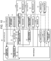
- FIG. 10 is a block diagram for illustrating a configuration of the speed control system. Description of parts having the same configurations as those of FIG. 3 is omitted.
- the image controller 301 outputs the print instruction to settle, in addition to the information of FIG. 3 , feed cassette information on one of the plurality of feed cassettes to be used.
- the print controller 303 drives the feed solenoid 309 or a feed solenoid 1000 corresponding to the feed cassette information so that the recording material P is fed and an image is formed.
- the size detector 310 checks the logic of the recording material width sensor 311 after a predetermined time period has elapsed from when the registration sensor 110 detects the leading edge of the recording material P to detect the width information on the recording material P, and stores the detection result into the storage (not shown) in association with (in relation with) the feed cassette from which the recording material P is fed. Accordingly, when the cassette presence/absence detector 312 gives a notification indicating recording material absence of the feed cassette 140 , the size detector 310 clears the width information on the recording material P associated with the feed cassette 140 .
- a second cassette presence/absence detector 1001 always monitors the logic of the second cassette presence/absence sensor 901 , and, when the logic changes from feed cassette presence to feed cassette absence, the second cassette presence/absence detector 1001 notifies the size detector 310 of the recording material absence of the feed cassette 900 . Then, the size detector 310 clears the width information on the recording material P associated with the feed cassette 900 .
- the size information on the recording material P can be managed for each of the plurality of feeding ports.
- FIG. 11 A and FIG. 11 B are judgment flow charts in the third embodiment.
- FIG. 11 A is a flow chart of the pre-start execution judgment portion 302 .
- the pre-start execution judgment portion 302 judges whether or not any of the feed cassettes have the recording material. That is, the pre-start execution judgment portion 302 judges, based on the detection results of the cassette presence/absence detector 312 and the second cassette presence/absence detector 1001 , whether or not any one or more of the feed cassettes have the recording material P. In a case in which the pre-start execution judgment portion 302 judges that none of the cassettes have the recording material or the feed cassette is absent in S 1100 , the pre-start execution judgment portion 302 advances the process to S 1101 .
- the pre-start execution judgment portion 302 judges not to execute the pre-start, and ends the processing. In a case in which the pre-start execution judgment portion 302 judges that any one or more of the feed cassettes have the recording material P in S 1100 , the pre-start execution judgment portion 302 advances the process to S 1102 .
- the pre-start execution judgment portion 302 judges whether or not there is a feed cassette of which a sheet size has not been measured by the size detector 310 (hereinafter referred to as “sheet size unmeasured feed cassette”). In a case in which the pre-start execution judgment portion 302 judges that there is a sheet size unmeasured feed cassette in S 1102 , the pre-start execution judgment portion 302 advances the process to S 1103 . In a case in which the pre-start execution judgment portion 302 judges that there is no sheet size unmeasured feed cassette in S 1102 , the pre-start execution judgment portion 302 advances the process to S 1104 . In S 1103 , the pre-start execution judgment portion 302 judges to execute the pre-start, and ends the processing.
- the pre-start execution judgment portion 302 judges whether or not the sheet size information for all measured (confirmed) feed cassettes is the narrow width.
- the pre-start execution judgment portion 302 judges that the sheet size information for all measured feed cassettes is the narrow width in S 1104 .
- the pre-start execution judgment portion 302 advances the process to S 101 .
- the pre-start execution judgment portion 302 judges not to execute the pre-start, and ends the processing.
- the pre-start execution judgment portion 302 advances the process to S 1103 .
- the pre-start execution judgment portion 302 judges to execute the pre-start, and ends the processing.
- FIG. 11 B is a flow chart of the printing speed judgment portion 308 .
- the same processes as those in the control flow chart of FIG. 4 B are denoted by the same step numbers (S 404 to S 410 , and S 412 ), and description thereof is omitted.
- the printing speed judgment portion 308 judges that the print side is the front side in S 409
- the printing speed judgment portion 308 performs the process of S 1105 . That is, in a case in which no forced low speed instruction is given from the image controller 301 , the type designation of the recording material P is plain paper or thin paper, a non-standard size is designated or the designated sheet size is wide width standard paper, and the print side is the front side, the following process is performed.
- the printing speed judgment portion 308 refers to the sheet size information of the feed cassette designated from the image controller 301 , and judges whether or not the sheet size has been measured by the size detector 310 . In a case in which the printing speed judgment portion 308 judges that the sheet size has not been measured in S 1105 , the printing speed judgment portion 308 advances the process to S 412 . In S 412 , the printing speed judgment portion 308 judges that the image forming speed is the first speed assuming that the recording material P having the wide width is set in the designated feed cassette, and ends the processing.
- the printing speed judgment portion 308 judges that the sheet size has been measured in S 1105 .
- the printing speed judgment portion 308 advances the process to S 1106 .
- the printing speed judgment portion 308 refers to the sheet size information of the designated feed cassette, and judges whether or not the sheet size information is the narrow width.
- the printing speed judgment portion 308 judges that the sheet size information is the wide width in S 1106 .
- the printing speed judgment portion 308 advances the process to S 412 .
- the printing speed judgment portion 308 judges that the image forming speed is the first speed, and ends the processing.
- the printing speed judgment portion 308 judges that the sheet size information is the narrow width in S 1106 .
- the printing speed judgment portion 308 advances the process to S 405 .
- the printing speed judgment portion 308 judges that the image forming speed is the second speed, and ends the processing.
- the recording material width detection mechanism judges the recording material width with respect to all of the feed cassettes by the recording material width sensor on the conveyance path.
- the feed cassette including the position sensor being the regulation plate of the feed cassette may be used, and the position sensor of the feed cassette may be used for the judgment of the sheet size of the feed cassette.
- the occurrence of the switching operation of the image forming speed is suppressed while the first print out time is reduced, thereby being capable of suppressing the increase of the first print out time and the progress of the life of the consumable item.
- the occurrence of the switching operation of the image forming speed is suppressed while the first print out time is reduced, thereby being capable of suppressing the increase of the first print out time and progress of the life of the consumable item.
Landscapes
- Physics & Mathematics (AREA)
- General Physics & Mathematics (AREA)
- Engineering & Computer Science (AREA)
- Microelectronics & Electronic Packaging (AREA)
- Control Or Security For Electrophotography (AREA)
- Sheets, Magazines, And Separation Thereof (AREA)
Abstract
Description
Claims (7)
Applications Claiming Priority (2)
| Application Number | Priority Date | Filing Date | Title |
|---|---|---|---|
| JP2020211243A JP7566615B2 (en) | 2020-12-21 | 2020-12-21 | Image forming device |
| JP2020-211243 | 2020-12-21 |
Publications (2)
| Publication Number | Publication Date |
|---|---|
| US20220197205A1 US20220197205A1 (en) | 2022-06-23 |
| US12085881B2 true US12085881B2 (en) | 2024-09-10 |
Family
ID=82023006
Family Applications (1)
| Application Number | Title | Priority Date | Filing Date |
|---|---|---|---|
| US17/556,797 Active US12085881B2 (en) | 2020-12-21 | 2021-12-20 | Image forming apparatus for conveying a recording material to perform an image forming operation |
Country Status (2)
| Country | Link |
|---|---|
| US (1) | US12085881B2 (en) |
| JP (1) | JP7566615B2 (en) |
Citations (7)
| Publication number | Priority date | Publication date | Assignee | Title |
|---|---|---|---|---|
| JP2006260185A (en) | 2005-03-17 | 2006-09-28 | Canon Inc | Image recording device |
| JP2009265286A (en) | 2008-04-24 | 2009-11-12 | Oki Data Corp | Image forming device and image forming method thereof |
| JP2010122702A (en) | 2010-01-12 | 2010-06-03 | Konica Minolta Business Technologies Inc | Image forming apparatus |
| US20100232818A1 (en) * | 2009-03-11 | 2010-09-16 | Hiroyuki Kunii | Fixing device, image forming apparatus incorporating same, and control method for fixing device |
| US20170115622A1 (en) * | 2015-10-27 | 2017-04-27 | Canon Kabushiki Kaisha | Image forming apparatus |
| JP2017223903A (en) | 2016-06-17 | 2017-12-21 | キヤノン株式会社 | Image forming apparatus |
| US20190196381A1 (en) * | 2017-12-22 | 2019-06-27 | Konica Minolta, Inc. | Image forming apparatus, and method for controlling the same |
Family Cites Families (3)
| Publication number | Priority date | Publication date | Assignee | Title |
|---|---|---|---|---|
| JP2002023576A (en) * | 2000-07-12 | 2002-01-23 | Sharp Corp | Image forming device |
| KR101405993B1 (en) * | 2007-08-06 | 2014-06-11 | 삼성전자주식회사 | Printing apparatus for reducing an early stage printing time and printing control methed thereof |
| JP2016215396A (en) * | 2015-05-14 | 2016-12-22 | キヤノンファインテック株式会社 | Image formation apparatus, control method and program |
-
2020
- 2020-12-21 JP JP2020211243A patent/JP7566615B2/en active Active
-
2021
- 2021-12-20 US US17/556,797 patent/US12085881B2/en active Active
Patent Citations (7)
| Publication number | Priority date | Publication date | Assignee | Title |
|---|---|---|---|---|
| JP2006260185A (en) | 2005-03-17 | 2006-09-28 | Canon Inc | Image recording device |
| JP2009265286A (en) | 2008-04-24 | 2009-11-12 | Oki Data Corp | Image forming device and image forming method thereof |
| US20100232818A1 (en) * | 2009-03-11 | 2010-09-16 | Hiroyuki Kunii | Fixing device, image forming apparatus incorporating same, and control method for fixing device |
| JP2010122702A (en) | 2010-01-12 | 2010-06-03 | Konica Minolta Business Technologies Inc | Image forming apparatus |
| US20170115622A1 (en) * | 2015-10-27 | 2017-04-27 | Canon Kabushiki Kaisha | Image forming apparatus |
| JP2017223903A (en) | 2016-06-17 | 2017-12-21 | キヤノン株式会社 | Image forming apparatus |
| US20190196381A1 (en) * | 2017-12-22 | 2019-06-27 | Konica Minolta, Inc. | Image forming apparatus, and method for controlling the same |
Also Published As
| Publication number | Publication date |
|---|---|
| JP2022097964A (en) | 2022-07-01 |
| US20220197205A1 (en) | 2022-06-23 |
| JP7566615B2 (en) | 2024-10-15 |
Similar Documents
| Publication | Publication Date | Title |
|---|---|---|
| US10065819B2 (en) | Image forming apparatus and feeding device | |
| US10372069B2 (en) | Image forming apparatus having a control portion capable of controlling a rotation speed of a pair of conveyance members | |
| US9701502B2 (en) | Image forming apparatus | |
| US8585038B2 (en) | Image-forming device changing stopping time of sheet-skew correction roller | |
| US12085881B2 (en) | Image forming apparatus for conveying a recording material to perform an image forming operation | |
| JP6743647B2 (en) | Image forming device | |
| CN119717427A (en) | Image forming device | |
| JP5790263B2 (en) | Image forming apparatus | |
| US10906762B2 (en) | Sheet conveyance apparatus and image forming apparatus | |
| JP2001354337A (en) | Sheet carrying device | |
| JP2000272781A (en) | Image forming device | |
| JP7476252B2 (en) | Image forming device | |
| JP7263755B2 (en) | Sheet conveying device and image recording device | |
| JP7625403B2 (en) | Image forming device | |
| JP2583329B2 (en) | Sheet feeding device | |
| JP2003167450A (en) | Image forming device | |
| JP6897631B2 (en) | Fixing device and image forming device | |
| JP4932327B2 (en) | Image forming apparatus | |
| JP2025017246A (en) | Sheet conveying device and image forming apparatus | |
| US20150338797A1 (en) | Image forming apparatus and temperature control method for fixing device in image forming apparatus | |
| JP5409574B2 (en) | Image forming apparatus | |
| CN120817469A (en) | Sheet feeding device and image forming apparatus | |
| JP2025000383A (en) | Image forming apparatus and method for controlling option paper feed device in image forming apparatus | |
| JPH0667481A (en) | Image forming device | |
| JP2006072208A (en) | Image forming apparatus |
Legal Events
| Date | Code | Title | Description |
|---|---|---|---|
| FEPP | Fee payment procedure |
Free format text: ENTITY STATUS SET TO UNDISCOUNTED (ORIGINAL EVENT CODE: BIG.); ENTITY STATUS OF PATENT OWNER: LARGE ENTITY |
|
| STPP | Information on status: patent application and granting procedure in general |
Free format text: DOCKETED NEW CASE - READY FOR EXAMINATION |
|
| AS | Assignment |
Owner name: CANON KABUSHIKI KAISHA, JAPAN Free format text: ASSIGNMENT OF ASSIGNORS INTEREST;ASSIGNOR:ISHIKAWA, SHIMPEI;REEL/FRAME:058837/0772 Effective date: 20211213 |
|
| STPP | Information on status: patent application and granting procedure in general |
Free format text: NON FINAL ACTION MAILED |
|
| STPP | Information on status: patent application and granting procedure in general |
Free format text: RESPONSE TO NON-FINAL OFFICE ACTION ENTERED AND FORWARDED TO EXAMINER |
|
| STPP | Information on status: patent application and granting procedure in general |
Free format text: FINAL REJECTION MAILED |
|
| STPP | Information on status: patent application and granting procedure in general |
Free format text: DOCKETED NEW CASE - READY FOR EXAMINATION |
|
| STPP | Information on status: patent application and granting procedure in general |
Free format text: NOTICE OF ALLOWANCE MAILED -- APPLICATION RECEIVED IN OFFICE OF PUBLICATIONS |
|
| ZAAA | Notice of allowance and fees due |
Free format text: ORIGINAL CODE: NOA |
|
| ZAAB | Notice of allowance mailed |
Free format text: ORIGINAL CODE: MN/=. |
|
| STPP | Information on status: patent application and granting procedure in general |
Free format text: NOTICE OF ALLOWANCE MAILED -- APPLICATION RECEIVED IN OFFICE OF PUBLICATIONS |
|
| STPP | Information on status: patent application and granting procedure in general |
Free format text: PUBLICATIONS -- ISSUE FEE PAYMENT VERIFIED |
|
| STCF | Information on status: patent grant |
Free format text: PATENTED CASE |