US12085339B2 - Apparatus for calcining secondary battery cathode material - Google Patents
Apparatus for calcining secondary battery cathode material Download PDFInfo
- Publication number
- US12085339B2 US12085339B2 US17/787,769 US202017787769A US12085339B2 US 12085339 B2 US12085339 B2 US 12085339B2 US 202017787769 A US202017787769 A US 202017787769A US 12085339 B2 US12085339 B2 US 12085339B2
- Authority
- US
- United States
- Prior art keywords
- space
- wall
- section
- cathode material
- temperature
- Prior art date
- Legal status (The legal status is an assumption and is not a legal conclusion. Google has not performed a legal analysis and makes no representation as to the accuracy of the status listed.)
- Active
Links
Images


Classifications
-
- F—MECHANICAL ENGINEERING; LIGHTING; HEATING; WEAPONS; BLASTING
- F27—FURNACES; KILNS; OVENS; RETORTS
- F27B—FURNACES, KILNS, OVENS OR RETORTS IN GENERAL; OPEN SINTERING OR LIKE APPARATUS
- F27B9/00—Furnaces through which the charge is moved mechanically, e.g. of tunnel type; Similar furnaces in which the charge moves by gravity
- F27B9/14—Furnaces through which the charge is moved mechanically, e.g. of tunnel type; Similar furnaces in which the charge moves by gravity characterised by the path of the charge during treatment; characterised by the means by which the charge is moved during treatment
- F27B9/20—Furnaces through which the charge is moved mechanically, e.g. of tunnel type; Similar furnaces in which the charge moves by gravity characterised by the path of the charge during treatment; characterised by the means by which the charge is moved during treatment the charge moving in a substantially straight path
- F27B9/24—Furnaces through which the charge is moved mechanically, e.g. of tunnel type; Similar furnaces in which the charge moves by gravity characterised by the path of the charge during treatment; characterised by the means by which the charge is moved during treatment the charge moving in a substantially straight path being carried by a conveyor
-
- B—PERFORMING OPERATIONS; TRANSPORTING
- B01—PHYSICAL OR CHEMICAL PROCESSES OR APPARATUS IN GENERAL
- B01J—CHEMICAL OR PHYSICAL PROCESSES, e.g. CATALYSIS OR COLLOID CHEMISTRY; THEIR RELEVANT APPARATUS
- B01J19/00—Chemical, physical or physico-chemical processes in general; Their relevant apparatus
- B01J19/0006—Controlling or regulating processes
-
- F—MECHANICAL ENGINEERING; LIGHTING; HEATING; WEAPONS; BLASTING
- F27—FURNACES; KILNS; OVENS; RETORTS
- F27B—FURNACES, KILNS, OVENS OR RETORTS IN GENERAL; OPEN SINTERING OR LIKE APPARATUS
- F27B9/00—Furnaces through which the charge is moved mechanically, e.g. of tunnel type; Similar furnaces in which the charge moves by gravity
- F27B9/14—Furnaces through which the charge is moved mechanically, e.g. of tunnel type; Similar furnaces in which the charge moves by gravity characterised by the path of the charge during treatment; characterised by the means by which the charge is moved during treatment
- F27B9/20—Furnaces through which the charge is moved mechanically, e.g. of tunnel type; Similar furnaces in which the charge moves by gravity characterised by the path of the charge during treatment; characterised by the means by which the charge is moved during treatment the charge moving in a substantially straight path
- F27B9/24—Furnaces through which the charge is moved mechanically, e.g. of tunnel type; Similar furnaces in which the charge moves by gravity characterised by the path of the charge during treatment; characterised by the means by which the charge is moved during treatment the charge moving in a substantially straight path being carried by a conveyor
- F27B9/2407—Furnaces through which the charge is moved mechanically, e.g. of tunnel type; Similar furnaces in which the charge moves by gravity characterised by the path of the charge during treatment; characterised by the means by which the charge is moved during treatment the charge moving in a substantially straight path being carried by a conveyor the conveyor being constituted by rollers (roller hearth furnace)
-
- F—MECHANICAL ENGINEERING; LIGHTING; HEATING; WEAPONS; BLASTING
- F27—FURNACES; KILNS; OVENS; RETORTS
- F27B—FURNACES, KILNS, OVENS OR RETORTS IN GENERAL; OPEN SINTERING OR LIKE APPARATUS
- F27B9/00—Furnaces through which the charge is moved mechanically, e.g. of tunnel type; Similar furnaces in which the charge moves by gravity
- F27B9/14—Furnaces through which the charge is moved mechanically, e.g. of tunnel type; Similar furnaces in which the charge moves by gravity characterised by the path of the charge during treatment; characterised by the means by which the charge is moved during treatment
- F27B9/20—Furnaces through which the charge is moved mechanically, e.g. of tunnel type; Similar furnaces in which the charge moves by gravity characterised by the path of the charge during treatment; characterised by the means by which the charge is moved during treatment the charge moving in a substantially straight path
- F27B9/26—Furnaces through which the charge is moved mechanically, e.g. of tunnel type; Similar furnaces in which the charge moves by gravity characterised by the path of the charge during treatment; characterised by the means by which the charge is moved during treatment the charge moving in a substantially straight path on or in trucks, sleds, or containers
-
- F—MECHANICAL ENGINEERING; LIGHTING; HEATING; WEAPONS; BLASTING
- F27—FURNACES; KILNS; OVENS; RETORTS
- F27B—FURNACES, KILNS, OVENS OR RETORTS IN GENERAL; OPEN SINTERING OR LIKE APPARATUS
- F27B9/00—Furnaces through which the charge is moved mechanically, e.g. of tunnel type; Similar furnaces in which the charge moves by gravity
- F27B9/30—Details, accessories or equipment specially adapted for furnaces of these types
- F27B9/3005—Details, accessories or equipment specially adapted for furnaces of these types arrangements for circulating gases
-
- F—MECHANICAL ENGINEERING; LIGHTING; HEATING; WEAPONS; BLASTING
- F27—FURNACES; KILNS; OVENS; RETORTS
- F27B—FURNACES, KILNS, OVENS OR RETORTS IN GENERAL; OPEN SINTERING OR LIKE APPARATUS
- F27B9/00—Furnaces through which the charge is moved mechanically, e.g. of tunnel type; Similar furnaces in which the charge moves by gravity
- F27B9/30—Details, accessories or equipment specially adapted for furnaces of these types
- F27B9/32—Casings
-
- F—MECHANICAL ENGINEERING; LIGHTING; HEATING; WEAPONS; BLASTING
- F27—FURNACES; KILNS; OVENS; RETORTS
- F27B—FURNACES, KILNS, OVENS OR RETORTS IN GENERAL; OPEN SINTERING OR LIKE APPARATUS
- F27B9/00—Furnaces through which the charge is moved mechanically, e.g. of tunnel type; Similar furnaces in which the charge moves by gravity
- F27B9/30—Details, accessories or equipment specially adapted for furnaces of these types
- F27B9/36—Arrangements of heating devices
-
- Y—GENERAL TAGGING OF NEW TECHNOLOGICAL DEVELOPMENTS; GENERAL TAGGING OF CROSS-SECTIONAL TECHNOLOGIES SPANNING OVER SEVERAL SECTIONS OF THE IPC; TECHNICAL SUBJECTS COVERED BY FORMER USPC CROSS-REFERENCE ART COLLECTIONS [XRACs] AND DIGESTS
- Y02—TECHNOLOGIES OR APPLICATIONS FOR MITIGATION OR ADAPTATION AGAINST CLIMATE CHANGE
- Y02E—REDUCTION OF GREENHOUSE GAS [GHG] EMISSIONS, RELATED TO ENERGY GENERATION, TRANSMISSION OR DISTRIBUTION
- Y02E60/00—Enabling technologies; Technologies with a potential or indirect contribution to GHG emissions mitigation
- Y02E60/10—Energy storage using batteries
Definitions
- the present disclosure relates to an apparatus for calcining a secondary battery cathode material.
- an apparatus for calcining a cathode material of a secondary battery calcines a sagger where a cathode material is accommodated in a calcination furnace at about 400 degrees to 1100 degrees according to characteristics of the material.
- aqueous vapor and carbon dioxide gas are generated from the cathode material stored in the sagger, and in the case of carbon dioxide gas, it is difficult to release to the outside of the sagger because of its molecular weight compared to oxygen or air used to control the calcination furnace atmosphere.
- Carbon dioxide gas remaining inside the sagger causes a chemical reaction with a lithium oxide on a positive active material surface calcinated from the cathode material to produce lithium carbonate.
- a conventional apparatus for calcining a secondary battery cathode material discharges aqueous vapor and carbon dioxide gas generated from the cathode material accommodated in the sagger to the outside of the sagger, and at the same time, for the calcination reaction, gases such as oxygen and air are supplied to the lower, upper, and side of the calcination space where the sagger is positioned.
- the cross-section of the window of the sagger through which gas inflows from the outside of the sagger to the inside of the sagger is very small compared to the cross-section of the calcination space where the sagger is positioned, and thus there is a problem that only a very small amount of the entire flow of gas passing through the cross-section of the space inflows into the inside of the sagger.
- An embodiment is to provide an apparatus for calcining a secondary battery cathode material, which improves the carbon dioxide gas emission from the inside of the sagger by increasing the flow rate of gas flowing into the sagger accommodating the secondary battery cathode material, while simultaneously improving the calcination reaction of the secondary battery cathode material accommodated in the sagger.
- One aspect provides an apparatus for calcining a secondary battery cathode material, including: a calcination furnace including an inner space that includes a temperature rising space, a temperature maintaining space, and a cooling space that are sequentially communicated with each other; a plurality of rollers that are disposed along the inner space and transport the sagger accommodating the cathode material from the temperature rising space to the cooling space through the temperature maintaining space; a plurality of heaters disposed along the inner space with the plurality of rollers interposed therebetween; a plurality of gas feeding parts connected to the inner space and supplying gas to the inner space; and a plurality of exhaust parts connected to the inner space and exhausting gas from the inner space, wherein a cross-section of the temperature maintaining space is smaller than a cross-section of the temperature rising space and a cross-section of the cooling space.
- the first inner wall of the calcination furnace forming the temperature maintaining space may be closer to the plurality of rollers compared to the second inner wall of the calcination furnace forming the temperature rising space and the third inner wall of the calcination furnace forming the cooling space.
- the plurality of heaters may include: first heaters positioned inside the first inner wall; second heaters positioned in the temperature rising space while being spaced apart from the second inner wall; and third heaters positioned in the cooling space while being spaced apart from the third inner wall.
- the first heaters may have a smaller capacity than the second heaters and the third heaters.
- the apparatus for calcining the secondary battery cathode material may further include: a first partitioning wall that extends in a vertical direction from the second inner wall of the calcination furnace; and a second partitioning wall that extends in the vertical direction from the third inner wall of the calcination furnace, wherein an end of the first partitioning wall and an end of the second partitioning wall may be positioned on the horizontal line with the second inner wall.
- the plurality of gas feeding parts may include: a first gas feeding part connected to a lower portion of the temperature rising space; a second gas feeding part connected to a lower portion of the temperature maintaining space; and a third gas feeding part connected to a lower portion of the cooling space.
- the plurality of exhaust parts may include: a first exhaust part connected with an upper portion of the temperature rising space; and a second exhaust part connected with an upper portion of the cooling space.
- the apparatus for calcining the secondary battery cathode material which improves the carbon dioxide gas emission from the inside of the sagger by increasing the flow rate of gas flowing into the sagger accommodating the secondary battery cathode material, while simultaneously improving the calcination reaction of the secondary battery cathode material accommodated in the sagger, can be provided.
- FIG. 1 shows an apparatus for calcining a secondary battery cathode material according to an embodiment.
- FIG. 2 shows a cross-section of a comparative example and a cross-section of an experimental example.
- FIG. 3 is a table that shows an experiment results of the cross-section of the comparative example and the cross-section of the experimental example of FIG. 2 .
- FIG. 1 an apparatus for calcining a secondary battery cathode material according to an embodiment will be described.
- FIG. 1 shows an apparatus for calcining a secondary battery cathode material according to an embodiment.
- the apparatus for calcining the secondary battery cathode material includes a temperature rising section A 1 , a temperature maintaining section A 2 , and a cooling section A 3 .
- the temperature rising section A 1 is a section in which the temperature is raised to a predetermined temperature (for example, 400 degrees to 1100 degrees) according to the characteristics of the secondary battery cathode material accommodated in the sagger SA.
- the temperature maintaining section A 2 is a section to maintain the predetermined temperature.
- the cooling section A 3 is a section cooled from a predetermined temperature.
- the apparatus for calcining the secondary battery cathode material includes a calcination furnace 100 that forms the temperature rising section A 1 , the temperature maintaining section A 2 , the cooling section A 3 , a plurality of rollers 200 , a plurality of heaters 300 , a plurality of gas feeding parts 400 , and a plurality of exhaust parts 500 .
- the calcination furnace 100 includes an inner space 110 , a first inner wall 120 , a second inner wall 130 , a third inner wall 140 , a first partitioning wall 150 , and a second partitioning wall 160 .
- the inner space 110 is a space in which the sagger SA in which the cathode material is accommodated is moved in one direction, and includes a temperature rising space S 1 , a temperature maintaining space S 2 , and a cooling space S 3 that sequentially communicate with each other along the one direction.
- the temperature rising space S 1 is a space corresponding to the temperature rising section A 1 .
- the cross-section of the temperature rising space S 1 is larger than the cross-section of the temperature maintaining space S 2 .
- the temperature maintaining space S 2 communicates with the temperature rising space S 1 and corresponds to the temperature maintaining section A 2 .
- the cross-section of the temperature maintaining space S 2 is smaller than the cross-section of the temperature rising space S 1 and the cross-section of the cooling space S 3 .
- the cooling space S 3 communicates with the temperature maintaining space S 2 and corresponds to the cooling section A 3 .
- the cross-section of the cooling space S 3 is larger than that of the temperature maintaining space S 2 .
- the first inner wall 120 forms the temperature maintaining space S 2 .
- the first inner wall 120 is an inner wall of the lower wall, upper wall, and sidewall forming the temperature maintaining space S 2 .
- a first height L 1 of the temperature maintaining space S 2 formed by the first inner wall 120 is shorter than a second height L 2 of the temperature rising space S 1 formed by the second inner wall 130 and a third height L 3 of the cooling space S 3 formed by the third inner wall 140 .
- the first inner wall 120 is positioned closer to the rollers 200 compared to the second inner wall 130 and third inner wall 140 .
- the second inner wall 130 forms the temperature rising space S 1 .
- the second inner wall 130 is an inner wall of the lower wall, upper wall, and sidewall forming the temperature rising space S 1 .
- the second height L 2 of the temperature rising space S 1 formed by the second inner wall 130 is longer than the first height L 1 of the temperature maintaining space S 2 formed by the first inner wall 120 .
- the second inner wall 130 is positioned farther from the rollers 200 compared to the first inner wall 120 .
- the third inner wall 140 forms the cooling space S 3 .
- the third inner wall 140 is an inner wall of the lower wall, upper wall, and sidewall forming the cooling space S 3 .
- the third height L 3 of the cooling space S 3 formed by the third inner wall 140 is longer than the first height L 1 of the temperature maintaining space S 2 formed by the first inner wall 120 .
- the third inner wall 140 is positioned farther from the rollers 200 compared to the first inner wall 120 .
- the first partitioning wall 150 extends from the second inner wall 130 in the vertical direction.
- the first partitioning wall 150 partitions the temperature rising space S 1 , and the temperature may increase along the space partitioned by the first partitioning wall 150 .
- the second partitioning wall 160 extends from the third inner wall 140 in the vertical direction.
- the second partitioning wall 160 partitions the cooling space S 3 , and the temperature may decrease along the space partitioned by the second partitioning wall 160 .
- An end of the first partitioning wall 150 and an end of the second partitioning wall 160 may be positioned on an imaginary horizontal line with the second inner wall 130 . That is, the first partitioning wall 150 , the second inner wall 130 , and the second partitioning wall 160 may be positioned on the same horizontal line.
- a plurality of rollers 200 are disposed in one direction along the inner space 110 of the calcination furnace 100 .
- the plurality of rollers 200 transfer the sagger SA containing the cathode material from the temperature rising space S 1 inside the calcination furnace 100 to the cooling space S 3 through the temperature maintaining space S 2 .
- the plurality of heaters 300 includes upper heaters and lower heaters disposed in one direction along the inner space 110 with the plurality of rollers 200 interposed therebetween.
- the plurality of heaters 300 include first heaters 310 , second heaters 320 , and third heaters 330 .
- the first heaters 310 are positioned inside the first inner wall 120 with the temperature maintaining space S 2 interposed therebetween.
- the first heaters 310 have a smaller capacity than the second heaters 320 and the third heaters 330 .
- the second heaters 320 are spaced apart from the second inner wall 130 and positioned in the temperature rising space S 1 .
- the third heaters 330 are spaced apart from the third inner wall 140 and positioned in the cooling space S 3 .
- a plurality of gas feeding parts 400 are connected to the inner space 110 and supply gas GA to the inner space 110 .
- the gas GA supplied by the gas feeding parts 400 may include air and oxygen gas, but is not limited thereto.
- the plurality of gas feeding parts 400 includes a first gas feeding part 410 , a second gas feeding part 420 , and a third gas feeding part 430 .
- the first gas feeding part 410 is connected to a lower part of the temperature rising space S 1 and supplies the gas GA to the temperature rising space S 1 .
- the gas GA supplied from the first gas feeding part 410 to the temperature rising space S 1 may be selectively exhausted to the first exhaust part 510 or the second exhaust part 520 through the temperature rising space S 1 , the temperature maintaining space S 2 , and the cooling space S 3 .
- the second gas feeding part 420 is connected to a lower part of the temperature maintaining space S 2 and supplies the gas GA to the temperature maintaining space S 2 .
- the gas GA supplied from the second gas feeding part 420 to the temperature maintaining space S 2 may be selectively exhausted to the first exhaust part 510 or the second exhaust part 520 through the temperature rising space S 1 , the temperature maintaining space S 2 , and the cooling space S 3 .
- the third gas feeding part 430 is connected to a lower part of the cooling space S 3 to supply the gas GA to the cooling space S 3 .
- the gas GA supplied to the cooling space S 3 from the third gas feeding part 430 may be selectively exhausted to the first exhaust part 510 or the second exhaust part 520 through the temperature rising space S 1 , the temperature maintaining space S 2 , and the cooling space S 3 .
- a plurality of exhaust parts 500 are connected to the inner space 110 and exhaust the gas GA from the inner space 110 .
- the gas GA exhausted by the exhaust parts 500 may further include carbon dioxide gas and aqueous vapor discharged from the sagger SA in addition to the air and oxygen gas supplied by the gas feeding parts 400 , but is not limited thereto.
- the plurality of exhaust parts 500 includes a first exhaust part 510 and a second exhaust part 520 .
- the first exhaust part 510 is connected to an upper part of the temperature rising space S 1 to exhaust the gas GA from the temperature rising space S 1 .
- the second exhaust part 520 is connected to an upper part of the cooling space S 3 to exhaust the gas GA from the cooling space S 3 .
- the flow rate of gas GA inflowing from the outside of the sagger SA to the inside of the sagger SA in the temperature maintaining space S 2 is increased compared to the cooling space S 3 and the temperature rising space S 1 such that the carbon dioxide gas emission from the inside of the sagger SA is improved and simultaneously the calcination reaction of the secondary battery cathode material housed in the sagger SA is improved.
- Inventors of the present invention determined whether it is effective to reduce the cross-section of the inner space 110 of which section of the temperature rising section A 1 , temperature maintaining section A 2 , and cooling section A 3 included in the apparatus for calcining the secondary battery cathode material. As a result of examining the calcination reaction of the cathode material accommodated in the sagger SA, it was confirmed that most of the carbon dioxide gas generated from the cathode material was generated at the temperature rising section A 1 , and the carbon dioxide gas generation decreased significantly from the temperature maintaining section A 2 .
- the cross-section of the temperature maintaining space S 2 corresponding to the temperature maintaining section A 2 is smaller than that of the temperature rising space S 1 and the cross-section of the cooling space S 3 in order to improve carbon dioxide gas emission from inside of the sagger SA.
- the inventors of the present invention determined that when the first inner wall 120 of the calcination furnace 100 is positioned on the same horizontal line as the first partitioning wall 150 and the second partitioning wall 160 to make the cross-section of the temperature maintaining space S 2 smaller than the cross-section of the temperature rising space S 1 and the cross-section of the cooling space S 3 , the first heater 310 could not be positioned in the temperature maintaining space S 2 of the calcination furnace 100 such that it may not be easy to maintain the temperature of the temperature maintaining space S 2 .
- the apparatus for calcining the secondary battery cathode material according to the embodiment, even though the cross-section of the temperature maintaining space S 2 is smaller than the cross-section of the temperature rising space S 1 and the cross-section of the cooling space S 3 , the first heater 310 with a small capacity is positioned inside the first inner wall 120 that forms the temperature maintaining space S 2 , and thus it is possible to maintain the temperature of the temperature maintaining space S 2 .
- the first heater 310 which has a smaller capacity compared to the second heater 320 and the third heater 330 , is positioned inside the first inner wall 120 such that the cross-section of the temperature maintaining space S 2 can be reduced to the maximum, thereby increasing the flow rate of gas flowing into the sagger SA in the temperature maintaining space S 2 to the maximum.
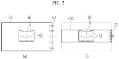
- FIG. 2 shows a cross-section according to a comparative example and a cross-section according to an experimental example.
- A) of FIG. 2 shows a cross-section according to a comparative example
- B) of FIG. 2 shows a cross-section according to an experimental example.
- the cross-section CS 1 which is a comparative example shown in (A) of FIG. 2 shows the cross-section of the temperature maintaining space that is the same as the cross-section of the temperature rising space and the cross-section of the cooling space.
- the cross-section CS 2 which is an experimental embodiment shown in (B) of FIG. 2 shows the cross-section of the temperature maintaining space with a small cross-section compared to the cross-section of the temperature rising space and cooling space.
- the cross-section according to the experimental example may represent the cross-section of the temperature maintaining space when the first inner wall forming the temperature maintaining space is positioned on the same horizontal line as the end of the first partitioning wall and the end of the second partitioning wall.
- the case of inflow of gas GA of the same flow rate to the cross-section CS 1 of the comparative example and the cross-section CS 2 of the experimental example was calculated through thermal fluid computational analysis, and a ratio of gas flow rates passing through the cross-section of the window WI on the side of the sagger SA was compared.
- concentration of the exhaust gas CO 2 that affects the calcination reaction of the cathode material accommodate in the sagger SA by the difference in the inflow gas flow rate was also compared.
- FIG. 3 is a table that shows a result of the experiment of the cross-section according to the comparative example the cross-section according to the experimental example.
- the flow analysis result shows that, in the cross-section of the comparative example, the area of the window on the side of the sagger is only 4.25% of the entire area, and the flow rate inflow to the sagger compared to the total supply flow rate is 3.2%.
- the apparatus for calcining the secondary battery cathode material which improves the carbon dioxide gas emission from the inside of the sagger by increasing the flow rate of gas flowing into the sagger accommodating the secondary battery cathode material, while simultaneously improving the calcination reaction of the secondary battery cathode material accommodated in the sagger, is provided.
- a cathode material loading amount can be increased (increased production), or the same calcination reaction can be performed with a smaller supply air flow rate for the same cathode material loading amount (reducing operating costs) such that the apparatus for calcining the secondary battery cathode material can lower the production cost of the cathode material.
Landscapes
- Engineering & Computer Science (AREA)
- Mechanical Engineering (AREA)
- General Engineering & Computer Science (AREA)
- Chemical & Material Sciences (AREA)
- Organic Chemistry (AREA)
- Chemical Kinetics & Catalysis (AREA)
- Battery Electrode And Active Subsutance (AREA)
- Tunnel Furnaces (AREA)
- Furnace Details (AREA)
Abstract
Description
Claims (4)
Applications Claiming Priority (3)
| Application Number | Priority Date | Filing Date | Title |
|---|---|---|---|
| KR10-2019-0171749 | 2019-12-20 | ||
| KR1020190171749A KR102368360B1 (en) | 2019-12-20 | 2019-12-20 | Apparatus for firing cathode material of secondary battery |
| PCT/KR2020/017412 WO2021125629A1 (en) | 2019-12-20 | 2020-12-01 | Apparatus for calcining secondary battery cathode material |
Publications (2)
| Publication Number | Publication Date |
|---|---|
| US20230074546A1 US20230074546A1 (en) | 2023-03-09 |
| US12085339B2 true US12085339B2 (en) | 2024-09-10 |
Family
ID=76476776
Family Applications (1)
| Application Number | Title | Priority Date | Filing Date |
|---|---|---|---|
| US17/787,769 Active US12085339B2 (en) | 2019-12-20 | 2020-12-01 | Apparatus for calcining secondary battery cathode material |
Country Status (6)
| Country | Link |
|---|---|
| US (1) | US12085339B2 (en) |
| EP (1) | EP4080149A4 (en) |
| JP (1) | JP7340701B2 (en) |
| KR (1) | KR102368360B1 (en) |
| CN (1) | CN114846288B (en) |
| WO (1) | WO2021125629A1 (en) |
Cited By (1)
| Publication number | Priority date | Publication date | Assignee | Title |
|---|---|---|---|---|
| US20240159466A1 (en) * | 2022-11-11 | 2024-05-16 | Hanwha Corporation | Heat treatment apparatus for manufacturing active material for secondary battery |
Families Citing this family (3)
| Publication number | Priority date | Publication date | Assignee | Title |
|---|---|---|---|---|
| KR102368360B1 (en) | 2019-12-20 | 2022-02-25 | 주식회사 포스코 | Apparatus for firing cathode material of secondary battery |
| KR20230088556A (en) * | 2021-12-10 | 2023-06-20 | 포스코홀딩스 주식회사 | Apparatus for firing cathode material of secondary battery |
| KR20250052087A (en) * | 2023-10-11 | 2025-04-18 | 포스코홀딩스 주식회사 | Apparatus for firing cathode material of secondary battery |
Citations (14)
| Publication number | Priority date | Publication date | Assignee | Title |
|---|---|---|---|---|
| US20080008976A1 (en) | 2006-07-10 | 2008-01-10 | Fujitsu Hitachi Plasma Display Limited | Heat treatment apparatus |
| JP2010216737A (en) | 2009-03-17 | 2010-09-30 | Tdk Corp | Continuous baking furnace and manufacturing system |
| WO2012025818A1 (en) | 2010-08-26 | 2012-03-01 | Panasonic Corporation | Wiring device |
| WO2012025819A1 (en) | 2010-08-26 | 2012-03-01 | Centrotherm Photovoltaics Ag | Continuous furnace |
| JP2013160423A (en) | 2012-02-03 | 2013-08-19 | Panasonic Corp | Continuous heat treatment apparatus |
| JP2014145566A (en) * | 2013-01-30 | 2014-08-14 | Kyocera Corp | Treatment furnace and method for manufacturing sintered object |
| JP2015064189A (en) | 2013-08-26 | 2015-04-09 | 日本碍子株式会社 | Heat treatment furnace and heat treatment method |
| KR20150039651A (en) | 2013-10-02 | 2015-04-13 | 주식회사 한화 | Roller hearth type kiln |
| KR20160115495A (en) | 2015-03-27 | 2016-10-06 | 한밭대학교 산학협력단 | Apparatus and method for detecting and converting the signal of HDMI and DVI to Displayport signal |
| KR20180074127A (en) | 2016-12-23 | 2018-07-03 | 주식회사 포스코 | Gasinlet method of furnace for secondary battery cathode and this apparatus |
| JP2018169137A (en) | 2017-03-30 | 2018-11-01 | 日本碍子株式会社 | Heat treatment furnace |
| WO2019107651A1 (en) * | 2017-12-01 | 2019-06-06 | 주식회사 포스코 | Secondary battery positive electrode material sintering apparatus and sintering method |
| KR101993209B1 (en) | 2018-05-25 | 2019-06-27 | 주식회사 한화 | Heat treatment kiln for fabricating cathode active material |
| KR20210079695A (en) | 2019-12-20 | 2021-06-30 | 주식회사 포스코 | Apparatus for firing cathode material of secondary battery |
Family Cites Families (2)
| Publication number | Priority date | Publication date | Assignee | Title |
|---|---|---|---|---|
| KR102152888B1 (en) * | 2013-12-31 | 2020-09-07 | 삼성에스디아이 주식회사 | Method for preparing of positive active material for lithium secondary battery and positive active material for lithium secondary battery prepared by same |
| CN209181504U (en) * | 2018-09-13 | 2019-07-30 | 广东邦普循环科技有限公司 | A kind of anode material of lithium battery high-temperature roller kiln |
-
2019
- 2019-12-20 KR KR1020190171749A patent/KR102368360B1/en active Active
-
2020
- 2020-12-01 WO PCT/KR2020/017412 patent/WO2021125629A1/en not_active Ceased
- 2020-12-01 US US17/787,769 patent/US12085339B2/en active Active
- 2020-12-01 CN CN202080088842.0A patent/CN114846288B/en active Active
- 2020-12-01 JP JP2022538290A patent/JP7340701B2/en active Active
- 2020-12-01 EP EP20903138.4A patent/EP4080149A4/en active Pending
Patent Citations (16)
| Publication number | Priority date | Publication date | Assignee | Title |
|---|---|---|---|---|
| US20080008976A1 (en) | 2006-07-10 | 2008-01-10 | Fujitsu Hitachi Plasma Display Limited | Heat treatment apparatus |
| JP2010216737A (en) | 2009-03-17 | 2010-09-30 | Tdk Corp | Continuous baking furnace and manufacturing system |
| WO2012025818A1 (en) | 2010-08-26 | 2012-03-01 | Panasonic Corporation | Wiring device |
| WO2012025819A1 (en) | 2010-08-26 | 2012-03-01 | Centrotherm Photovoltaics Ag | Continuous furnace |
| JP2013160423A (en) | 2012-02-03 | 2013-08-19 | Panasonic Corp | Continuous heat treatment apparatus |
| JP2014145566A (en) * | 2013-01-30 | 2014-08-14 | Kyocera Corp | Treatment furnace and method for manufacturing sintered object |
| JP2015064189A (en) | 2013-08-26 | 2015-04-09 | 日本碍子株式会社 | Heat treatment furnace and heat treatment method |
| KR20150039651A (en) | 2013-10-02 | 2015-04-13 | 주식회사 한화 | Roller hearth type kiln |
| KR20160115495A (en) | 2015-03-27 | 2016-10-06 | 한밭대학교 산학협력단 | Apparatus and method for detecting and converting the signal of HDMI and DVI to Displayport signal |
| KR20180074127A (en) | 2016-12-23 | 2018-07-03 | 주식회사 포스코 | Gasinlet method of furnace for secondary battery cathode and this apparatus |
| JP2018169137A (en) | 2017-03-30 | 2018-11-01 | 日本碍子株式会社 | Heat treatment furnace |
| WO2019107651A1 (en) * | 2017-12-01 | 2019-06-06 | 주식회사 포스코 | Secondary battery positive electrode material sintering apparatus and sintering method |
| KR20190064850A (en) | 2017-12-01 | 2019-06-11 | 주식회사 포스코 | Apparatus and method for heating secondary battery cathode material |
| JP2021504912A (en) | 2017-12-01 | 2021-02-15 | ポスコPosco | Firing device and firing method for secondary battery positive electrode material |
| KR101993209B1 (en) | 2018-05-25 | 2019-06-27 | 주식회사 한화 | Heat treatment kiln for fabricating cathode active material |
| KR20210079695A (en) | 2019-12-20 | 2021-06-30 | 주식회사 포스코 | Apparatus for firing cathode material of secondary battery |
Non-Patent Citations (7)
| Title |
|---|
| Extended European Search Report issued Jun. 14, 2023 in European Application No. 20903138.4. |
| International Search Report for PCT/KR2020/017412, dated Mar. 11, 2021. |
| JP-2014145566-A English translation (Year: 2014). * |
| Notice of Allowance issued Aug. 1, 2023 in Japanese Application No. 2022-538290. |
| Thermal 6 Corporation, Temperature vs Heat Loss In a Heater (Year: 2019). * |
| WO-2019107651-A1 English translation (Year: 2019). * |
| Written Opinion for PCT/KR2020/017412, dated Mar. 11, 2021. |
Cited By (1)
| Publication number | Priority date | Publication date | Assignee | Title |
|---|---|---|---|---|
| US20240159466A1 (en) * | 2022-11-11 | 2024-05-16 | Hanwha Corporation | Heat treatment apparatus for manufacturing active material for secondary battery |
Also Published As
| Publication number | Publication date |
|---|---|
| JP2023507663A (en) | 2023-02-24 |
| KR20210079695A (en) | 2021-06-30 |
| EP4080149A1 (en) | 2022-10-26 |
| US20230074546A1 (en) | 2023-03-09 |
| KR102368360B1 (en) | 2022-02-25 |
| EP4080149A4 (en) | 2023-07-12 |
| WO2021125629A1 (en) | 2021-06-24 |
| CN114846288B (en) | 2026-03-17 |
| CN114846288A (en) | 2022-08-02 |
| JP7340701B2 (en) | 2023-09-07 |
Similar Documents
| Publication | Publication Date | Title |
|---|---|---|
| US12085339B2 (en) | Apparatus for calcining secondary battery cathode material | |
| CN114829860B (en) | Vertical secondary battery positive electrode material calcining device | |
| US20220065534A1 (en) | Furnace for producing secondary battery cathode material and method for firing secondary battery cathode material | |
| JP7629995B2 (en) | Vertical type cathode material baking equipment for secondary batteries | |
| US20210254211A1 (en) | Substrate processing apparatus | |
| KR102831930B1 (en) | Continuous kiln and heat treatment or thermochemical treatment method | |
| EP4446681A1 (en) | Apparatus for firing cathode material of secondary battery | |
| CN112414112B (en) | A continuous kiln and heat treatment method | |
| CN217423963U (en) | Kiln for producing lithium battery anode material | |
| CN213873745U (en) | Continuous kiln | |
| CN215447446U (en) | Air inlet and exhaust system of lithium ion battery anode material multilayer multi-column atmosphere furnace | |
| JP2021162246A (en) | Continuous burning furnace | |
| US20240159466A1 (en) | Heat treatment apparatus for manufacturing active material for secondary battery | |
| US20240151469A1 (en) | Heat treatment apparatus for manufacturing active material for secondary battery | |
| KR102897367B1 (en) | Heat treatment apparatus for fabricating active material for secondary battery | |
| KR20260018477A (en) | Apparatus for firing cathode material of secondary battery | |
| CN218410751U (en) | Roller kiln | |
| KR20260046570A (en) | A furnace conducting cooling using greenhouse gases | |
| KR20260055789A (en) | Calcination furnace for manufacturing cathode material | |
| KR20240094760A (en) | Firing system for electrode material | |
| US20110236775A1 (en) | Fuel Cell System |
Legal Events
| Date | Code | Title | Description |
|---|---|---|---|
| AS | Assignment |
Owner name: POSCO CHEMICAL CO., LTD, KOREA, REPUBLIC OF Free format text: ASSIGNMENT OF ASSIGNORS INTEREST;ASSIGNORS:YANG, CHOONGMO;JUNG, KEEYOUNG;PARK, YOONCHEOL;AND OTHERS;REEL/FRAME:060264/0083 Effective date: 20220525 Owner name: RESEARCH INSTITUTE OF INDUSTRIAL SCIENCE & TECHNOLOGY, KOREA, REPUBLIC OF Free format text: ASSIGNMENT OF ASSIGNORS INTEREST;ASSIGNORS:YANG, CHOONGMO;JUNG, KEEYOUNG;PARK, YOONCHEOL;AND OTHERS;REEL/FRAME:060264/0083 Effective date: 20220525 Owner name: POSCO, KOREA, REPUBLIC OF Free format text: ASSIGNMENT OF ASSIGNORS INTEREST;ASSIGNORS:YANG, CHOONGMO;JUNG, KEEYOUNG;PARK, YOONCHEOL;AND OTHERS;REEL/FRAME:060264/0083 Effective date: 20220525 |
|
| FEPP | Fee payment procedure |
Free format text: ENTITY STATUS SET TO UNDISCOUNTED (ORIGINAL EVENT CODE: BIG.); ENTITY STATUS OF PATENT OWNER: LARGE ENTITY |
|
| STPP | Information on status: patent application and granting procedure in general |
Free format text: DOCKETED NEW CASE - READY FOR EXAMINATION |
|
| STPP | Information on status: patent application and granting procedure in general |
Free format text: NON FINAL ACTION MAILED |
|
| STPP | Information on status: patent application and granting procedure in general |
Free format text: FINAL REJECTION MAILED |
|
| STPP | Information on status: patent application and granting procedure in general |
Free format text: DOCKETED NEW CASE - READY FOR EXAMINATION |
|
| STPP | Information on status: patent application and granting procedure in general |
Free format text: NON FINAL ACTION MAILED |
|
| STPP | Information on status: patent application and granting procedure in general |
Free format text: RESPONSE TO NON-FINAL OFFICE ACTION ENTERED AND FORWARDED TO EXAMINER |
|
| STPP | Information on status: patent application and granting procedure in general |
Free format text: FINAL REJECTION MAILED |
|
| STPP | Information on status: patent application and granting procedure in general |
Free format text: DOCKETED NEW CASE - READY FOR EXAMINATION |
|
| STPP | Information on status: patent application and granting procedure in general |
Free format text: NOTICE OF ALLOWANCE MAILED -- APPLICATION RECEIVED IN OFFICE OF PUBLICATIONS |
|
| STPP | Information on status: patent application and granting procedure in general |
Free format text: PUBLICATIONS -- ISSUE FEE PAYMENT VERIFIED |
|
| STCF | Information on status: patent grant |
Free format text: PATENTED CASE |