US12084965B2 - Acoustic telemetry tool for high mechanical loading - Google Patents
Acoustic telemetry tool for high mechanical loading Download PDFInfo
- Publication number
- US12084965B2 US12084965B2 US17/728,009 US202217728009A US12084965B2 US 12084965 B2 US12084965 B2 US 12084965B2 US 202217728009 A US202217728009 A US 202217728009A US 12084965 B2 US12084965 B2 US 12084965B2
- Authority
- US
- United States
- Prior art keywords
- acoustic telemetry
- inner mandrel
- acoustic
- connectors
- telemetry tool
- Prior art date
- Legal status (The legal status is an assumption and is not a legal conclusion. Google has not performed a legal analysis and makes no representation as to the accuracy of the status listed.)
- Active, expires
Links
- 238000004891 communication Methods 0.000 claims description 11
- 230000000712 assembly Effects 0.000 abstract description 11
- 238000000429 assembly Methods 0.000 abstract description 11
- 238000000034 method Methods 0.000 description 15
- 230000036316 preload Effects 0.000 description 6
- 125000006850 spacer group Chemical group 0.000 description 5
- 241000282472 Canis lupus familiaris Species 0.000 description 4
- 230000006835 compression Effects 0.000 description 3
- 238000007906 compression Methods 0.000 description 3
- 238000012545 processing Methods 0.000 description 2
- 238000003860 storage Methods 0.000 description 2
- 238000006467 substitution reaction Methods 0.000 description 2
- 238000007792 addition Methods 0.000 description 1
- 238000005452 bending Methods 0.000 description 1
- 230000009286 beneficial effect Effects 0.000 description 1
- 239000004568 cement Substances 0.000 description 1
- 238000012217 deletion Methods 0.000 description 1
- 230000037430 deletion Effects 0.000 description 1
- 238000005553 drilling Methods 0.000 description 1
- 230000006870 function Effects 0.000 description 1
- 238000002347 injection Methods 0.000 description 1
- 239000007924 injection Substances 0.000 description 1
- 239000007788 liquid Substances 0.000 description 1
- 238000004519 manufacturing process Methods 0.000 description 1
- 238000003801 milling Methods 0.000 description 1
- 238000012986 modification Methods 0.000 description 1
- 230000004048 modification Effects 0.000 description 1
- 230000003287 optical effect Effects 0.000 description 1
- 239000012858 resilient material Substances 0.000 description 1
- 239000007787 solid Substances 0.000 description 1
- 230000000638 stimulation Effects 0.000 description 1
- 238000012360 testing method Methods 0.000 description 1
- 238000003466 welding Methods 0.000 description 1
Images


Classifications
-
- E—FIXED CONSTRUCTIONS
- E21—EARTH OR ROCK DRILLING; MINING
- E21B—EARTH OR ROCK DRILLING; OBTAINING OIL, GAS, WATER, SOLUBLE OR MELTABLE MATERIALS OR A SLURRY OF MINERALS FROM WELLS
- E21B47/00—Survey of boreholes or wells
- E21B47/12—Means for transmitting measuring-signals or control signals from the well to the surface, or from the surface to the well, e.g. for logging while drilling
- E21B47/14—Means for transmitting measuring-signals or control signals from the well to the surface, or from the surface to the well, e.g. for logging while drilling using acoustic waves
- E21B47/16—Means for transmitting measuring-signals or control signals from the well to the surface, or from the surface to the well, e.g. for logging while drilling using acoustic waves through the drill string or casing, e.g. by torsional acoustic waves
-
- E—FIXED CONSTRUCTIONS
- E21—EARTH OR ROCK DRILLING; MINING
- E21B—EARTH OR ROCK DRILLING; OBTAINING OIL, GAS, WATER, SOLUBLE OR MELTABLE MATERIALS OR A SLURRY OF MINERALS FROM WELLS
- E21B17/00—Drilling rods or pipes; Flexible drill strings; Kellies; Drill collars; Sucker rods; Cables; Casings; Tubings
- E21B17/02—Couplings; joints
- E21B17/04—Couplings; joints between rod or the like and bit or between rod and rod or the like
- E21B17/042—Threaded
-
- E—FIXED CONSTRUCTIONS
- E21—EARTH OR ROCK DRILLING; MINING
- E21B—EARTH OR ROCK DRILLING; OBTAINING OIL, GAS, WATER, SOLUBLE OR MELTABLE MATERIALS OR A SLURRY OF MINERALS FROM WELLS
- E21B17/00—Drilling rods or pipes; Flexible drill strings; Kellies; Drill collars; Sucker rods; Cables; Casings; Tubings
- E21B17/18—Pipes provided with plural fluid passages
-
- E—FIXED CONSTRUCTIONS
- E21—EARTH OR ROCK DRILLING; MINING
- E21B—EARTH OR ROCK DRILLING; OBTAINING OIL, GAS, WATER, SOLUBLE OR MELTABLE MATERIALS OR A SLURRY OF MINERALS FROM WELLS
- E21B47/00—Survey of boreholes or wells
- E21B47/01—Devices for supporting measuring instruments on drill bits, pipes, rods or wirelines; Protecting measuring instruments in boreholes against heat, shock, pressure or the like
Definitions
- This disclosure relates generally to equipment utilized and operations performed in conjunction with a subterranean well and, in examples described below, more particularly provides an acoustic telemetry tool suitable for use in high mechanical loading conditions.
- FIG. 1 is a representative partially cross-sectional view of an example of a well system and associated method which can embody the principles of this disclosure.
- FIG. 2 is a representative cross-sectional view of an example of an acoustic telemetry tool that may be used in the system and method of FIG. 1 , and which can embody the principles of this disclosure.
- FIG. 3 is a representative cross-sectional view of another example of the acoustic telemetry tool.
- FIG. 4 A is a representative cross-sectional view of another example of the acoustic telemetry tool.
- FIG. 4 B is a representative cross-sectional view of an optional configuration of the FIG. 4 A acoustic telemetry tool.
- FIG. 5 is a representative cross-sectional view of another example of the acoustic telemetry tool.
- FIG. 6 is a representative perspective view of an example of an acoustic telemetry assembly that may be used with the acoustic telemetry tool.
- FIG. 7 is a representative cross-sectional view of a section of the FIG. 6 acoustic telemetry tool.
- FIGS. 8 & 9 are representative perspective views of biasing device configurations that may be used with the FIG. 6 acoustic telemetry tool.
- FIG. 10 is a representative cross-sectional view of another example of the acoustic telemetry tool.
- FIG. 11 is a representative cross-sectional view of another example of the acoustic telemetry tool.
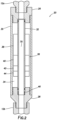
- FIG. 12 is a representative cross-sectional view of a lower connector configuration that may be used with the FIG. 13 acoustic telemetry tool.
- FIG. 13 is a representative cross-sectional view of an intermediate connector section of the FIG. 13 acoustic telemetry tool.
- FIG. 14 is a representative cross-sectional view of another example of the acoustic telemetry tool.
- FIG. 1 Representatively illustrated in FIG. 1 is an acoustic telemetry system 10 for use with a well, and an associated method, which can embody principles of this disclosure.
- system 10 and method are merely one example of an application of the principles of this disclosure in practice, and a wide variety of other examples are possible. Therefore, the scope of this disclosure is not limited at all to the details of the system 10 and method described herein and/or depicted in the drawings.
- a tubular string 12 is deployed into a generally vertical wellbore 14 .
- the wellbore 14 could be horizontal or otherwise inclined from vertical.
- the wellbore 14 is lined with casing 16 and cement 18 , but in other examples the principles of this disclosure can be practiced in open hole or uncased wellbores.
- the tubular string 12 may comprise any type of tubular string configured for use in a subterranean well.
- the tubular string 12 could be a drill string, a work string, a drill stem test string, a stimulation string, a treatment string, a production string or an injection string.
- the tubular string 12 could comprise jointed or continuous tubing. The scope of this disclosure is not limited to use of any particular type of tubular string.
- the tubular string 12 could instead comprise a continuous or jointed rod string (such as, of the type used in artificial lift operations) and, thus, may not be tubular in form. Any media capable of conducting acoustic signals in a well may be used in place of, or in addition to, the tubular string 12 .
- an acoustic telemetry tool 20 is connected in the tubular string 12 .
- An upper section 12 a of the tubular string 12 is connected uphole of the acoustic telemetry tool 20
- a lower section 12 b of the tubular string is connected downhole of the acoustic telemetry tool.
- the acoustic telemetry tool 20 is capable of transmitting acoustic signals 22 to the upper section 12 a of the tubular string 12 , and is capable of receiving acoustic signals 24 from the upper section.
- the acoustic telemetry tool 20 is capable of transmitting acoustic signals 22 to the lower section 12 b of the tubular string 12 , and is capable of receiving acoustic signals 24 from the lower section.
- the acoustic telemetry tool 20 could be configured to receive acoustic signals 24 from one of the upper and lower sections 12 a,b , and to transmit acoustic signals 22 to the other one of the upper and lower sections, thus performing a relaying function.
- the acoustic telemetry tool 20 could be configured to only transmit acoustic signals 22 , such as, to transmit sensor readings to surface or another remote location.
- the acoustic telemetry tool 20 could be configured to only receive acoustic signals 24 , such as, to receive instructions or commands, sensor readings or other data for storage, processing or communication via another telemetry system. Accordingly, the scope of this disclosure is not limited to any particular direction of communication between the acoustic telemetry tool 20 and the remainder of the tubular string 12 .
- the acoustic telemetry tool 20 in the FIG. 1 example is configured to withstand relatively large mechanical loads (tension, compression, bending, torque, etc.).
- the acoustic telemetry tool 20 can transmit relatively large mechanical loads between the upper and lower sections 12 a,b of the tubular string 12 . This capability can be particularly useful when the tubular string 12 is, for example, a drill string, a liner running string, subjected to high pressure and high temperature conditions, etc.
- FIGS. 2 - 14 Representatively illustrated in FIGS. 2 - 14 are examples of the acoustic telemetry tool 20 . These acoustic telemetry tool 20 examples can be used in the system 10 and method of FIG. 1 , or the acoustic telemetry tool examples can be used in other systems and methods.
- the acoustic telemetry tool 20 in these examples includes string connectors at respective opposite ends of the acoustic telemetry tool, a tubular outer housing extending longitudinally between the connectors, an inner mandrel extending longitudinally between the connectors, an annular chamber formed radially between the outer housing and the inner mandrel, and an acoustic telemetry assembly positioned in the annular chamber.
- the outer housing is configured to transmit mechanical loads between the connectors, but the inner mandrel is configured to not transmit mechanical loads between the connectors.
- the outer housing and the inner mandrel are both configured to transmit mechanical loads between the connectors.
- the acoustic telemetry tool 20 includes tubular or rod string connectors 26 , 28 at respective opposite ends of the acoustic telemetry tool, a tubular outer housing 30 extending longitudinally between the connectors, a tubular inner mandrel 32 extending longitudinally between the connectors, an annular chamber 34 formed radially between the outer housing and the inner mandrel, and an acoustic telemetry assembly 36 positioned in the annular chamber.
- a flow passage 70 of the tubular string 12 extends longitudinally through the acoustic telemetry tool 20 .
- the inner mandrel 32 is depicted in the drawings as being in tubular form, with the flow passage 70 extending longitudinally through the inner mandrel, in other examples the inner mandrel may not be tubular and the flow passage may not extend through the inner mandrel.
- the inner mandrel 32 could be solid, or the flow passage 70 could be otherwise located (or not provided at all, such as, if the acoustic telemetry tool is connected in a rod string).
- the scope of this disclosure is not limited to any particular shape or configuration of any of the components of the acoustic telemetry tool 20 .
- the outer housing 30 serves not only to contain the acoustic telemetry assembly 36 , but also to transmit the mechanical loads between the upper and lower string connectors 26 , 28 . Since the upper string connector 26 is secured (e.g., using threads) with the upper section 12 a of the tubular string 12 , and the lower string connector 28 is secured (e.g., using threads) with the lower section 12 b of the tubular string, the outer housing 30 also transmits the mechanical loads between the upper and lower sections 12 a,b . The outer housing 30 can also transmit acoustic signals 22 , 24 (see FIG. 1 ) between the string connectors 26 , 28 .
- the acoustic telemetry assembly 36 is rigidly secured to an exterior of the inner mandrel 32 .
- the acoustic telemetry assembly 36 can be made up of multiple modules, each of which is separately clamped or otherwise secured to the inner mandrel 32 (see FIG. 6 ), or the entire acoustic telemetry assembly could be secured to the inner mandrel as a unit.
- components of the acoustic telemetry assembly 36 could be received in recesses formed on or secured to the inner mandrel 32 .
- components of the acoustic telemetry assembly 36 could be secured to one or both of the connectors 26 , 28 and/or the outer housing 30 .
- the scope of this disclosure is not limited to any particular manner in which the acoustic telemetry assembly 36 is mounted to, secured with or connected to the inner mandrel 32 .
- the mounting, securing or connecting method is designed for optimal communication of acoustic signals 22 and/or 24 between the inner mandrel 32 and at least certain components of the acoustic telemetry assembly 36 (such as, acoustic transmitter and/or receiver components).
- the acoustic telemetry assembly 36 includes batteries 38 , electronic circuitry 40 , an acoustic receiver or sensor 42 , and an acoustic transmitter 44 .
- batteries 38 electronic circuitry 40
- an acoustic receiver or sensor 42 electronic circuitry 40
- an acoustic transmitter 44 acoustic transmitter 44
- more, fewer or a different combination of components may be used.
- the scope of this disclosure is not limited to any particular components or combination of components in the acoustic telemetry assembly 36 .
- the batteries 38 provide electrical power for the electronic circuitry 40 and the acoustic telemetry devices (the acoustic sensor 42 and transmitter 44 ).
- the acoustic sensor 42 is capable of detecting acoustic signals 24 transmitted in the inner mandrel 32
- the acoustic transmitter 44 is capable of transmitting acoustic signals 22 to the inner mandrel.
- the electronic circuitry 40 controls operation of the acoustic telemetry devices 42 , 44 and provides storage and processing of received acoustic signals 24 . Instructions for operation of the acoustic telemetry assembly 36 can be stored in memory of the electronic circuitry 40 .
- the inner mandrel 32 is secured with the lower string connector 28 using threads 46 .
- other securing methods such as, welding, integrally forming, etc.
- the securing method is designed to efficiently transmit acoustic signals 22 , 24 between the inner mandrel 32 and the lower string connector 28 , so that the acoustic telemetry devices 42 , 44 are in acoustic communication with the upper and lower sections 12 a,b of the tubular string 12 via the inner mandrel 32 , the lower string connector 28 , the outer housing 30 and the upper string connector 26 .
- an upper end of the inner mandrel 32 is sealingly and slidingly received in the upper string connector 26 .
- the upper end of the inner mandrel 32 is longitudinally displaceable relative to the string connector 26 .
- the upper end of the inner mandrel 32 could be secured to the string connector 26 (e.g., using threads, etc.), or a biasing device could be installed between the upper end of the inner mandrel and the string connector in order to pre-load the inner mandrel in compression. In this manner, acoustic signals 22 , 24 could be transmitted between the upper end of the inner mandrel 32 and the upper string connector 26 .
- FIG. 3 a cross-sectional view of another example of the acoustic telemetry tool 20 is representatively illustrated.
- mechanical loads are transmitted between the upper and lower string connectors 26 , 28 by the inner mandrel 32 and by the outer housing 30 .
- the upper end of the inner mandrel 32 is secured with the upper string connector 26 using threads 46 , similar to the manner in which the lower end of the inner mandrel is secured with the lower string connector 28 .
- Other methods of securely connecting the ends of the inner mandrel 32 with the string connectors 26 , 28 may be used in other examples.
- an end of the inner mandrel 32 could be integrally formed with one of the string connectors 26 , 28 .
- the upper and lower ends of the outer housing 30 are secured with the respective upper and lower string connectors 26 , 28 using threads 48 .
- Other methods of securely connecting the ends of the outer housing 30 with the string connectors 26 , 28 may be used in other examples.
- the outer housing 30 and the inner mandrel 32 may be designed to share the mechanical loads evenly, or in other proportions.
- the outer housing 30 may have a larger cross-sectional area and moment of inertia than the inner mandrel 32 , and so the outer housing may be able to bear more of the mechanical loading than the inner mandrel.
- both of the outer housing 30 and the inner mandrel 32 can communicate acoustic signals 22 , 24 between the string connectors 26 , 28 .
- both of the outer housing 30 and the inner mandrel 32 can communicate acoustic signals 22 , 24 between the upper and lower tubular string sections 12 a,b.
- FIG. 4 A a cross-sectional view of another example of the acoustic telemetry tool 20 is representatively illustrated.
- mechanical loads are transmitted between the upper and lower string connectors 26 , 28 by multiple outer housings 30 a,b .
- a tubular intermediate connector 50 is secured between the outer housings 30 a,b with threads 48 .
- mechanical loads and acoustic signals 22 , 24 can be communicated between the string connectors 26 , 28 via the connected outer housings 30 a,b and the intermediate connector 50 .
- a acoustic telemetry tool 20 also includes multiple inner mandrels 32 a,b .
- An upper end of the upper inner mandrel 32 a is secured with the string connector 26 by threads 46 , and a lower end is slidingly and sealingly received in the intermediate connector 50 .
- a lower end of the lower inner mandrel 32 b is secured with the string connector 28 by threads 46 , and an upper end is slidingly and sealingly received in the intermediate connector 50 .
- the inner mandrels 32 a,b are not configured to transmit mechanical loads between the string connectors 26 , 28 , but acoustic signals 22 , 24 can be communicated between each of the inner mandrels 32 a,b and the respective string connector 26 , 28 .
- the threads 46 may be replaced by other types of rigid connections capable of transmitting acoustic signals.
- flanged, bolted or welded joints may be used in place of the threads 46 .
- Acoustic telemetry assemblies 36 a,b are contained in respective annular chambers 34 a,b formed radially between the outer housings 30 a,b and the inner mandrels 32 a,b .
- the acoustic telemetry assemblies 36 a,b are the same, but in other examples they could be different (such as, with different components or different types of components, etc.).
- An opening 52 extending longitudinally through the intermediate connector 50 can provide for wired, hydraulic, optical or other forms of communication between the acoustic telemetry assemblies 36 a,b.
- FIG. 4 A there are two sets of outer housing, inner mandrel and acoustic telemetry assembly connected between the string connectors 26 , 28 , in other examples other numbers of sets could be used.
- a separate intermediate connector 50 could be connected between each adjacent pair of the sets.
- FIG. 4 B an optional configuration of the acoustic telemetry tool 20 is representatively illustrated.
- the FIG. 4 B example is similar in most respects to the FIG. 4 A example, but differs in that the intermediate connector 50 is not used and a single outer housing 30 is used in place of the multiple outer housings 30 a,b.
- the upper and lower inner mandrels 32 a,b are slidingly and sealingly engaged with each other. Both of the acoustic telemetry assemblies 36 a,b are contained in the outer housing 30 .
- FIG. 5 a cross-sectional view of another example of the acoustic telemetry tool 20 is representatively illustrated.
- the FIG. 5 example is similar in many respects to the FIG. 2 example.
- the outer housing 30 is secured with each of the string connectors 26 , 28 by threads 48 .
- mechanical loads and acoustic signals 22 , 24 can be transmitted between the string connectors 26 , 28 via the outer housing 30 .
- Other methods of securely connecting the outer housing 30 to the string connectors 26 , 28 may be used in other examples.
- a lower end of the inner mandrel 32 is secured with the string connector 28 by threads 46 .
- An upper end of the inner mandrel 32 is slidingly and sealingly received in the string connector 26 .
- the inner mandrel 32 is not configured to transmit mechanical loads or acoustic signals 22 , 24 between the string connectors 26 , 28 , but the threaded connection at the lower end of the inner mandrel can permit communication of acoustic signals 22 , 24 between the inner mandrel and the string connector 28 .
- annular recess 54 is formed externally on the inner mandrel 32 .
- the annular recess 54 is disposed longitudinally between the string connector 26 and an external shoulder 56 on the inner mandrel 32 .
- a biasing device may be positioned in the annular recess 54 , in order to apply a compressive force or pre-load in the inner mandrel 32 . If the biasing device has a sufficient stiffness, it may be possible to communicate acoustic signals 22 , 24 between the upper end of the inner mandrel 32 and the string connector 26 .
- FIG. 6 a perspective view of an example of the acoustic telemetry assembly 36 is representatively illustrated.
- two sets of the batteries 38 are used.
- the batteries 38 , electronic circuitry 40 , acoustic sensor 42 and acoustic transmitter 44 are each disposed in a respective module 58 a - e .
- the separate modules 58 a - e are clamped onto the exterior of the inner mandrel 32 .
- FIG. 7 a cross-sectional view of a section of the FIG. 5 acoustic telemetry module 20 is representatively illustrated.
- a biasing device 60 can be seen disposed in the annular recess 54 between the string connector 26 and the shoulder 56 .
- the biasing device 60 can apply a compressive force or pre-load to the inner mandrel 32 , as discussed above.
- a tubular spacer 62 is positioned between the biasing device 60 and the string connector 26 .
- a length of the spacer 62 can be changed to accommodate different biasing device 60 lengths, or to achieve different amounts of compressive pre-load in the inner mandrel 32 .
- the biasing device 60 may comprise any type of compression spring (such as, coiled, wave and disc (Belleville washers) may be used), resilient material, or a gas or liquid spring.
- the biasing device 60 and any spacer 62 can be designed to permit acoustic communication between the string connector 26 and the upper end of the inner mandrel 32 , while mechanical loads (other than the compressive force exerted by the biasing device 60 ) cannot be transmitted between the string connector and the upper end of the inner mandrel.
- FIGS. 8 & 9 perspective views of a section of the acoustic telemetry tool 20 are representatively illustrated.
- the biasing device 60 is in the form of a wave spring positioned between the spacer 62 and the shoulder 56 (see FIG. 8 ) on the inner mandrel 32 .
- the biasing device 60 is in the form of a coiled spring and the spacer 62 is not used.
- FIG. 10 a cross-sectional view of another example of the acoustic telemetry tool 20 is representatively illustrated.
- the FIG. 10 example is similar in many respects to the FIG. 3 example.
- both the outer housing 30 and the inner mandrel 32 are capable of transmitting mechanical loads and acoustic signals 22 , 24 between the string connectors 26 , 28 .
- torque-resisting dogs 64 are installed through the string connectors 26 , 28 and into slots formed near the upper and lower ends of the inner mandrel 32 .
- Torque-resisting dogs 68 are installed through radial openings at opposite ends of the outer housing 30 and into slots formed on the respective string connectors 26 , 28 . The dogs 64 , 68 prevent relative rotation between each of the outer housing 30 , the inner mandrel 32 and the string connectors 26 , 28 .
- FIG. 11 a cross-sectional view of another example of the acoustic telemetry tool 20 is representatively illustrated.
- the FIG. 11 example is similar in many respects to the FIG. 4 example.
- the acoustic telemetry tool 20 includes two sets of outer housings 30 a,b , inner mandrels 32 a,b and acoustic telemetry assemblies 36 a,b .
- An intermediate connector 50 is securely connected between the two sets of outer housings 30 a,b by respective threads 48 .
- the outer housings 30 a,b and inner mandrels 32 a,b are securely connected to the respective string connectors 26 , 28 by corresponding threads 48 , 46 .
- the inner mandrels 32 a,b are slidingly and sealingly received in respective opposite ends of the intermediate connector 50 .
- mechanical loads and acoustic signals 22 , 24 can be transmitted between the string connectors 26 , 28 via the outer housings 30 a,b and the intermediate connector 50 .
- Acoustic signals 22 , 24 can also be transmitted between the string connector 26 and the upper end of the inner mandrel 32 a , and between the string connector 28 and the lower end of the inner mandrel 32 b.
- the inner mandrels 32 a,b do not transmit mechanical loads between the string connectors 26 , 28 .
- biasing devices such as, the biasing devices 60 described above
- acoustic signals 22 , 24 could be transmitted between the string connectors 26 , 28 and the respective inner mandrels 32 a,b via the biasing devices.
- FIG. 12 a cross-sectional view of a section of the FIG. 11 acoustic telemetry tool 20 is representatively illustrated.
- a lower end of the inner mandrel 32 b is threadedly secured to an upper end of the string connector 28 .
- a lower end of the outer housing 30 b is also threadedly secured to the string connector 28 .
- torque-resisting dogs 68 could be used to prevent relative rotation between the outer housing 30 b and the string connector 28 .
- FIG. 13 a cross-sectional view of another section of the FIG. 11 acoustic telemetry tool 20 is representatively illustrated.
- the outer housings 30 a,b are threadedly secured to respective opposite ends of the intermediate connector 50 .
- the inner mandrels 32 a,b are slidingly and sealingly received in the respective opposite ends of the intermediate connector 50 .
- Biasing devices 60 may be installed in the annular recesses 54 to bias the inner mandrels 32 a,b away from the intermediate connector 50 , and to apply a compressive pre-load to the inner mandrels.
- FIG. 14 a cross-sectional view of a variation of the FIG. 11 acoustic telemetry tool 20 example is representatively illustrated.
- the intermediate connector 50 is not used.
- a single outer housing 30 extends between the string connectors 26 , 28 .
- Both of the acoustic telemetry assemblies 36 a,b are contained in the outer housing 30 .
- An upper end of the inner mandrel 32 b is slidingly and sealingly received in a lower end of the inner mandrel 32 a .
- the inner mandrels 32 a,b may be biased away from each other by installing a biasing device 60 in an annular recess 54 formed on the inner mandrel 32 b .
- the biasing device 60 exerts a compressive force that is applied to each of the inner mandrels 32 a,b . In this manner, acoustic signals 22 , 24 can be transmitted between the acoustic telemetry assemblies 36 a,b.
- an acoustic telemetry tool 20 is configured to transmit relatively high mechanical loads through the tubular string 12 , and to communicate acoustic signals 22 , 24 in the tubular string.
- the acoustic telemetry tool 20 can include: first and second string connectors 26 , 28 at respective opposite ends of the acoustic telemetry tool 20 ; a tubular outer housing 30 extending longitudinally between the first and second connectors 26 , 28 ; an inner mandrel 32 extending longitudinally between the first and second connectors 26 , 28 , an annular chamber 34 being formed radially between the outer housing 30 and the inner mandrel 32 ; and an acoustic telemetry assembly 36 positioned in the annular chamber 34 .
- the outer housing 30 is configured to transmit mechanical loads between the first and second connectors 26 , 28
- the inner mandrel 32 is configured to not transmit the mechanical loads between the first and second connectors 26 , 28 .
- the acoustic telemetry assembly 36 may be configured for communication of acoustic signals 22 , 24 between the acoustic telemetry assembly 36 and the outer housing 30 .
- the acoustic telemetry assembly 36 may be rigidly secured to the inner mandrel 32 .
- the acoustic telemetry assembly 36 may be clamped to the inner mandrel 32 .
- the acoustic telemetry assembly 36 may include at least one battery 38 , electronic circuitry 40 and an acoustic telemetry device selected from the group consisting of an acoustic transmitter 44 and an acoustic sensor 42 .
- the inner mandrel 32 may be threadedly secured with the second connector 28 , and the inner mandrel 32 may be longitudinally displaceable relative to the first connector 26 .
- the inner mandrel 32 may be slidingly and sealingly received in the first connector 26 .
- a biasing device 60 may apply a compressive force to the inner mandrel 32 .
- acoustic telemetry tool 20 example comprising: first and second string connectors 26 , 28 at respective opposite ends of the acoustic telemetry tool 20 ; a tubular outer housing 30 extending longitudinally between the first and second connectors 26 , 28 ; an inner mandrel 32 extending longitudinally between the first and second connectors 26 , 28 , an annular chamber 34 being formed radially between the outer housing 30 and the inner mandrel 32 ; and an acoustic telemetry assembly 36 positioned in the annular chamber 34 .
- the inner mandrel 32 and the outer housing 30 are configured to transmit mechanical loads between the first and second connectors 26 , 28 .
- the acoustic telemetry assembly 36 may be configured for communication of acoustic signals 22 , 24 between the inner mandrel 32 and the first and second connectors 26 , 28 .
- the inner mandrel 32 may be threadedly secured with the second connector 28 , and integrally formed with the first connector 26 .
- the inner mandrel 32 may be threadedly secured with the second connector 28 , and the inner mandrel 32 may be threadedly secured with the first connector 26 .
- a biasing device 60 may apply a compressive force to the inner mandrel 32 .
- an acoustic telemetry tool 20 example comprising: first and second string connectors 26 , 28 at respective opposite ends of the acoustic telemetry tool 20 ; a first outer housing 30 ; first and second inner mandrels 32 a,b extending longitudinally between the first and second connectors 26 , 28 ; a first annular chamber 34 formed radially between the first outer housing 30 and the first inner mandrel 32 a ; and a first acoustic telemetry assembly 36 a positioned in the first annular chamber 34 .
- the first outer housing 30 may be configured to transmit mechanical loads between the first and second connectors 26 , 28 .
- the first inner mandrel 32 a may not be configured to transmit the mechanical loads.
- the first acoustic telemetry assembly 36 a may be rigidly secured to the first inner mandrel 32 a .
- a biasing device 60 may apply a compressive force to the first inner mandrel 32 a.
- the acoustic telemetry tool 20 may include an intermediate connector 50 .
- the first inner mandrel 32 a may extend longitudinally between the first connector 26 and the intermediate connector 50
- the second inner mandrel 32 b may extend longitudinally between the second connector 28 and the intermediate connector 50 .
- the acoustic telemetry tool 20 may include a second outer housing 30 b .
- the first outer housing 30 a may extend longitudinally between the first connector 26 and the intermediate connector 50
- the second outer housing 30 b may extend longitudinally between the second connector 28 and the intermediate connector 50 .
- the acoustic telemetry tool 20 may include a second annular chamber 34 b formed radially between the second outer housing 30 b and the second inner mandrel 32 b , and a second acoustic telemetry assembly 36 b positioned in the second annular chamber 34 b .
- Each of the acoustic telemetry assemblies 36 a,b could include at least one battery 38 , electronic circuitry 40 and an acoustic telemetry device selected from the group consisting of an acoustic transmitter 44 and an acoustic sensor 42 .
- one of the acoustic telemetry assemblies 36 a,b could include the battery 38 and electronic circuitry 40
- the other acoustic telemetry assembly could include the acoustic transmitter 44 and/or the acoustic sensor 42 .
- the first inner mandrel 32 a may be threadedly secured with the first connector 26 , and the first inner mandrel 32 a may be slidingly and sealingly received in the intermediate connector 50 .
Landscapes
- Engineering & Computer Science (AREA)
- Physics & Mathematics (AREA)
- Geology (AREA)
- Life Sciences & Earth Sciences (AREA)
- Mining & Mineral Resources (AREA)
- Environmental & Geological Engineering (AREA)
- Fluid Mechanics (AREA)
- General Life Sciences & Earth Sciences (AREA)
- Geochemistry & Mineralogy (AREA)
- Acoustics & Sound (AREA)
- Geophysics (AREA)
- Mechanical Engineering (AREA)
- Remote Sensing (AREA)
- Earth Drilling (AREA)
Abstract
Description
Claims (23)
Priority Applications (6)
| Application Number | Priority Date | Filing Date | Title |
|---|---|---|---|
| US17/728,009 US12084965B2 (en) | 2022-04-25 | 2022-04-25 | Acoustic telemetry tool for high mechanical loading |
| EP23713154.5A EP4515078A1 (en) | 2022-04-25 | 2023-03-08 | Acoustic telemetry tool for high mechanical loading |
| PCT/IB2023/052211 WO2023209452A1 (en) | 2022-04-25 | 2023-03-08 | Acoustic telemetry tool for high mechanical loading |
| AU2023258550A AU2023258550A1 (en) | 2022-04-25 | 2023-03-08 | Acoustic telemetry tool for high mechanical loading |
| CA3249394A CA3249394A1 (en) | 2022-04-25 | 2023-03-08 | Acoustic telemetry tool for high mechanical loading |
| MX2024013149A MX2024013149A (en) | 2022-04-25 | 2024-10-24 | Acoustic telemetry tool for high mechanical loading |
Applications Claiming Priority (1)
| Application Number | Priority Date | Filing Date | Title |
|---|---|---|---|
| US17/728,009 US12084965B2 (en) | 2022-04-25 | 2022-04-25 | Acoustic telemetry tool for high mechanical loading |
Publications (2)
| Publication Number | Publication Date |
|---|---|
| US20230340874A1 US20230340874A1 (en) | 2023-10-26 |
| US12084965B2 true US12084965B2 (en) | 2024-09-10 |
Family
ID=85772048
Family Applications (1)
| Application Number | Title | Priority Date | Filing Date |
|---|---|---|---|
| US17/728,009 Active 2042-12-08 US12084965B2 (en) | 2022-04-25 | 2022-04-25 | Acoustic telemetry tool for high mechanical loading |
Country Status (6)
| Country | Link |
|---|---|
| US (1) | US12084965B2 (en) |
| EP (1) | EP4515078A1 (en) |
| AU (1) | AU2023258550A1 (en) |
| CA (1) | CA3249394A1 (en) |
| MX (1) | MX2024013149A (en) |
| WO (1) | WO2023209452A1 (en) |
Cited By (1)
| Publication number | Priority date | Publication date | Assignee | Title |
|---|---|---|---|---|
| US20250075615A1 (en) * | 2023-09-04 | 2025-03-06 | Schlumberger Technology Corporation | Fluid sealing for downhole acoustic measurement tool |
Citations (4)
| Publication number | Priority date | Publication date | Assignee | Title |
|---|---|---|---|---|
| US4283780A (en) | 1980-01-21 | 1981-08-11 | Sperry Corporation | Resonant acoustic transducer system for a well drilling string |
| EP0919696A2 (en) | 1997-12-01 | 1999-06-02 | Halliburton Energy Services, Inc. | Electromagnetic and acoustic repeater and method for use of same |
| US20190226330A1 (en) | 2016-10-13 | 2019-07-25 | Baker Hughes Oilfield Operations Llc | Method and apparatus for pre-loading a piezoelectric transducer for downhole acoustic communication |
| US10415376B2 (en) * | 2016-08-30 | 2019-09-17 | Exxonmobil Upstream Research Company | Dual transducer communications node for downhole acoustic wireless networks and method employing same |
-
2022
- 2022-04-25 US US17/728,009 patent/US12084965B2/en active Active
-
2023
- 2023-03-08 WO PCT/IB2023/052211 patent/WO2023209452A1/en not_active Ceased
- 2023-03-08 CA CA3249394A patent/CA3249394A1/en active Pending
- 2023-03-08 AU AU2023258550A patent/AU2023258550A1/en active Pending
- 2023-03-08 EP EP23713154.5A patent/EP4515078A1/en active Pending
-
2024
- 2024-10-24 MX MX2024013149A patent/MX2024013149A/en unknown
Patent Citations (6)
| Publication number | Priority date | Publication date | Assignee | Title |
|---|---|---|---|---|
| US4283780A (en) | 1980-01-21 | 1981-08-11 | Sperry Corporation | Resonant acoustic transducer system for a well drilling string |
| EP0919696A2 (en) | 1997-12-01 | 1999-06-02 | Halliburton Energy Services, Inc. | Electromagnetic and acoustic repeater and method for use of same |
| US6144316A (en) * | 1997-12-01 | 2000-11-07 | Halliburton Energy Services, Inc. | Electromagnetic and acoustic repeater and method for use of same |
| US10415376B2 (en) * | 2016-08-30 | 2019-09-17 | Exxonmobil Upstream Research Company | Dual transducer communications node for downhole acoustic wireless networks and method employing same |
| US20190226330A1 (en) | 2016-10-13 | 2019-07-25 | Baker Hughes Oilfield Operations Llc | Method and apparatus for pre-loading a piezoelectric transducer for downhole acoustic communication |
| US10669842B2 (en) * | 2016-10-13 | 2020-06-02 | Baker Hughes, A Ge Company, Llc | Method and apparatus for pre-loading a piezoelectric transducer for downhole acoustic communication |
Non-Patent Citations (5)
| Title |
|---|
| Baker Hughes; "XACT bi-directional acoustic telemetry service", product brochure 81686, dated 2021, 2 pages. |
| Halliburton; "Dynalink Telemetry System", product presentation H07823, dated Jul. 2011, 6 pages. |
| International Search Report with Written Opinion issued Jun. 20, 2023 for PCT Patent Application No. PCT/IB2023/052211, 13 pages. |
| Sandia National Laboratories; "Acoustic Telemetry", Sandia Report SAND2003-2614, dated Aug. 2003, 90 pages. |
| Schlumberger; "Muzic wireless telemetry", product brochure 21-RPEV-861568, dated 2021, 1 page. |
Cited By (2)
| Publication number | Priority date | Publication date | Assignee | Title |
|---|---|---|---|---|
| US20250075615A1 (en) * | 2023-09-04 | 2025-03-06 | Schlumberger Technology Corporation | Fluid sealing for downhole acoustic measurement tool |
| US12305503B2 (en) * | 2023-09-04 | 2025-05-20 | Schlumberger Technology Corporation | Fluid sealing for downhole acoustic measurement tool |
Also Published As
| Publication number | Publication date |
|---|---|
| CA3249394A1 (en) | 2023-11-02 |
| AU2023258550A1 (en) | 2024-11-07 |
| WO2023209452A1 (en) | 2023-11-02 |
| MX2024013149A (en) | 2024-12-06 |
| EP4515078A1 (en) | 2025-03-05 |
| US20230340874A1 (en) | 2023-10-26 |
Similar Documents
| Publication | Publication Date | Title |
|---|---|---|
| US10100586B2 (en) | Downhole electrical connector | |
| US10280735B2 (en) | Downhole sensor tool with a sealed sensor outsert | |
| US9715024B2 (en) | Near-field electromagnetic communications network for downhole telemetry | |
| US10494885B2 (en) | Mud pulse telemetry with continuous circulation drilling | |
| US7458420B2 (en) | Downhole measurement system and method | |
| US7730956B2 (en) | Downhole pressure balanced electrical connections | |
| US20090045974A1 (en) | Short Hop Wireless Telemetry for Completion Systems | |
| US7497254B2 (en) | Pocket for a downhole tool string component | |
| US20060016595A1 (en) | Downhole Measurement System and Method | |
| US8118105B2 (en) | Modular electro-hydraulic controller for well tool | |
| US12084965B2 (en) | Acoustic telemetry tool for high mechanical loading | |
| US10822884B1 (en) | Data transmission system | |
| US11499381B2 (en) | Data transmission system | |
| WO2021025727A1 (en) | Data transmission system | |
| US12352159B2 (en) | Wireless electrical lower completion deployment |
Legal Events
| Date | Code | Title | Description |
|---|---|---|---|
| AS | Assignment |
Owner name: WEATHERFORD TECHNOLOGY HOLDINGS, LLC, TEXAS Free format text: ASSIGNMENT OF ASSIGNORS INTEREST;ASSIGNORS:KIRKPATRICK, CAMERON B.;MARTINEZ, RUBEN E.;EMIG, SETH D.;SIGNING DATES FROM 20220408 TO 20220418;REEL/FRAME:059695/0081 |
|
| FEPP | Fee payment procedure |
Free format text: ENTITY STATUS SET TO UNDISCOUNTED (ORIGINAL EVENT CODE: BIG.); ENTITY STATUS OF PATENT OWNER: LARGE ENTITY |
|
| STPP | Information on status: patent application and granting procedure in general |
Free format text: DOCKETED NEW CASE - READY FOR EXAMINATION |
|
| AS | Assignment |
Owner name: WELLS FARGO BANK, NATIONAL ASSOCIATION, NORTH CAROLINA Free format text: SUPPLEMENT NO. 2 TO CONFIRMATORY GRANT OF SECURITY INTEREST IN UNITED STATES PATENTS;ASSIGNORS:WEATHERFORD TECHNOLOGY HOLDINGS, LLC;WEATHERFORD NETHERLANDS B.V.;WEATHERFORD U.K. LIMITED;REEL/FRAME:062389/0239 Effective date: 20221017 |
|
| STPP | Information on status: patent application and granting procedure in general |
Free format text: NON FINAL ACTION MAILED |
|
| STPP | Information on status: patent application and granting procedure in general |
Free format text: RESPONSE TO NON-FINAL OFFICE ACTION ENTERED AND FORWARDED TO EXAMINER |
|
| STPP | Information on status: patent application and granting procedure in general |
Free format text: NOTICE OF ALLOWANCE MAILED -- APPLICATION RECEIVED IN OFFICE OF PUBLICATIONS |
|
| STPP | Information on status: patent application and granting procedure in general |
Free format text: NOTICE OF ALLOWANCE MAILED -- APPLICATION RECEIVED IN OFFICE OF PUBLICATIONS |
|
| STPP | Information on status: patent application and granting procedure in general |
Free format text: PUBLICATIONS -- ISSUE FEE PAYMENT VERIFIED |
|
| STCF | Information on status: patent grant |
Free format text: PATENTED CASE |