US12075028B2 - Image encoding/decoding method and device, and recording medium storing bitstream - Google Patents
Image encoding/decoding method and device, and recording medium storing bitstream Download PDFInfo
- Publication number
- US12075028B2 US12075028B2 US17/761,908 US202017761908A US12075028B2 US 12075028 B2 US12075028 B2 US 12075028B2 US 202017761908 A US202017761908 A US 202017761908A US 12075028 B2 US12075028 B2 US 12075028B2
- Authority
- US
- United States
- Prior art keywords
- block
- prediction
- current block
- information
- mode
- Prior art date
- Legal status (The legal status is an assumption and is not a legal conclusion. Google has not performed a legal analysis and makes no representation as to the accuracy of the status listed.)
- Active, expires
Links
- 238000000034 method Methods 0.000 title claims abstract description 159
- 238000000638 solvent extraction Methods 0.000 claims abstract description 138
- 241000023320 Luma <angiosperm> Species 0.000 abstract description 52
- OSWPMRLSEDHDFF-UHFFFAOYSA-N methyl salicylate Chemical compound COC(=O)C1=CC=CC=C1O OSWPMRLSEDHDFF-UHFFFAOYSA-N 0.000 abstract description 52
- 239000013598 vector Substances 0.000 description 142
- 230000002457 bidirectional effect Effects 0.000 description 133
- 238000005192 partition Methods 0.000 description 115
- 239000000523 sample Substances 0.000 description 106
- 230000006872 improvement Effects 0.000 description 86
- PXFBZOLANLWPMH-UHFFFAOYSA-N 16-Epiaffinine Natural products C1C(C2=CC=CC=C2N2)=C2C(=O)CC2C(=CC)CN(C)C1C2CO PXFBZOLANLWPMH-UHFFFAOYSA-N 0.000 description 43
- 238000013139 quantization Methods 0.000 description 35
- 230000002123 temporal effect Effects 0.000 description 30
- 239000013074 reference sample Substances 0.000 description 27
- 208000037170 Delayed Emergence from Anesthesia Diseases 0.000 description 26
- 230000006978 adaptation Effects 0.000 description 25
- 230000009466 transformation Effects 0.000 description 20
- 239000011159 matrix material Substances 0.000 description 19
- 239000011449 brick Substances 0.000 description 18
- 238000001914 filtration Methods 0.000 description 17
- 230000003044 adaptive effect Effects 0.000 description 16
- 230000008569 process Effects 0.000 description 16
- 238000013507 mapping Methods 0.000 description 13
- 230000006870 function Effects 0.000 description 11
- 238000010586 diagram Methods 0.000 description 10
- 230000011664 signaling Effects 0.000 description 9
- 239000000470 constituent Substances 0.000 description 7
- 230000005540 biological transmission Effects 0.000 description 4
- 230000008859 change Effects 0.000 description 4
- 239000002131 composite material Substances 0.000 description 4
- 238000012986 modification Methods 0.000 description 4
- 230000004048 modification Effects 0.000 description 4
- 241000723655 Cowpea mosaic virus Species 0.000 description 3
- 230000006835 compression Effects 0.000 description 3
- 238000007906 compression Methods 0.000 description 3
- 230000007423 decrease Effects 0.000 description 3
- 238000009795 derivation Methods 0.000 description 3
- 238000006073 displacement reaction Methods 0.000 description 2
- 230000003287 optical effect Effects 0.000 description 2
- 230000001131 transforming effect Effects 0.000 description 2
- 240000007594 Oryza sativa Species 0.000 description 1
- 235000007164 Oryza sativa Nutrition 0.000 description 1
- 238000006243 chemical reaction Methods 0.000 description 1
- 238000010276 construction Methods 0.000 description 1
- 238000013500 data storage Methods 0.000 description 1
- 230000003247 decreasing effect Effects 0.000 description 1
- 230000000694 effects Effects 0.000 description 1
- 230000008451 emotion Effects 0.000 description 1
- 235000009566 rice Nutrition 0.000 description 1
- 238000012163 sequencing technique Methods 0.000 description 1
Images


Classifications
-
- H—ELECTRICITY
- H04—ELECTRIC COMMUNICATION TECHNIQUE
- H04N—PICTORIAL COMMUNICATION, e.g. TELEVISION
- H04N19/00—Methods or arrangements for coding, decoding, compressing or decompressing digital video signals
- H04N19/50—Methods or arrangements for coding, decoding, compressing or decompressing digital video signals using predictive coding
- H04N19/503—Methods or arrangements for coding, decoding, compressing or decompressing digital video signals using predictive coding involving temporal prediction
- H04N19/51—Motion estimation or motion compensation
- H04N19/577—Motion compensation with bidirectional frame interpolation, i.e. using B-pictures
-
- H—ELECTRICITY
- H04—ELECTRIC COMMUNICATION TECHNIQUE
- H04N—PICTORIAL COMMUNICATION, e.g. TELEVISION
- H04N19/00—Methods or arrangements for coding, decoding, compressing or decompressing digital video signals
- H04N19/10—Methods or arrangements for coding, decoding, compressing or decompressing digital video signals using adaptive coding
- H04N19/102—Methods or arrangements for coding, decoding, compressing or decompressing digital video signals using adaptive coding characterised by the element, parameter or selection affected or controlled by the adaptive coding
- H04N19/103—Selection of coding mode or of prediction mode
- H04N19/105—Selection of the reference unit for prediction within a chosen coding or prediction mode, e.g. adaptive choice of position and number of pixels used for prediction
-
- H—ELECTRICITY
- H04—ELECTRIC COMMUNICATION TECHNIQUE
- H04N—PICTORIAL COMMUNICATION, e.g. TELEVISION
- H04N19/00—Methods or arrangements for coding, decoding, compressing or decompressing digital video signals
- H04N19/10—Methods or arrangements for coding, decoding, compressing or decompressing digital video signals using adaptive coding
- H04N19/102—Methods or arrangements for coding, decoding, compressing or decompressing digital video signals using adaptive coding characterised by the element, parameter or selection affected or controlled by the adaptive coding
- H04N19/103—Selection of coding mode or of prediction mode
- H04N19/109—Selection of coding mode or of prediction mode among a plurality of temporal predictive coding modes
-
- H—ELECTRICITY
- H04—ELECTRIC COMMUNICATION TECHNIQUE
- H04N—PICTORIAL COMMUNICATION, e.g. TELEVISION
- H04N19/00—Methods or arrangements for coding, decoding, compressing or decompressing digital video signals
- H04N19/10—Methods or arrangements for coding, decoding, compressing or decompressing digital video signals using adaptive coding
- H04N19/102—Methods or arrangements for coding, decoding, compressing or decompressing digital video signals using adaptive coding characterised by the element, parameter or selection affected or controlled by the adaptive coding
- H04N19/119—Adaptive subdivision aspects, e.g. subdivision of a picture into rectangular or non-rectangular coding blocks
-
- H—ELECTRICITY
- H04—ELECTRIC COMMUNICATION TECHNIQUE
- H04N—PICTORIAL COMMUNICATION, e.g. TELEVISION
- H04N19/00—Methods or arrangements for coding, decoding, compressing or decompressing digital video signals
- H04N19/10—Methods or arrangements for coding, decoding, compressing or decompressing digital video signals using adaptive coding
- H04N19/102—Methods or arrangements for coding, decoding, compressing or decompressing digital video signals using adaptive coding characterised by the element, parameter or selection affected or controlled by the adaptive coding
- H04N19/124—Quantisation
-
- H—ELECTRICITY
- H04—ELECTRIC COMMUNICATION TECHNIQUE
- H04N—PICTORIAL COMMUNICATION, e.g. TELEVISION
- H04N19/00—Methods or arrangements for coding, decoding, compressing or decompressing digital video signals
- H04N19/10—Methods or arrangements for coding, decoding, compressing or decompressing digital video signals using adaptive coding
- H04N19/102—Methods or arrangements for coding, decoding, compressing or decompressing digital video signals using adaptive coding characterised by the element, parameter or selection affected or controlled by the adaptive coding
- H04N19/132—Sampling, masking or truncation of coding units, e.g. adaptive resampling, frame skipping, frame interpolation or high-frequency transform coefficient masking
-
- H—ELECTRICITY
- H04—ELECTRIC COMMUNICATION TECHNIQUE
- H04N—PICTORIAL COMMUNICATION, e.g. TELEVISION
- H04N19/00—Methods or arrangements for coding, decoding, compressing or decompressing digital video signals
- H04N19/10—Methods or arrangements for coding, decoding, compressing or decompressing digital video signals using adaptive coding
- H04N19/134—Methods or arrangements for coding, decoding, compressing or decompressing digital video signals using adaptive coding characterised by the element, parameter or criterion affecting or controlling the adaptive coding
- H04N19/136—Incoming video signal characteristics or properties
-
- H—ELECTRICITY
- H04—ELECTRIC COMMUNICATION TECHNIQUE
- H04N—PICTORIAL COMMUNICATION, e.g. TELEVISION
- H04N19/00—Methods or arrangements for coding, decoding, compressing or decompressing digital video signals
- H04N19/10—Methods or arrangements for coding, decoding, compressing or decompressing digital video signals using adaptive coding
- H04N19/169—Methods or arrangements for coding, decoding, compressing or decompressing digital video signals using adaptive coding characterised by the coding unit, i.e. the structural portion or semantic portion of the video signal being the object or the subject of the adaptive coding
- H04N19/17—Methods or arrangements for coding, decoding, compressing or decompressing digital video signals using adaptive coding characterised by the coding unit, i.e. the structural portion or semantic portion of the video signal being the object or the subject of the adaptive coding the unit being an image region, e.g. an object
- H04N19/176—Methods or arrangements for coding, decoding, compressing or decompressing digital video signals using adaptive coding characterised by the coding unit, i.e. the structural portion or semantic portion of the video signal being the object or the subject of the adaptive coding the unit being an image region, e.g. an object the region being a block, e.g. a macroblock
-
- H—ELECTRICITY
- H04—ELECTRIC COMMUNICATION TECHNIQUE
- H04N—PICTORIAL COMMUNICATION, e.g. TELEVISION
- H04N19/00—Methods or arrangements for coding, decoding, compressing or decompressing digital video signals
- H04N19/10—Methods or arrangements for coding, decoding, compressing or decompressing digital video signals using adaptive coding
- H04N19/169—Methods or arrangements for coding, decoding, compressing or decompressing digital video signals using adaptive coding characterised by the coding unit, i.e. the structural portion or semantic portion of the video signal being the object or the subject of the adaptive coding
- H04N19/186—Methods or arrangements for coding, decoding, compressing or decompressing digital video signals using adaptive coding characterised by the coding unit, i.e. the structural portion or semantic portion of the video signal being the object or the subject of the adaptive coding the unit being a colour or a chrominance component
-
- H—ELECTRICITY
- H04—ELECTRIC COMMUNICATION TECHNIQUE
- H04N—PICTORIAL COMMUNICATION, e.g. TELEVISION
- H04N19/00—Methods or arrangements for coding, decoding, compressing or decompressing digital video signals
- H04N19/50—Methods or arrangements for coding, decoding, compressing or decompressing digital video signals using predictive coding
- H04N19/503—Methods or arrangements for coding, decoding, compressing or decompressing digital video signals using predictive coding involving temporal prediction
- H04N19/51—Motion estimation or motion compensation
-
- H—ELECTRICITY
- H04—ELECTRIC COMMUNICATION TECHNIQUE
- H04N—PICTORIAL COMMUNICATION, e.g. TELEVISION
- H04N19/00—Methods or arrangements for coding, decoding, compressing or decompressing digital video signals
- H04N19/50—Methods or arrangements for coding, decoding, compressing or decompressing digital video signals using predictive coding
- H04N19/593—Methods or arrangements for coding, decoding, compressing or decompressing digital video signals using predictive coding involving spatial prediction techniques
-
- H—ELECTRICITY
- H04—ELECTRIC COMMUNICATION TECHNIQUE
- H04N—PICTORIAL COMMUNICATION, e.g. TELEVISION
- H04N19/00—Methods or arrangements for coding, decoding, compressing or decompressing digital video signals
- H04N19/60—Methods or arrangements for coding, decoding, compressing or decompressing digital video signals using transform coding
- H04N19/61—Methods or arrangements for coding, decoding, compressing or decompressing digital video signals using transform coding in combination with predictive coding
-
- H—ELECTRICITY
- H04—ELECTRIC COMMUNICATION TECHNIQUE
- H04N—PICTORIAL COMMUNICATION, e.g. TELEVISION
- H04N19/00—Methods or arrangements for coding, decoding, compressing or decompressing digital video signals
- H04N19/70—Methods or arrangements for coding, decoding, compressing or decompressing digital video signals characterised by syntax aspects related to video coding, e.g. related to compression standards
-
- H—ELECTRICITY
- H04—ELECTRIC COMMUNICATION TECHNIQUE
- H04N—PICTORIAL COMMUNICATION, e.g. TELEVISION
- H04N19/00—Methods or arrangements for coding, decoding, compressing or decompressing digital video signals
- H04N19/80—Details of filtering operations specially adapted for video compression, e.g. for pixel interpolation
- H04N19/82—Details of filtering operations specially adapted for video compression, e.g. for pixel interpolation involving filtering within a prediction loop
-
- H—ELECTRICITY
- H04—ELECTRIC COMMUNICATION TECHNIQUE
- H04N—PICTORIAL COMMUNICATION, e.g. TELEVISION
- H04N19/00—Methods or arrangements for coding, decoding, compressing or decompressing digital video signals
- H04N19/90—Methods or arrangements for coding, decoding, compressing or decompressing digital video signals using coding techniques not provided for in groups H04N19/10-H04N19/85, e.g. fractals
- H04N19/91—Entropy coding, e.g. variable length coding [VLC] or arithmetic coding
Definitions
- the present invention relates to a method and apparatus for encoding/decoding an image and apparatus, and a recording medium for storing a bitstream.
- HD high definition
- UHD ultra-high definition
- video compression techniques such as an inter prediction technique of predicting the values of pixels within a current picture from the values of pixels within a preceding picture or a subsequent picture, an intra prediction technique of predicting the values of pixels within a region of a current picture from the values of pixels within another region of the current picture, a transform and quantization technique of compressing the energy of a residual signal, and an entropy coding technique of allocating frequently occurring pixel values with shorter codes and less occurring pixel values with longer codes.
- An object of the present invention is to provide an image encoding/decoding method and apparatus with improved compression efficiency.
- Another object of the present invention is to provide an image encoding/decoding method and apparatus by bi-directional inter prediction.
- Another object of the present invention is to provide an image encoding/decoding method and apparatus by using geometric inter prediction.
- Another object of the present invention is to provide a recording medium for storing a bitstream generated by an image encoding/decoding method or apparatus according to the present invention.
- the method of decoding an image comprises, generating a first prediction block of a current block, generating a second prediction block of the current block and generating a final prediction sample of the current block using a sample unit weighted sum of the first prediction block and the second prediction block, wherein a weight used for the sample unit weighted sum is determined based on a location of a current luma sample and a geometric prediction mode (GPM) boundary line for partitioning the current block.
- GPM geometric prediction mode
- the method of decoding an image further comprises, acquiring a GPM partitioning index of the current block and specifying the GPM boundary line based on the GPM partitioning index.
- the GPM partitioning index indicates at least one of a distance from a center of the current block to the GPM boundary line or an angle of the GPM boundary line.
- the GPM boundary line is specified based on at least one of the distance from the center of the current block to the GPM boundary line or the angle of the GPM boundary line.
- a weight applied to the current luma sample is determined based on a distance between a current sample and the GPM boundary line.
- a weight applied to a current chroma sample is determined using a weight of a luma sample corresponding to the current chroma sample.
- a weight applied to the current luma sample is determined to be one of ⁇ 7 ⁇ 8, 6/8, 4/8, 2/8, 1 ⁇ 8 ⁇ .
- the method of decoding an image further comprises, deriving a merge candidate list of the current block and deriving a GPM candidate list of the current block using the merge candidate list.
- the image decoding method of claim 8 wherein at least one of GPM candidate 0, 2 or 4 of the GPM candidate list is derived using L0 motion information of a merge candidate corresponding to the GPM candidate.
- GPM candidate 1, 3 or 5 of the GPM candidate list is derived using L1 motion information of a merge candidate corresponding to the GPM candidate.
- the method of decoding an image further comprises, acquiring a first GPM index and a second GPM index, acquiring first motion information based on the first GPM index and the GPM candidate list and acquiring second motion information based on the second GPM index and the GPM candidate list, wherein the first prediction block is generated based on the first motion information and the second prediction block is generated based on the second motion information.
- the method of decoding an image comprises, generating a first prediction block of a current block, generating a second prediction block of the current block, generating a final prediction sample of the current block using a sample unit weighted sum of the first prediction block and the second prediction block and encoding weight related information used for the sample unit weighted sum, wherein the weight related information is determined based on a location of a current luma sample and a geometric prediction mode (GPM) boundary line for partitioning the current block.
- GPS geometric prediction mode
- the weight related information indicates at least one of a distance from a center of the current block to the GPM boundary line or an angle of the GPM boundary line.
- a computer-readable recording medium for storing a bitstream received by an image decoding apparatus and used to reconstruct a current block included in a current picture, the bitstream being generated by an image encoding method according to the present disclosure, the image encoding method comprising, generating a first prediction block of a current block, generating a second prediction block of the current block, generating a final prediction sample of the current block using a sample unit weighted sum of the first prediction block and the second prediction block and encoding weight related information used for the sample unit weighted sum, wherein the weight related information is determined based on a location of a current luma sample and a geometric prediction mode (GPM) boundary line for partitioning the current block.
- GPS geometric prediction mode
- the present invention it is possible to provide an image encoding/decoding method and apparatus, a recording medium storing a bitstream generated by the image encoding method/apparatus, with improved compression efficiency.
- an image encoding/decoding method and apparatus a recording medium storing a bitstream generated by the image encoding method/apparatus by bi-directional inter prediction.
- an image encoding/decoding method and apparatus a recording medium storing a bitstream generated by the image encoding method/apparatus by geometric inter prediction.
- FIG. 1 is a block diagram showing a configuration of an encoding apparatus according to an embodiment to which the present invention is applied.
- FIG. 2 is a block diagram showing a configuration of a decoding apparatus according to an embodiment and to which the present invention is applied.
- FIG. 3 is a view schematically showing a partition structure of an image when encoding and decoding the image.
- FIG. 4 is a view showing an intra-prediction process.
- FIG. 5 is a diagram illustrating an embodiment of an inter-picture prediction process.
- FIG. 6 is a diagram illustrating a transform and quantization process.
- FIG. 7 is a diagram illustrating reference samples capable of being used for intra prediction.
- FIG. 8 is a view illustrating an image decoding method according to an embodiment of the present disclosure.
- FIG. 9 is a view illustrating an image encoding method according to an embodiment of the present disclosure.
- FIG. 10 is a view illustrating an image decoding method according to another embodiment of the present disclosure.
- FIG. 11 is a view illustrating an image encoding method according to another embodiment of the present disclosure.
- FIG. 12 is a view illustrating a method of a history-based motion vector predictor (HMVP) candidate list.
- HMVP history-based motion vector predictor
- FIG. 13 is a view illustrating a spatial neighboring block which may be used in several embodiments of the present disclosure.
- FIG. 14 is a view illustrating a temporal neighboring block which may be used in several embodiments of the present disclosure.
- FIG. 15 is a view illustrating a control point motion vector (CPMV).
- CPMV control point motion vector
- FIG. 16 is a view illustrating a method of applying a triangular prediction mode (TPM) according to an embodiment of the present disclosure.
- TPM triangular prediction mode
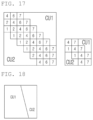
- FIG. 17 is a view illustrating a weight applicable to a TPM according to an embodiment of the present disclosure.
- FIG. 18 is a view illustrating a method of applying a geometric prediction mode (GPM) according to another embodiment of the present disclosure.
- GPS geometric prediction mode
- FIG. 19 is a view illustrating a weight applicable to a GPM according to another embodiment of the present disclosure.
- FIGS. 20 to 24 are views illustrating a weight applicable to a chroma block, to which a GPM according to several embodiments of the present disclosure is applied.
- FIGS. 25 to 27 are views illustrating a method of encoding/decoding motion information of a block, to which a GPM according to several embodiments of the present disclosure is applied.
- FIGS. 28 to 30 are other views illustrating a method of encoding/decoding motion information of a block, to which a GPM according to several embodiments of the present disclosure is applied.
- FIGS. 31 to 35 are views illustrating a method of encoding/decoding intra prediction mode information according to several embodiments of the present disclosure.
- FIGS. 36 and 37 are views illustrating a method of entropy-encoding/decoding GPM information.
- FIG. 38 is a view illustrating an image decoding method according to another embodiment of the present disclosure.
- FIG. 39 is a view illustrating an image encoding method according to another embodiment of the present disclosure.
- FIG. 40 is a view illustrating an image decoding method according to another embodiment of the present disclosure.
- FIG. 41 is a view illustrating an image encoding method according to another embodiment of the present disclosure.
- FIG. 42 is a view illustrating a motion improvement range according to an embodiment of the present disclosure.
- FIGS. 43 and 44 are views illustrating a motion improvement offset according to several embodiments of the present disclosure.
- FIG. 45 is a view illustrating a motion improvement method according to an embodiment of the present disclosure.
- FIG. 46 is another view illustrating a motion improvement method according to an embodiment of the present disclosure.
- FIG. 43 is a view illustrating a motion improvement method.
- FIG. 44 is another view illustrating a motion improvement method.
- first ‘first’, ‘second’, etc. can be used to describe various components, but the components are not to be construed as being limited to the terms. The terms are only used to differentiate one component from other components.
- the ‘first’ component may be named the ‘second’ component without departing from the scope of the present invention, and the ‘second’ component may also be similarly named the ‘first’ component.
- the term ‘and/or’ includes a combination of a plurality of items or any one of a plurality of terms.
- constitutional parts shown in the embodiments of the present invention are independently shown so as to represent characteristic functions different from each other.
- each constitutional part includes each of enumerated constitutional parts for convenience.
- at least two constitutional parts of each constitutional part may be combined to form one constitutional part or one constitutional part may be divided into a plurality of constitutional parts to perform each function.
- the embodiment where each constitutional part is combined and the embodiment where one constitutional part is divided are also included in the scope of the present invention, if not departing from the essence of the present invention.
- constituents may not be indispensable constituents performing essential functions of the present invention but be selective constituents improving only performance thereof.
- the present invention may be implemented by including only the indispensable constitutional parts for implementing the essence of the present invention except the constituents used in improving performance.
- the structure including only the indispensable constituents except the selective constituents used in improving only performance is also included in the scope of the present invention.
- an image may mean a picture configuring a video, or may mean the video itself.
- encoding or decoding or both of an image may mean “encoding or decoding or both of a moving picture”, and may mean “encoding or decoding or both of one image among images of a moving picture.”
- moving picture and “video” may be used as the same meaning and be replaced with each other.
- a target image may be an encoding target image which is a target of encoding and/or a decoding target image which is a target of decoding.
- a target image may be an input image inputted to an encoding apparatus, and an input image inputted to a decoding apparatus.
- a target image may have the same meaning with the current image.
- a target block may be an encoding target block which is a target of encoding and/or a decoding target block which is a target of decoding.
- a target block may be the current block which is a target of current encoding and/or decoding.
- terms “target block” and “current block” may be used as the same meaning and be replaced with each other.
- blocks and units may be used as the same meaning and be replaced with each other. Or a “block” may represent a specific unit.
- region and “segment” may be replaced with each other.
- a specific signal may be a signal representing a specific block.
- an original signal may be a signal representing a target block.
- a prediction signal may be a signal representing a prediction block.
- a residual signal may be a signal representing a residual block.
- each of specific information, data, flag, index, element and attribute, etc. may have a value.
- a value of information, data, flag, index, element and attribute equal to “0” may represent a logical false or the first predefined value. In other words, a value “0”, a false, a logical false and the first predefined value may be replaced with each other.
- a value of information, data, flag, index, element and attribute equal to “1” may represent a logical true or the second predefined value. In other words, a value “1”, a true, a logical true and the second predefined value may be replaced with each other.
- a value of i may be an integer equal to or greater than 0, or equal to or greater than 1. That is, the column, the row, the index, etc. may be counted from 0 or may be counted from 1.
- Encoder means an apparatus performing encoding. That is, means an encoding apparatus.
- Decoder means an apparatus performing decoding. That is, means an decoding apparatus.
- Block is an M ⁇ N array of a sample.
- M and N may mean positive integers, and the block may mean a sample array of a two-dimensional form.
- the block may refer to a unit.
- a current block my mean an encoding target block that becomes a target when encoding, or a decoding target block that becomes a target when decoding.
- the current block may be at least one of an encode block, a prediction block, a residual block, and a transform block.
- Sample is a basic unit constituting a block. It may be expressed as a value from 0 to 2 Bd ⁇ 1 according to a bit depth (B d ).
- the sample may be used as a meaning of a pixel. That is, a sample, a pel, a pixel may have the same meaning with each other.
- Unit may refer to an encoding and decoding unit.
- the unit When encoding and decoding an image, the unit may be a region generated by partitioning a single image.
- the unit may mean a subdivided unit when a single image is partitioned into subdivided units during encoding or decoding. That is, an image may be partitioned into a plurality of units.
- a predetermined process for each unit may be performed.
- a single unit may be partitioned into sub-units that have sizes smaller than the size of the unit.
- the unit may mean a block, a macroblock, a coding tree unit, a code tree block, a coding unit, a coding block), a prediction unit, a prediction block, a residual unit), a residual block, a transform unit, a transform block, etc.
- the unit may include a luma component block, a chroma component block associated with the luma component block, and a syntax element of each color component block.
- the unit may have various sizes and forms, and particularly, the form of the unit may be a two-dimensional geometrical figure such as a square shape, a rectangular shape, a trapezoid shape, a triangular shape, a pentagonal shape, etc.
- unit information may include at least one of a unit type indicating the coding unit, the prediction unit, the transform unit, etc., and a unit size, a unit depth, a sequence of encoding and decoding of a unit, etc.
- Coding Tree Unit is configured with a single coding tree block of a luma component Y, and two coding tree blocks related to chroma components Cb and Cr. In addition, it may mean that including the blocks and a syntax element of each block.
- Each coding tree unit may be partitioned by using at least one of a quad-tree partitioning method, a binary-tree partitioning method and ternary-tree partitioning method to configure a lower unit such as coding unit, prediction unit, transform unit, etc. It may be used as a term for designating a sample block that becomes a process unit when encoding/decoding an image as an input image.
- the quad-tree may mean a quaternary-tree.
- the predetermined range may be defined as at least one of a maximum size and a minimum size of a coding block in which the division is possible using only quad-tree partitioning.
- Information indicating a maximum/minimum size of a coding block in which quad-tree partitioning is allowed may be signaled through a bitstream, and the information may be signaled in at least one unit of a sequence, a picture parameter, a tile group, or a slice (segment).
- the maximum/minimum size of the coding block may be a fixed size predetermined in the coder/decoder.
- the block to be divided may be at least one of a coding block and a transform block.
- information indicating the division of the coded block (for example, split_flag) may be a flag indicating whether or not to perform the quad-tree partitioning.
- Coding Tree Block may be used as a term for designating any one of a Y coding tree block, Cb coding tree block, and Cr coding tree block.
- Neighbor Block may mean a block adjacent to a current block.
- the block adjacent to the current block may mean a block that comes into contact with a boundary of the current block, or a block positioned within a predetermined distance from the current block.
- the neighbor block may mean a block adjacent to a vertex of the current block.
- the block adjacent to the vertex of the current block may mean a block vertically adjacent to a neighbor block that is horizontally adjacent to the current block, or a block horizontally adjacent to a neighbor block that is vertically adjacent to the current block.
- Reconstructed Neighbor block may mean a neighbor block adjacent to a current block and which has been already spatially/temporally encoded or decoded.
- the reconstructed neighbor block may mean a reconstructed neighbor unit.
- a reconstructed spatial neighbor block may be a block within a current picture and which has been already reconstructed through encoding or decoding or both.
- a reconstructed temporal neighbor block is a block at a corresponding position as the current block of the current picture within a reference image, or a neighbor block thereof.
- Unit Depth may mean a partitioned degree of a unit.
- the highest node (Root Node) may correspond to the first unit which is not partitioned. Also, the highest node may have the least depth value. In this case, the highest node may have a depth of level 0.
- a node having a depth of level 1 may represent a unit generated by partitioning once the first unit.
- a node having a depth of level 2 may represent a unit generated by partitioning twice the first unit.
- a node having a depth of level n may represent a unit generated by partitioning n-times the first unit.
- a Leaf Node may be the lowest node and a node which cannot be partitioned further.
- a depth of a Leaf Node may be the maximum level.
- a predefined value of the maximum level may be 3.
- a depth of a root node may be the lowest and a depth of a leaf node may be the deepest.
- a level in which a unit is present may mean a unit depth.
- Bitstream may mean a bitstream including encoding image information.
- Parameter Set corresponds to header information among a configuration within a bitstream. At least one of a video parameter set, a sequence parameter set, a picture parameter set, and an adaptation parameter set may be included in a parameter set.
- a parameter set may include a slice header, a tile group header, and tile header information.
- tile group means a group of tiles and has the same meaning as a slice.
- An adaptation parameter set may mean a parameter set that can be shared by being referred to in different pictures, subpictures, slices, tile groups, tiles, or bricks.
- information in an adaptation parameter set may be used by referring to different adaptation parameter sets for a subpicture, a slice, a tile group, a tile, or a brick inside a picture.
- different adaptation parameter sets may be referred to by using identifiers of different adaptation parameter sets for a subpicture, a slice, a tile group, a tile, or a brick inside a picture.
- different adaptation parameter sets may be referred to by using identifiers of different adaptation parameter sets for a slice, a tile group, a tile, or a brick inside a subpicture.
- adaptation parameter set different adaptation parameter sets may be referred to by using identifiers of different adaptation parameter sets for a tile or a brick inside a slice.
- adaptation parameter set different adaptation parameter sets may be referred to by using identifiers of different adaptation parameter sets for a brick inside a tile.
- Information on an adaptation parameter set identifier may be included in a parameter set or a header of the subpicture, and an adaptation parameter set corresponding to the adaptation parameter set identifier may be used for the subpicture.
- the information on the adaptation parameter set identifier may be included in a parameter set or a header of the tile, and an adaptation parameter set corresponding to the adaptation parameter set identifier may be used for the tile.
- the information on the adaptation parameter set identifier may be included in a header of the brick, and an adaptation parameter set corresponding to the adaptation parameter set identifier may be used for the brick.
- the picture may be partitioned into one or more tile rows and one or more tile columns.
- the subpicture may be partitioned into one or more tile rows and one or more tile columns within a picture.
- the subpicture may be a region having the form of a rectangle/square within a picture and may include one or more CTUs.
- at least one or more tiles/bricks/slices may be included within one subpicture.
- the tile may be a region having the form of a rectangle/square within a picture and may include one or more CTUs. In addition, the tile may be partitioned into one or more bricks.
- the brick may mean one or more CTU rows within a tile.
- the tile may be partitioned into one or more bricks, and each brick may have at least one or more CTU rows.
- a tile that is not partitioned into two or more may mean a brick.
- the slice may include one or more tiles within a picture and may include one or more bricks within a tile.
- Parsing may mean determination of a value of a syntax element by performing entropy decoding, or may mean the entropy decoding itself.
- Symbol may mean at least one of a syntax element, a coding parameter, and a transform coefficient value of an encoding/decoding target unit.
- the symbol may mean an entropy encoding target or an entropy decoding result.
- Prediction Mode may be information indicating a mode encoded/decoded with intra prediction or a mode encoded/decoded with inter prediction.
- Prediction Unit may mean a basic unit when performing prediction such as inter-prediction, intra-prediction, inter-compensation, intra-compensation, and motion compensation.
- a single prediction unit may be partitioned into a plurality of partitions having a smaller size, or may be partitioned into a plurality of lower prediction units.
- a plurality of partitions may be a basic unit in performing prediction or compensation.
- a partition which is generated by dividing a prediction unit may also be a prediction unit.
- Prediction Unit Partition may mean a form obtained by partitioning a prediction unit.
- Reference picture list may refer to a list including one or more reference pictures used for inter prediction or motion compensation.
- Inter prediction indicator may refer to a direction of inter prediction (unidirectional prediction, bidirectional prediction, etc.) of a current block. Alternatively, it may refer to the number of reference pictures used to generate a prediction block of a current block. Alternatively, it may refer to the number of prediction blocks used at the time of performing inter prediction or motion compensation on a current block.
- Prediction list utilization flag indicates whether a prediction block is generated using at least one reference picture in a specific reference picture list.
- An inter prediction indicator can be derived using a prediction list utilization flag, and conversely, a prediction list utilization flag can be derived using an inter prediction indicator. For example, when the prediction list utilization flag has a first value of zero (0), it means that a reference picture in a reference picture list is not used to generate a prediction block. On the other hand, when the prediction list utilization flag has a second value of one (1), it means that a reference picture list is used to generate a prediction block.
- Reference picture index may refer to an index indicating a specific reference picture in a reference picture list.
- Reference picture may mean a reference picture which is referred to by a specific block for the purposes of inter prediction or motion compensation of the specific block.
- the reference picture may be a picture including a reference block referred to by a current block for inter prediction or motion compensation.
- reference picture and “reference image” have the same meaning and can be interchangeably.
- Motion vector may be a two-dimensional vector used for inter prediction or motion compensation.
- the motion vector may mean an offset between an encoding/decoding target block and a reference block.
- (mvX, mvY) may represent a motion vector.
- mvX may represent a horizontal component
- mvY may represent a vertical component.
- Search range may be a two-dimensional region which is searched to retrieve a motion vector during inter prediction.
- the size of the search range may be M ⁇ N.
- M and N are both integers.
- Motion vector candidate may refer to a prediction candidate block or a motion vector of the prediction candidate block when predicting a motion vector.
- a motion vector candidate may be included in a motion vector candidate list.
- Motion vector candidate list may mean a list composed of one or more motion vector candidates.
- Motion vector candidate index may mean an indicator indicating a motion vector candidate in a motion vector candidate list. Alternatively, it may be an index of a motion vector predictor.
- Motion information may mean information including at least one of the items including a motion vector, a reference picture index, an inter prediction indicator, a prediction list utilization flag, reference picture list information, a reference picture, a motion vector candidate, a motion vector candidate index, a merge candidate, and a merge index.
- Merge candidate list may mean a list composed of one or more merge candidates.
- Merge candidate may mean a spatial merge candidate, a temporal merge candidate, a combined merge candidate, a combined bi-predictive merge candidate, or a zero merge candidate.
- the merge candidate may include motion information such as an inter prediction indicator, a reference picture index for each list, a motion vector, a prediction list utilization flag, and an inter prediction indicator.
- Merge index may mean an indicator indicating a merge candidate in a merge candidate list.
- the merge index may indicate a block from which a merge candidate has been derived, among reconstructed blocks spatially/temporally adjacent to a current block.
- the merge index may indicate at least one piece of motion information of a merge candidate.
- Transform Unit may mean a basic unit when performing encoding/decoding such as transform, inverse-transform, quantization, dequantization, transform coefficient encoding/decoding of a residual signal.
- a single transform unit may be partitioned into a plurality of lower-level transform units having a smaller size.
- transformation/inverse-transformation may comprise at least one among the first transformation/the first inverse-transformation and the second transformation/the second inverse-transformation.
- Scaling may mean a process of multiplying a quantized level by a factor.
- a transform coefficient may be generated by scaling a quantized level.
- the scaling also may be referred to as dequantization.
- Quantization Parameter may mean a value used when generating a quantized level using a transform coefficient during quantization.
- the quantization parameter also may mean a value used when generating a transform coefficient by scaling a quantized level during dequantization.
- the quantization parameter may be a value mapped on a quantization step size.
- Delta Quantization Parameter may mean a difference value between a predicted quantization parameter and a quantization parameter of an encoding/decoding target unit.
- Scan may mean a method of sequencing coefficients within a unit, a block or a matrix. For example, changing a two-dimensional matrix of coefficients into a one-dimensional matrix may be referred to as scanning, and changing a one-dimensional matrix of coefficients into a two-dimensional matrix may be referred to as scanning or inverse scanning.
- Transform Coefficient may mean a coefficient value generated after transform is performed in an encoder. It may mean a coefficient value generated after at least one of entropy decoding and dequantization is performed in a decoder. A quantized level obtained by quantizing a transform coefficient or a residual signal, or a quantized transform coefficient level also may fall within the meaning of the transform coefficient.
- Quantized Level may mean a value generated by quantizing a transform coefficient or a residual signal in an encoder.
- the quantized level may mean a value that is a dequantization target to undergo dequantization in a decoder.
- a quantized transform coefficient level that is a result of transform and quantization also may fall within the meaning of the quantized level.
- Non-zero Transform Coefficient may mean a transform coefficient having a value other than zero, or a transform coefficient level or a quantized level having a value other than zero.
- Quantization Matrix may mean a matrix used in a quantization process or a dequantization process performed to improve subjective or objective image quality.
- the quantization matrix also may be referred to as a scaling list.
- Quantization Matrix Coefficient may mean each element within a quantization matrix.
- the quantization matrix coefficient also may be referred to as a matrix coefficient.
- Default Matrix may mean a predetermined quantization matrix preliminarily defined in an encoder or a decoder.
- Non-default Matrix may mean a quantization matrix that is not preliminarily defined in an encoder or a decoder but is signaled by a user.
- Statistic Value a statistic value for at least one among a variable, a coding parameter, a constant value, etc. which have a computable specific value may be one or more among an average value, a sum value, a weighted average value, a weighted sum value, the minimum value, the maximum value, the most frequent value, a median value, an interpolated value of the corresponding specific values.
- FIG. 1 is a block diagram showing a configuration of an encoding apparatus according to an embodiment to which the present invention is applied.
- An encoding apparatus 100 may be an encoder, a video encoding apparatus, or an image encoding apparatus.
- a video may include at least one image.
- the encoding apparatus 100 may sequentially encode at least one image.
- the encoding apparatus 100 may include a motion prediction unit 111 , a motion compensation unit 112 , an intra-prediction unit 120 , a switch 115 , a subtractor 125 , a transform unit 130 , a quantization unit 140 , an entropy encoding unit 150 , a dequantization unit 160 , an inverse-transform unit 170 , an adder 175 , a filter unit 180 , and a reference picture buffer 190 .
- the encoding apparatus 100 may perform encoding of an input image by using an intra mode or an inter mode or both. In addition, encoding apparatus 100 may generate a bitstream including encoded information through encoding the input image, and output the generated bitstream. The generated bitstream may be stored in a computer readable recording medium, or may be streamed through a wired/wireless transmission medium.
- the switch 115 When an intra mode is used as a prediction mode, the switch 115 may be switched to an intra.
- an inter mode is used as a prediction mode, the switch 115 may be switched to an inter mode.
- the intra mode may mean an intra-prediction mode
- the inter mode may mean an inter-prediction mode.
- the encoding apparatus 100 may generate a prediction block for an input block of the input image.
- the encoding apparatus 100 may encode a residual block using a residual of the input block and the prediction block after the prediction block being generated.
- the input image may be called as a current image that is a current encoding target.
- the input block may be called as a current block that is current encoding target, or as an encoding target block.
- the intra-prediction unit 120 may use a sample of a block that has been already encoded/decoded and is adjacent to a current block as a reference sample.
- the intra-prediction unit 120 may perform spatial prediction for the current block by using a reference sample, or generate prediction samples of an input block by performing spatial prediction.
- the intra prediction may mean intra-prediction
- the motion prediction unit 111 may retrieve a region that best matches with an input block from a reference image when performing motion prediction, and deduce a motion vector by using the retrieved region.
- a search region may be used as the region.
- the reference image may be stored in the reference picture buffer 190 .
- it when encoding/decoding for the reference image is performed, it may be stored in the reference picture buffer 190 .
- the motion compensation unit 112 may generate a prediction block by performing motion compensation for the current block using a motion vector.
- inter-prediction may mean inter-prediction or motion compensation.
- the motion prediction unit 111 and the motion compensation unit 112 may generate the prediction block by applying an interpolation filter to a partial region of the reference picture.
- an interpolation filter to a partial region of the reference picture.
- it may be determined that which mode among a skip mode, a merge mode, an advanced motion vector prediction (AMVP) mode, and a current picture referring mode is used for motion prediction and motion compensation of a prediction unit included in the corresponding coding unit. Then, inter-picture prediction or motion compensation may be differently performed depending on the determined mode.
- AMVP advanced motion vector prediction
- the subtractor 125 may generate a residual block by using a difference of an input block and a prediction block.
- the residual block may be called as a residual signal.
- the residual signal may mean a difference between an original signal and a prediction signal.
- the residual signal may be a signal generated by transforming or quantizing, or transforming and quantizing a difference between the original signal and the prediction signal.
- the residual block may be a residual signal of a block unit.
- the transform unit 130 may generate a transform coefficient by performing transform of a residual block, and output the generated transform coefficient.
- the transform coefficient may be a coefficient value generated by performing transform of the residual block.
- the transform unit 130 may skip transform of the residual block.
- a quantized level may be generated by applying quantization to the transform coefficient or to the residual signal.
- the quantized level may be also called as a transform coefficient in embodiments.
- the quantization unit 140 may generate a quantized level by quantizing the transform coefficient or the residual signal according to a parameter, and output the generated quantized level.
- the quantization unit 140 may quantize the transform coefficient by using a quantization matrix.
- the entropy encoding unit 150 may generate a bitstream by performing entropy encoding according to a probability distribution on values calculated by the quantization unit 140 or on coding parameter values calculated when performing encoding, and output the generated bitstream.
- the entropy encoding unit 150 may perform entropy encoding of sample information of an image and information for decoding an image.
- the information for decoding the image may include a syntax element.
- the entropy encoding unit 150 may use an encoding method for entropy encoding such as exponential Golomb, context-adaptive variable length coding (CAVLC), context-adaptive binary arithmetic coding (CABAC), etc.
- the entropy encoding unit 150 may perform entropy encoding by using a variable length coding/code (VLC) table.
- VLC variable length coding/code
- the entropy encoding unit 150 may deduce a binarization method of a target symbol and a probability model of a target symbol/bin, and perform arithmetic coding by using the deduced binarization method, and a context model.
- the entropy encoding unit 150 may change a two-dimensional block form coefficient into a one-dimensional vector form by using a transform coefficient scanning method.
- a coding parameter may include information (flag, index, etc.) such as syntax element that is encoded in an encoder and signaled to a decoder, and information derived when performing encoding or decoding.
- the coding parameter may mean information required when encoding or decoding an image.
- signaling the flag or index may mean that a corresponding flag or index is entropy encoded and included in a bitstream by an encoder, and may mean that the corresponding flag or index is entropy decoded from a bitstream by a decoder.
- an encoded current image may be used as a reference image for another image that is processed afterwards. Accordingly, the encoding apparatus 100 may reconstruct or decode the encoded current image, or store the reconstructed or decoded image as a reference image in reference picture buffer 190 .
- a quantized level may be dequantized in the dequantization unit 160 , or may be inverse-transformed in the inverse-transform unit 170 .
- a dequantized or inverse-transformed coefficient or both may be added with a prediction block by the adder 175 .
- the dequantized or inverse-transformed coefficient or both may mean a coefficient on which at least one of dequantization and inverse-transform is performed, and may mean a reconstructed residual block.
- a reconstructed block may pass through the filter unit 180 .
- the filter unit 180 may apply at least one of a deblocking filter, a sample adaptive offset (SAO), and an adaptive loop filter (ALF) to a reconstructed sample, a reconstructed block or a reconstructed image.
- the filter unit 180 may be called as an in-loop filter.
- the deblocking filter may remove block distortion generated in boundaries between blocks.
- whether or not to apply a deblocking filter may be determined based samples included in several rows or columns which are included in the block.
- another filter may be applied according to a required deblocking filtering strength.
- a proper offset value may be added to a sample value by using a sample adaptive offset.
- the sample adaptive offset may correct an offset of a deblocked image from an original image by a sample unit.
- a method of partitioning samples of an image into a predetermined number of regions, determining a region to which an offset is applied, and applying the offset to the determined region, or a method of applying an offset in consideration of edge information on each sample may be used.
- the adaptive loop filter may perform filtering based on a comparison result of the filtered reconstructed image and the original image. Samples included in an image may be partitioned into predetermined groups, a filter to be applied to each group may be determined, and differential filtering may be performed for each group. Information of whether or not to apply the ALF may be signaled by coding units (CUs), and a form and coefficient of the ALF to be applied to each block may vary.
- CUs coding units
- the reconstructed block or the reconstructed image having passed through the filter unit 180 may be stored in the reference picture buffer 190 .
- a reconstructed block processed by the filter unit 180 may be a part of a reference image. That is, a reference image is a reconstructed image composed of reconstructed blocks processed by the filter unit 180 .
- the stored reference image may be used later in inter prediction or motion compensation.
- FIG. 2 is a block diagram showing a configuration of a decoding apparatus according to an embodiment and to which the present invention is applied.
- a decoding apparatus 200 may a decoder, a video decoding apparatus, or an image decoding apparatus.
- the decoding apparatus 200 may include an entropy decoding unit 210 , a dequantization unit 220 , an inverse-transform unit 230 , an intra-prediction unit 240 , a motion compensation unit 250 , an adder 225 , a filter unit 260 , and a reference picture buffer 270 .
- the decoding apparatus 200 may receive a bitstream output from the encoding apparatus 100 .
- the decoding apparatus 200 may receive a bitstream stored in a computer readable recording medium, or may receive a bitstream that is streamed through a wired/wireless transmission medium.
- the decoding apparatus 200 may decode the bitstream by using an intra mode or an inter mode.
- the decoding apparatus 200 may generate a reconstructed image generated through decoding or a decoded image, and output the reconstructed image or decoded image.
- a switch When a prediction mode used when decoding is an intra mode, a switch may be switched to an intra. Alternatively, when a prediction mode used when decoding is an inter mode, a switch may be switched to an inter mode.
- the decoding apparatus 200 may obtain a reconstructed residual block by decoding the input bitstream, and generate a prediction block. When the reconstructed residual block and the prediction block are obtained, the decoding apparatus 200 may generate a reconstructed block that becomes a decoding target by adding the reconstructed residual block with the prediction block.
- the decoding target block may be called a current block.
- the entropy decoding unit 210 may generate symbols by entropy decoding the bitstream according to a probability distribution.
- the generated symbols may include a symbol of a quantized level form.
- an entropy decoding method may be an inverse-process of the entropy encoding method described above.
- the entropy decoding unit 210 may change a one-directional vector form coefficient into a two-dimensional block form by using a transform coefficient scanning method.
- a quantized level may be dequantized in the dequantization unit 220 , or inverse-transformed in the inverse-transform unit 230 .
- the quantized level may be a result of dequantizing or inverse-transforming or both, and may be generated as a reconstructed residual block.
- the dequantization unit 220 may apply a quantization matrix to the quantized level.
- the intra-prediction unit 240 may generate a prediction block by performing, for the current block, spatial prediction that uses a sample value of a block adjacent to a decoding target block and which has been already decoded.
- the motion compensation unit 250 may generate a prediction block by performing, for the current block, motion compensation that uses a motion vector and a reference image stored in the reference picture buffer 270 .
- the adder 225 may generate a reconstructed block by adding the reconstructed residual block with the prediction block.
- the filter unit 260 may apply at least one of a deblocking filter, a sample adaptive offset, and an adaptive loop filter to the reconstructed block or reconstructed image.
- the filter unit 260 may output the reconstructed image.
- the reconstructed block or reconstructed image may be stored in the reference picture buffer 270 and used when performing inter-prediction.
- a reconstructed block processed by the filter unit 260 may be a part of a reference image. That is, a reference image is a reconstructed image composed of reconstructed blocks processed by the filter unit 260 .
- the stored reference image may be used later in inter prediction or motion compensation.
- FIG. 3 is a view schematically showing a partition structure of an image when encoding and decoding the image.
- FIG. 3 schematically shows an example of partitioning a single unit into a plurality of lower units.
- a coding unit may be used.
- the coding unit may be used as a basic unit when encoding/decoding the image.
- the coding unit may be used as a unit for distinguishing an intra prediction mode and an inter prediction mode when encoding/decoding the image.
- the coding unit may be a basic unit used for prediction, transform, quantization, inverse-transform, dequantization, or an encoding/decoding process of a transform coefficient.
- an image 300 is sequentially partitioned in a largest coding unit (LCU), and a LCU unit is determined as a partition structure.
- LCU may be used in the same meaning as a coding tree unit (CTU).
- a unit partitioning may mean partitioning a block associated with to the unit.
- block partition information information of a unit depth may be included. Depth information may represent a number of times or a degree or both in which a unit is partitioned.
- a single unit may be partitioned into a plurality of lower level units hierarchically associated with depth information based on a tree structure.
- a unit and a lower level unit generated by partitioning the unit may correspond to a node and a child node of the node, respectively.
- Each of partitioned lower unit may have depth information. Depth information may be information representing a size of a CU, and may be stored in each CU. Unit depth represents times and/or degrees related to partitioning a unit. Therefore, partitioning information of a lower-level unit may comprise information on a size of the lower-level unit.
- a partition structure may mean a distribution of a coding unit (CU) within an LCU 310 . Such a distribution may be determined according to whether or not to partition a single CU into a plurality (positive integer equal to or greater than 2 including 2, 4, 8, 16, etc.) of CUs.
- a horizontal size and a vertical size of the CU generated by partitioning may respectively be half of a horizontal size and a vertical size of the CU before partitioning, or may respectively have sizes smaller than a horizontal size and a vertical size before partitioning according to a number of times of partitioning.
- the CU may be recursively partitioned into a plurality of CUs.
- At least one among a height and a width of a CU after partitioning may decrease comparing with at least one among a height and a width of a CU before partitioning.
- Partitioning of the CU may be recursively performed until to a predefined depth or predefined size.
- a depth of an LCU may be 0, and a depth of a smallest coding unit (SCU) may be a predefined maximum depth.
- the LCU may be a coding unit having a maximum coding unit size
- the SCU may be a coding unit having a minimum coding unit size as described above.
- Partitioning is started from the LCU 310 , a CU depth increases by 1 as a horizontal size or a vertical size or both of the CU decreases by partitioning.
- a CU which is not partitioned may have a size of 2N ⁇ 2N.
- a CU with a size of 2N ⁇ 2N may be partitioned into four CUs with a size of N ⁇ N.
- a size of N may decrease to half as a depth increase by 1.
- information whether or not the CU is partitioned may be represented by using partition information of the CU.
- the partition information may be 1-bit information. All CUs, except for a SCU, may include partition information. For example, when a value of partition information is a first value, the CU may not be partitioned, when a value of partition information is a second value, the CU may be partitioned
- an LCU having a depth 0 may be a 64 ⁇ 64 block. 0 may be a minimum depth.
- a SCU having a depth 3 may be an 8 ⁇ 8 block. 3 may be a maximum depth.
- a CU of a 32 ⁇ 32 block and a 16 ⁇ 16 block may be respectively represented as a depth 1 and a depth 2.
- a horizontal size and a vertical size of the four partitioned coding units may be a half size of a horizontal and vertical size of the CU before being partitioned.
- each of the four partitioned coding units may have a 16 ⁇ 16 size.
- the coding unit may be partitioned into a quad-tree form.
- the horizontal or vertical size (width or height) of each of the two sub-coding units may be half the horizontal or vertical size of the original coding unit.
- each of the two sub-coding units may have a size of 16 ⁇ 32.
- each of the two sub-coding units may have a size of 8 ⁇ 16.
- the horizontal or vertical size of the coding unit can be partitioned with a ratio of 1:2:1, thereby producing three sub-coding units whose horizontal or vertical sizes are in a ratio of 1:2:1.
- the three sub-coding units may have sizes of 16 ⁇ 8, 16 ⁇ 16, and 16 ⁇ 8 respectively, in the order from the uppermost to the lowermost sub-coding unit.
- the three sub-coding units may have sizes of 8 ⁇ 32, 16 ⁇ 32, and 8 ⁇ 32, respectively in the order from the left to the right sub-coding unit.
- the coding unit is ternary-partitioned or partitioned by a ternary tree partition structure.
- a coding tree unit (CTU) 320 is an example of a CTU to which a quad tree partition structure, a binary tree partition structure, and a ternary tree partition structure are all applied.
- a quad tree partition structure in order to partition the CTU, at least one of a quad tree partition structure, a binary tree partition structure, and a ternary tree partition structure may be applied.
- Various tree partition structures may be sequentially applied to the CTU, according to a predetermined priority order.
- the quad tree partition structure may be preferentially applied to the CTU.
- a coding unit that cannot be partitioned any longer using a quad tree partition structure may correspond to a leaf node of a quad tree.
- a coding unit corresponding to a leaf node of a quad tree may serve as a root node of a binary and/or ternary tree partition structure.
- a coding unit corresponding to a leaf node of a quad tree may be further partitioned by a binary tree partition structure or a ternary tree partition structure, or may not be further partitioned. Therefore, by preventing a coding block that results from binary tree partitioning or ternary tree partitioning of a coding unit corresponding to a leaf node of a quad tree from undergoing further quad tree partitioning, block partitioning and/or signaling of partition information can be effectively performed.
- the fact that a coding unit corresponding to a node of a quad tree is partitioned may be signaled using quad partition information.
- the quad partition information having a first value (e.g., “1”) may indicate that a current coding unit is partitioned by the quad tree partition structure.
- the quad partition information having a second value (e.g., “0”) may indicate that a current coding unit is not partitioned by the quad tree partition structure.
- the quad partition information may be a flag having a predetermined length (e.g., one bit).
- a coding unit corresponding to a leaf node of a quad tree may further undergo arbitrary partitioning among the binary tree partitioning and the ternary tree partitioning.
- a coding unit generated through the binary tree partitioning or the ternary tree partitioning may undergo a further binary tree partitioning or a further ternary tree partitioning, or may not be further partitioned.
- a tree structure in which there is no priority among the binary tree partitioning and the ternary tree partitioning is referred to as a multi-type tree structure.
- a coding unit corresponding to a leaf node of a quad tree may serve as a root node of a multi-type tree.
- Whether to partition a coding unit which corresponds to a node of a multi-type tree may be signaled using at least one of multi-type tree partition indication information, partition direction information, and partition tree information.
- the multi-type tree partition indication information, the partition direction, and the partition tree information may be sequentially signaled.
- the multi-type tree partition indication information having a first value may indicate that a current coding unit is to undergo a multi-type tree partitioning.
- the multi-type tree partition indication information having a second value may indicate that a current coding unit is not to undergo a multi-type tree partitioning.
- the coding unit may include partition direction information.
- the partition direction information may indicate in which direction a current coding unit is to be partitioned for the multi-type tree partitioning.
- the partition direction information having a first value (e.g., “1”) may indicate that a current coding unit is to be vertically partitioned.
- the partition direction information having a second value (e.g., “0”) may indicate that a current coding unit is to be horizontally partitioned.
- the current coding unit may include partition tree information.
- the partition tree information may indicate a tree partition structure which is to be used for partitioning of a node of a multi-type tree.
- the partition tree information having a first value (e.g., “1”) may indicate that a current coding unit is to be partitioned by a binary tree partition structure.
- the partition tree information having a second value (e.g., “0”) may indicate that a current coding unit is to be partitioned by a ternary tree partition structure.
- the partition indication information, the partition tree information, and the partition direction information may each be a flag having a predetermined length (e.g., one bit).
- At least any one of the quadtree partition indication information, the multi-type tree partition indication information, the partition direction information, and the partition tree information may be entropy encoded/decoded.
- information on a neighboring coding unit adjacent to the current coding unit may be used.
- the partition type the partitioned or non-partitioned, the partition tree, and/or the partition direction
- the partition type the partitioned or non-partitioned, the partition tree, and/or the partition direction
- context information for entropy encoding/decoding of the information on the current coding unit may be derived from the information on the neighboring coding units.
- the information on the neighboring coding units may include at least any one of quad partition information, multi-type tree partition indication information, partition direction information, and partition tree information.
- binary tree partitioning may be preferentially performed. That is, a current coding unit may primarily undergo binary tree partitioning, and then a coding unit corresponding to a leaf node of a binary tree may be set as a root node for ternary tree partitioning. In this case, neither quad tree partitioning nor binary tree partitioning may not be performed on the coding unit corresponding to a node of a ternary tree.
- a coding unit that cannot be partitioned by a quad tree partition structure, a binary tree partition structure, and/or a ternary tree partition structure becomes a basic unit for coding, prediction and/or transformation. That is, the coding unit cannot be further partitioned for prediction and/or transformation. Therefore, the partition structure information and the partition information used for partitioning a coding unit into prediction units and/or transformation units may not be present in a bit stream.
- the coding unit may be recursively partitioned until the size of the coding unit is reduced to be equal to or smaller than the size of the maximum transformation block. For example, when the size of a coding unit is 64 ⁇ 64 and when the size of a maximum transformation block is 32 ⁇ 32, the coding unit may be partitioned into four 32 ⁇ 32 blocks for transformation. For example, when the size of a coding unit is 32 ⁇ 64 and the size of a maximum transformation block is 32 ⁇ 32, the coding unit may be partitioned into two 32 ⁇ 32 blocks for the transformation.
- Information of the maximum and/or minimum size of the coding unit and information of the maximum and/or minimum size of the transformation block may be signaled or determined at an upper level of the coding unit.
- the upper level may be, for example, a sequence level, a picture level, a slice level, a tile group level, a tile level, or the like.
- the minimum size of the coding unit may be determined to be 4 ⁇ 4.
- the maximum size of the transformation block may be determined to be 64 ⁇ 64.
- the minimum size of the transformation block may be determined to be 4 ⁇ 4.
- Information of the minimum size (quad tree minimum size) of a coding unit corresponding to a leaf node of a quad tree and/or information of the maximum depth (the maximum tree depth of a multi-type tree) from a root node to a leaf node of the multi-type tree may be signaled or determined at an upper level of the coding unit.
- the upper level may be a sequence level, a picture level, a slice level, a tile group level, a tile level, or the like.
- Information of the minimum size of a quad tree and/or information of the maximum depth of a multi-type tree may be signaled or determined for each of an intra-picture slice and an inter-picture slice.
- Difference information between the size of a CTU and the maximum size of a transformation block may be signaled or determined at an upper level of the coding unit.
- the upper level may be a sequence level, a picture level, a slice level, a tile group level, a tile level, or the like.
- Information of the maximum size of the coding units corresponding to the respective nodes of a binary tree (hereinafter, referred to as a maximum size of a binary tree) may be determined based on the size of the coding tree unit and the difference information.
- the maximum size of the coding units corresponding to the respective nodes of a ternary tree (hereinafter, referred to as a maximum size of a ternary tree) may vary depending on the type of slice.
- the maximum size of a ternary tree may be 32 ⁇ 32.
- the maximum size of a ternary tree may be 128 ⁇ 128.
- the minimum size of the coding units corresponding to the respective nodes of a binary tree hereinafter, referred to as a minimum size of a binary tree
- the minimum size of the coding units corresponding to the respective nodes of a ternary tree hereinafter, referred to as a minimum size of a ternary tree
- a minimum size of a ternary tree may be set as the minimum size of a coding block.
- the maximum size of a binary tree and/or the maximum size of a ternary tree may be signaled or determined at the slice level.
- the minimum size of the binary tree and/or the minimum size of the ternary tree may be signaled or determined at the slice level.
- quad partition information may be included or may not be included in a bit stream.
- the coding unit when the size of the coding unit is not larger than the minimum size of a quad tree, the coding unit does not contain quad partition information.
- the quad partition information may be deduced from a second value.
- the coding unit may not be binary-partitioned or ternary-partitioned. Accordingly, the multi-type tree partition indication information may not be signaled but may be deduced from a second value.
- the coding unit may not be further binary-partitioned or ternary-partitioned. Accordingly, the multi-type tree partition indication information may not be signaled but be derived from a second value. This is because when a coding unit is partitioned by a binary tree partition structure and/or a ternary tree partition structure, a coding unit smaller than the minimum size of a binary tree and/or the minimum size of a ternary tree is generated.
- the binary tree partitioning or the ternary tree partitioning may be limited on the basis of the size of a virtual pipeline data unit (hereinafter, a pipeline buffer size).
- a pipeline buffer size For example, when the coding unit is divided into sub-coding units which do not fit the pipeline buffer size by the binary tree partitioning or the ternary tree partitioning, the corresponding binary tree partitioning or ternary tree partitioning may be limited.
- the pipeline buffer size may be the size of the maximum transform block (e.g., 64 ⁇ 64). For example, when the pipeline buffer size is 64 ⁇ 64, the division below may be limited.
- the coding unit may not be further binary-partitioned and/or ternary-partitioned. Accordingly, the multi-type tree partition indication information may not be signaled but may be deduced from a second value.
- the multi-type tree partition indication information may be signaled. Otherwise, the coding unit may not be binary-partitioned and/or ternary-partitioned. Accordingly, the multi-type tree partition indication information may not be signaled but may be deduced from a second value.
- the partition direction information may be signaled. Otherwise, the partition direction information may not be signaled but may be derived from a value indicating possible partitioning directions.
- the partition tree information may be signaled. Otherwise, the partition tree information may not be signaled but be deduced from a value indicating a possible partitioning tree structure.
- FIG. 4 is a view showing an intra-prediction process.
- Arrows from center to outside in FIG. 4 may represent prediction directions of intra prediction modes.
- Intra encoding and/or decoding may be performed by using a reference sample of a neighbor block of the current block.
- a neighbor block may be a reconstructed neighbor block.
- intra encoding and/or decoding may be performed by using a coding parameter or a value of a reference sample included in a reconstructed neighbor block.
- a prediction block may mean a block generated by performing intra prediction.
- a prediction block may correspond to at least one among CU, PU and TU.
- a unit of a prediction block may have a size of one among CU, PU and TU.
- a prediction block may be a square block having a size of 2 ⁇ 2, 4 ⁇ 4, 16 ⁇ 16, 32 ⁇ 32 or 64 ⁇ 64 etc. or may be a rectangular block having a size of 2 ⁇ 8, 4 ⁇ 8, 2 ⁇ 16, 4 ⁇ 16 and 8 ⁇ 16 etc.
- Intra prediction may be performed according to intra prediction mode for the current block.
- the number of intra prediction modes which the current block may have may be a fixed value and may be a value determined differently according to an attribute of a prediction block.
- an attribute of a prediction block may comprise a size of a prediction block and a shape of a prediction block, etc.
- the number of intra-prediction modes may be fixed to N regardless of a block size.
- the number of intra prediction modes may be 3, 5, 9, 17, 34, 35, 36, 65, or 67 etc.
- the number of intra-prediction modes may vary according to a block size or a color component type or both.
- the number of intra prediction modes may vary according to whether the color component is a luma signal or a chroma signal. For example, as a block size becomes large, a number of intra-prediction modes may increase.
- a number of intra-prediction modes of a luma component block may be larger than a number of intra-prediction modes of a chroma component block.
- An intra-prediction mode may be a non-angular mode or an angular mode.
- the non-angular mode may be a DC mode or a planar mode
- the angular mode may be a prediction mode having a specific direction or angle.
- the intra-prediction mode may be expressed by at least one of a mode number, a mode value, a mode numeral, a mode angle, and mode direction.
- a number of intra-prediction modes may be M, which is larger than 1, including the non-angular and the angular mode.
- a step of determining whether or not samples included in a reconstructed neighbor block may be used as reference samples of the current block may be performed.
- a value obtained by duplicating or performing interpolation on at least one sample value among samples included in the reconstructed neighbor block or both may be used to replace with a non-usable sample value of a sample, thus the replaced sample value is used as a reference sample of the current block.
- FIG. 7 is a diagram illustrating reference samples capable of being used for intra prediction.
- At least one of the reference sample line 0 to the reference sample line 3 may be used for intra prediction of the current block.
- the samples of a segment A and a segment F may be padded with the samples closest to a segment B and a segment E, respectively, instead of retrieving from the reconstructed neighboring block.
- Index information indicating the reference sample line to be used for intra prediction of the current block may be signaled.
- reference sample line indicators 0, 1, and 2 may be signaled as index information indicating reference sample lines 0, 1 and 2.
- the index information may not be signaled.
- filtering for a prediction block which will be described later, may not be performed.
- a filter When intra-predicting, a filter may be applied to at least one of a reference sample and a prediction sample based on an intra-prediction mode and a current block size.
- a sample value of the prediction target sample when generating a prediction block of a current block, according to a position of a prediction target sample within a prediction block, a sample value of the prediction target sample may be generated by using a weighted sum of an upper and left side reference sample of a current sample, and a right upper side and left lower side reference sample of the current block.
- a DC mode when generating a prediction block of a current block, an average value of upper side and left side reference samples of the current block may be used.
- a prediction block in case of an angular mode, may be generated by using an upper side, a left side, a right upper side, and/or a left lower side reference sample of the current block.
- interpolation of a real number unit may be performed.
- a prediction block for the current block of the second color component may be generated on the basis of the corresponding reconstructed block of the first color component.
- the first color component may be a luma component
- the second color component may be a chroma component.
- the parameters of the linear model between the first color component and the second color component may be derived on the basis of the template.
- the template may include upper and/or left neighboring samples of the current block and upper and/or left neighboring samples of the reconstructed block of the first color component corresponding thereto.
- the parameters of the linear model may be derived using a sample value of a first color component having a maximum value among samples in a template and a sample value of a second color component corresponding thereto, and a sample value of a first color component having a minimum value among samples in the template and a sample value of a second color component corresponding thereto.
- a corresponding reconstructed block may be applied to the linear model to generate a prediction block for the current block.
- subsampling may be performed on the neighboring samples of the reconstructed block of the first color component and the corresponding reconstructed block.
- one sample of the second color component corresponds to four samples of the first color component
- four samples of the first color component may be sub-sampled to compute one corresponding sample.
- the parameter derivation of the linear model and intra prediction between color components may be performed on the basis of the corresponding sub-sampled samples. Whether or not to perform intra prediction between color components and/or the range of the template may be signaled as the intra prediction mode.
- the current block may be partitioned into two or four sub-blocks in the horizontal or vertical direction.
- the partitioned sub-blocks may be sequentially reconstructed. That is, the intra prediction may be performed on the sub-block to generate the sub-prediction block.
- dequantization and/or inverse transform may be performed on the sub-blocks to generate sub-residual blocks.
- a reconstructed sub-block may be generated by adding the sub-prediction block to the sub-residual block.
- the reconstructed sub-block may be used as a reference sample for intra prediction of the sub-sub-blocks.
- the sub-block may be a block including a predetermined number (for example, 16) or more samples.
- the current block when the current block is an 8 ⁇ 4 block or a 4 ⁇ 8 block, the current block may be partitioned into two sub-blocks. Also, when the current block is a 4 ⁇ 4 block, the current block may not be partitioned into sub-blocks. When the current block has other sizes, the current block may be partitioned into four sub-blocks. Information on whether or not to perform the intra prediction based on the sub-blocks and/or the partitioning direction (horizontal or vertical) may be signaled. The intra prediction based on the sub-blocks may be limited to be performed only when reference sample line 0 is used. When the intra prediction based on the sub-block is performed, filtering for the prediction block, which will be described later, may not be performed.
- the final prediction block may be generated by performing filtering on the prediction block that is intra-predicted.
- the filtering may be performed by applying predetermined weights to the filtering target sample, the left reference sample, the upper reference sample, and/or the upper left reference sample.
- the weight and/or the reference sample (range, position, etc.) used for the filtering may be determined on the basis of at least one of a block size, an intra prediction mode, and a position of the filtering target sample in the prediction block.
- the filtering may be performed only in the case of a predetermined intra prediction mode (e.g., DC, planar, vertical, horizontal, diagonal, and/or adjacent diagonal modes).
- the adjacent diagonal mode may be a mode in which k is added to or subtracted from the diagonal mode. For example, k may be a positive integer of 8 or less.
- An intra-prediction mode of a current block may be entropy encoded/decoded by predicting an intra-prediction mode of a block present adjacent to the current block.
- information that the intra-prediction modes of the current block and the neighbor block are identical may be signaled by using predetermined flag information.
- indicator information of an intra-prediction mode that is identical to the intra-prediction mode of the current block among intra-prediction modes of a plurality of neighbor blocks may be signaled.
- intra-prediction mode information of the current block may be entropy encoded/decoded by performing entropy encoding/decoding based on the intra-prediction mode of the neighbor block.
- FIG. 5 is a diagram illustrating an embodiment of an inter-picture prediction process.
- a rectangle may represent a picture.
- an arrow represents a prediction direction.
- Pictures may be categorized into intra pictures (I pictures), predictive pictures (P pictures), and Bi-predictive pictures (B pictures) according to the encoding type thereof.
- the I picture may be encoded through intra-prediction without requiring inter-picture prediction.
- the P picture may be encoded through inter-picture prediction by using a reference picture that is present in one direction (i.e., forward direction or backward direction) with respect to a current block.
- the B picture may be encoded through inter-picture prediction by using reference pictures that are preset in two directions (i.e., forward direction and backward direction) with respect to a current block.
- the encoder may perform inter-picture prediction or motion compensation and the decoder may perform the corresponding motion compensation.
- the inter-picture prediction or motion compensation may be performed using a reference picture and motion information.
- Motion information of a current block may be derived during inter-picture prediction by each of the encoding apparatus 100 and the decoding apparatus 200 .
- the motion information of the current block may be derived by using motion information of a reconstructed neighboring block, motion information of a collocated block (also referred to as a col block or a co-located block), and/or a block adjacent to the co-located block.
- the co-located block may mean a block that is located spatially at the same position as the current block, within a previously reconstructed collocated picture (also referred to as a col picture or a co-located picture).
- the co-located picture may be one picture among one or more reference pictures included in a reference picture list.
- the derivation method of the motion information may be different depending on the prediction mode of the current block.
- a prediction mode applied for inter prediction includes an AMVP mode, a merge mode, a skip mode, a merge mode with a motion vector difference, a subblock merge mode, a geometric partitioning mode, an combined inter intra prediction mode, affine mode, and the like.
- the merge mode may be referred to as a motion merge mode.
- At least one of motion vectors of the reconstructed neighboring blocks, motion vectors of the co-located blocks, motion vectors of blocks adjacent to the co-located blocks, and a (0, 0) motion vector may be determined as motion vector candidates for the current block, and a motion vector candidate list is generated by using the emotion vector candidates.
- the motion vector candidate of the current block can be derived by using the generated motion vector candidate list.
- the motion information of the current block may be determined based on the derived motion vector candidate.
- the motion vectors of the collocated blocks or the motion vectors of the blocks adjacent to the collocated blocks may be referred to as temporal motion vector candidates, and the motion vectors of the reconstructed neighboring blocks may be referred to as spatial motion vector candidates.
- the encoding apparatus 100 may calculate a motion vector difference (MVD) between the motion vector of the current block and the motion vector candidate and may perform entropy encoding on the motion vector difference (MVD).
- the encoding apparatus 100 may perform entropy encoding on a motion vector candidate index and generate a bitstream.
- the motion vector candidate index may indicate an optimum motion vector candidate among the motion vector candidates included in the motion vector candidate list.
- the decoding apparatus may perform entropy decoding on the motion vector candidate index included in the bitstream and may select a motion vector candidate of a decoding target block from among the motion vector candidates included in the motion vector candidate list by using the entropy-decoded motion vector candidate index.
- the decoding apparatus 200 may add the entropy-decoded MVD and the motion vector candidate extracted through the entropy decoding, thereby deriving the motion vector of the decoding target block.
- the coding apparatus 100 may perform entropy-coding on resolution information of the calculated MVD.
- the decoding apparatus 200 may adjust the resolution of the entropy-decoded MVD using the MVD resolution information.
- the coding apparatus 100 calculates a motion vector difference (MVD) between a motion vector and a motion vector candidate in the current block on the basis of an affine model, and performs entropy-coding on the MVD.
- the decoding apparatus 200 derives a motion vector on a per sub-block basis by deriving an affine control motion vector of a decoding target block through the sum of the entropy-decoded MVD and an affine control motion vector candidate.
- the bitstream may include a reference picture index indicating a reference picture.
- the reference picture index may be entropy-encoded by the encoding apparatus 100 and then signaled as a bitstream to the decoding apparatus 200 .
- the decoding apparatus 200 may generate a prediction block of the decoding target block based on the derived motion vector and the reference picture index information.
- the merge mode may mean a method of merging motion of a plurality of blocks.
- the merge mode may mean a mode of deriving the motion information of the current block from the motion information of the neighboring blocks.
- the merge candidate list may be generated using the motion information of the reconstructed neighboring blocks and/or the motion information of the collocated blocks.
- the motion information may include at least one of a motion vector, a reference picture index, and an inter-picture prediction indicator.
- the prediction indicator may indicate one-direction prediction (L0 prediction or L1 prediction) or two-direction predictions (L0 prediction and L1 prediction).
- the merge candidate list may be a list of motion information stored.
- the motion information included in the merge candidate list may be at least one of motion information (spatial merge candidate) of a neighboring block adjacent to the current block, motion information (temporal merge candidate) of the collocated block of the current block in the reference picture, new motion information generated by a combination of the motion information exiting in the merge candidate list, motion information (history-based merge candidate) of the block that is encoded/decoded before the current block, and zero merge candidate.
- the encoding apparatus 100 may generate a bitstream by performing entropy encoding on at least one of a merge flag and a merge index and may signal the bitstream to the decoding apparatus 200 .
- the merge flag may be information indicating whether or not to perform the merge mode for each block
- the merge index may be information indicating that which neighboring block, among the neighboring blocks of the current block, is a merge target block.
- the neighboring blocks of the current block may include a left neighboring block on the left of the current block, an upper neighboring block disposed above the current block, and a temporal neighboring block temporally adjacent to the current block.
- the coding apparatus 100 performs entropy-coding on the correction information for correcting the motion vector among the motion information of the merge candidate and signals the same to the decoding apparatus 200 .
- the decoding apparatus 200 can correct the motion vector of the merge candidate selected by the merge index on the basis of the correction information.
- the correction information may include at least one of information on whether or not to perform the correction, correction direction information, and correction size information.
- the prediction mode that corrects the motion vector of the merge candidate on the basis of the signaled correction information may be referred to as a merge mode having the motion vector difference.
- the skip mode may be a mode in which the motion information of the neighboring block is applied to the current block as it is.
- the encoding apparatus 100 may perform entropy encoding on information of the fact that the motion information of which block is to be used as the motion information of the current block to generate a bit stream, and may signal the bitstream to the decoding apparatus 200 .
- the encoding apparatus 100 may not signal a syntax element regarding at least any one of the motion vector difference information, the encoding block flag, and the transform coefficient level to the decoding apparatus 200 .
- the subblock merge mode may mean a mode that derives the motion information in units of sub-blocks of a coding block (CU).
- a subblock merge candidate list may be generated using motion information (sub-block based temporal merge candidate) of the sub-block collocated to the current sub-block in the reference image and/or an affine control point motion vector merge candidate.
- the geometric partitioning mode may mean a mode that derives motion information by partitioning the current block into the predefined directions, derives each prediction sample using each of the derived motion information, and derives the prediction sample of the current block by weighting each of the derived prediction samples.
- the inter-intra combined prediction mode may mean a mode that derives a prediction sample of the current block by weighting a prediction sample generated by inter prediction and a prediction sample generated by intra prediction.
- the decoding apparatus 200 may correct the derived motion information by itself.
- the decoding apparatus 200 may search the predetermined region on the basis of the reference block indicated by the derived motion information and derive the motion information having the minimum SAD as the corrected motion information.
- the decoding apparatus 200 may compensate a prediction sample derived via inter prediction using an optical flow.
- FIG. 6 is a diagram illustrating a transform and quantization process.
- a transform and/or quantization process is performed on a residual signal to generate a quantized level signal.
- the residual signal is a difference between an original block and a prediction block (i.e., an intra prediction block or an inter prediction block).
- the prediction block is a block generated through intra prediction or inter prediction.
- the transform may be a primary transform, a secondary transform, or both. The primary transform of the residual signal results in transform coefficients, and the secondary transform of the transform coefficients results in secondary transform coefficients.
- a quantized-level signal may be generated by performing quantization on the residual signal or a result of performing the primary transform and/or the secondary transform.
- the quantized level signal may be scanned according to at least one of a diagonal up-right scan, a vertical scan, and a horizontal scan, depending on an intra prediction mode of a block or a block size/shape. For example, as the coefficients are scanned in a diagonal up-right scan, the coefficients in a block form change into a one-dimensional vector form.
- the horizontal scan of horizontally scanning a two-dimensional block form of coefficients or the vertical scan of vertically scanning a two-dimensional block form of coefficients may be used depending on the intra prediction mode and/or the size of a transform block.
- the scanned quantized-level coefficients may be entropy-encoded to be inserted into a bitstream.
- a decoder entropy-decodes the bitstream to obtain the quantized-level coefficients.
- the quantized-level coefficients may be arranged in a two-dimensional block form through inverse scanning. For the inverse scanning, at least one of a diagonal up-right scan, a vertical scan, and a horizontal scan may be used.
- the quantized-level coefficients may then be dequantized, then be secondary-inverse-transformed as necessary, and finally be primary-inverse-transformed as necessary to generate a reconstructed residual signal.
- Inverse mapping in a dynamic range may be performed for a luma component reconstructed through intra prediction or inter prediction before in-loop filtering.
- the dynamic range may be divided into 16 equal pieces and the mapping function for each piece may be signaled.
- the mapping function may be signaled at a slice level or a tile group level.
- An inverse mapping function for performing the inverse mapping may be derived on the basis of the mapping function.
- In-loop filtering, reference picture storage, and motion compensation are performed in an inverse mapped region, and a prediction block generated through inter prediction is converted into a mapped region via mapping using the mapping function, and then used for generating the reconstructed block.
- the prediction block generated via the intra prediction may be used for generating the reconstructed block without mapping/inverse mapping.
- the residual block may be converted into an inverse mapped region by performing scaling on the chroma component of the mapped region.
- the availability of the scaling may be signaled at the slice level or the tile group level.
- the scaling may be applied only when the mapping for the luma component is available and the division of the luma component and the division of the chroma component follow the same tree structure.
- the scaling may be performed on the basis of an average of sample values of a luma prediction block corresponding to the color difference block. In this case, when the current block uses inter prediction, the luma prediction block may mean a mapped luma prediction block.
- a value necessary for the scaling may be derived by referring to a lookup table using an index of a piece to which an average of sample values of a luma prediction block belongs. Finally, by scaling the residual block using the derived value, the residual block may be switched to the inverse mapped region. Then, chroma component block restoration, intra prediction, inter prediction, in-loop filtering, and reference picture storage may be performed in the inverse mapped area.
- Information indicating whether the mapping/inverse mapping of the luma component and chroma component is available may be signaled through a set of sequence parameters.
- the prediction block of the current block may be generated on the basis of a block vector indicating a displacement between the current block and the reference block in the current picture.
- a prediction mode for generating a prediction block with reference to the current picture is referred to as an intra block copy (IBC) mode.
- the IBC mode may include a skip mode, a merge mode, an AMVP mode, and the like.
- a skip mode or a merge mode a merge candidate list is constructed, and the merge index is signaled so that one merge candidate may be specified.
- the block vector of the specified merge candidate may be used as a block vector of the current block.
- the merge candidate list may include at least one of a spatial candidate, a history-based candidate, a candidate based on an average of two candidates, and a zero-merge candidate.
- the difference block vector may be signaled.
- the prediction block vector may be derived from the left neighboring block and the upper neighboring block of the current block. The index on which neighboring block to use may be signaled.
- the prediction block in the IBC mode is included in the current CTU or the left CTU and limited to a block in the already reconstructed area.
- a value of the block vector may be limited such that the prediction block of the current block is positioned in an area of three 64 ⁇ 64 blocks preceding the 64 ⁇ 64 block to which the current block belongs in the coding/decoding order.
- Geometry Partition GEO
- Geometric Partition Mode GPM
- FIG. 8 is a view illustrating an image decoding method according to an embodiment of the present disclosure.
- the image decoding method may include decoding inter prediction information of a current block (S 810 ), determining an inter prediction mode of the current block (S 820 ), deriving an inter prediction candidate of the current block (S 830 ) and/or determining/acquiring motion information of the current block (S 840 ).
- FIG. 9 is a view illustrating an image encoding method according to an embodiment of the present disclosure.
- the image encoding method may include determining an inter prediction mode of a current block (S 910 ), deriving an inter prediction candidate of the current block (S 920 ), determining/acquiring motion information of the current block (S 930 ) and/or encoding inter prediction information of the current block (S 940 ).
- FIG. 10 is a view illustrating an image decoding method according to another embodiment of the present disclosure.
- the image decoding method may include generating a first prediction block of a current block (S 1010 ), generating a second prediction block of the current block (S 1020 ) and/or generating a final prediction sample of the current block using a sample unit weighted sum of the first prediction block and the second prediction block (S 1030 ).
- a weight used for a sample unit weighted sum may be determined based on a location of a current luma sample and a GPM boundary line for partitioning the current block.
- FIG. 11 is a view illustrating an image encoding method according to another embodiment of the present disclosure.
- the image encoding method may include generating a first prediction block of a current block (S 1110 ), generating a second prediction block of the current block (S 1120 ), generating a final prediction sample of the current block using a sample unit weighted sum of the first prediction block and the second prediction block (S 1130 ) and/or encoding weight related information used for the sample unit weighted sum (S 1140 ).
- the weight related information may be determined based on a location of a current luma sample and a GPM boundary line for partitioning the current block.
- steps S 820 and S 910 of determining the inter prediction mode of the current block will be described in detail.
- the prediction mode of the current block may be determined as at least one of a skip mode, a merge mode or an AMVP mode.
- the inter prediction mode of the current block may be determined as a merge mode.
- the prediction block of the current block may be derived using motion information of a neighboring block.
- inter prediction of the current block may be performed using the motion information of the neighboring block, and residual blocks thereof may be derived.
- the neighboring block used for prediction may be determined as a neighboring block in which minimum cost is consumed for encoding/decoding prediction information and a residual block.
- the inter prediction mode of the current block may be determined as a skip mode.
- the prediction block of the current block may be derived using the motion information of the neighboring block. If the skip mode is applied, residual blocks may not be generated.
- the inter prediction mode of the current block may be determined as an AMVP mode.
- the prediction block of the current block may be derived using the motion information of the neighboring block. If the AMVP mode is applied, prediction motion information of the current block may be derived through the neighboring block, and the prediction block of the current block may be derived through additional search/operation based on the prediction motion information.
- the prediction mode of the current block may be determined as at least one prediction mode of a sub-block based merge mode, a sub-block based skip mode, a sub-block based AMVP mode, an MMVD, a CIIP mode and a triangular partitioning mode or a combination of at least one of the merge mode, the skip mode or the AMVP mode and at least one prediction mode of the above-described prediction modes.
- the prediction mode of the current block may be determined using information such as a signaled flag, index, etc.
- the prediction mode of the current block may be determined without signaling based on an encoding parameter.
- the prediction mode of the current block is determined as a sub-block based prediction mode
- the current block may be partitioned into M sub-blocks, thereby determining M pieces of inter prediction information.
- the size of the sub-block may be at least one of 4 ⁇ 4, 4 ⁇ 8, 8 ⁇ 4, 4 ⁇ 16, 16 ⁇ 4 . . . 2N ⁇ N or N ⁇ 2N, and may be pre-set to a predetermined size.
- the inter prediction mode of the current block may be determined as a sub-block based merge mode.
- the sub-block based merge mode of the current block may be performed using at least one of an ATMVP mode or an affine mode. That is, the inter prediction mode of the current block is an ATMVP or affine mode, the sub-block based merge mode is applicable.
- prediction information may be configured by a merge index and a residual signal and signaled.
- sub-block unit motion information of a neighboring bock in which minimum cost is consumed may be used to encode/decode the current block.
- the inter prediction mode of the current block may be determined as a sub-block based skip mode. If the sub-block based skip mode is applied to the current block, prediction information may be configured by a merge index and a residual signal and signaled. At this time, the sub-block unit motion information of the neighboring block in which minimum cost is consumed may be used for encoding/decoding of the current block. If the sub-block based skip mode is applied, the sub-block unit motion information of the neighboring block may be used as the sub-block unit motion information of the current block, but a residual block according to prediction may not be derived.
- the inter prediction mode of the current block may be determined as a sub-block based AMVP mode.
- the sub-block based AMVP mode is applicable when the prediction mode of the current block is an affine mode. If the sub-block unit AMVP mode of the current block is applied, prediction information may be configured based on at least one of an AMVP index, a motion vector difference, a reference picture index, a reference direction or a residual signal and signaled. At this time, the sub-block unit motion information of the neighboring block in which minimum cost is consumed may be used for encoding/decoding of the current block.
- the prediction mode of the current block may be determined as an MMVD mode.
- the MMVD mode is applicable when at least one of a merge mode, a skip mode, a sub-block based merge mode or a sub-block based skip mode is applied to the current block. If the MMVD mode is applied to the current block, at least one of a motion vector correction value or a motion vector correction direction may be signaled as MMVD prediction information. That is, encoding/decoding of the current block may be performed through signaling of the motion information of the neighboring block and MMVD prediction information.
- steps S 830 and S 920 of deriving the inter prediction candidate of the current block will be described in detail.
- the inter prediction candidate may be derived using at least one of inter prediction information of a spatial neighboring block, inter prediction information of a temporal neighboring block, history based motion vector predictor (HMVP), composite inter prediction information, combined affine inter prediction information, inherited affine inter prediction information, ATMVP or STMVP.
- the inter prediction candidate may include information on at least one of a motion vector, a reference direction, a reference picture index, a residual signal or a CPMV.
- One or more inter prediction candidate lists may be derived.
- the CPMV may be a motion vector used to encode/decode the current block in the affine mode.
- the CPMV may be motion information of the top left, top right or bottom left location of the block encoded in the affine mode.
- the ATMVP may mean sub-block unit motion information determined using motion information derived from a spatial neighboring block determined based on a predetermined order.
- the ATMVP may be referred to as a Subblock-based TMVP (SbTMVP).
- the CPMV of the current block may be derived using motion vectors CPMV of a sub-block included in the neighboring block.
- the sub-block unit motion information of the current block may be derived using the derived CPMV.
- the STMVP may be motion information derived through a combination of inter prediction information of the spatial neighboring block of the sub-block unit and the temporal neighboring block of the sub-block unit.
- FIG. 12 is a view illustrating a method of a history-based motion vector predictor (HMVP) candidate list.
- HMVP history-based motion vector predictor
- the HMVP may mean motion information determined as motion information of blocks encoded/decoded before the current block.
- An inter prediction candidate derived using the HMVP may be defined as an HMVP candidate.
- a candidate list may be derived using motion information of pre-encoded/decoded blocks.
- an HMVP candidate list may be derived using motion information of pre-encoded/decoded blocks. If an inter prediction candidate list of a current block is derived, one or more pieces of motion information (or candidates) of the HMVP candidate list may be used.
- a merge candidate list may be derived using motion information of at least one HMVP candidate of an HMVP candidate list.
- an AMVP candidate list may be derived using motion information of at least one HMVP candidate of an HMVP candidate list. If motion information of a current block or a prediction block is finally encoded/decoded, the motion information of the block may be added to the HMVP candidate list.
- FIG. 13 is a view illustrating a spatial neighboring block which may be used in several embodiments of the present disclosure
- FIG. 14 is a view illustrating a temporal neighboring block which may be used in several embodiments of the present disclosure.
- a merge candidate list may be derived.
- the merge candidate list may be composed of N pieces of inter prediction information.
- the merge candidate list may be derived using at least one of inter prediction information of a spatial neighboring block, inter prediction information of a temporal neighboring block, a composite inter prediction information, STMVP, ATMVP, HMVP or zero motion information.
- N may be a positive integer such as 6.
- the inter prediction information of the spatial neighboring block may mean the inter prediction information of blocks located at A, B, . . . , J and K of FIG. 13 .
- the size of the neighboring block may be M ⁇ N.
- M or N may be at least one of 2, 4, 8, 16, 32, 64 or 128.
- motion information of the neighboring block may be derived in order of J, B, K, A and F.
- Motion information derived through the spatial neighboring block may be defined as a spatial merge candidate.
- the inter prediction information of the temporal neighboring block may mean inter prediction information located in a block of a pre-encoded/decoded picture corresponding to blocks of locations a, b, c, d, e, f, g, h and e of FIG. 14 .
- Motion information derived through the temporal neighboring block may be defined as a temporal merge candidate.
- the composite inter prediction information may mean motion information derived by combining at least one of motion information of merge candidates present in the merge candidate list.
- the motion vector of the composite inter prediction information may be derived by a combination of the motion vectors of N motion candidates present in the merge candidate list.
- N may be 2.
- the motion vector of the combined inter prediction information may be derived using an average of the motion vectors of N motion candidates present in the merge candidate list.
- HMVP candidates may be sequentially added to the merge candidate list. If the motion information of the already added merge candidates and the motion information of the HMVP to be added are the same, the motion information may not be added to the merge candidate list.
- zero merge candidates composed of zero motion information may be added to the merge candidate list until the number of candidates included in the merge candidate list becomes the maximum number of candidates of the merge candidate list.
- an AMVP candidate list may be derived.
- the AMVP candidate list may be composed of N pieces of inter prediction information.
- the AMVP candidate may be composed of motion information including a motion vector, a reference direction and a motion vector difference.
- the AMVP candidate list may be derived using at least one of the inter prediction information of the spatial neighboring block, the inter prediction information of the temporal neighboring block, HMVP or zero motion information.
- N may be 2.
- the inter prediction information of the spatial neighboring block may mean inter prediction information of blocks present at locations A, B, . . . , J and K of FIG. 13 .
- One or more candidates may be derived from the spatial neighboring blocks in a predetermined order.
- Motion information derived using the spatial neighboring block may be defined as a spatial AMVP candidate.
- a left neighboring block may be one of blocks A, B, C, D and E, and the spatial AMVP candidate may be derived in a predetermined order. For example, if the spatial AMVP candidate is derived from the left neighboring block, the spatial AMVP candidate may be derived in order of blocks A and B.
- a top neighboring block may be one of blocks F, G, H, I, J and K, and the spatial AMVP candidate may be derived in a predetermined order. For example, if the spatial AMVP candidate is derived from the top neighboring block, the spatial AMVP candidate may be derived in order of blocks K, J and F.
- the motion information of the neighboring blocks corresponding to a current order is unavailable, the motion information of blocks corresponding to a next order may be sequentially derived.
- the inter prediction information of the temporal neighboring block may mean inter prediction information present in the temporal neighboring block included in a pre-encoded/decoded picture.
- the temporal neighboring block may mean a block at a location corresponding to the location of the current block.
- the location of the temporal neighboring block may correspond to at least one of a bottom right, a center and a predetermined location.
- Motion information derived through the temporal neighboring block may be defined as a temporal AMVP candidate.
- the temporal neighboring block may correspond to at least one of a block a or b of a pre-encoded/decoded picture.
- the temporal neighboring block may be determined as at least one of blocks c, d and e of a pre-encoded/decoded picture and blocks f, g and h of another pre-encoded/decoded picture.
- HMVP candidates may be sequentially added to an AMVP candidate list. If the motion information of already added AMVP candidates and the motion information of the HMVP to be added are the same, the motion information may not be added to the AMVP candidate list.
- zero AMVP candidates composed of zero motion information may be added to the AMVP candidate list until the number of candidates included in the AMVP candidate list becomes the maximum number of candidates of the AMVP candidate list.
- the merge candidate list may be derived in sub-block units.
- the merge candidate list of the sub-block unit may be composed of N pieces of inter prediction information.
- the sub-block unit merge candidate list may be configured using at least one of an ATMVP, inherited affine inter prediction information, combined affine inter prediction information, or zero affine motion prediction information.
- FIG. 15 is a view illustrating a control point motion vector (CPMV).
- CPMV control point motion vector
- Inherited affine inter prediction information may be a CPMV derived from the CPMV of the spatial neighboring block encoded/decoded in the affine mode.
- the CPMV of the spatial neighboring block may be a sub-block unit motion vector at a top left, top right and/or bottom left location of blocks encoded/decoded in the affine mode.
- the CPMV of the current block may be derived by applying scaling based on the widths and heights of a current block and a neighboring block to the CPMV of a neighboring block.
- the CPMV may be derived from the spatial neighboring block at locations A, B, . . . , H and O of FIG. 15 , and one or more inherited affine candidates composed of at least two CPMV combinations may be derived in a predetermined order.
- two CPMV combinations may be sub-block unit motion vector combinations derived at the top left and top right locations of the current block.
- An affine mode in which two CPMVs are derived may be defined as a 4-parameter mode.
- three CPMV combinations may be sub-block unit motion vector combinations derived at the top left, top right and bottom left locations of the current block.
- An affine mode in which three CPMVs are derived may be defined as a 6-parameter mode.
- the combined affine inter prediction information may be derived through a combination of motion vectors of neighboring blocks adjacent to top left (CP1), top right (CP2), bottom left (CP3) and bottom right (CP4) locations.
- CP1 top left
- CP2 top right
- CP3 bottom left
- CP4 bottom right
- a candidate composed of at least two CPMV combinations may be derived.
- the combined affine candidate may be added to the sub-block unit merge candidate list.
- a first existent/available motion vector of locations H, I and G of FIG. 15 may be determined as CP1 which is the top left CPMV.
- a first existent/available motion vector of locations N and O of FIG. 15 may be determined as CP2 which is the top right CPMV.
- a first existent/available motion vector of locations B and A of FIG. 15 may be determined as CP3 which is the bottom left CPMV.
- a motion vector present at a location of a reference block P of a picture encoded/decoded before the picture of FIG. 15 may be determined as CP4 which is the bottom right CPMV.
- CPMVs CP1, CP2, CP3, CP4
- CP1, CP2, CP3, CP4 ⁇ four CPMVs are combined in order of ⁇ CP1, CP2, CP3 ⁇ , ⁇ CP1, CP2, CP4 ⁇ , ⁇ CP1, CP3, CP4 ⁇ , ⁇ CP2, CP3, CP4 ⁇ , ⁇ CP1, CP2 ⁇ and ⁇ CP1, CP3 ⁇
- the combined affine candidate may be added to the sub-block unit merge candidate list.
- zero sub-block unit merge candidates composed of zero motion information may be added to the sub-block unit merge candidate list until the number of candidates included in the sub-block unit merge candidate list becomes the maximum number of candidates of the sub-block unit merge candidate list.
- a skip merge candidate list may be derived in sub-block units.
- the sub-block unit skip merge candidate list may be composed of N pieces of inter prediction information.
- a method of deriving the sub-block unit skip merge candidate list may be equal to a method of deriving the sub-block unit merge candidate list.
- an AMVP candidate list may be derived in sub-block units.
- the AMVP candidate list of the sub-block unit may be composed of N pieces of inter prediction information.
- the sub-block unit AMVP candidate list may be configured using at least one of the ATMVP, the inherited affine inter prediction information, the combined affine inter prediction information or the zero affine motion prediction information.
- the inherited affine inter prediction information may be a CPMVP derived from the CPMV of the spatial neighboring block encoded/decoded in the affine mode.
- the CPMV of the spatial neighboring block may be a sub-block unit motion vector at a top left, top right or bottom left location of blocks encoded/decoded in the affine mode.
- the CPMVP of the current block may be derived by applying scaling based on the widths and heights of the current block and the neighboring block to the CPMV of the neighboring block.
- the CPMV may be derived from the spatial neighboring blocks of locations A, B, . . . , H and O of FIG.
- the CPMV of the current block may be derived through additional operation of the CPMVP, and a CPMVD (CPMV difference) between the CPMV and the CPMVP may be additionally signaled.
- CPMVD CPMV difference
- two CPMVP combinations may be sub-block unit motion vector combinations derived at the top left and top right locations of the current block.
- An affine mode in which two CPMVPs are derived may be defined as a 4-parameter mode.
- three CPMVP combinations may be sub-block unit motion vector combinations derived at the top left, top right and bottom left locations of the current block.
- An affine mode in which three CPMVPs are derived may be defined as a 6-parameter mode.
- a left neighboring block may be at least one of blocks at locations A, B, C, . . . , F and G, and at least one piece of inter prediction information may be derived in a predetermined order.
- one or more pieces of inter prediction information may be derived in order of A and B of FIG. 15 .
- a top neighboring block may be at least one of blocks at locations H, I, J, . . . , N and O, and at least one piece of inter prediction information may be derived in a predetermined order.
- one or more pieces of inter prediction information may be derived in order of O, N and H of FIG. 15 .
- the combined affine inter prediction information may be derived through a combination of motion vectors of neighboring blocks adjacent to top left (CP1), top right (CP2), bottom left (CP3) bottom right (CP4) locations.
- CP1 top left
- CP2 top right
- CP3 bottom right
- CP4 bottom right
- a candidate composed of at least two CPMVP combinations may be derived.
- the combined affine candidate may be added to the sub-block unit AMVP candidate list.
- a first existent/available motion vector of locations H, I and G of FIG. 15 may be determined as CP1 which is the top left CPMVP.
- a first existent/available motion vector of locations N and O of FIG. 15 may be determined as CP2 which is the top right CPMVP.
- a first existent/available motion vector of locations B and A of FIG. 15 may be determined as CP3 which is the bottom left CPMVP.
- the motion vectors of the top left (CP1) and top right (CP2) may be used as a CPMVP combination.
- the motion vectors of the top left (CP1), the top right (CP2) and the bottom left (CP3) may be used as a CPMVP combination.
- zero sub-block unit AMVP candidates composed of zero motion information may be added to the sub-block unit AMVP candidate list until the number of candidates included in the sub-block unit AMVP candidate list becomes the maximum number of candidates of the sub-block unit AMVP candidate list.
- an MMVD candidate list may be configured.
- the MMVD candidate list may be composed of N pieces of inter prediction information.
- the MMVD candidate list may be configured using the merge or AMVP candidate list.
- the MMVD candidate list may be composed of two top candidates of the merge candidate list.
- the MMVD candidate list may be composed of two top candidates of the AMVP candidate list.
- Inter prediction for the current block may be performed by combining the MMVD candidate, motion direction information and motion size information.
- additional motion direction information of up, down, left and right may be signaled with respect to the motion vector of the candidate, and motion size information indicating at least one size of [1 ⁇ 4, 1 ⁇ 2, 1, 2, 4, 8, 16, 32] may be signaled.
- a CIIP candidate list may be derived.
- the inter prediction candidate list of the CIIP mode may be determined as a merge candidate list.
- the CIIP mode may mean a prediction mode obtained by combining intra prediction and inter prediction.
- a specific intra prediction mode may be fixedly used.
- the intra prediction mode of the CIIP mode may be derived using a Most Probable Mode (MPM).
- MPM Most Probable Mode
- the intra prediction mode of the current block may be derived using the intra prediction modes of the top and left neighboring blocks.
- the mode may be derived as the intra prediction mode of the current block.
- the intra prediction mode of the left neighboring block may be derived as the intra prediction mode of the current block.
- the intra prediction mode of the top neighboring block may be derived as the intra prediction mode of the current block.
- an intra prediction mode having an average value of the intra prediction mode values of the top and left neighboring blocks may be derived as the intra prediction mode of the current block.
- the non-directional intra prediction mode may be derived as the intra prediction mode of the current block.
- a PLANAR mode may be derived as the intra prediction mode of the current block.
- the intra prediction mode of a block in which the intra prediction mode is capable of being derived may be derived as the intra prediction mode of the current block.
- the prediction block of the current block may be derived through an average of the prediction block according to each of the intra prediction mode and the inter prediction mode.
- an applied weight may be determined according to the locations B and J.
- an intra prediction information ratio of a neighboring block is high, a large weight may be assigned to the intra prediction mode.
- a large weight may be assigned to the inter prediction mode.
- the prediction mode ratios of the neighboring blocks are the same, the same weight may be assigned.
- FIG. 16 is a view illustrating a method of applying a triangular prediction mode (TPM) according to an embodiment of the present disclosure.
- TPM triangular prediction mode
- the TPM may refer to a prediction mode in which a plurality of prediction blocks is generated with respect to a current block and a final prediction block of the current block is generated by applying a weighted sum for each prediction location to each prediction block.
- the prediction blocks may be acquired by partitioning the current block in a triangular shape.
- the TPM is applicable to a block having a size of 8 ⁇ 8.
- a candidate list for the TPM may be derived.
- the candidate list for the TPM may be composed of N pieces of inter prediction information.
- the candidate list for the TPM may be derived in the same manner as a merge or AMVP candidate list or may be derived using the merge or AMVP candidate list.
- the TPM candidate list may be derived using the merge candidate list.
- the number of candidates included in the TPM candidate list may be 6 or more.
- Candidates 0, 2 and 4 of the TPM candidate list may be derived using the motion information of an L0 reference picture list of corresponding merge candidates. If motion information is not present in the reference picture list, candidates 0, 2 and 4 may be derived using motion information present in the reference picture list in an opposite direction (e.g., L1).
- an opposite direction e.g., L1
- Candidates 1, 3 and 5 of the TPM candidate list may be derived using the motion information of an L1 reference picture list of corresponding merge candidates. If motion information is not present in the reference picture list, candidates 1, 3 and 5 may be derived using motion information present in the reference picture list in an opposite direction (e.g., L0).
- the TPM candidate list may be derived using the AMVP candidate list.
- Candidate 0 of the TPM candidate list may be derived using the motion information of an L0 reference picture list of a corresponding AMVP candidate. If motion information is not present in the reference picture list, candidate 0 may be derived using motion information present in the reference picture list in an opposite direction (e.g., L1).
- an opposite direction e.g., L1
- Candidate 1 of the TPM candidate list may be derived using the motion information of an L1 reference picture list of a corresponding AMVP candidate. If motion information is not present in the reference picture list, candidate 0 may be derived using motion information present in the reference picture list in an opposite direction (e.g., L0).
- Two or more prediction blocks may be derived using two pieces or more of motion information of the configured TPM candidate list, and the final prediction block of the current block may be derived by applying a weighted sum of the derived prediction blocks.
- a final prediction block may be derived by partitioning the prediction block in a diagonal direction of 45 degrees or 135 degrees.
- FIG. 17 is a view illustrating a weight applicable to a TPM according to an embodiment of the present disclosure.
- FIG. 17 shows an example of a weight applicable to a TPM.
- the weight of FIG. 17 may be applied to a first prediction block CU1, for example.
- the first prediction block of the current block may be derived using first motion information
- the second prediction block of the current block may be derived using second motion information.
- the weight of FIG. 17 may be applied to the first prediction block.
- a weight applied to the second prediction block may be symmetrical to a weight used to derive the first prediction block with respect to a partitioning boundary line of the block. For example, in order to derive the first prediction block, weights of ⁇ 7 ⁇ 8, 6/8, 4/8, 2/8, 1 ⁇ 8 ⁇ may be used according to the sample location and, in order to derive the second prediction block, weights of ⁇ 1 ⁇ 8, 2/8, 4/8, 6/8, 7 ⁇ 8 ⁇ may be used.
- a chroma block corresponding to the luma block may have a size of M/2 ⁇ M/2.
- the weight applied to the chroma block may be determined to correspond to the weight of the luma block. For example, if a weight applied to an 8 ⁇ 8 luma block is ⁇ 7 ⁇ 8, 6/8, 4/8, 2/8, 1 ⁇ 8 ⁇ , the weight applied to a 4 ⁇ 4 chroma block corresponding thereto may be determined as ⁇ 7 ⁇ 8, 4/8, 1 ⁇ 8 ⁇ .
- a final prediction block of the current block may be derived through a weighted sum of the first prediction block and the second prediction block.
- FIG. 18 is a view illustrating a method of applying a geometric prediction mode (GPM) according to another embodiment of the present disclosure.
- GPS geometric prediction mode
- the GPM may refer to a prediction mode in which a plurality of prediction blocks is generated with respect to a current block and a final prediction block of the current block is generated by applying a weighted sum for each prediction location to each prediction block.
- TPM prediction prediction blocks partitioned in a triangular shape may be acquired, while, as a result of GPM prediction, prediction blocks obtained by partitioning the current block along an arbitrary boundary line may be acquired.
- operation of the GPM may be equal to that of the TPM. That is, the TPM may be an example of the GPM.
- the GPM is applicable only when the sub-block based merge mode is not applied to the current block.
- whether to apply the GPM may be determined based on the size of the current block. For example, if the size of the current block is 8 ⁇ 8 or greater, the GPM is applicable to the current block. In addition, if the width of the current block is less than the height of the current block and/or if the height of the current block is less than the width of the current block, the GPM is applicable. In addition, the GPM is applicable only when the CIIP mode is not applied to the current block.
- a candidate list (GPM candidate list) for the GPM may be derived.
- the candidate list for the GPM may be composed of N pieces of inter prediction information.
- the candidate list for the GPM may be derived in the same manner as the merge or AMVP candidate list or may be derived using the merge or AMVP candidate list.
- the GPM candidate list may be derived using the merge candidate list.
- the number of candidates included in the GPM candidate list may be 6 or more.
- Candidates 0, 2 and 4 of the GPM candidate list may be derived using the motion information of an L0 reference picture list of corresponding merge candidates. If motion information is not present in the reference picture list, candidates 0, 2 and 4 may be derived using motion information present in the reference picture list in an opposite direction (e.g., L1).
- an opposite direction e.g., L1
- Candidates 1, 3 and 5 of the GPM candidate list may be derived using the motion information of an L1 reference picture list of corresponding merge candidates. If motion information is not present in the reference picture list, candidates 1, 3 and 5 may be derived using motion information present in the reference picture list in an opposite direction (e.g., L0).
- the GPM candidate list may be derived using the AMVP candidate list.
- Candidate 0 of the GPM candidate list may be derived using the motion information of an L0 reference picture list of a corresponding AMVP candidate. If motion information is not present in the reference picture list, candidate 0 may be derived using motion information present in the reference picture list in an opposite direction (e.g., L1).
- an opposite direction e.g., L1
- Candidate 1 of the GPM candidate list may be derived using the motion information of an L1 reference picture list of a corresponding AMVP candidate. If motion information is not present in the reference picture list, candidate 0 may be derived using motion information present in the reference picture list in an opposite direction (e.g., L0).
- Two or more prediction blocks may be derived using two pieces or more of motion information of the configured GPM candidate list may be derived, and the final prediction block of the current block may be derived by applying a weighted sum of the derived prediction blocks.
- GPM operation may be equal to TPM operation.
- FIG. 18 shows an example of a partitioning boundary line applied to the GPM.
- the GPM partitioning boundary line may be expressed as a combination of a distance from the block center of the current block to the boundary line and the angle of the boundary line.
- FIG. 19 is a view illustrating a weight applicable to a GPM according to another embodiment of the present disclosure.
- FIG. 19 shows an example of a weight applicable to a GPM block, to which the partitioning boundary line of FIG. 18 is applied.
- the weight of FIG. 19 may be applied to a first prediction block CU1, for example.
- the first prediction block of the current block may be derived using first motion information
- the second prediction block of the current block may be derived using second motion information.
- the weight of FIG. 19 may be applied to the first prediction block.
- a weight applied to the second prediction block may be symmetrical to a weight used to derive the first prediction block with respect to a partitioning boundary line of the block. For example, in order to derive the first prediction block, weights of ⁇ 7 ⁇ 8, 6/8, 4/8, 2/8, 1 ⁇ 8 ⁇ may be used according to the sample location and, in order to derive the second prediction block, weights of ⁇ 1 ⁇ 8, 2/8, 4/8, 6/8, 7 ⁇ 8 ⁇ may be used.
- a chroma block corresponding to the luma block may have a size of M/2 ⁇ M/2.
- the weight applied to the chroma block may be determined to correspond to the weight of the luma block. For example, if a weight applied to an 8 ⁇ 8 luma block is ⁇ 7 ⁇ 8, 6/8, 4/8, 2/8, 1 ⁇ 8 ⁇ , the weight applied to a 4 ⁇ 4 chroma block corresponding thereto may be determined as ⁇ 7 ⁇ 8, 4/8, 1 ⁇ 8 ⁇ .
- a final prediction block of the current block may be derived through a weighted sum of the first prediction block and the second prediction block.
- the weight of each sample location of a current luma block may be derived based on a distance of the sample from the boundary line and the angle of the boundary line.
- the weight of the sample location (x, y) may be derived according to Equation 1 below.
- distFromLine may be a value determined based on a distance between a current sample and a boundary line.
- distScaled may be a variable which corrects a distFromline value to be included in a specific range.
- sampleWeight[x] [y] may mean the weight of the current sample location (x, y).
- displacementX and displacementY may be values determined according to the boundary line.
- the weight applied to the current luma sample may be determined based on Equation 2 to Equation 5 below.
- angleIdX may be a variable determined based on the angle of the boundary line.
- ShiftHor may be a variable indicating whether the boundary line of the current block is a horizontal boundary line or a vertical boundary line.
- partFlip may indicate a variable indicating one of two sub-blocks partitioned along the GPM boundary line.
- Offset values offsetX and offset for determining the weight of the current sample based on the variable determined in Equation 2 may be determined according to Equation 3 and Equation 4 below.
- operation of Equation 3 may be performed when ShiftHor has a first value
- operation of Equation 4 may be performed when ShiftHor has a second value.
- weightIdx (((xL+offsetX) ⁇ 1)+1)*disLut[displacementX]+(((yL+offsetY) ⁇ 1)+1))*disLut[displacementY]
- weightIdx may mean an index value used to derive the weight
- disLut[ ] may be determined by displacementX and displacement, and may be determined based on Table 1 below.
- wValue may be a finally derived weight.
- the final prediction block of the current block may be derived according to Equation 6 below.
- pbSamples[ x][y ] Clip3(0,(1 ⁇ BitDepth) ⁇ 1,(predSamplesLA[ x][y ]*wValue+predSamplesLB[ x][y ]*(8 ⁇ wValue)+offset1)>>shift1) Equation 6
- pbSamples [x] [y] may mean the final prediction sample of the current block
- predSamplesLA and predSamplesLB may respectively mean the sample values of the first prediction block and the second prediction block.
- (xL, yL) may be determined in the same manner as (x, y).
- (xL, yL) may be determined as a value obtained by scaling the value of (x, y) according to the chroma format.
- the weight of the chroma component may be derived in consideration of the chroma format and a correspondence relationship between the chroma block and the luma block according to the chroma format.
- FIGS. 20 to 24 are views illustrating a weight applicable to a chroma block, to which a GPM according to several embodiments of the present disclosure is applied.
- the weight of the chroma sample may be derived using the weight of the luma component at the same location or corresponding location.
- the block size of the chroma component may be 1 ⁇ 2 the block size of the luma component in terms of the width and the height.
- the weight of each chroma component sample may be determined as a weight of a top left location among the weights of the luma component sample at the corresponding location.
- the weight of each chroma component sample may be determined as an average of the weights of the top left location and the bottom right location among the weights of the luma component sample at the corresponding location.
- the weight of each chroma component sample may be determined as an average of the weights of all luma component samples at the corresponding location.
- the block size of the chroma component may be 1 ⁇ 2 the block size of the luma component in terms of the width.
- the weight of each chroma component sample may be determined as a weight of a left location among the weights of the luma component sample at the corresponding location.
- the weight of each chroma component sample may be determined as an average of the weights of the left location and the right location among the weights of the luma component sample at the corresponding location.
- the process of determining/acquiring the motion information may be used as the same meaning as the process of storing the motion information using motion candidates.
- An image encoding/decoding apparatus may be used to store motion information and derive the motion information of a picture or block to be encoded/decoded.
- the motion information may include at least one of a motion vector, a reference picture list or a reference picture index.
- motion information indicated by a merge index may be stored.
- the motion vector, the reference picture list and the reference picture index of the merge candidate indicated by the merge index may be stored.
- motion information indicated by an AMVP index may be stored.
- a motion vector derived by performing additional operation based on the MVP indicated by the AMVP index may be stored.
- the additional operation may mean step of deriving a final motion vector through a sum of the MVP and the MVD.
- a reference picture list and a reference picture index indicated by the AMVP index may be stored.
- an MMVD index, motion direction information and motion size information may be stored.
- motion direction information determined as at least one of up, down, left and right and motion size information indicating a size determined as at least one of [1 ⁇ 4, 1 ⁇ 2, 1, 2, 4, 8, 16, 32] may be stored.
- a reference picture list and a reference picture index indicated by the MMVD index may be stored.
- the inter prediction mode of the current block is determined as a sub-block based inter mode
- a sub partition inter prediction mode storage method may be used.
- motion information indicated by a sub-block based merge index may be stored.
- a motion vector for each sub-block derived from the CPMV may be stored.
- the motion vector for each sub-block derived from the CPMVP may be stored.
- the inter prediction mode of the current block is determined as at least one of a CIIP mode, a TPM or a GPM, a combined inter prediction mode storage method may be used.
- motion information indicated by the merge or AMVP index may be stored.
- a motion vector, a reference picture list and a reference picture index indicated by the merge or AMVP index may be stored.
- a combination of motion information indicated by different TPM or GPM indices may be stored.
- a motion vector, a reference picture list and a reference picture index indicated by different TPM or GPM indices may be stored.
- FIGS. 25 to 27 are views illustrating a method of encoding/decoding motion information of a block, to which a TPM or GPM according to several embodiments of the present disclosure is applied.
- bidirectional motion information may be stored with respect to a block located on a boundary surface and only unidirectional motion information may be stored with respect to a block which is not located on the boundary surface.
- FIGS. 28 to 30 are other views illustrating a method of encoding/decoding motion information of a block, to which a GPM according to several embodiments of the present disclosure is applied.
- motion information stored using a weight may be determined.
- FIGS. 28 to 30 show a method of storing GPM motion information of a 4 ⁇ 4 block.
- the type of the motion information stored by comparing the sum of the weights with a specific threshold may be determined.
- thresholds Th_1 and Th_2 may be defined according to Equation 7 below.
- Th_1 max(((8*the number of used weight samples)>>thScaler),1*the number of used weight samples)
- the motion information of a first candidate may be stored.
- the motion information of a second candidate may be stored.
- the motion information of the first candidate and the second candidate may be bidirectionally stored.
- the motion information of the first candidate and the second candidate may be bidirectionally stored.
- the motion information of the second candidate may be bidirectionally stored.
- motion information may be bidirectionally stored.
- motion information may be unidirectionally stored.
- motion information may be bidirectionally stored. At this time, motion information may be bidirectionally stored by assigning unidirectional motion information as motion information in an unused direction.
- the motion information acquired by scaling the first candidate and the motion information of the first candidate may be bidirectionally stored.
- steps S 810 and S 940 of encoding/decoding inter prediction information of the current block will be described in detail.
- information indicating an inter prediction mode may be entropy-encoded and decoded based on at least one single inter prediction mode information, multiple inter prediction mode information or combined inter prediction mode information.
- the inter prediction mode may mean at least one of a merge mode, an AMVP mode, a sub-block based merge mode, a sub-block based AMVP mode, an MMVD, a CIIP, a TPM or a GPM.
- the single inter prediction mode information may indicate whether to apply one inter prediction mode.
- a merge flag merge_flag indicating whether to apply the merge mode may be encoded/decoded.
- an MMVD flag mmvd_flag indicating whether to apply the MMVD mode may be encoded/decoded.
- a TPM flag triangle_flag indicating whether to apply the TPM may be encoded/decoded.
- a CIIP flag ciip_flag indicating whether to apply the CIIP may be encoded/decoded.
- a GPM flag geo_flag/gpm_flag indicating whether to apply the GPM may be encoded/decoded.
- the multiple inter prediction mode information may indicate an inter prediction mode combination including a plurality of inter prediction modes.
- single inter prediction mode information indicating a specific inter prediction mode in the combination may be additionally encoded/decoded.
- the single inter prediction mode information may be expressed as an index rather than a specific indicator.
- the single inter prediction mode information may be entropy-encoded/decoded according to the order of prediction mode determination.
- the multiple inter prediction mode indicator may indicate that the current block is encoded/decoded using at least one of a merge mode, an MMVD mode, a sub-block based mode, a TPM, a CIIP mode or a GPM.
- FIGS. 31 to 35 are views illustrating a method of encoding/decoding intra prediction mode information according to several embodiments of the present disclosure.
- the current block may be encoded/decoded using a merge mode, an MMVD mode, a sub-block based mode, a TPM, a CIIP mode or a GPM.
- the combined inter prediction information indicator of FIGS. 32 and 33 may indicate that the current block is encoded/decoded using at least one of a TPM, a CIIP mode or a GPM.
- a syntax element sps_gpm_enabled_flag indicating whether the GPM is applicable to the current block may be signaled.
- the syntax element indicating whether the GPM is applicable may be signaled at a sequence level.
- Whether to apply the GPM to the current block may be determined without signaling of a flag indicating whether to perform a separate GPM. For example, it may be determined that the sub-block based merge mode is not applied to the current block if the GPM is applicable to the current block and the current block is included in a B slice and that the GPM is applied to the current block if the size of the current block is 8 ⁇ 8 or greater and the CIIP mode is not applied to the current block.
- a GPM partitioning index may be encoded/decoded.
- the GPM partitioning index may be defined as a syntax element merge_gpm_partition_idx.
- the syntax element merge_gpm_partition_idx may be used to determine the GPM partitioning boundary line or the partitioning form of the block.
- the GPM partitioning index may indicate at least one of a distance from the center of the current block to the GPM partitioning boundary line or the angle of the GPM partitioning boundary line.
- the GPM partitioning index may determine the form of the GPM partitioning boundary line according to Table 2 below.
- angleIdx and distanceIdx of Table 2 may be syntax elements indicating the angle of the GPM partitioning boundary line and the distance from the center of the current block to the GPM partitioning boundary line.
- angleIdx and distanceIdx may be defined as an angle index and a distance index, respectively.
- FIGS. 36 and 37 are views illustrating a method of entropy-encoding/decoding GPM information.
- the GPM partitioning index may determine a GPM partitioning boundary line or the partitioning form of the block based on FIG. 36 .
- binarization of the GPM partitioning index may be performed using at least one method of a truncated Unary code, a k-th exponential Golomb code or a fixed-length code. Meanwhile, if the fixed-length code is not applied, fewer binary bits may be assigned to indices which occur frequently according to the probability of occurrence, thereby improving encoding efficiency.
- binarization of the angle index and the distance index may be performed using at least one method of a truncated Unary code, a k-th exponential Golomb code or a fixed-length code.
- the angle index and the distance index may be assigned binary values based on the binary table of FIG. 37 .
- the angle index may be expressed as a fixed length and the distance index may be expressed as a truncated Unary code.
- the fixed-length code is not applied, fewer binary bits may be assigned to indices which occur frequently according to the probability of occurrence, thereby improving encoding efficiency.
- FIG. 38 is a view illustrating an image decoding method according to another embodiment of the present disclosure.
- the image decoding method may include decoding bidirectional inter prediction information of a current block (S 3810 ), performing bidirectional inter prediction with respect to the current block (S 3820 ), performing bidirectional weight prediction with respect to the current block (S 3830 ) and/or improving/correcting bidirectional motion information (S 3840 ).
- FIG. 39 is a view illustrating an image encoding method according to another embodiment of the present disclosure.
- the image decoding method may include performing bidirectional inter prediction with respect to a current block (S 3910 ), performing bidirectional weight prediction with respect to the current block (S 3920 ), improving/correcting bidirectional motion information (S 3930 ) and coding bidirectional inter prediction information (S 3940 ).
- steps S 3820 and S 3910 of performing bidirectional inter prediction with respect to the current block will be described in detail.
- a reference picture list may be configured.
- the image encoding/decoding apparatus may configure N reference picture lists in units of at least one of picture, slice, tile, brick, CTU, CU or PU, and each reference picture list may be composed of M reference pictures. At this time, N and M may be positive integers. At this time, the reference picture may mean a pre-encoded/decoded picture.
- a plurality of pieces of motion information may be derived.
- two pieces of motion information may be used.
- the motion information may include a motion vector (Vx, Vy), a reference picture list index and a reference picture index.
- single motion information may include a single reference picture list index.
- a plurality of pieces of motion information may include one reference picture list index.
- single motion information may refer to a single reference picture.
- a plurality of pieces of motion information may refer to one reference picture.
- the image coding apparatus may determine motion information or a prediction block for performing optimal bidirectional inter prediction.
- optimal cost may be derived using at least one method of RD-cost, SAD, SATD, MR-SAD or MR-SATD.
- Bidirectional inter prediction of the current block may be performed based on at least one of a merge mode, an MMVD, an AMVP mode, a Symmetric MVD (SMVD), an affine merge mode, an affine AMVP mode, a SbTMVP (ATMVP) mode, a TPM, a GPM or a CIIP mode.
- a merge mode an MMVD, an AMVP mode, a Symmetric MVD (SMVD), an affine merge mode, an affine AMVP mode, a SbTMVP (ATMVP) mode, a TPM, a GPM or a CIIP mode.
- a plurality of pieces of motion information predicted through bidirectional inter prediction may be expressed as first motion information to N-th motion information.
- bidirectional weight prediction and motion compensation may be performed.
- Bidirectional weight prediction may mean a prediction method of performing derivation by a weighted sum of a plurality of prediction blocks generated using a plurality of pieces of motion information searched in a bidirectional inter prediction step.
- the final prediction block of the current block may be derived according to Equation 8 below.
- P_bi w_0 ⁇ P_0+w_1 ⁇ P_1 Equation 8
- P_0 may mean a first prediction block generated by first motion information and P_1 may mean a second prediction block generated by second motion information.
- P_bi may mean a prediction block or a motion compensation block generated by the sum of the weights of the plurality of prediction blocks. At this time, a sum of w_0 and w_1 may be 1.
- Equation 9 For example, in performing bidirectional weight prediction with respect to the current block, a single weight may be used as shown in Equation 9 below.
- P_bi (( K ⁇ w ) ⁇ P_0 +w ⁇ P_1 +K/ 2)>>log_2 K Equation 9
- K may be a value of 2 N
- N may be a positive integer
- a single weight set composed of a plurality of weights may be defined, and bidirectional weight prediction may be performed using at least one of the defined weights.
- a weight set of ⁇ 3, 4, 5 ⁇ or ⁇ 4, 5, 3 ⁇ may be defined and weight prediction may be performed using at least one of the defined weights.
- a weight set of ⁇ 2, 3, 4, 5, 10 ⁇ or ⁇ 4, 5, 3, 10, ⁇ 2 ⁇ may be defined and weight prediction may be performed using at least one of the defined weights.
- a plurality of different weight sets may be adaptively determined according to the encoding parameter of the current block.
- a weight set of ⁇ 2, 3, 4, 5, 10 ⁇ or ⁇ 4, 5, 3, 10, ⁇ 2 ⁇ may be used and, if the current block is not a low-delay block, a weight set of ⁇ 3, 4, 5 ⁇ or ⁇ 4, 5, 3 ⁇ may be used.
- a weight adaptively derived according to the encoding parameter of the current block may be used.
- the derived weight may be determined as the weight of the current block.
- the equi-weight may be determined as the weight of the current block.
- the equi-weight may be 4.
- the prediction mode of the current block is a mode in which a plurality of weights is capable of being derived from a neighboring block
- a weight having a largest frequency among the derived weights may be determined as the weight of the current block.
- the equi-weight may be determined as the weight of the current block.
- the equi-weight may be 4.
- the mode in which one weight is capable of being derived from the neighboring block may be at least one of a merge mode, an MMVD, an SbTMVP mode, a TPM, a GPM or a CIIP mode.
- the mode in which the plurality of weights is capable of being derived from the neighboring block may be an affine merge mode.
- the encoding parameter of the current block may include at least one of a prediction mode (merge mode, MMVD, SbTMVP mode, TPM, GPM, CIIP mode, affine merge mode, affine AMVP mode, SbTMVP), low delay, a block size (width, height, width*height) or cbf.
- a prediction mode (merge mode, MMVD, SbTMVP mode, TPM, GPM, CIIP mode, affine merge mode, affine AMVP mode, SbTMVP), low delay, a block size (width, height, width*height) or cbf.
- low delay may mean that the encoding mode of the current block is a low-delay coding mode.
- low delay may mean that all the reference pictures in the reference picture list are in the past in display order based on the current picture in units of pictures, subpictures, slices, tile groups, tiles, CTUs or CUs.
- low delay may mean that all the reference pictures referenced by the motion information of the current block are in the past in display order based on the current picture.
- NoBackwardPredFlag may be defined.
- NoBackwardPredFlag may be a syntax element indicating the low delay.
- NoBackwardPredFlag may be determined as a first value if the current block has low delay and may be determined as a second value if not.
- the first value may be 1 and the second value may be 0, without being limited thereto.
- NoBackwardPredFlag may be determined as a first value if a slice_type syntax transmitted in slice header NAL units indicates B slice and may be determined as a second value if not.
- NoBackwardPredFlag may be determined as a first value if the POCs of all reference pictures in the list of all reference pictures of the current picture is less than the POC of the current picture and may be determined as a second value if not.
- NoBackwardPredFlag may be determined as a first value if the POCs of all reference pictures indicated by the motion information of the current block are less than the POC of the current picture and may be determined as a second value if not.
- NoBackwardPredFlag may be defined by a combination of the above-described examples.
- NoBackwardPredFlag may be determined as a first value if a slice_type syntax transmitted in slice header NAL units indicates B slice and the POCs of all reference pictures in the list of all reference pictures of the current picture are less than the POC of the current picture, and may be determined as a second value if not.
- NoBackwardPredFlag may be transmitted in NAL units of at least one of SPS, PPS, Slice header or Slice data, and may be defined as transmitted binary information.
- NoBackwardPredFlag may not be defined.
- determination and prediction of bidirectional weight may be adaptively performed according to NoBackwardPredFlag.
- bidirectional weight prediction may be performed using at least one of the weights of ⁇ 4, 5, 3 ⁇ .
- bidirectional weight prediction may be performed using at least one of the weights of ⁇ 4, 5, 3, 10, ⁇ 2 ⁇ .
- bidirectional weight prediction may be performed using at least one of the weights of ⁇ 4, 10, ⁇ 2 ⁇ .
- bidirectional weight prediction may be performed using at least one of the weights of ⁇ 4, 5, 3, 10, ⁇ 2 ⁇ , and, if NoBackwardPredFlag has a second value, bidirectional weight prediction may be performed using at least one of the weights of ⁇ 4, 5, 3 ⁇ .
- determination and prediction of the bidirectional weight may be performed regardless of NoBackwardPredFlag.
- bidirectional weight prediction may be performed using at least one of the weights ⁇ 4, 5, 3 ⁇ .
- bidirectional weight prediction may be performed using at least one of the weights ⁇ 4, 5, 3, 10, ⁇ 2 ⁇ .
- bidirectional weight prediction may be performed using at least one of the weights ⁇ 4, 10, ⁇ 2 ⁇ .
- bidirectional motion information may be improved or corrected.
- improvement and correction of motion information may be used as the same meaning.
- motion information, to which motion improvement is applied may be motion information derived from bidirectional inter prediction or motion information parsed in a bidirectional inter prediction information entropy decoding step.
- bidirectional motion improvement may be adaptively performed.
- bidirectional motion improvement may be performed in a specific inter prediction mode.
- bidirectional motion improvement may be performed.
- bidirectional motion improvement may be performed.
- an affine merge mode is applied to the current block
- bidirectional motion improvement may be performed.
- an MMVD is applied to the current block
- bidirectional motion improvement may be performed.
- bidirectional motion improvement may be performed.
- bidirectional motion improvement may be performed.
- bidirectional motion improvement may be performed.
- bidirectional motion improvement may be performed according to the reference picture of the motion information.
- bidirectional motion improvement may be performed when one of two reference pictures is a reference picture before the current reference picture in display order and the other is a reference picture after the current picture.
- bidirectional motion improvement may be performed when distances (POC difference) between a plurality of reference pictures and the current picture are the same.
- bidirectional motion improvement may be performed according to the size of the current block.
- N may be one of 16, 32, 64, 128, 256 or 512.
- bidirectional motion improvement may be performed. At this time, N may be at least one of 4, 8, 16, 32 or 64.
- bidirectional motion improvement may be performed according to the weight determined in bidirectional motion compensation.
- bidirectional motion improvement may be performed when a plurality of weights for prediction are the same. In addition, for example, when a plurality of weights for prediction are different from each other, bidirectional motion improvement may be performed. In addition, for example, when there is no weight for prediction, bidirectional motion improvement may be performed.
- bidirectional motion improvement may be performed.
- bidirectional motion improvement may be performed.
- interpolation of the current block may be performed using at least one of a DCT 8-tap filter, a DCT 4-tap filter, a Cubic filter or a Bi-linear filter.
- a motion improvement range may be set.
- the motion improvement range may mean a certain range centered on a start point.
- the start point may be a reference pixel indicated by motion information to be improved (before correction).
- FIG. 42 is a view illustrating a motion improvement range according to an embodiment of the present disclosure.
- the improvement range may be defined as a vertical axis range ( ⁇ N to N) or a horizontal axis range ( ⁇ M to M).
- N and M may be positive integers.
- N and M may be one of 1, 2, 3, 4, 5 . . . .
- the improvement range may be determined as a vertical axis ( ⁇ 2 to 2) or horizontal axis ( ⁇ 2 to 2) range.
- the defined motion improvement range may mean a minimum value and maximum value of a motion offset, and the motion offset may be a difference between a start point and an improved motion vector.
- the improved motion vector may be defined as one of Equation 10 or Equation 11 below.
- the start point may be a pixel indicated by MV_original.
- the offset value may be clipped into the motion improvement range.
- integer pixel unit motion improvement may be performed. If integer pixel unit motion improvement is performed, a motion offset may be determined as an integer or the improved motion vector may be determined in integer units.
- Integer pixel unit motion improvement may be performed in the defined motion improvement range.
- an offset having lowest cost between prediction blocks derived from improved motion information may be determined as a motion offset for motion improvement of a current block.
- cost between prediction blocks may be calculated using at least one of RD-cost, SAD, SATD, MR-SAD or MR-SATD.
- the cost may mean an error or weight error of two prediction blocks.
- FIGS. 43 and 44 are views illustrating a motion improvement offset according to several embodiments of the present disclosure.
- a plurality of offsets may be determined.
- a motion offset for motion information may be determined.
- FIG. 43 shows a situation in which a plurality of offsets is determined in performing motion improvement of a current block.
- a singular offset may be determined.
- motion offset for each motion information may be the same.
- a plus (+) offset may be performed with respect to one piece of motion information and a minus ( ⁇ ) offset may be determined with respect to the other motion information.
- the absolute values of the plus offset and the minus offset may be the same.
- two reference pictures may be a past picture and a future picture based on a current picture.
- two reference pictures may be a past picture and a future picture based on a current picture, encoding efficiency of motion improvement may increase.
- FIG. 44 shows a situation in which a single offset is determined in performing motion improvement of a current block.
- sub-pixel unit motion improvement may be performed.
- sub-pixel unit motion improvement may mean motion improvement motion improvement in which a motion offset is in a sub-pixel unit.
- operation-based sub-pixel unit improvement may be performed.
- sub-pixel unit improvement on the horizontal axis may be performed according to Equation 12 below.
- sub-pixel unit improvement on the vertical axis may be performed according to Equation 13 below.
- Equation 12 and Equation 13 E may be cost obtained in the above-described integer pixel unit improvement.
- FIG. 45 is a view illustrating a motion improvement method according to an embodiment of the present disclosure.
- FIG. 45 shows cost according to the location required for sub-pixel unit improvement when an integer pixel unit offset is (1, ⁇ 1).
- Sub-pixel unit improvement may be performed only when all cost at the neighboring location of the integer pixel unit offset required for sub-pixel unit improvement is present.
- sub-pixel unit improvement on the horizontal axis if cost of at least one of E( ⁇ 1,0) or E(1,0) is not present, sub-pixel unit improvement on the horizontal axis may not be performed.
- sub-pixel unit improvement on the vertical axis if cost of at least one of E(0, ⁇ 1) or E(0,1) is not present, sub-pixel unit improvement on the vertical axis may not be performed.
- sub-pixel unit improvement if cost of at least one of E( ⁇ 1,0), E(1,0), E(0, ⁇ 1) or E(0,1) is not present, sub-pixel unit improvement may not be performed.
- FIG. 46 is another view illustrating a motion improvement method according to an embodiment of the present disclosure.
- FIG. 46 shows an example of an integer pixel unit offset capable of sub-pixel unit improvement in the motion improvement range of a vertical axis ( ⁇ 2 to 2) and a horizontal axis ( ⁇ 2 to 2).
- cost required for sub-pixel unit improvement is not present, alternative cost may be derived using cost available in the vicinity.
- E( ⁇ 1,0) may be derived according to Equation 14 below.
- E ( ⁇ 1,0) w_0* E (0, ⁇ 1)+w_1* E (0,0)+w_2* E (0,1) Equation 14
- E(1,0) may be derived according to Equation 15 below.
- E (1,0) w_0* E (0, ⁇ 1)+w_1* E (0,0)+w_2* E (0,1) Equation 15
- E(0, ⁇ 1) may be derived according to Equation 16 below.
- E (0, ⁇ 1) w_0* E ( ⁇ 1,0)+w_1* E (0,0)+w_2* E (1,0) Equation 16
- E(0,1) may be derived according to Equation 17 below.
- E (0,1) w_0* E ( ⁇ 1,0)+w_1* E (0,0)+w_2* E (1,0) Equation 17
- Equation 14 to Equation 17 a sum of w0, w1 and w2 may be 1 and each of w0, w1 and w2 may be a positive or negative real number.
- w0, w1, w2 may be one of ⁇ 0.25, 0.5, 0.25 ⁇ , ⁇ 0, 0.75, 0.25 ⁇ and ⁇ 0.25, 0.75, 0 ⁇ .
- search-unit sub-pixel unit improvement may be performed.
- a sub-pixel unit offset is applicable to an integer unit motion improvement offset.
- the sub-pixel unit offset may be one of ⁇ 1/16, ⁇ 2/16, ⁇ 3/16, ⁇ 4/16, ⁇ 5/16, ⁇ 6/16, ⁇ 7/16, ⁇ 8/16 ⁇ .
- an offset having lowest cost between prediction blocks derived from improved motion information may be determined as a motion offset for motion improvement of the current block.
- cost between the prediction blocks may be calculated at least one of RD-cost, SAD, SATD, MR-SAD or MR-SATD.
- the cost may mean an error or weight error of two prediction blocks.
- bidirectional inter prediction information may be entropy-encoded/decoded.
- bidirectional weight prediction information may be entropy-encoded/decoded.
- a bidirectional weight prediction information performing flag may be defined.
- the bidirectional weight prediction information performing flag may be defined as a syntax element bcw_enable_flag or sps_bcw_enabled_flag.
- the bidirectional weight prediction information performing flag may be flag information indicating whether to apply bidirectional weight prediction of the current block.
- signaling and entropy-coding/decoding of the bidirectional weight prediction information performing flag may be performed in units of at least one of SPS, PPS or Slice header.
- bidirectional weight prediction information performing flag if the bidirectional weight prediction information performing flag has a first value, bidirectional weight prediction may be performed, and, if the bidirectional weight prediction information performing flag has a second value, the equi-weight is applicable to bidirectional prediction.
- a bidirectional weight index may be defined.
- the bidirectional weight index may be defined as a syntax element bcw_idx.
- the bidirectional weight index may be index information indicating a weight applied to the current block.
- signaling and entropy encoding/decoding of the bidirectional weight index may be performed in units of at least one of picture, subpicture, slice, tile group, tile, brick, CTU, CU, PU or TU.
- binarization of the bidirectional weight index may be performed using a method of at least one of truncated Unary code, k-th exponential Golomb code, fixed-length code.
- the weight indices of the weights of ⁇ 3, 4, 5 ⁇ may be signaled and entropy-coded/decoded based on a binary table of Table 3 below.
- weight indices of the weights of ( ⁇ 2, 3, 4, 5, 10) may be signaled and entropy-coded/decoded based on binary tables of Tables 4 and 5 below.
- a bidirectional equi-weight flag and/or a bidirectional asymmetric sign weight flag may be defined.
- the bidirectional equi-weight flag may be defined as a syntax element bcw_equiweight_flag
- the bidirectional asymmetric sign flag may be defined as a syntax element bcw_asymmetric_sign_flag.
- signaling and entropy-coding/decoding of the bidirectional equi-weight flag and/or the bidirectional asymmetric sign weight flag may be performed in units of at least one of picture, subpicture, slice, tile group, tile, brick, CTU, CU, PU or TU.
- binarization of the bidirectional equi-weight flag and/or the bidirectional asymmetric sign weight flag may be performed using a method of at least one of a truncated Unary code, a k-th exponential Golomb code or a fixed-length code.
- the bidirectional equi-weight flag may be flag information indicating whether the weights of the prediction blocks are the same and the bidirectional asymmetric sign weight flag may be flag information indicating the signs of the weight of the prediction blocks are different from each other.
- the bidirectional equi-weight weight flag, the bidirectional asymmetric sign weight flag and the bidirectional weight index of weights of ⁇ 2, 3, 4, 5, 10 ⁇ may be signaled and entropy-coded/decoded based on value assignment of Table 6.
- a syntax element NoBackwardPredFlag may be performed.
- entropy encoding/decoding of bidirectional weight prediction information may be performed in NAL units of at least one of SPS, PPS, Slice header or Slice data.
- NoBackwardPredFlag may be determined as a first value if the current block has low delay and may be determined as a second value if not.
- the first value may be 1 and the second value may be 0.
- NoBackwardPredFlag may be determined as a first value if a slice_type syntax transmitted in slice header NAL units indicates B slice and may be determined as a second value if not.
- NoBackwardPredFlag may be determined as a first value if the POCs of all reference pictures in the list of all reference pictures of the current picture are less than the POC of the current picture and may be determined as a second value if not.
- NoBackwardPredFlag may be determined as a first value if the POCs of all reference pictures indicated by the motion information of the current block are less than the POC of the current picture and may be determined as a second value if not.
- NoBackwardPredFlag may be defined as a combination of the above-described examples.
- NoBackwardPredFlag may be determined as a first value if a slice_type syntax transmitted in slice header NAL units indicates B slice and the POCs of all reference pictures in the list of all reference pictures of the current picture are less than the POC of the current picture, and may be determined as a second value if not.
- NoBackwardPredFlag may be transmitted in NAL units of at least one of SPS, PPS, Slice header or Slice data, and may be defined as transmitted binary information.
- NoBackwardPredFlag may not be defined. For example, if NoBackwardPredFlag is not defined, upper NAL unit information may not be used.
- entropy-encoding/decoding of bidirectional weight prediction information may be adaptively performed according to NoBackwardPredFlag.
- Cmax may have a value of at least one of ⁇ 1, 2, 3, 4, 5 ⁇ .
- Cmax may have a value of at least one of ⁇ 1, 2, 3, 4, 5 ⁇ .
- bcw_idx may be binarized with a truncated Unary code having a Cmax value of 4.
- bcw_idx may be binarized with a TU code having a Cmax value of 2.
- bidirectional weight prediction information of the current block is entropy-encoded/decoded
- bidirectional weight search and prediction may be performed regardless of NoBackwardPredFlag.
- NoBackwardPredFlag may not be signaled in NAL units of at least one of SPS, PPS, Slice header or, Slice data. If NoBackwardPredFlag is not signaled, parsing dependence between NAL units may be removed.
- bcw_idx which may indicate weights of ⁇ 4, 5, 3 ⁇ or ⁇ 4, 3, 5 ⁇ may be binarized with a truncated Unary code having a Cmax value of 2.
- bcw_idx which may indicate weights of ⁇ 4, 5, 3, 10, ⁇ 2 ⁇ or ⁇ 4, 3, 5, ⁇ 2, 10 ⁇ may be binarized with a truncated Unary code having a Cmax value of 4.
- bcw_idx which may indicate weights of ⁇ 4, 10, ⁇ 2 ⁇ or ⁇ 4, ⁇ 2, 10 ⁇ may be binarized with a truncated Unary code having a Cmax value of 2.
- bcw_idx which may indicate weights of ⁇ 4, 10, ⁇ 2, 5, 3 ⁇ or ⁇ 4, ⁇ 2, 10, 3, 5 ⁇ may be binarized with a truncated Unary code having a Cmax value of 4.
- the weight may be changed according to definition or setting of the weight, the ratio value that the weight actually means may be the same as the above example.
- the weight may be changed according to definition or setting of the weight, but the order according to the size of the weight may be the same.
- bidirectional weight prediction information of the current block is entropy-coded/decoded, at least one of normal mode entropy coding or bypass mode entropy coding may be applied to each binary bit.
- Normal mode entropy coding may mean CABAC coding and bypass mode entropy coding may mean bypass coding.
- normal mode entropy coding may be performed with respect to a bidirectional equi-weight flag.
- normal mode entropy coding may be performed with respect to bidirectional asymmetric sign weight flag.
- bypass mode entropy coding may be performed with respect to a bidirectional weight index.
- normal mode entropy coding may be performed with respect to a first binary bit of the bidirectional weight index and bypass mode entropy coding may be performed with respect to the other binary bit.
- entropy encoding/decoding of bcw_idx may be performed according to Table 7 or 8 below.
- normal mode entropy coding may be performed with respect to first and second binary bits of the bidirectional weight index, and bypass mode entropy coding may be performed with respect to the other binary bit.
- entropy encoding/decoding of bcw_idx may be performed according to Table 9 below.
- an entropy encoding/decoding method of bcw_idx may be adaptively determined according to NoBackwardPredFlag.
- entropy encoding/decoding of bcw_idx may be performed according to Table 10 below.
- a context model may be adaptively selected according to NoBackwardPredFlag.
- entropy encoding/decoding of bcw_idx may be performed according to Table 11 below.
- the numbers shown in Tables 7 to 11 may indicate that normal mode entropy coding is performed with respect to the current block and a context model used for normal mode entropy coding.
- the above embodiments may be performed in the same method in an encoder and a decoder.
- At least one or a combination of the above embodiments may be used to encode/decode a video.
- a sequence of applying to above embodiment may be different between an encoder and a decoder, or the sequence applying to above embodiment may be the same in the encoder and the decoder.
- the above embodiment may be performed on each luma signal and chroma signal, or the above embodiment may be identically performed on luma and chroma signals.
- a block form to which the above embodiments of the present invention are applied may have a square form or a non-square form.
- At least one of the syntax elements (flags, indices, etc.) entropy-coded in the encoder and entropy-decoded in the decoder may use at least one of the following binarization, debinarization, entropy encoding/decoding methods.
- the above embodiment of the present invention may be applied depending on a size of at least one of a coding block, a prediction block, a transform block, a block, a current block, a coding unit, a prediction unit, a transform unit, a unit, and a current unit.
- the size may be defined as a minimum size or maximum size or both so that the above embodiments are applied, or may be defined as a fixed size to which the above embodiment is applied.
- a first embodiment may be applied to a first size
- a second embodiment may be applied to a second size.
- the above embodiments may be applied in combination depending on a size.
- the above embodiments may be applied when a size is equal to or greater that a minimum size and equal to or smaller than a maximum size.
- the above embodiments may be applied when a block size is included within a certain range.
- the above embodiments may be applied when a size of current block is 8 ⁇ 8 or greater.
- the above embodiments may be applied when a size of current block is 4 ⁇ 4 only.
- the above embodiments may be applied when a size of current block is 16 ⁇ 16 or smaller.
- the above embodiments may be applied when a size of current block is equal to or greater than 16 ⁇ 16 and equal to or smaller than 64 ⁇ 64.
- a corresponding identifier may be signaled, and the above embodiments may be applied to a specified temporal layer identified by the corresponding identifier.
- the identifier may be defined as the lowest layer or the highest layer or both to which the above embodiment may be applied, or may be defined to indicate a specific layer to which the embodiment is applied.
- a fixed temporal layer to which the embodiment is applied may be defined.
- the above embodiments may be applied when a temporal layer of a current image is the lowest layer.
- the above embodiments may be applied when a temporal layer identifier of a current image is 1.
- the above embodiments may be applied when a temporal layer of a current image is the highest layer.
- a slice type or a tile group type to which the above embodiments of the present invention are applied may be defined, and the above embodiments may be applied depending on the corresponding slice type or tile group type.
- the embodiments of the present invention may be implemented in a form of program instructions, which are executable by various computer components, and recorded in a computer-readable recording medium.
- the computer-readable recording medium may include stand-alone or a combination of program instructions, data files, data structures, etc.
- the program instructions recorded in the computer-readable recording medium may be specially designed and constructed for the present invention, or well-known to a person of ordinary skilled in computer software technology field.
- Examples of the computer-readable recording medium include magnetic recording media such as hard disks, floppy disks, and magnetic tapes; optical data storage media such as CD-ROMs or DVD-ROMs; magneto-optimum media such as floptical disks; and hardware devices, such as read-only memory (ROM), random-access memory (RAM), flash memory, etc., which are particularly structured to store and implement the program instruction.
- Examples of the program instructions include not only a mechanical language code formatted by a compiler but also a high level language code that may be implemented by a computer using an interpreter.
- the hardware devices may be configured to be operated by one or more software modules or vice versa to conduct the processes according to the present invention.
- the present invention may be used to encode or decode an image.
Landscapes
- Engineering & Computer Science (AREA)
- Multimedia (AREA)
- Signal Processing (AREA)
- Compression Or Coding Systems Of Tv Signals (AREA)
Abstract
Description
-
- N×M (N and/or M is 128) Ternary tree partitioning for coding units
- 128×N (N<=64) Binary tree partitioning in horizontal direction for coding units
- N×128 (N<=64) Binary tree partitioning in vertical direction for coding units
distFromLine=((x<<1)+1)*Dis[displacementX]+((y<<1)+1))*Dis[displacementY]−rho
distScaled=min((abs(distFromLine)+8)>>4,14)
sampleWeight[x][y]=distFromLine<=0?GeoFilter[distScaled]:8−GeoFilter[distScaled]
shift1=Max(5,17−BitDepth)
offset1=1<<(shift1−1)
displacementX=angleIdx
displacementY=(angleIdx+8)% 32
partFlip=(angleIdx>=13&& angleIdx<=27)?0:1
shiftHor=(
offsetX=(−nW)>>1
offsetY=((−nH)>>1)+(angleIdx<16?(distanceIdx*nH)>>3:−((distanceIdx*nH)>>3))
offsetX=((−nW)>>1)+(angleIdx<16?(distanceIdx*nW)>>3−((distanceIdx*nW)>>3))
offsetY=(−nH)>>1
weightIdx=(((xL+offsetX)<<1)+1)*disLut[displacementX]+(((yL+offsetY)<<1)+1))*disLut[displacementY]
weightIdxL=partFlip?32+weightIdx:32−weightIdx
wValue=Clip3(0,8,(weightIdxL+4)>>3)
| TABLE 1 | ||||||||||||
| |
0 | 2 | 3 | 4 | 5 | 6 | 8 | 10 | 11 | 12 | 13 | 14 |
| disLut[idx] | 8 | 8 | 8 | 4 | 4 | 2 | 0 | −2 | −4 | −4 | −8 | −8 |
| |
16 | 18 | 19 | 20 | 21 | 22 | 24 | 26 | 27 | 28 | 29 | 30 |
| disLut[idx] | −8 | −8 | −8 | −4 | −4 | −2 | 0 | 2 | 4 | 4 | 8 | 8 |
pbSamples[x][y]=Clip3(0,(1<<BitDepth)−1,(predSamplesLA[x][y]*wValue+predSamplesLB[x][y]*(8−wValue)+offset1)>>shift1)
Th_1=max(((8*the number of used weight samples)>>thScaler),1*the number of used weight samples)
Th_2=(8*the number of used weight samples)−Th_1
thScaler=((Log_2h+Log_2w)>>1)−1
| TABLE 2 | ||||||||||||||||
| |
0 | 1 | 2 | 3 | 4 | 5 | 6 | 7 | 8 | 9 | 10 | 11 | 12 | 13 | 14 | 15 |
| |
0 | 0 | 2 | 2 | 2 | 2 | 3 | 3 | 3 | 3 | 4 | 4 | 4 | 4 | 5 | 5 |
| |
1 | 3 | 0 | 1 | 2 | 3 | 0 | 1 | 2 | 3 | 0 | 1 | 2 | 3 | 0 | 1 |
| |
16 | 17 | 18 | 19 | 20 | 21 | 22 | 23 | 24 | 25 | 26 | 27 | 28 | 29 | 30 | 31 |
| |
5 | 5 | 8 | 8 | 11 | 11 | 11 | 11 | 12 | 12 | 12 | 12 | 13 | 13 | 13 | 13 |
| |
2 | 3 | 1 | 3 | 0 | 1 | 2 | 3 | 0 | 1 | 2 | 3 | 0 | 1 | 2 | 3 |
| |
32 | 33 | 34 | 35 | 36 | 37 | 38 | 39 | 40 | 41 | 42 | 43 | 44 | 45 | 46 | 47 |
| |
14 | 14 | 14 | 14 | 16 | 16 | 18 | 18 | 18 | 19 | 19 | 19 | 26 | 20 | 20 | 21 |
| |
0 | 1 | 2 | 3 | 1 | 3 | 1 | 2 | 3 | 1 | 2 | 3 | 1 | 2 | 3 | 1 |
| |
48 | 49 | 50 | 51 | 52 | 53 | 54 | 55 | 56 | 57 | 58 | 59 | 60 | 61 | 62 | 63 |
| |
21 | 21 | 24 | 24 | 27 | 27 | 27 | 28 | 28 | 28 | 29 | 29 | 29 | 30 | 30 | 30 |
| |
2 | 3 | 1 | 3 | 1 | 2 | 3 | 1 | 2 | 3 | 1 | 2 | 3 | 1 | 2 | 3 |
P_bi=w_0×P_0+w_1×P_1
P_bi=((K−w)×P_0+w×P_1+K/2)>>log_2K
MV_refined=MV_original+
MV_refined=MV_original−MV_offset
E(−1,0)=w_0*E(0,−1)+w_1*E(0,0)+w_2*E(0,1)
E(1,0)=w_0*E(0,−1)+w_1*E(0,0)+w_2*E(0,1)
E(0,−1)=w_0*E(−1,0)+w_1*E(0,0)+w_2*E(1,0)
E(0,1)=w_0*E(−1,0)+w_1*E(0,0)+w_2*E(1,0)
| TABLE 3 | |||
| Weight index | | Binary bit | |
| 0 | 4 | 0 (1) | |
| 1 | 5 (3) | 10 (01) | |
| 2 | 3 (5) | 11 (00) | |
| TABLE 4 | |||
| Weight index | | Binary bit | |
| 0 | 4 | 0 (1) | |
| 1 | 5 (3) | 10 (01) | |
| 2 | 3 (5) | 110 (001) | |
| 3 | 10 (−2) | 1110 (0001) | |
| 4 | −2 (10) | 1111 (0000) | |
| TABLE 5 | ||
| Weight index | Weight | Binary bit |
| 0 | A | 0 (1) |
| 1 | 5 (3) | 100 (000) |
| 2 | 3 (5) | 101 (001) |
| 3 | 10 (−2) | 110 (010) |
| 4 | −2 (10) | 111 (011) |
| TABLE 6 | |||||
| Bidirectional | Bidirectional | ||||
| equi-weight | asymmetric | Bidirectional | |||
| Weight | flag | weight | weight index | ||
| 4 | 1 | ||||
| 5 | 0 | 0 | 0 (1) | ||
| 3 | 0 | 0 | 1 (0) | ||
| 10 | 0 | 1 | 0 (1) | ||
| −2 | 0 | 1 | 1 (0) | ||
| TABLE 7 | |
| | |
| Syntax element |
| 0 | 1 | 2 | 3 | 4 | >=5 | |
| bew_idx[ ][ ] | 0 | bypass | bypass | bypass | na | na |
| TABLE 8 | |||
| | |||
| Syntax element |
| 0 | 1 | 2 | 3 | 4 | >=5 | ||
| bew_idx[ ][ ] | 0 | bypass | na | na | na | na | |
| TABLE 9 | |||
| | |||
| Syntax element |
| 0 | 1 | 2 | 3 | 4 | >=5 | ||
| bew_idx[ ][ ] | 0 | 1 | bypass | na | na | na | |
| TABLE 10 | |
| | |
| Syntax element |
| 0 | 1 | 2 | 3 | 4 | >=5 | |
| bew_idx[ ][ ] | 0 | bypass | na | na | na | na |
| NoBackwardPredFlag = = 0 | ||||||
| bew_idx[ ][ ] | 0 | bypass | bypass | bypass | na | na |
| NoBackwardPredFlag = = 1 | ||||||
| TABLE 11 | |
| | |
| Syntax element |
| 0 | 1 | 2 | 3 | 4 | >=5 | |
| bew_idx[ ][ ] | NoBackwardPredFlag = = | bypass | na | na | na | na |
| 0 ? 0:1 | ||||||
-
- Method of binarization/debinarization of 0-th order Exp_Golomb having a sign (se(v))
- Method of binarization/debinarization of k-th order Exp_Golomb having a sign (sek(v))
- Method of binarization/debinarization of 0-th order Exp_Golomb of a positive integer without a sign (ue(v))
- Method of binarization/debinarization of k-th order Exp_Golomb of a positive integer without a sign (uek (v))
- Fixed-length binarization/debinarization method (f(n))
- Truncated Rice binarization/debinarization method or or Truncated Unary binarization/debinarization method (tu(v))
- Truncated Binary binarization/debinarization method (tb(v))
- Context adaptive arithmetic encoding/decoding method (ae(v))
- Byte-unit bit string (b(8))
- Binarization/debinarization method of an integer having a sign (i(n))
- Binarization/debinarization method of a positive integer without a sign (u(n))
- Unary binarization/debinarization method
Claims (20)
Applications Claiming Priority (7)
| Application Number | Priority Date | Filing Date | Title |
|---|---|---|---|
| KR10-2019-0116394 | 2019-09-20 | ||
| KR20190116394 | 2019-09-20 | ||
| KR20190117027 | 2019-09-23 | ||
| KR10-2019-0117040 | 2019-09-23 | ||
| KR10-2019-0117027 | 2019-09-23 | ||
| KR20190117040 | 2019-09-23 | ||
| PCT/KR2020/012717 WO2021054805A1 (en) | 2019-09-20 | 2020-09-21 | Image encoding/decoding method and device, and recording medium storing bitstream |
Related Parent Applications (1)
| Application Number | Title | Priority Date | Filing Date |
|---|---|---|---|
| PCT/KR2020/012717 A-371-Of-International WO2021054805A1 (en) | 2019-09-20 | 2020-09-21 | Image encoding/decoding method and device, and recording medium storing bitstream |
Related Child Applications (1)
| Application Number | Title | Priority Date | Filing Date |
|---|---|---|---|
| US18/775,718 Continuation US20240406376A1 (en) | 2019-09-20 | 2024-07-17 | Image encoding/decoding method and device, and recording medium storing bitstream |
Publications (2)
| Publication Number | Publication Date |
|---|---|
| US20220385888A1 US20220385888A1 (en) | 2022-12-01 |
| US12075028B2 true US12075028B2 (en) | 2024-08-27 |
Family
ID=74883643
Family Applications (2)
| Application Number | Title | Priority Date | Filing Date |
|---|---|---|---|
| US17/761,908 Active 2041-03-12 US12075028B2 (en) | 2019-09-20 | 2020-09-21 | Image encoding/decoding method and device, and recording medium storing bitstream |
| US18/775,718 Pending US20240406376A1 (en) | 2019-09-20 | 2024-07-17 | Image encoding/decoding method and device, and recording medium storing bitstream |
Family Applications After (1)
| Application Number | Title | Priority Date | Filing Date |
|---|---|---|---|
| US18/775,718 Pending US20240406376A1 (en) | 2019-09-20 | 2024-07-17 | Image encoding/decoding method and device, and recording medium storing bitstream |
Country Status (4)
| Country | Link |
|---|---|
| US (2) | US12075028B2 (en) |
| KR (1) | KR20210034534A (en) |
| CN (1) | CN114731409A (en) |
| WO (1) | WO2021054805A1 (en) |
Cited By (1)
| Publication number | Priority date | Publication date | Assignee | Title |
|---|---|---|---|---|
| US20250142100A1 (en) * | 2020-07-28 | 2025-05-01 | Beijing Dajia Internet Information Technology Co., Ltd. | Chroma coding enhancement in cross-component sample adaptive offset |
Families Citing this family (17)
| Publication number | Priority date | Publication date | Assignee | Title |
|---|---|---|---|---|
| EP4162682A4 (en) * | 2020-06-03 | 2024-02-21 | Beijing Dajia Internet Information Technology Co., Ltd. | Geometric partition mode with motion vector refinement |
| EP4322528A4 (en) * | 2021-04-08 | 2025-04-02 | LG Electronics Inc. | IMAGE ENCODING/DECODING METHOD AND DEVICE FOR PERFORMING IMAGE PREDICTION BASED ON MULTIPLE INTRA PREDICTIONS, AND METHOD FOR TRANSMITTING BIT STREAM |
| CN117678223A (en) * | 2021-07-09 | 2024-03-08 | 抖音视界有限公司 | Video processing methods, devices and media |
| CN117795960A (en) * | 2021-07-14 | 2024-03-29 | 抖音视界有限公司 | Methods, apparatus and media for video processing |
| JP2024533823A (en) * | 2021-10-01 | 2024-09-12 | 現代自動車株式会社 | Video encoding/decoding method and apparatus for applying merge mode using motion vector differential to combined intra/inter prediction mode or geometric partition mode - Patents.com |
| WO2023123478A1 (en) * | 2021-12-31 | 2023-07-06 | Oppo广东移动通信有限公司 | Prediction methods and apparatuses, devices, system, and storage medium |
| EP4459985A4 (en) * | 2022-01-04 | 2026-03-11 | Hyundai Motor Co Ltd | VIDEO CODING/DECODING METHOD AND DEVICE FOR IMPROVING THE COMBINATION MODE |
| KR20240164524A (en) * | 2022-03-21 | 2024-11-19 | 주식회사 윌러스표준기술연구소 | Video signal processing method based on template matching and device therefor |
| US20250211776A1 (en) * | 2022-06-07 | 2025-06-26 | Hyundai Motor Company | Method and apparatus for encoding/decoding image and recording medium storing bitstream |
| EP4544774A1 (en) * | 2022-06-21 | 2025-04-30 | Beijing Dajia Internet Information Technology Co., Ltd. | Methods and devices for motion storage in geometric partitioning mode |
| WO2024055155A1 (en) * | 2022-09-13 | 2024-03-21 | Oppo广东移动通信有限公司 | Coding method and apparatus, decoding method and apparatus, and coder, decoder and storage medium |
| US12549742B2 (en) * | 2023-04-07 | 2026-02-10 | Nokia Technologies Oy | Region-based filtering |
| WO2024219792A1 (en) * | 2023-04-20 | 2024-10-24 | 현대자동차주식회사 | Video encoding/decoding method and device using geometric partitioning mode based on intra-prediction |
| WO2024262870A1 (en) * | 2023-06-19 | 2024-12-26 | 현대자동차주식회사 | Image encoding/decoding method, device, and recording medium storing bitstream |
| US20250113053A1 (en) * | 2023-10-03 | 2025-04-03 | Alibaba (China) Co., Ltd. | Template matching-based motion refinement in video coding |
| WO2025152999A1 (en) * | 2024-01-17 | 2025-07-24 | Mediatek Inc. | Geometric partitioning mode extensions |
| CN120786056A (en) * | 2024-04-09 | 2025-10-14 | 中兴通讯股份有限公司 | Intra-frame prediction method, encoding and decoding method, device, medium and program product |
Citations (53)
| Publication number | Priority date | Publication date | Assignee | Title |
|---|---|---|---|---|
| US5790839A (en) * | 1996-12-20 | 1998-08-04 | International Business Machines Corporation | System integration of DRAM macros and logic cores in a single chip architecture |
| US5901304A (en) * | 1997-03-13 | 1999-05-04 | International Business Machines Corporation | Emulating quasi-synchronous DRAM with asynchronous DRAM |
| US6072834A (en) * | 1997-07-11 | 2000-06-06 | Samsung Electro-Mechanics Co., Ltd. | Scalable encoding apparatus and method with improved function of energy compensation/inverse compensation |
| US6097756A (en) * | 1997-06-26 | 2000-08-01 | Daewoo Electronics Co., Ltd. | Scalable inter-contour coding method and apparatus |
| US6580754B1 (en) * | 1999-12-22 | 2003-06-17 | General Instrument Corporation | Video compression for multicast environments using spatial scalability and simulcast coding |
| US6728317B1 (en) * | 1996-01-30 | 2004-04-27 | Dolby Laboratories Licensing Corporation | Moving image compression quality enhancement using displacement filters with negative lobes |
| US6765962B1 (en) * | 1999-12-02 | 2004-07-20 | Sarnoff Corporation | Adaptive selection of quantization scales for video encoding |
| US6771703B1 (en) * | 2000-06-30 | 2004-08-03 | Emc Corporation | Efficient scaling of nonscalable MPEG-2 Video |
| US6826232B2 (en) * | 1999-12-20 | 2004-11-30 | Koninklijke Philips Electronics N.V. | Fine granular scalable video with embedded DCT coding of the enhancement layer |
| US20060034374A1 (en) * | 2004-08-13 | 2006-02-16 | Gwang-Hoon Park | Method and device for motion estimation and compensation for panorama image |
| US7016412B1 (en) * | 2000-08-29 | 2006-03-21 | Koninklijke Philips Electronics N.V. | System and method for dynamic adaptive decoding of scalable video to balance CPU load |
| US7095782B1 (en) * | 2000-03-01 | 2006-08-22 | Koninklijke Philips Electronics N.V. | Method and apparatus for streaming scalable video |
| US20070064791A1 (en) * | 2005-09-13 | 2007-03-22 | Shigeyuki Okada | Coding method producing generating smaller amount of codes for motion vectors |
| US7245662B2 (en) * | 2000-10-24 | 2007-07-17 | Piche Christopher | DCT-based scalable video compression |
| US7263124B2 (en) * | 2001-09-26 | 2007-08-28 | Intel Corporation | Scalable coding scheme for low latency applications |
| US7369610B2 (en) * | 2003-12-01 | 2008-05-06 | Microsoft Corporation | Enhancement layer switching for scalable video coding |
| US7391807B2 (en) * | 2002-04-24 | 2008-06-24 | Mitsubishi Electric Research Laboratories, Inc. | Video transcoding of scalable multi-layer videos to single layer video |
| US7477688B1 (en) * | 2000-01-26 | 2009-01-13 | Cisco Technology, Inc. | Methods for efficient bandwidth scaling of compressed video data |
| US20090028245A1 (en) * | 2005-02-18 | 2009-01-29 | Jerome Vieron | Method for Deriving Coding Information for High Resolution Pictures from Low Resolution Pictures and Coding and Decoding Devices Implementing Said Method |
| US7627034B2 (en) * | 2005-04-01 | 2009-12-01 | Lg Electronics Inc. | Method for scalably encoding and decoding video signal |
| US7697608B2 (en) * | 2004-02-03 | 2010-04-13 | Sony Corporation | Scalable MPEG video/macro block rate control |
| US7729421B2 (en) * | 2002-02-20 | 2010-06-01 | International Business Machines Corporation | Low latency video decoder with high-quality, variable scaling and minimal frame buffer memory |
| US20110243231A1 (en) * | 2010-04-02 | 2011-10-06 | National Chiao Tung University | Selective motion vector prediction method, motion estimation method and device thereof applicable to scalable video coding system |
| US8040952B2 (en) * | 2005-04-01 | 2011-10-18 | Samsung Electronics, Co., Ltd. | Scalable multi-view image encoding and decoding apparatuses and methods |
| US20110268175A1 (en) * | 2010-04-30 | 2011-11-03 | Wai-Tian Tan | Differential protection of a live scalable media |
| US8189659B2 (en) * | 2005-08-30 | 2012-05-29 | Thomson Licensing | Cross-layer optimization for scalable video multicast over IEEE 802.11 wireless local area networks |
| US20130028324A1 (en) * | 2011-07-29 | 2013-01-31 | National Chiao Tung University | Method and device for decoding a scalable video signal utilizing an inter-layer prediction |
| US8494042B2 (en) * | 2006-01-09 | 2013-07-23 | Lg Electronics Inc. | Inter-layer prediction method for video signal |
| US8681855B2 (en) | 2007-10-12 | 2014-03-25 | Thomson Licensing | Method and apparatus for video encoding and decoding geometrically partitioned bi-predictive mode partitions |
| US20140092970A1 (en) * | 2012-09-28 | 2014-04-03 | Kiran Mukesh Misra | Motion derivation and coding for scaling video |
| KR101387276B1 (en) | 2010-02-18 | 2014-04-29 | 퀄컴 인코포레이티드 | Smoothing overlapped regions resulting from geometric motion partitioning |
| US20160112704A1 (en) * | 2014-10-20 | 2016-04-21 | Google Inc. | Continuous prediction domain |
| US20170085917A1 (en) * | 2015-09-23 | 2017-03-23 | Nokia Technologies Oy | Method, an apparatus and a computer program product for coding a 360-degree panoramic video |
| KR20170084055A (en) | 2014-11-06 | 2017-07-19 | 삼성전자주식회사 | Video encoding method and apparatus, video decoding method and apparatus |
| US20170214937A1 (en) * | 2016-01-22 | 2017-07-27 | Mediatek Inc. | Apparatus of Inter Prediction for Spherical Images and Cubic Images |
| KR20180005121A (en) | 2016-07-05 | 2018-01-15 | 주식회사 케이티 | Method and apparatus for processing a video signal |
| KR20180084659A (en) | 2017-01-16 | 2018-07-25 | 세종대학교산학협력단 | Method and apparatus for encoding/decoding an image |
| US20180376126A1 (en) * | 2017-06-26 | 2018-12-27 | Nokia Technologies Oy | Apparatus, a method and a computer program for omnidirectional video |
| WO2019039322A1 (en) | 2017-08-22 | 2019-02-28 | Panasonic Intellectual Property Corporation Of America | Image encoder, image decoder, image encoding method, and image decoding method |
| US20200014947A1 (en) * | 2017-08-22 | 2020-01-09 | Panasonic Intellectual Property Corporation Of America | Image encoder, image decoder, image encoding method, and image decoding method |
| US20200213617A1 (en) * | 2018-12-31 | 2020-07-02 | Tencent America LLC | Method for wrap-around padding for omnidirectional media coding |
| US10735721B2 (en) * | 2018-04-17 | 2020-08-04 | Panasonic Intellectual Property Corporation Of America | Encoder, decoder, encoding method, and decoding method using local illumination compensation |
| US20200260070A1 (en) * | 2019-01-15 | 2020-08-13 | Lg Electronics Inc. | Image coding method and device using transform skip flag |
| US10805631B2 (en) * | 2016-09-23 | 2020-10-13 | Lg Electronics Inc. | Method and apparatus for performing prediction using template-based weight |
| US11095916B2 (en) * | 2019-07-23 | 2021-08-17 | Qualcomm Incorporated | Wraparound motion compensation in video coding |
| US11190770B2 (en) * | 2016-07-05 | 2021-11-30 | Kt Corporation | Method and apparatus for processing video signal |
| US11206396B2 (en) * | 2019-01-16 | 2021-12-21 | Qualcomm Incorporated | Local illumination compensation in video coding |
| US11223830B2 (en) * | 2018-01-26 | 2022-01-11 | Interdigital Vc Holdings, Inc. | Method and apparatus for adaptive illumination compensation in video encoding and decoding |
| US20220030249A1 (en) | 2017-01-16 | 2022-01-27 | Industry Academy Cooperation Foundation Of Sejong University | Image encoding/decoding method and device |
| US11290730B2 (en) * | 2017-10-05 | 2022-03-29 | Interdigital Vc Holdings, Inc. | Method and apparatus for adaptive illumination compensation in video encoding and decoding |
| US11381829B2 (en) * | 2016-08-19 | 2022-07-05 | Lg Electronics Inc. | Image processing method and apparatus therefor |
| US11405613B2 (en) * | 2018-11-08 | 2022-08-02 | Guangdong Oppo Mobile Telecommunications Corp., Ltd. | Method for encoding/decoding image signal and device therefor |
| US11470347B2 (en) * | 2018-05-10 | 2022-10-11 | Samsung Electronics Co., Ltd. | Encoding method and device therefor, and decoding method and device therefor |
-
2020
- 2020-09-21 CN CN202080080951.8A patent/CN114731409A/en active Pending
- 2020-09-21 US US17/761,908 patent/US12075028B2/en active Active
- 2020-09-21 KR KR1020200121774A patent/KR20210034534A/en active Pending
- 2020-09-21 WO PCT/KR2020/012717 patent/WO2021054805A1/en not_active Ceased
-
2024
- 2024-07-17 US US18/775,718 patent/US20240406376A1/en active Pending
Patent Citations (59)
| Publication number | Priority date | Publication date | Assignee | Title |
|---|---|---|---|---|
| US6728317B1 (en) * | 1996-01-30 | 2004-04-27 | Dolby Laboratories Licensing Corporation | Moving image compression quality enhancement using displacement filters with negative lobes |
| US5790839A (en) * | 1996-12-20 | 1998-08-04 | International Business Machines Corporation | System integration of DRAM macros and logic cores in a single chip architecture |
| US5901304A (en) * | 1997-03-13 | 1999-05-04 | International Business Machines Corporation | Emulating quasi-synchronous DRAM with asynchronous DRAM |
| US6097756A (en) * | 1997-06-26 | 2000-08-01 | Daewoo Electronics Co., Ltd. | Scalable inter-contour coding method and apparatus |
| US6072834A (en) * | 1997-07-11 | 2000-06-06 | Samsung Electro-Mechanics Co., Ltd. | Scalable encoding apparatus and method with improved function of energy compensation/inverse compensation |
| US6765962B1 (en) * | 1999-12-02 | 2004-07-20 | Sarnoff Corporation | Adaptive selection of quantization scales for video encoding |
| US6826232B2 (en) * | 1999-12-20 | 2004-11-30 | Koninklijke Philips Electronics N.V. | Fine granular scalable video with embedded DCT coding of the enhancement layer |
| US6580754B1 (en) * | 1999-12-22 | 2003-06-17 | General Instrument Corporation | Video compression for multicast environments using spatial scalability and simulcast coding |
| US7477688B1 (en) * | 2000-01-26 | 2009-01-13 | Cisco Technology, Inc. | Methods for efficient bandwidth scaling of compressed video data |
| US7095782B1 (en) * | 2000-03-01 | 2006-08-22 | Koninklijke Philips Electronics N.V. | Method and apparatus for streaming scalable video |
| US6771703B1 (en) * | 2000-06-30 | 2004-08-03 | Emc Corporation | Efficient scaling of nonscalable MPEG-2 Video |
| US7016412B1 (en) * | 2000-08-29 | 2006-03-21 | Koninklijke Philips Electronics N.V. | System and method for dynamic adaptive decoding of scalable video to balance CPU load |
| US7245662B2 (en) * | 2000-10-24 | 2007-07-17 | Piche Christopher | DCT-based scalable video compression |
| US7263124B2 (en) * | 2001-09-26 | 2007-08-28 | Intel Corporation | Scalable coding scheme for low latency applications |
| US7729421B2 (en) * | 2002-02-20 | 2010-06-01 | International Business Machines Corporation | Low latency video decoder with high-quality, variable scaling and minimal frame buffer memory |
| US7391807B2 (en) * | 2002-04-24 | 2008-06-24 | Mitsubishi Electric Research Laboratories, Inc. | Video transcoding of scalable multi-layer videos to single layer video |
| US7369610B2 (en) * | 2003-12-01 | 2008-05-06 | Microsoft Corporation | Enhancement layer switching for scalable video coding |
| US7697608B2 (en) * | 2004-02-03 | 2010-04-13 | Sony Corporation | Scalable MPEG video/macro block rate control |
| US20060034374A1 (en) * | 2004-08-13 | 2006-02-16 | Gwang-Hoon Park | Method and device for motion estimation and compensation for panorama image |
| US20090028245A1 (en) * | 2005-02-18 | 2009-01-29 | Jerome Vieron | Method for Deriving Coding Information for High Resolution Pictures from Low Resolution Pictures and Coding and Decoding Devices Implementing Said Method |
| US7627034B2 (en) * | 2005-04-01 | 2009-12-01 | Lg Electronics Inc. | Method for scalably encoding and decoding video signal |
| US8040952B2 (en) * | 2005-04-01 | 2011-10-18 | Samsung Electronics, Co., Ltd. | Scalable multi-view image encoding and decoding apparatuses and methods |
| US8189659B2 (en) * | 2005-08-30 | 2012-05-29 | Thomson Licensing | Cross-layer optimization for scalable video multicast over IEEE 802.11 wireless local area networks |
| US20070064791A1 (en) * | 2005-09-13 | 2007-03-22 | Shigeyuki Okada | Coding method producing generating smaller amount of codes for motion vectors |
| US8494042B2 (en) * | 2006-01-09 | 2013-07-23 | Lg Electronics Inc. | Inter-layer prediction method for video signal |
| US8681855B2 (en) | 2007-10-12 | 2014-03-25 | Thomson Licensing | Method and apparatus for video encoding and decoding geometrically partitioned bi-predictive mode partitions |
| KR101555617B1 (en) | 2007-10-12 | 2015-09-24 | 톰슨 라이센싱 | Methods and apparatus for video encoding and decoding geometrically partitioned bi-predictive mode partitions |
| US10250908B2 (en) | 2010-02-18 | 2019-04-02 | Qualcomm Incorporated | Adaptive transform size selection for geometric motion partitioning |
| KR101387276B1 (en) | 2010-02-18 | 2014-04-29 | 퀄컴 인코포레이티드 | Smoothing overlapped regions resulting from geometric motion partitioning |
| US20110243231A1 (en) * | 2010-04-02 | 2011-10-06 | National Chiao Tung University | Selective motion vector prediction method, motion estimation method and device thereof applicable to scalable video coding system |
| US20110268175A1 (en) * | 2010-04-30 | 2011-11-03 | Wai-Tian Tan | Differential protection of a live scalable media |
| US20130028324A1 (en) * | 2011-07-29 | 2013-01-31 | National Chiao Tung University | Method and device for decoding a scalable video signal utilizing an inter-layer prediction |
| US20140092970A1 (en) * | 2012-09-28 | 2014-04-03 | Kiran Mukesh Misra | Motion derivation and coding for scaling video |
| US20160112704A1 (en) * | 2014-10-20 | 2016-04-21 | Google Inc. | Continuous prediction domain |
| KR20170084055A (en) | 2014-11-06 | 2017-07-19 | 삼성전자주식회사 | Video encoding method and apparatus, video decoding method and apparatus |
| US10666940B2 (en) | 2014-11-06 | 2020-05-26 | Samsung Electronics Co., Ltd. | Video encoding method and apparatus, and video decoding method and apparatus |
| US20170085917A1 (en) * | 2015-09-23 | 2017-03-23 | Nokia Technologies Oy | Method, an apparatus and a computer program product for coding a 360-degree panoramic video |
| US20170214937A1 (en) * | 2016-01-22 | 2017-07-27 | Mediatek Inc. | Apparatus of Inter Prediction for Spherical Images and Cubic Images |
| KR20180005121A (en) | 2016-07-05 | 2018-01-15 | 주식회사 케이티 | Method and apparatus for processing a video signal |
| US11805255B2 (en) * | 2016-07-05 | 2023-10-31 | Kt Corporation | Method and apparatus for processing video signal |
| US20190246133A1 (en) * | 2016-07-05 | 2019-08-08 | Kt Corporation | Method and apparatus for processing video signal |
| US11190770B2 (en) * | 2016-07-05 | 2021-11-30 | Kt Corporation | Method and apparatus for processing video signal |
| US11381829B2 (en) * | 2016-08-19 | 2022-07-05 | Lg Electronics Inc. | Image processing method and apparatus therefor |
| US10805631B2 (en) * | 2016-09-23 | 2020-10-13 | Lg Electronics Inc. | Method and apparatus for performing prediction using template-based weight |
| KR20180084659A (en) | 2017-01-16 | 2018-07-25 | 세종대학교산학협력단 | Method and apparatus for encoding/decoding an image |
| US20220030249A1 (en) | 2017-01-16 | 2022-01-27 | Industry Academy Cooperation Foundation Of Sejong University | Image encoding/decoding method and device |
| US20180376126A1 (en) * | 2017-06-26 | 2018-12-27 | Nokia Technologies Oy | Apparatus, a method and a computer program for omnidirectional video |
| US20200014947A1 (en) * | 2017-08-22 | 2020-01-09 | Panasonic Intellectual Property Corporation Of America | Image encoder, image decoder, image encoding method, and image decoding method |
| WO2019039322A1 (en) | 2017-08-22 | 2019-02-28 | Panasonic Intellectual Property Corporation Of America | Image encoder, image decoder, image encoding method, and image decoding method |
| US11290730B2 (en) * | 2017-10-05 | 2022-03-29 | Interdigital Vc Holdings, Inc. | Method and apparatus for adaptive illumination compensation in video encoding and decoding |
| US11711525B2 (en) * | 2017-10-05 | 2023-07-25 | Interdigital Vc Holdings, Inc. | Method and apparatus for adaptive illumination compensation in video encoding and decoding |
| US11223830B2 (en) * | 2018-01-26 | 2022-01-11 | Interdigital Vc Holdings, Inc. | Method and apparatus for adaptive illumination compensation in video encoding and decoding |
| US10735721B2 (en) * | 2018-04-17 | 2020-08-04 | Panasonic Intellectual Property Corporation Of America | Encoder, decoder, encoding method, and decoding method using local illumination compensation |
| US11470347B2 (en) * | 2018-05-10 | 2022-10-11 | Samsung Electronics Co., Ltd. | Encoding method and device therefor, and decoding method and device therefor |
| US11405613B2 (en) * | 2018-11-08 | 2022-08-02 | Guangdong Oppo Mobile Telecommunications Corp., Ltd. | Method for encoding/decoding image signal and device therefor |
| US20200213617A1 (en) * | 2018-12-31 | 2020-07-02 | Tencent America LLC | Method for wrap-around padding for omnidirectional media coding |
| US20200260070A1 (en) * | 2019-01-15 | 2020-08-13 | Lg Electronics Inc. | Image coding method and device using transform skip flag |
| US11206396B2 (en) * | 2019-01-16 | 2021-12-21 | Qualcomm Incorporated | Local illumination compensation in video coding |
| US11095916B2 (en) * | 2019-07-23 | 2021-08-17 | Qualcomm Incorporated | Wraparound motion compensation in video coding |
Cited By (1)
| Publication number | Priority date | Publication date | Assignee | Title |
|---|---|---|---|---|
| US20250142100A1 (en) * | 2020-07-28 | 2025-05-01 | Beijing Dajia Internet Information Technology Co., Ltd. | Chroma coding enhancement in cross-component sample adaptive offset |
Also Published As
| Publication number | Publication date |
|---|---|
| WO2021054805A1 (en) | 2021-03-25 |
| US20220385888A1 (en) | 2022-12-01 |
| CN114731409A (en) | 2022-07-08 |
| KR20210034534A (en) | 2021-03-30 |
| US20240406376A1 (en) | 2024-12-05 |
Similar Documents
| Publication | Publication Date | Title |
|---|---|---|
| US12075028B2 (en) | Image encoding/decoding method and device, and recording medium storing bitstream | |
| US12069300B2 (en) | Image encoding/decoding method and device, and recording medium in which bitstream is stored | |
| US20250039376A1 (en) | Image encoding/decoding method and apparatus, and recording medium in which bitstream is stored | |
| US12058368B2 (en) | Intra block copy-based encoding/decoding method, device, and bitstream storage medium | |
| US20250386035A1 (en) | Inter prediction information encoding/decoding method and device | |
| US12413713B2 (en) | Image encoding/decoding method and device, and recording medium storing bitstream | |
| US20220312003A1 (en) | Intra prediction mode, and entropy encoding/decoding method and device | |
| US20250071265A1 (en) | Video encoding/decoding method and apparatus, and recording medium storing bitstream | |
| US12556708B2 (en) | Image encoding/decoding method and device, and recording medium in which bitstream is stored | |
| US12439052B2 (en) | Image encoding/decoding method and apparatus, and recording medium for storing bitstream | |
| US12069299B2 (en) | Image encoding/decoding method and apparatus, and recording medium storing bitstream | |
| US12439060B2 (en) | Image encoding/decoding method and apparatus, and recording media storing bitstream | |
| US20250071271A1 (en) | Method and device for signaling prediction mode-related signal in intra prediction | |
| US12238285B2 (en) | Method and device for encoding/decoding image, and recording medium for storing bitstream | |
| US20250343919A1 (en) | Image encoding/decoding method and device, and recording medium for storing bitstream |
Legal Events
| Date | Code | Title | Description |
|---|---|---|---|
| AS | Assignment |
Owner name: INDUSTRY-UNIVERSITY COOPERATION FOUNDATION KOREA AEROSPACE UNIVERSITY, KOREA, REPUBLIC OF Free format text: ASSIGNMENT OF ASSIGNORS INTEREST;ASSIGNORS:LEE, JIN HO;KANG, JUNG WON;LEE, HA HYUN;AND OTHERS;REEL/FRAME:059311/0968 Effective date: 20220314 Owner name: ELECTRONICS AND TELECOMMUNICATIONS RESEARCH INSTITUTE, KOREA, REPUBLIC OF Free format text: ASSIGNMENT OF ASSIGNORS INTEREST;ASSIGNORS:LEE, JIN HO;KANG, JUNG WON;LEE, HA HYUN;AND OTHERS;REEL/FRAME:059311/0968 Effective date: 20220314 |
|
| FEPP | Fee payment procedure |
Free format text: ENTITY STATUS SET TO UNDISCOUNTED (ORIGINAL EVENT CODE: BIG.); ENTITY STATUS OF PATENT OWNER: SMALL ENTITY |
|
| FEPP | Fee payment procedure |
Free format text: ENTITY STATUS SET TO SMALL (ORIGINAL EVENT CODE: SMAL); ENTITY STATUS OF PATENT OWNER: SMALL ENTITY |
|
| STPP | Information on status: patent application and granting procedure in general |
Free format text: DOCKETED NEW CASE - READY FOR EXAMINATION |
|
| STPP | Information on status: patent application and granting procedure in general |
Free format text: NON FINAL ACTION MAILED |
|
| STPP | Information on status: patent application and granting procedure in general |
Free format text: RESPONSE TO NON-FINAL OFFICE ACTION ENTERED AND FORWARDED TO EXAMINER |
|
| STPP | Information on status: patent application and granting procedure in general |
Free format text: NOTICE OF ALLOWANCE MAILED -- APPLICATION RECEIVED IN OFFICE OF PUBLICATIONS |
|
| ZAAA | Notice of allowance and fees due |
Free format text: ORIGINAL CODE: NOA |
|
| ZAAB | Notice of allowance mailed |
Free format text: ORIGINAL CODE: MN/=. |
|
| STPP | Information on status: patent application and granting procedure in general |
Free format text: PUBLICATIONS -- ISSUE FEE PAYMENT RECEIVED |
|
| STPP | Information on status: patent application and granting procedure in general |
Free format text: PUBLICATIONS -- ISSUE FEE PAYMENT VERIFIED |
|
| STCF | Information on status: patent grant |
Free format text: PATENTED CASE |