US12073153B2 - Generating vector representations of visual objects - Google Patents
Generating vector representations of visual objects Download PDFInfo
- Publication number
- US12073153B2 US12073153B2 US17/166,937 US202117166937A US12073153B2 US 12073153 B2 US12073153 B2 US 12073153B2 US 202117166937 A US202117166937 A US 202117166937A US 12073153 B2 US12073153 B2 US 12073153B2
- Authority
- US
- United States
- Prior art keywords
- path
- visual
- control points
- input
- module
- Prior art date
- Legal status (The legal status is an assumption and is not a legal conclusion. Google has not performed a legal analysis and makes no representation as to the accuracy of the status listed.)
- Active, expires
Links
Images


Classifications
-
- G—PHYSICS
- G06—COMPUTING OR CALCULATING; COUNTING
- G06F—ELECTRIC DIGITAL DATA PROCESSING
- G06F30/00—Computer-aided design [CAD]
- G06F30/20—Design optimisation, verification or simulation
-
- G—PHYSICS
- G06—COMPUTING OR CALCULATING; COUNTING
- G06F—ELECTRIC DIGITAL DATA PROCESSING
- G06F17/00—Digital computing or data processing equipment or methods, specially adapted for specific functions
- G06F17/10—Complex mathematical operations
- G06F17/16—Matrix or vector computation, e.g. matrix-matrix or matrix-vector multiplication, matrix factorization
-
- G—PHYSICS
- G06—COMPUTING OR CALCULATING; COUNTING
- G06N—COMPUTING ARRANGEMENTS BASED ON SPECIFIC COMPUTATIONAL MODELS
- G06N3/00—Computing arrangements based on biological models
- G06N3/02—Neural networks
- G06N3/04—Architecture, e.g. interconnection topology
- G06N3/045—Combinations of networks
- G06N3/0455—Auto-encoder networks; Encoder-decoder networks
-
- G—PHYSICS
- G06—COMPUTING OR CALCULATING; COUNTING
- G06N—COMPUTING ARRANGEMENTS BASED ON SPECIFIC COMPUTATIONAL MODELS
- G06N3/00—Computing arrangements based on biological models
- G06N3/02—Neural networks
- G06N3/04—Architecture, e.g. interconnection topology
- G06N3/0464—Convolutional networks [CNN, ConvNet]
-
- G—PHYSICS
- G06—COMPUTING OR CALCULATING; COUNTING
- G06N—COMPUTING ARRANGEMENTS BASED ON SPECIFIC COMPUTATIONAL MODELS
- G06N3/00—Computing arrangements based on biological models
- G06N3/02—Neural networks
- G06N3/04—Architecture, e.g. interconnection topology
- G06N3/047—Probabilistic or stochastic networks
-
- G—PHYSICS
- G06—COMPUTING OR CALCULATING; COUNTING
- G06N—COMPUTING ARRANGEMENTS BASED ON SPECIFIC COMPUTATIONAL MODELS
- G06N3/00—Computing arrangements based on biological models
- G06N3/02—Neural networks
- G06N3/04—Architecture, e.g. interconnection topology
- G06N3/0475—Generative networks
-
- G—PHYSICS
- G06—COMPUTING OR CALCULATING; COUNTING
- G06N—COMPUTING ARRANGEMENTS BASED ON SPECIFIC COMPUTATIONAL MODELS
- G06N3/00—Computing arrangements based on biological models
- G06N3/02—Neural networks
- G06N3/08—Learning methods
- G06N3/084—Backpropagation, e.g. using gradient descent
-
- G—PHYSICS
- G06—COMPUTING OR CALCULATING; COUNTING
- G06N—COMPUTING ARRANGEMENTS BASED ON SPECIFIC COMPUTATIONAL MODELS
- G06N3/00—Computing arrangements based on biological models
- G06N3/02—Neural networks
- G06N3/08—Learning methods
- G06N3/0895—Weakly supervised learning, e.g. semi-supervised or self-supervised learning
Definitions
- Digital graphics editing systems are implemented to generate and edit visual objects, such as digitally created visual objects, digital photographs, digital animations, and so forth.
- Vector graphics in particular are useful for generating and editing digital visual objects due to their compact data representations and increased scalability as compared with other forms of digital graphics, such as raster graphics.
- Current techniques for generating vector graphics suffer from a number of deficiencies. For instance, manually generating vector graphics requires burdensome workflows by graphic designers to interact with a graphics editing system to manually specify vector graphic attributes. Accordingly, some generative techniques have been developed that utilize machine learning to attempt to provide automated ways for generating vector graphics. Conventional generative techniques, however, typically require supervision from training data including ground truth vector graphics sequences which are difficult to collect in large volumes.
- mapping from sequences of parameterized drawing instructions to actual images is highly non-linear with respect to the parameters and also non-injective, allowing a variety of different sequences to produce the same visual result. This makes it difficult to consider appearance as a criterion for generative model training, and also causes the produced results to inherit structural bias inherent in training sequences.
- vector graphic generation techniques in conventional graphics systems are burdensome on user and system resources (e.g., memory and processor bandwidth), require large sets of training data that are difficult and expensive to obtain, and/or do not achieve acceptable visual appearance in generated vector graphics objects.
- Generating vector representations of visual objects is leveraged in a digital medium environment. For instance, a raster-based visual input object is encoded into a global latent code and individual path latent codes for visual components of the raster visual object are extracted from the global latent code. The path latent codes are decoded and used to generate vector representations of the original raster versions of the visual components. The vector representations are rasterized and composited to generate an output object that simulates a visual appearance of the input object.
- FIG. 1 is an illustration of an environment in an example implementation that is operable to employ techniques described herein.
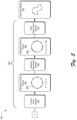
- FIG. 2 depicts an example system for generating a vector graphic from an input visual object according to the techniques described herein.
- FIG. 3 depicts an example system for generating a vector representation from an encoded latent representation of a raster path of a raster object.
- FIG. 4 depicts an example system for aspects of generating vector representations of visual objects.
- FIG. 5 depicts an example system illustrating example operation of a path decoder.
- FIG. 6 illustrates that the techniques for generating vector representations of visual objects described herein provide point-to-point correspondence between visual components across visual objects.
- FIG. 7 depicts an example procedure for generating vector representations of visual objects.
- FIG. 8 depicts an example procedure for generating a vector representation of a visual component of an input visual object.
- FIG. 9 depicts an example procedure for training a vector graphics system.
- FIG. 10 illustrates an example system including various components of an example device that are implementable as any type of computing device as described and/or utilized with reference to FIGS. 1 - 9 to implement aspects of the techniques described herein.
- generating vector representations of visual objects is leveraged in a digital medium environment. For instance, to mitigate the challenges of excessive burden on system resources experienced when generating vector representations of visual objects using conventional graphics editing systems, the described graphics editor system implements vector object generation techniques that reduce resource usage (e.g., memory and processor usage) in comparison with conventional vector object generation techniques, while providing high quality vector objects. Further, the described techniques are trainable using non-vector objects (e.g., raster images) and thus overcome the challenge of the lack of training data encountered in conventional techniques for generating vector graphics.
- resource usage e.g., memory and processor usage
- an encoder module encodes the raster object to generate a global latent code representation of the raster object.
- encoding the raster object includes representing each visual component of the raster object (e.g., primitives and/or sets of primitives) as a closed path, e.g., a curved line with connected endpoints.
- the global latent code includes encoded representations of a collection of visual components that combine to form the input raster object.
- a path decoder module decodes the global latent code to generate different path latent codes that each represent a respective visual component of the raster object. Each path latent code is then processed by a path decoder module to generate a vector representation of a respective visual component.
- the path decoder module starts with a data path representation for each path latent code (e.g., a circle) and places control points on the data path.
- a number of control points placed on the data path correlates to a geometric complexity of a visual component for each path latent code. For instance, more complex visual components are represented using more control points than less complex visual components.
- the path decoder module positionally adjusts at least some of the control points on the data path to enable the data path to be deformed to generate a corresponding vector representation. For instance, consider a visual component that includes different curves with different curvatures. In a data path representation of the visual component, control points are positionally adjusted on the data path to enable the data path to be deformed based on the curvature of the visual component. Accordingly, after adjusting at least some of the control points, the path decoder module deforms the data path relative to the control points to generate a vector representation of in input visual component. The path decoder module repeats this process for a set of path latent codes generated from the global latent code to generate a set of vector representations of visual components of the original raster object.
- a rasterizer module converts the vector representations into raster output and a compositor module arranges the raster output into a rasterized output object. For instance, as part of encoding the visual components into the global latent code, the visual components are labeled with position and depth information that describes coordinate position and visual depth of the visual components in the original input raster object. The compositor module utilizes this position and depth information to position the raster output into the rasterized output object to simulate the appearance of the original input raster object.
- the described techniques provide a vector representation of a raster object that obtains the desirable attributes of vector objects including compact data representations and increased visual fidelity during image scaling in comparison with non-vector graphics. Further, the described techniques overcome the challenge of a lack of vector-based training data by utilizing raster graphics for system training and without requiring vector image data for training.
- system resources e.g., memory and processor resources
- system resources e.g., memory and processor resources
- conventional graphics editing techniques for generating vector graphics that often inaccurately reproduce visual appearance of target objects and thus require manual input and system resources to correct the generated vector graphics.
- computationally efficient generation of vector graphics provided by the described techniques are leveraged to reduce resource inefficiency experienced in conventional graphics editing systems and thus increase system efficiency.
- image and “visual object” refer to digital visual content that is displayable and editable via a graphics editing system.
- visual objects include “input objects” such as raster images from which vector representations are generated, and “output objects” that are generated from vector representations of input objects.
- vector representation refers to vector data that is generated to represent an input object, such as a raster image.
- a vector representation for instance, is defined in terms of points on a Cartesian plane which are connected by lines and curves to form geometric primitives, polygons, and other shapes.
- a vector representation is convertible into a raster representation of an original input visual object.
- global latent code refers to an encoded version of an input visual object.
- An encoder e.g., a variational autoencoder (VAE)
- VAE variational autoencoder
- the global latent code describes visual components of an input visual object, such as visual primitives and/or sets of primitives that combine to form a visual appearance of the input visual object.
- path latent code refers to encoded versions of visual components of an input visual object that are extracted from a global latent code of the visual object. Each path latent code extracted from a global latent code, for instance, describes a different visual component of an input visual object.
- Example systems and procedures are then described which are performable in the example environment as well as other environments. Performance of the example systems and procedures is not limited to the example environment and the example environment is not limited to performance of the example systems and procedures. Finally, an example system and device are described that are representative of one or more computing systems and/or devices that are able to implement the various techniques described herein.
- FIG. 1 is an illustration of an environment 100 in an example implementation that is operable to employ generating vector representations of visual objects as described herein.
- the illustrated environment 100 includes a graphics editor system 102 that is leveraged to implement techniques for generating vector representations of visual objects described herein.
- the graphics editor system 102 is implemented by a client device 104 , a network graphics system 106 , and/or via interaction between the client device 104 and the network graphics system 106 .
- the client device 104 and the network graphics system 106 for example, are interconnected via a network 108 and thus are configured to communicate with one another to perform various aspects of generating vector representations of visual objects described herein.
- the network 108 represents a combination of wired and wireless networks and is implemented via any suitable architecture.
- Examples of computing devices that are used to implement the client device 104 and the network graphics system 106 include a desktop computer, a laptop computer, a mobile device (e.g., assuming a handheld configuration such as a tablet or mobile phone), a server device, and so forth. Additionally, the network graphics system 106 is implementable using a plurality of different devices, such as multiple servers utilized by an enterprise to perform operations “over the cloud” as further described in relation to FIG. 10 .
- the graphics editor system 102 includes a graphics editor module 110 that is representative of functionality to enable visual objects to be generated and edited in various ways. Accordingly, the graphics editor module 110 implements an editor graphical user interface (GUI) 112 and a vector graphics module 114 .
- GUI graphical user interface
- the editor GUI 112 represents functionality for receiving user interaction to perform various visual object editing actions, as well as to output visual indications of visual object editing actions.
- the vector graphics module 114 represents functionality for synthesizing vector-based graphics objects, such as utilizing techniques for generating vector representations of visual objects. In at least some implementations and as detailed below, the vector graphics module 114 leverages a set of machine learning algorithms for converting visual objects such as raster-based objects into corresponding vector objects.
- the graphics editor system 102 further includes visual object data 116 stored on a storage 118 .
- the visual object data 116 represents data that is utilized by and results from operation of the graphics editor module 110 .
- the visual object data 116 for instance, includes input objects 120 , vector representations 122 , and output objects 124 .
- the input objects 120 represent different visual objects that are generated in a variety of different ways, such as obtained from a visual object source (e.g., the network graphics system 106 ), generated via user interaction with the graphics editor module 110 , and so forth. Examples of the input objects 120 include graphical objects such as raster images, bitmap images, and so forth.
- the vector representations 122 correspond to vector representations of the input objects 120 generated by the vector graphics module 114 .
- the output objects 124 represent visual objects generated based on the vector representations 122 . In at least one implementation, the output objects 124 are generated by rasterizing instances of the vector representations 122 .
- the graphics editor system 102 includes a display device 126 which represents functionality for visual output of various aspects of techniques for generating vector representations of visual objects.
- the display device 126 for instance, outputs the editor GUI 112 , and is operable to receive user interaction to perform various aspects of the described techniques.
- a user for example, provides input to the editor GUI 112 to invoke the vector graphics module 114 .
- functionality of the vector graphics module 114 is automatically invocable (e.g., by the graphics editor module 110 ), such as in response to receiving and/or generating instances of the input objects 120 .
- the editor GUI 112 depicts different input objects 120 and output objects 124 generated by the vector graphics module 114 based on the input objects 120 .
- the vector graphics module 114 for example, generates different vector representations 122 based on the input objects and then generates the output objects 124 as visual depictions of the different vector representations.
- An input object 120 a for example, is input to the vector graphics module 114 and processed by the vector graphics module 114 to generate an output object 124 a .
- the output object 124 a results from utilizing the vector graphics module 114 to generate a vector representation 122 a of the input object 120 a and converting the vector representation 122 a into the output object 124 a as a reconstruction of the input object 120 a.
- input objects 120 b are processed by the vector graphics module 114 to generate vector representations 122 b of the input objects 120 b , which are utilized to generate output objects 124 b .
- the vector representations 122 b are generated by sampling different data values generated as part of vectorizing the input objects 120 b , e.g., from a latent space encoded from the input object 120 b .
- the vector representations 122 b are then utilized to generate the output objects 124 b .
- the input objects 120 b include a font set 128 that is used to generate the vector representations 122 b , and thus the output objects 124 b correspond to visual objects generated based on different vector representations 122 b generated from different instances of the font set 128 .
- an input object 120 c is processed by the vector graphics module 114 to generate vector representations 122 c which are then utilized to generate output objects 124 c .
- the vector representations 122 c are generated by interpolating on a latent space obtained from encoding the input object 120 c.
- FIGS. 2 - 6 depict different implementation details for generating vector representations of visual objects in accordance with one or more implementations.
- FIG. 2 depicts an example system 200 for generating a vector graphic from an input visual object according to the techniques described herein.
- the system 200 describes implementation of the vector graphics module 114 via various modules that perform different operations.
- the various modules discussed herein are implementable in hardware, firmware, software, and/or combinations thereof.
- the vector graphics module 114 receives an input object 120 d and an encoder module 202 encodes the input object 120 d to generate a global latent code 204 .
- the encoder module 202 is implemented as a variational autoencoder that maps the input object 120 a (e.g., a raster image) to a global latent variable z, e.g., the global latent code 204 .
- the architecture of the encoder module 202 includes five 2-dimensional convolutional residual blocks with [32, 64, 128, 256, 512] filters, respectively.
- the convolution layers have kernel size 3, stride 2 and zero pad the input by 1 pixel in both spatial dimensions from the input object 120 d .
- convolutional layers of the encoder module 202 are followed by two parallel fully connected layers that each output a vector of size 128 as part of the global latent code 204 .
- the global latent code 204 includes a set of T closed paths (e.g., sets of Bézier paths, Bézier curves) that combine to represent the input object 120 d.
- the global latent code 204 is input to a path generator module 206 which processes the global latent code 204 to generate path latent codes 208 .
- the path generator module 206 is implemented as a recurrent neural network (RNN). For instance, each of the T closed paths encoded by the encoder module 202 from the global latent variable z is decoded by the path generator module 206 to generate the path latent codes 208 .
- RNN recurrent neural network
- each of the T closed paths encoded by the encoder module 202 from the global latent variable z is decoded by the path generator module 206 to generate the path latent codes 208 .
- the path generator module 206 outputs a per-path latent code z t which combine to generate the path latent codes 208 .
- the path latent codes 208 are then individually processed by a path decoder module 210 to generate the vector representations 122 of the input object 120 d .
- the path decoder module 210 outputs a vector representation 122 as parameters of a closed path of arbitrary length, such as using a cubic Bézier segment. Operation of the path decoder module 210 is detailed below in FIGS. 3 and 5 .
- a rasterizer module 212 takes the vector representations 122 as input and rasterizes the vector representations 122 to generate raster output 214 .
- the rasterizer module 212 For example, for each vector representation 122 , the rasterizer module 212 generates a rasterized version of a closed path that represents a raster output 214 representation of the vector representation 122 .
- a compositor module 216 then takes the raster output 214 and composites the raster output 214 to generate an output object 124 d .
- the path generator module 206 generates the path latent codes 208 to include depth and position values for the path latent codes 208 . Accordingly, the compositor module 216 utilizes the depth and position values to place the closed curves from the raster output 214 in appropriate positions and depths to generate the output object 124 d.
- the vector graphics module 114 is trained end-to-end using the global latent code 204 obtained from the input object 120 a for 100-1000 epochs and using a batch size between 2-256. Further, to evaluate generalization to a variable number of segments by the path decoder module 210 , training includes randomly choosing a number of segments k ⁇ 7, . . . , 25 ⁇ at each training iteration. Thus, the described model is trained using the raster input object 120 d (e.g., as ground truth utilized for supervision) and without requiring vector-based supervision.
- FIG. 3 depicts an example system 300 for generating a vector representation from a data path representation of a visual component of an input object.
- the system 300 describes detailed operation of the path decoder module 210 .
- the path decoder module 210 takes a path latent code 208 as input and a control point module 302 generates sampled control points 304 for a data path described by the path latent code 208 .
- the control point module 302 predicts an optimal number of control points 304 to be used to represent the data path, such as based on a geometry of a visual component represented by the data path. Example operation of the control point module 302 is described below.
- An adaptive resampler module 306 takes the sampled control points 304 and positionally adjusts the control points 304 to generate adjusted control points 308 .
- the adaptive resampler module 306 processes the control points 304 to determine spatial locations of the control points 304 along the data path described by the path latent code 208 and positions each control point 304 at the determined spatial location to generate the adjusted control points 308 .
- a path deformation module 310 then processes the path latent code 208 to generate a vector representation 122 of the path latent code 208 .
- the path deformation module 310 for instance, deforms a data path described by the path latent code 208 and using the adjusted control points 308 to generate the vector representation 122 .
- the vector representation 122 is then utilized to generate an output object 124 as described throughout.
- FIG. 4 depicts an example system 400 for aspects of generating vector representations of visual objects described herein.
- the system 400 provides additional detail concerning operation of the system 200 introduced above.
- the input object 120 d is encoded by the encoder module 202 to generate the global latent code 204 , represented as z.
- the path generator module 206 then processes (e.g., decodes) the global latent code 204 to generate different path latent codes 208 , which in this example include path codes z 1 , z 2 , . . . z T .
- Each path latent code 208 is then decoded by the path decoder module 210 to generate a respective vector representation 122 .
- each vector representation 122 depict vector representations of visual components described by each path latent code 208 .
- each vector representation 122 represents a component of the input object 120 d , e.g., a vector representation of a raster-based component of the input object 120 d.
- the rasterizer module 212 takes the vector representations 122 as input and generates raster output 214 for each vector representation 122 , here represented as raster output L 1 , L 2 , . . . L T .
- each raster output 214 (L) includes depth information d, including d 1 , d 2 , . . . d T .
- the compositor module 216 composites the raster output 214 to generate the output object 124 d .
- the compositor module 216 for example, utilizes the depth information d as well as spatial coordinate information for each raster output 214 to generate the output object 124 d .
- the output object 124 d represents raster output of the vector representations 122 of the raster-based input object 120 d.
- each step in the system 400 is differentiable. Accordingly, as part of training the system 400 , a loss between input object 120 d and rasterized generated output object 124 d is calculated, and the calculated loss is backpropagated to train the system 400 using gradient descent. For instance, when output object 124 d is differentiated with respect to parameters of the corresponding vector representations 122 (e.g., Bézier parameters), the gradients have a small area of influence such as corresponding to support of a rasterization prefiltering kernel implemented by the rasterizer module 212 .
- parameters of the corresponding vector representations 122 e.g., Bézier parameters
- rasterizing the vector representations 122 at multiple resolutions. For instance, an image pyramid at different resolutions (e.g., different pixel resolutions) is rendered from the vector representations 122 instead of a single image, and the loss is calculated and aggregated at each pyramid level. Further, ground truth supervision is obtained for each
- the gradients at the coarsest level are more stable and provide a signal when the input object 120 d and the output object 124 d differ significantly, while the fine-scale gradients are usable in obtaining high spatial accuracy.
- the loss minimized is given by:
- FIG. 5 depicts a system 500 illustrating example operation of the path decoder module 210 .
- the control point module 302 takes a path latent code 208 (z t ) as input.
- the control point module 302 processes the path latent code 208 to generate sampled control points 304 for a data path 502 described by the path latent code 208 .
- the control point module 302 for instance, generates the sampled control points 304 as an optimal number of control points to be used to deform the data path 502 to visually represent a visual component described by the path latent code 208 .
- control point module 302 generates 3k control points along the data path 502 , with k representing a number of segments (e.g., cubic Bézier segments) along the data path 502 .
- k representing a number of segments (e.g., cubic Bézier segments) along the data path 502 .
- every third control point 304 represents an endpoint of a segment of the data path 502 .
- each of the sampled control points 304 is represented by z t , cartesian coordinates p i for the control point 304 , and a variable c i which distinguishes segment endpoints from other control points 304 .
- c i is implemented as a one-hot binary variable that identifies whether a particular control point 304 is an endpoint of a segment of the data path 502 or is a different type of control point, e.g., not a segment endpoint.
- each control point 304 is represented by a vector [p i , c i , z t ], i ⁇ 1, . . . , 3k ⁇ , which is referred to herein as a fused latent vector.
- the control point module 302 includes a neural network, such as a convolutional neural network (CNN).
- CNN convolutional neural network
- the control point module 302 is implemented with 4 fully connected layers with [256, 256, 256, 3] channels, respectively. Accordingly, to position the control points 304 on the path 502 , the control point module 302 places the control points 304 into a cyclic buffer which is then processed by the control point module 302 performing 1D convolutions with cyclic boundary conditions (along the sample dimension of the data path 502 ) to obtain spatial locations of the control points 304 along the data path 502 , represented as x 1 , . . . , x 3k . This cyclic convolution along a sample axis corresponds to convolution along the perimeter of the data path 502 .
- generating control points 304 along the data path 502 enables shape complexity (e.g., number of segments k) to be adjusted by changing control point density along the data path 502 .
- the control point module 302 is trained on a path latent variable z t to model a complexity-fidelity trade-off and automatically determine the optimal number of segments for a path, e.g., the data path 502 .
- the control point module 302 has 3 fully connected layers and outputs 3 parameters a, b, and c of a parametric curve x ⁇ ae ⁇ bx +c that approximates the loss graph of a given shape, with respect to the number of segments. Specifically, we solve for x in the derivative expression above and round up to obtain the number of segments k to sample.
- the control point module 302 is trainable separately from the end-to-end training of the overall vector graphics module 114 .
- determining a number of segments for a particular given path involves balancing the fidelity of the final deformation of the path to an original shape represented by the path latent variable z t .
- the control point module 302 is configured to determine a number of segments for the data path 502 utilizing a specified reconstruction loss that represents a variance of a deformed path from an original shape, e.g., the fidelity of the deformed path to the original shape. Accordingly, a default loss value can be utilized and/or a user is enabled to specify a desired loss value.
- a user specifies a level of fidelity based on a quality trade-off as a threshold on the derivative of the parametric curve above.
- a quality trade-off as a threshold on the derivative of the parametric curve above.
- this enables a user to consider whether higher fidelity and thus higher system resource consumption (e.g., processor bandwidth, memory, and so forth) is preferred, or lower fidelity and thus lower system resource consumption.
- the adaptive resampler module 306 takes the sampled control points 304 as input and positionally adjusts the control points 304 on the data path 502 to generate the adjusted control points 308 .
- the adaptive resampler module 306 is implemented as a 1D convolutional network with cyclic boundary condition acting on the fused latent vectors [p i , c i , z t ], where the p i are uniformly spaced along the path 502 as depicted in the sampled control points 304 .
- the adaptive resampler module 306 outputs a displacement ⁇ p i for each sampled point and this output is parameterized in polar coordinates so that p i + ⁇ p i remains on the data path 502 .
- the path deformation module 310 then operates on the fused latent vector with sample deformation [p i + ⁇ p i , c i , z t ], (e.g., instead of the regularly-spaced positions depicted in the sampled control points 304 ) to generate the decoded shape 312 .
- the decoded shape 312 is utilized to generate a corresponding vector representation 122 of a corresponding visual component (e.g., shape) from an input object 120 from the path latent code 208 a , e.g., z t .
- a corresponding visual component e.g., shape
- the path decoder module 210 is implemented as six 1D convolution layers with [170, 340, 340, 340, 340, 340, 2] channels. Further, the 1D convolutions have kernel size 3, stride 1 and circular padding of the input by 1 tap. Further, the adaptive resampler module 306 includes three 1D convolution layers with [340, 340, 1] channels, with the convolution layers having the same kernel size, stride and padding as the 1D convolution layers in the path decoder module 210 . In at least one implementation, the layers are followed by rectified linear activation function (ReLU) activations, except the last layer of the path decoder module 210 which is followed by a sigmoid activation.
- ReLU rectified linear activation function
- FIG. 6 illustrates that the techniques for generating vector representations of visual objects described herein provide point-to-point correspondence between shapes across visual objects.
- two shape sets 600 a , 600 b are depicted and are color coded to illustrate correspondence between different visual components (e.g., segments) of the individual shapes in the shape sets. Generally, this segmentation is captured when the shapes are encoded into a respective latent space z.
- the shape sets 600 represent sets of the output objects 124 .
- visual objects include objects made of a single path as in shape set 600 a or multiple paths as in shape set 600 b .
- the described techniques establish meaningful geometric correspondences between segments in each visual object, indicated by the red green blue (RGB) color coding.
- RGB red green blue
- the model's latent space capture correspondences between parts of the instance, such as the eyes and mouth of an emoji face as depicted in the shape set 600 b .
- the raster training dataset from an input object 120 is segmented and the segments are clustered across the dataset based on spatial position from the input object 120 .
- Each cluster is assigned a unique identifier across a set of shapes, which is shown in the shape sets 600 a , 600 b as corresponding RGB colors with each instance of an RGB color identifying a corresponding segment across each shape in a respective shape set 600 .
- this consistent segment labeling helps generate a more interpretable latent space for purposes of interpolation but is not required according to the described implementations.
- FIG. 7 depicts an example general method 700 for generating vector representations of visual objects.
- the method is performed by the graphics editor module 110 utilizing the vector graphics module 114 .
- Step 702 generates a global latent code of a raster-based input visual object by encoding visual components of the input visual object.
- the encoder module 202 for instance, encodes visual components of an input object 120 into the global latent code 204 .
- the visual components are encoded as vectors that represent closed data paths made up of sets of curves, e.g., Bézier curves.
- Step 704 generates path latent codes from the global latent code of the input visual object by decoding the global latent code into different individual path latent codes.
- the path generator module 206 decodes the global latent code 204 into different individual path latent codes 208 that each represent a different visual component of the input object 120 .
- Step 706 decodes the path latent codes into different respective vector representations of the visual components.
- the path decoder module 210 decodes each path latent code 208 into a respective vector representation 122 .
- generating the vector representations 122 from the path latent codes 208 includes: Step 708 generates, for each path latent code, a set of control points on a data path.
- the control point module 302 for example, generates a data representation of a data path (e.g., a circular path) and places control points along the data path, such as equidistant from one another along the data path.
- a number of control points generated along the data path for a particular path latent code 208 is determined based on a geometric and/or visual complexity of a particular visual component represented by the particular path latent code 208 . For instance, utilizing more control points enables more complex path deformations to be performed.
- Step 710 adjusts, for each path latent code, control points on a respective data path based on a geometry of a visual component represented by the path latent code.
- the adaptive resampler module 306 adjusts a position of at least some control points on a data path to enable the data path to simulate a geometry of a respective visual component.
- Step 712 deforms, for each path latent code, a data path relative to the control points to generate a respective vector representation. For example, the path deformation module 310 deforms each data path about the adjusted control points to cause the data path to simulate a visual component represented by the data path.
- Step 714 generates an output visual object by converting the vector representations into respective raster representations.
- the rasterizer module 212 converts the vector representations 122 into respective raster output 214 and the compositor module 216 composites the raster output 214 into an output object 124 .
- Individual raster representations of the raster output 214 include position information (e.g., position coordinates) and depth information (e.g., z values) such that the compositor module 216 places the raster representations in appropriate positions and depths as part of the output object 124 .
- the output object 124 is displayed on a display device, such as part of the editor GUI 112 of the graphics editor module 110 .
- FIG. 8 depicts an example method 800 for generating a vector representation of a visual component of an input visual object in accordance with one or more implementations.
- Step 802 determines a geometry of a visual component of an input visual object represented by a particular path latent code.
- the control point module 302 determines a geometry of a particular visual component represented by a path latent code 208 .
- a visual component is represented as a geometric primitive and/or set of primitives.
- a geometry of a visual component refers to a shape and visual arrangement of the visual component, such as curves, lines, and/or angles that combine to form the visual component.
- Step 804 determines a number of control points for a data path to represent the visual component based on a geometric complexity of the geometry. For instance, the control point module 302 determines a number of control points to be placed on a data path representation of a visual component to correspond to a geometric complexity.
- a simple visual component such as a straight line, for instance, utilizes fewer control points (e.g., 3 control points) than a more geometrically complex visual component, such as a visual component that includes multiple different angles and/or changes in curvature.
- Step 806 positions the control points on the data path representation of the visual component.
- the control point module 302 places the control points equidistantly from one another along the data path and labels each control point as either a segment endpoint or not a segment endpoint.
- Step 808 positionally adjusts a set of the control points on the data path based on the geometry of the visual component.
- the adaptive resampler module 306 positions control points at portions of the data path that correlate to geometrically complex sections of the visual component, such as sections that have changes in angle and/or multiple different angles. In at least one implementation this is performed by generating displacement values for the set of control points and positionally adjusting the set of control points on the data path based on respective displacement values.
- Step 810 deforms the data path relative to the control points to generate a vector representation of the visual component.
- the path deformation module 310 deforms the data path about the control points such as by manipulating individual control points to change curvature of segments of the data path to simulate the geometry (e.g., visual appearance) of the visual component. Accordingly, the vector representation is then usable to combine with other vector representations of visual components to generate an output object 124 .
- FIG. 9 depicts an example method 900 for training a vector graphics system in accordance with one or more implementations.
- the method for example, is implementable to train the vector graphics module 114 to generate vector representations of input objects 120 .
- Step 902 causes a vector graphics system to convert individual vector representations of visual components of an input object into respective raster representations of different resolution levels.
- the vector graphics module 114 for instance, implements the rasterizer module 212 to convert individual vector representations 122 into respective raster representations of different visual resolution levels. Generally, this enables the vector graphics module 114 to obtain raster representations of individual vector representations 122 at multiple different resolution levels.
- a hierarchical data structure e.g., a pyramid
- each level of the hierarchical structure is populated with a different respective raster representation of a particular resolution.
- the hierarchical structure is traversable to obtain raster representations of the vector representation at different resolutions.
- Step 904 calculates a loss value between each of the raster representations at the different visual resolution levels and the input object.
- the vector graphics module 114 calculates a loss value between each of the raster representations at the different visual resolution levels and a visual component of the input visual object represented by the raster representations.
- Step 906 backpropagates the loss values through the vector graphics system to minimize a loss between the output visual object and the input visual object.
- the vector graphics module 114 backpropagates the loss values through the system to minimize a loss between an output object 124 and a corresponding input object 120 .
- this increases a visual fidelity of an output object 124 to a corresponding input object 120 .
- any services, components, modules, methods, and/or operations described herein are able to be implemented using software, firmware, hardware (e.g., fixed logic circuitry), manual processing, or any combination thereof.
- Some operations of the described methods, for example, are described in the general context of executable instructions stored on computer-readable storage memory that is local and/or remote to a computer processing system, and implementations include software applications, programs, functions, and the like.
- any of the functionality described herein is performable, at least in part, by one or more hardware logic components, such as, and without limitation, Field-programmable Gate Arrays (FPGAs), Application-specific Integrated Circuits (ASICs), Application-specific Standard Products (ASSPs), System-on-a-chip systems (SoCs), Complex Programmable Logic Devices (CPLDs), and the like.
- FPGAs Field-programmable Gate Arrays
- ASICs Application-specific Integrated Circuits
- ASSPs Application-specific Standard Products
- SoCs System-on-a-chip systems
- CPLDs Complex Programmable Logic Devices
- FIG. 10 illustrates an example system 1000 that includes an example computing device 1002 that is representative of one or more computing systems and/or devices that are usable to implement the various techniques described herein. This is illustrated through inclusion of the graphics editor module 110 .
- the computing device 1002 includes, for example, a server of a service provider, a device associated with a client (e.g., a client device), an on-chip system, and/or any other suitable computing device or computing system.
- the example computing device 1002 as illustrated includes a processing system 1004 , one or more computer-readable media 1006 , and one or more I/O interfaces 1008 that are communicatively coupled, one to another.
- the computing device 1002 further includes a system bus or other data and command transfer system that couples the various components, one to another.
- a system bus includes any one or combination of different bus structures, such as a memory bus or memory controller, a peripheral bus, a universal serial bus, and/or a processor or local bus that utilizes any of a variety of bus architectures.
- a variety of other examples are also contemplated, such as control and data lines.
- the processing system 1004 is representative of functionality to perform one or more operations using hardware. Accordingly, the processing system 1004 is illustrated as including hardware elements 1010 that are be configured as processors, functional blocks, and so forth. This includes example implementations in hardware as an application specific integrated circuit or other logic device formed using one or more semiconductors.
- the hardware elements 1010 are not limited by the materials from which they are formed or the processing mechanisms employed therein.
- processors are comprised of semiconductor(s) and/or transistors (e.g., electronic integrated circuits (ICs)).
- processor-executable instructions are, for example, electronically-executable instructions.
- the computer-readable media 1006 is illustrated as including memory/storage 1012 .
- the memory/storage 1012 represents memory/storage capacity associated with one or more computer-readable media.
- the memory/storage 1012 includes volatile media (such as random access memory (RAM)) and/or nonvolatile media (such as read only memory (ROM), Flash memory, optical disks, magnetic disks, and so forth).
- the memory/storage 1012 includes fixed media (e.g., RANI, ROM, a fixed hard drive, and so on) as well as removable media (e.g., Flash memory, a removable hard drive, an optical disc, and so forth).
- the computer-readable media 1006 is configurable in a variety of other ways as further described below.
- Input/output interface(s) 1008 are representative of functionality to allow a user to enter commands and information to computing device 1002 , and also allow information to be presented to the user and/or other components or devices using various input/output devices.
- input devices include a keyboard, a cursor control device (e.g., a mouse), a microphone, a scanner, touch functionality (e.g., capacitive or other sensors that are configured to detect physical touch), a camera (e.g., which employs visible or non-visible wavelengths such as infrared frequencies to recognize movement as gestures that do not involve touch), and so forth.
- Examples of output devices include a display device (e.g., a monitor or projector), speakers, a printer, a network card, tactile-response device, and so forth.
- a display device e.g., a monitor or projector
- speakers e.g., speakers
- a printer e.g., a printer
- network card e.g., a network card
- tactile-response device e.g., tactile-response device
- modules include routines, programs, objects, elements, components, data structures, and so forth that perform particular tasks or implement particular abstract data types.
- module generally represent software, firmware, hardware, or a combination thereof.
- the features of the techniques described herein are platform-independent, meaning that the techniques are implementable on a variety of commercial computing platforms having a variety of processors.
- Implementations of the described modules and techniques are storable on or transmitted across some form of computer-readable media.
- the computer-readable media includes a variety of media that that is accessible to the computing device 1002 .
- computer-readable media includes “computer-readable storage media” and “computer-readable signal media.”
- Computer-readable storage media refers to media and/or devices that enable persistent and/or non-transitory storage of information in contrast to mere signal transmission, carrier waves, or signals per se. Thus, computer-readable storage media refers to non-signal bearing media.
- the computer-readable storage media includes hardware such as volatile and non-volatile, removable and non-removable media and/or storage devices implemented in a method or technology suitable for storage of information such as computer readable instructions, data structures, program modules, logic elements/circuits, or other data.
- Examples of computer-readable storage media include, but are not limited to, RAM, ROM, EEPROM, flash memory or other memory technology, CD-ROM, digital versatile disks (DVD) or other optical storage, hard disks, magnetic cassettes, magnetic tape, magnetic disk storage or other magnetic storage devices, or other storage device, tangible media, or article of manufacture suitable to store the desired information and which are accessible to a computer.
- Computer-readable signal media refers to a signal-bearing medium that is configured to transmit instructions to the hardware of the computing device 1002 , such as via a network.
- Signal media typically embodies computer readable instructions, data structures, program modules, or other data in a modulated data signal, such as carrier waves, data signals, or other transport mechanism.
- Signal media also include any information delivery media.
- modulated data signal means a signal that has one or more of its characteristics set or changed in such a manner as to encode information in the signal.
- communication media include wired media such as a wired network or direct-wired connection, and wireless media such as acoustic, RF, infrared, and other wireless media.
- hardware elements 1010 and computer-readable media 1006 are representative of modules, programmable device logic and/or fixed device logic implemented in a hardware form that is employable in some embodiments to implement at least some aspects of the techniques described herein, such as to perform one or more instructions.
- Hardware includes components of an integrated circuit or on-chip system, an application-specific integrated circuit (ASIC), a field-programmable gate array (FPGA), a complex programmable logic device (CPLD), and other implementations in silicon or other hardware.
- ASIC application-specific integrated circuit
- FPGA field-programmable gate array
- CPLD complex programmable logic device
- hardware operates as a processing device that performs program tasks defined by instructions and/or logic embodied by the hardware as well as a hardware utilized to store instructions for execution, e.g., the computer-readable storage media described previously.
- software, hardware, or executable modules are implementable as one or more instructions and/or logic embodied on some form of computer-readable storage media and/or by one or more hardware elements 1010 .
- the computing device 1002 is configured to implement particular instructions and/or functions corresponding to the software and/or hardware modules.
- implementation of a module that is executable by the computing device 1002 as software is achieved at least partially in hardware, e.g., through use of computer-readable storage media and/or hardware elements 1010 of the processing system 1004 .
- the instructions and/or functions are executable/operable by one or more articles of manufacture (for example, one or more computing devices 1002 and/or processing systems 1004 ) to implement techniques, modules, and examples described herein.
- the techniques described herein are supportable by various configurations of the computing device 1002 and are not limited to the specific examples of the techniques described herein. This functionality is also implementable entirely or partially through use of a distributed system, such as over a “cloud” 1014 as described below.
- the cloud 1014 includes and/or is representative of a platform 1016 for resources 1018 .
- the platform 1016 abstracts underlying functionality of hardware (e.g., servers) and software resources of the cloud 1014 .
- the resources 1018 include applications and/or data that are utilized while computer processing is executed on servers that are remote from the computing device 1002 .
- the resources 1018 also include services provided over the Internet and/or through a subscriber network, such as a cellular or Wi-Fi network.
- the platform 1016 abstracts the resources 1018 and functions to connect the computing device 1002 with other computing devices.
- the platform 1016 also serves to abstract scaling of resources to provide a corresponding level of scale to encountered demand for the resources that are implemented via the platform. Accordingly, in an interconnected device embodiment, implementation of functionality described herein is distributable throughout the system 1000 . For example, the functionality is implementable in part on the computing device 1002 as well as via the platform 1016 that abstracts the functionality of the cloud 1014 .
Landscapes
- Engineering & Computer Science (AREA)
- Physics & Mathematics (AREA)
- Theoretical Computer Science (AREA)
- General Physics & Mathematics (AREA)
- Mathematical Physics (AREA)
- Data Mining & Analysis (AREA)
- General Engineering & Computer Science (AREA)
- Software Systems (AREA)
- Computing Systems (AREA)
- Evolutionary Computation (AREA)
- Biophysics (AREA)
- General Health & Medical Sciences (AREA)
- Molecular Biology (AREA)
- Computational Linguistics (AREA)
- Biomedical Technology (AREA)
- Artificial Intelligence (AREA)
- Life Sciences & Earth Sciences (AREA)
- Health & Medical Sciences (AREA)
- Computational Mathematics (AREA)
- Mathematical Analysis (AREA)
- Mathematical Optimization (AREA)
- Pure & Applied Mathematics (AREA)
- Algebra (AREA)
- Databases & Information Systems (AREA)
- Computer Hardware Design (AREA)
- Geometry (AREA)
- Probability & Statistics with Applications (AREA)
- Image Processing (AREA)
Abstract
Description
where
Claims (20)
Priority Applications (1)
| Application Number | Priority Date | Filing Date | Title |
|---|---|---|---|
| US17/166,937 US12073153B2 (en) | 2021-02-03 | 2021-02-03 | Generating vector representations of visual objects |
Applications Claiming Priority (1)
| Application Number | Priority Date | Filing Date | Title |
|---|---|---|---|
| US17/166,937 US12073153B2 (en) | 2021-02-03 | 2021-02-03 | Generating vector representations of visual objects |
Publications (2)
| Publication Number | Publication Date |
|---|---|
| US20220245296A1 US20220245296A1 (en) | 2022-08-04 |
| US12073153B2 true US12073153B2 (en) | 2024-08-27 |
Family
ID=82612515
Family Applications (1)
| Application Number | Title | Priority Date | Filing Date |
|---|---|---|---|
| US17/166,937 Active 2043-07-01 US12073153B2 (en) | 2021-02-03 | 2021-02-03 | Generating vector representations of visual objects |
Country Status (1)
| Country | Link |
|---|---|
| US (1) | US12073153B2 (en) |
Families Citing this family (2)
| Publication number | Priority date | Publication date | Assignee | Title |
|---|---|---|---|---|
| CN116206013B (en) * | 2022-09-09 | 2026-04-03 | 南京工业大学 | Pattern Reconstruction Method Based on Adaptive Transformation of Primitive Space Relationships |
| IL297653B2 (en) * | 2022-10-25 | 2024-03-01 | Geox Gis Innovations Ltd | A system and method for segment-aware semantic segmentation |
-
2021
- 2021-02-03 US US17/166,937 patent/US12073153B2/en active Active
Non-Patent Citations (43)
| Title |
|---|
| "Artistic Glyph Image Synthesis via One-Stage Few-Shot Learning", arXiv Preprint, arXiv.org [retrieved Mar. 12, 2021]. Retrieved from the Internet <https://arxiv.org/pdf/1910.04987.pdf>., May 19, 2020, 12 pages. |
| "CairoSVG", Kozea Group, GitHub, Inc. [retrieved Mar. 2, 2021]. Retrieved from the Internet <https://github.com/Kozea/CairoSVG>., Sep. 27, 2018, 2 pages. |
| "Creative Stall", Noun Project Inc. Website [retrieved Mar. 2, 2021]. Retrieved from the Internet <https://thenounproject.com/creativestall/>., 3 pages. |
| "Noto-emoji", Google Fonts, GitHub Website [retrieved Apr. 12, 2021]. Retrieved from the Internet <https://github.com/googlefonts/noto-emoji>., Sep. 29, 2015, 4 pages. |
| Alexandre Carlier et al., "DeepSVG: A Hierarchical Generative Network for Vector Graphics Animation", dated Oct. 22, 2020, 19 pages, https://arxiv.org/pdf/2007.11301.pdf (Year: 2020). * |
| Azadi, Samaneh et al., "Multi-Content GAN for Few-Shot Font Style Transfer", Proceedings of the IEEE Conference on Computer Vision and Pattern Recognition (CVPR) [retrieved Mar. 2, 2021]. Retrieved from the Internet <https://openaccess.thecvf.com/content_cvpr_2018/papers/Azadi_Multi-Content_GAN_for_CVPR_2018_paper.pdf>., Dec. 1, 2017, 10 pages. |
| Bessmeltsev, Mikhail et al., "Vectorization of Line Drawings via PolyVector Fields", arXiv Preprint, arXiv.org [retrieved Mar. 2, 2021]. Retrieved from the Internet <https://arxiv.org/pdf/1801.01922.pdf>., Sep. 5, 2018, 12 pages. |
| Carlier, Alexandre et al., "DeepSVG: A Hierarchical Generative Network for Vector Graphics Animation", arXiv Preprint, arXiv.org [retrieved Mar. 2, 2021]. Retrieved from the Internet <https://arxiv.org/pdf/2007.11301.pdf>., Oct. 22, 2020, 19 pages. |
| Dominici, Edoardo A. , "PolyFit: perception-aligned vectorization of raster clip-art via intermediate polygonal fitting", ACM Transactions on Graphics, vol. 39, No. 4, Article No. 77 [retrieved Mar. 2, 2021]. Retrieved from the Internet <https://open.library.ubc.ca/cIRcle/collections/ubctheses/24/items/1.0389752>., Apr. 2020, 57 pages. |
| Egiazarian, Vage et al., "Deep Vectorization of Technical Drawings", arXiv Preprint, arXiv.org [retrieved Mar. 9, 2021]. Retrieved from the Internet <https://arxiv.org/pdf/2003.05471.pdf>., Jun. 30, 2020, 41 pages. |
| Ellis, Kevin et al., "Learning to Infer Graphics Programs from Hand-Drawn Images", Advances in neural information processing systems 31 [retrieved Dec. 10, 2020]. Retrieved from the Internet <https://par.nsf.gov/servlets/purl/10088909>., Dec. 2017, 10 pages. |
| Favreau, Jean-Dominique et al., "Fidelity vs. Simplicity: a Global Approach to Line Drawing Vectorization", ACM Transactions on Graphics, Association for Computing Machinery, 2016, Proceedings of SIGGRAPH 2016 [retrieved Mar. 9, 2021]. Retrieved from the Internet <https://hal.inria.fr/hal-01309271/file/fidelity_simplicity.pdf>., Jul. 2016, 11 pages. |
| Ganin, Yaroslav et al., "Synthesizing Programs for Images using Reinforced Adversarial Learning", arXiv Preprint, arXiv.org [retrieved Mar. 9, 2021]. Retrieved from the Internet <https://arxiv.org/pdf/1804.01118.pdf>., Apr. 3, 2018, 12 pages. |
| Gao, Jun et al., "DeepSpline: Data-Driven Reconstruction of Parametric Curves and Surfaces", arXiv Preprint, arXiv.org [retrieved Mar. 9, 2021]. Retrieved from the Internet <https://arxiv.org/pdf/1901.03781.pdf>., Jan. 12, 2019, 13 pages. |
| Groueix, Thibault et al., "A Papier-Mache Approach to Learning 3D Surface Generation", 2018 IEEE/CVF Conference on Computer Vision and Pattern Recognition [retrieved Mar. 12, 2021]. Retrieved from the Internet <https://openaccess.thecvf.com/content_cvpr_2018/papers_backup/Groueix_A_Papier-Mache_Approach_CVPR_2018_paper.pdf>., Jun. 2018, 9 pages. |
| Guo, Yi et al., "Deep Line Drawing Vectorization via Line Subdivision and Topology Reconstruction", Computer Graphics Forum, vol. 38, No. 7 [retrieved Mar. 12, 2021]. Retrieved from the Internet <https://chuhan89.com/publication/guo-2019-deep/guo-2019-deep.pdf>., Nov. 14, 2019, 10 pages. |
| Ha, David et al., "A Neural Representation of Sketch Drawings", arXiv Preprint, arXiv.org [retrieved Mar. 18, 2021]. Retrieved from the Internet <https://arxiv.org/pdf/1704.03477.pdf>., May 19, 2017, 15 pages. |
| He, Kaiming et al., "Deep Residual Learning for Image Recognition", arXiv Preprint, arXiv.org [retrieved Mar. 18, 2021]. Retrieved from the Internet <https://arxiv.org/pdf/1512.03385.pdf>., Dec. 10, 2015, 12 pages. |
| Hoshyari, Shayan et al., "Perception-Driven Semi-Structured Boundary Vectorization", ACM Transactions on Graphics, vol. 37, No. 4, Article No. 118 [retrieved Mar. 18, 2021]. Retrieved from the Internet <https://www.ics.uci.edu/˜majumder/vispercep/perception-driven-vectorization.pdf>., Jul. 2018, 14 pages. |
| Huang, Zhewei et al., "Learning to Paint With Model-Based Deep Reinforcement Learning", arXiv Preprint, arXiv.org [retrieved Mar. 18, 2021]. Retrieved from the Internet <https://arxiv.org/pdf/1903.04411.pdf>., Aug. 16, 2019, 11 pages. |
| Jayaraman, Pradeep K. et al., "UV-Net: Learning from Curve-Networks and Solids", arXiv Preprint, arXiv.org [retrieved Mar. 25, 2021]. Retrieved from the Internet <https://arxiv.org/pdf/2006.10211.pdf>., Jun. 18, 2020, 15 pages. |
| Kopf, Johannes et al., "Depixelizing Pixel Art", Proceedings of ACM Transactions on Graphics (TOG), vol. 30 Issue 4 [retrieved Mar. 25, 2021]. Retrieved from the Internet, <https://www.researchgate.net/profile/Dani- Lischinski/publication/220184192_Depixelizing_Pixel_Art/links/02e7e516bb52d7eff9000000/Depixelizing-Pixel-Art.pdf>., Jul. 1, 2011, 8 pages. |
| Lecun, Yann et al., "The MNIST Database of handwritten digits", [retrieved Apr. 6, 2021]. Retrieved from the Internet <http://yann.lecun.com/exdb/mnist/>., 1999, 7 pages. |
| Li, Tzu-Mao et al., "Differentiable Vector Graphics Rasterization for Editing and Learning", ACM Transactions on Graphics, vol. 39, No. 6 [retrieved Apr. 6, 2021]. Retrieved from the Internet <https://dl.acm.org/doi/pdf/10.1145/3414685.3417871>., Nov. 2020, 15 pages. |
| Liu, Chen et al., "Raster-to-Vector: Revisiting Floorplan Transformation", 2017 IEEE International Conference on Computer Vision (ICCV) [retrieved Apr. 6, 2021]. Retrieved from the Internet, <https://www.researchgate.net/profile/Jiajun-Wu-7/publication/322059565_Raster-to-Vector_Revisiting_Floorplan_Transformation/links/5bbab9e5299bf1049b748fdf/Raster-to-Vector-Revisiting-Floorplan-Transformation.pdf>., Oct. 2017, 9 pages. |
| Lopes, Raphael G. et al., "A Learned Representation for Scalable Vector Graphics", 2019 IEEE/CVF International Conference on Computer Vision (ICCV), vol. 1 [Apr. 12, 2021]. Retrieved from the Internet <https://openaccess.thecvf.com/content_ICCV_2019/papers/Lopes_A_Learned_Representation_for_Scalable_Vector_Graphics_ICCV_2019_paper.pdf>., Nov. 2019, 10 pages. |
| Nakano, Reiichiro , "Neural Painters: A learned differentiable constraint for generating brushstroke paintings", arXiv Preprint, Cornell University, arXiv.org [retrieved Apr. 12, 2021]. Retrieved from the Internet <https://arxiv.org/pdf/1904.08410.pdf>., Apr. 22, 2019, 15 pages. |
| Paschalidou, Despoina et al., "Superquadrics Revisited: Learning 3D Shape Parsing Beyond Cuboids", arXiv Preprint, Cornell University, arXiv.org [retrieved Apr. 12, 2021]. Retrieved from the Internet <https://arxiv.org/pdf/1904.09970.pdf>., <https://openaccess.thecvf.com/content_CVPR_2019/papers/Paschalidou_Superquadrics_Revisited_Learning_3D_Shape_Parsing_Beyond_Cuboids_CVPR_2019_paper.pdf>., Apr. 22, 2019, 21 pages. |
| Raphael Gontijo Lopes et al. "A Learned Representation for Scalable Vector Graphics", 2019, https://openaccess.thecvf.com/content_ICCV_2019/papers/Lopes_A_Learned_Representation_for_Scalable_Vector_Graphics_ICCV_2019_paper.pdf, 10 pages (Year: 2019). * |
| Reddy, Pradyumna et al., "Discovering Pattern Structure Using Differentiable Compositing", arXiv Preprint, Cornell University, arXiv.org [retrieved Apr. 12, 2021]. Retrieved from the Internet <https://arxiv.org/pdf/2010.08788.pdf>., Oct. 17, 2020, 15 pages. |
| Ribeiro, Leo Sampaio F. et al., "Sketchformer: Transformer-based Representation for Sketched Structure", arXiv Preprint, Cornell University, arXiv.org [retrieved Apr. 12, 2021]. Retrieved from the Internet <https://arxiv.org/pdf/2002.10381.pdf>., 028/2482020, 9 pages. |
| Schuster, Mike et al., "Bidirectional Recurrent Neural Networks", IEEE Transactions on Signal Processing, vol. 45, No. 11 [retrieved Apr. 12, 2021]. Retrieved from the Internet <https://cin.ufpe.br/˜fnj/RNA/BRNN.pdf>., Nov. 1997, 9 pages. |
| Selinger, Peter , "Potrace: a polygon-based tracing algorithm", [retrieved Apr. 12, 2021]. Retrieve from the Internet <https://citeseerx.ist.psu.edu/viewdoc/download?doi=10.1.1.159.5801&rep=rep1&type=pdf>., Sep. 20, 2003, 16 pages. |
| Sharma, Gopal et al., "CSGNet: Neural Shape Parser for Constructive Solid Geometry", arXiv Preprint, Cornell University, arXiv.org [retrieved Apr. 12, 2021]. Retrieved from the Internet <https://arxiv.org/pdf/1712.08290.pdf>., Mar. 31, 2018, 16 pages. |
| Simonyan, Karen et al., "Very Deep Convolutional Networks for Large-Scale Image Recognition", arXiv Preprint, Cornell University, arXiv.org [retrieved Apr. 12, 2021]. Retrieved from the Internet <https://arxiv.org/pdf/1409.1556.pdf>., Sep. 2014, 14 pages. |
| Sinha, Ayan et al., "SurfNet: Generating 3D Shape Surfaces Using Deep Residual Networks", arXiv Preprint, Cornell University, arXiv.org [retrieved Apr. 13, 2021]. Retrieved from the Internet <https://arxiv.org/pdf/1703.04079.pdf>., Mar. 12, 2017, 10 pages. |
| Smirnov, Dmitriy et al., "Deep Parametric Shape Predictions using Distance Fields", arXiv Preprint, Cornell University, arXiv.org [retrieved Apr. 13, 201]. Retrieved from the Internet <https://arxiv.org/pdf/1904.08921.pdf>., Mar. 19, 2020, 14 pages. |
| Smirnov, Dmitriy et al., "Learning Manifold Patch-Based Representations of Man-Made Shapes", arXiv Preprint, Cornell University, arXiv.org [retrieved Apr. 13, 2021]. Retrieved from the Internet <https://arxiv.org/pdf/1906.12337.pdf>., Jun. 28, 2019, 24 pages. |
| Sutton, Richard S. et al., "Policy Gradient Methods for Reinforcement Learning with Function Approximation and Action-Dependent Baselines", NIPS'99: Proceedings of the 12th International Conference on Neural Information Processing Systems [retrieved Apr. 13, 2021]. Retrieved from the Internet <https://proceedings.neurips.cc/paper/1999/file/464d828b85b0bed98e80ade0a5c43b0f-Paper.pdf>., Nov. 1999, pp. 1057-1063. |
| Tong, Qianqian et al., "Calibrating the Adaptive Learning Rate to Improve Convergence of Adam", arXiv Preprint, Cornell Univeristy, arXiv.org [retrieved Apr. 13, 2021]. Retrieved from the Internet <https://arxiv.org/pdf/1908.00700.pdf>., Sep. 11, 2019, 50 pages. |
| Tulsiani, Shubham et al., "Learning Shape Abstractions by Assembling Volumetric Primitives", 2017 IEEE Conference on Computer Vision and Pattern Recognition (CVPR) [retrieved Apr. 13, 2021]. Retrieved from the Internet <https://openaccess.thecvf.com/content_cvpr_2017/papers/Tulsiani_Learning_Shape_Abstractions_CVPR_2017_paper.pdf>., Jul. 2017, 9 pages. |
| Zheng, Ningyuan et al., "StrokeNet: A Neural Painting Environment", 2019 International Conference on Learning Representations [retrieved Apr. 13, 2021]. Retrieved from the Internet <https://openreview.net/pdf?id=HJxwDiActX>., Sep. 27, 2018, 12 pages. |
| Zou, Chuhang et al., "3D-PRNN: Generating Shape Primitives with Recurrent Neural Networks", 2017 IEEE International Conference on Computer Vision (ICCV) [retrieved Apr. 13, 2021]. Retrieved from the Internet <https://openaccess.thecvf.com/content_ICCV_2017/papers/Zou_3D-PRNN_Generating_Shape_ICCV_2017_paper.pdf>., Oct. 2017, pp. 900-909. |
Also Published As
| Publication number | Publication date |
|---|---|
| US20220245296A1 (en) | 2022-08-04 |
Similar Documents
| Publication | Publication Date | Title |
|---|---|---|
| US11694334B2 (en) | Segmenting objects in vector graphics images | |
| Reddy et al. | Im2vec: Synthesizing vector graphics without vector supervision | |
| US12118669B2 (en) | Subdividing a three-dimensional mesh utilizing a neural network | |
| AU2019202799B2 (en) | A method to automatically predict handle locations for skinningtransformations using deep learning | |
| US12299939B2 (en) | Generating novel images using sketch image representations | |
| CN101536078B (en) | Improving image masks | |
| JP5045619B2 (en) | Image processing apparatus and method, and program | |
| US10943375B2 (en) | Multi-state vector graphics | |
| US12536715B2 (en) | Generation of stylized drawing of three- dimensional shapes using neural networks | |
| US10846889B2 (en) | Color handle generation for digital image color gradients using machine learning | |
| US11769279B2 (en) | Generative shape creation and editing | |
| US12482151B2 (en) | Stroke-guided sketch vectorization | |
| US11314400B2 (en) | Unified digital content selection system for vector and raster graphics | |
| US12073153B2 (en) | Generating vector representations of visual objects | |
| US20240303908A1 (en) | Multiresolution deep implicit functions for three-dimensional shape representation | |
| US11200708B1 (en) | Real-time color vector preview generation | |
| US20230110114A1 (en) | Generating scalable fonts utilizing multi-implicit neural font representations | |
| US20260065533A1 (en) | Mask conditioned image transformation based on a text prompt | |
| US11392806B2 (en) | Differentiable rasterizer for vector font generation and editing | |
| US12229892B2 (en) | Visualizing vector graphics in three-dimensional scenes | |
| US20260017865A1 (en) | Parametric hair model for digital hair generation | |
| AU2019213404B2 (en) | Unified selection model for vector and raster graphics | |
| US12417570B2 (en) | Vectorizing by piecewise deconstruction of object strokes | |
| CN121639855B (en) | Thangka generation method based on structure and pattern double-channel constraint diffusion model | |
| US20250124212A1 (en) | Vector font generation based on cascaded diffusion |
Legal Events
| Date | Code | Title | Description |
|---|---|---|---|
| FEPP | Fee payment procedure |
Free format text: ENTITY STATUS SET TO UNDISCOUNTED (ORIGINAL EVENT CODE: BIG.); ENTITY STATUS OF PATENT OWNER: LARGE ENTITY |
|
| AS | Assignment |
Owner name: ADOBE INC., CALIFORNIA Free format text: ASSIGNMENT OF ASSIGNORS INTEREST;ASSIGNORS:GHARBI, MICHAEL YANIS;MITRA, NILOY JYOTI;LUKAC, MICHAL;AND OTHERS;SIGNING DATES FROM 20210201 TO 20210202;REEL/FRAME:055213/0258 |
|
| FEPP | Fee payment procedure |
Free format text: PETITION RELATED TO MAINTENANCE FEES GRANTED (ORIGINAL EVENT CODE: PTGR); ENTITY STATUS OF PATENT OWNER: LARGE ENTITY |
|
| STPP | Information on status: patent application and granting procedure in general |
Free format text: DOCKETED NEW CASE - READY FOR EXAMINATION |
|
| STPP | Information on status: patent application and granting procedure in general |
Free format text: NOTICE OF ALLOWANCE MAILED -- APPLICATION RECEIVED IN OFFICE OF PUBLICATIONS |
|
| STPP | Information on status: patent application and granting procedure in general |
Free format text: PUBLICATIONS -- ISSUE FEE PAYMENT RECEIVED |
|
| STPP | Information on status: patent application and granting procedure in general |
Free format text: PUBLICATIONS -- ISSUE FEE PAYMENT VERIFIED |
|
| STCF | Information on status: patent grant |
Free format text: PATENTED CASE |