US12073080B2 - System and method for improving reliability of a data storage system - Google Patents
System and method for improving reliability of a data storage system Download PDFInfo
- Publication number
- US12073080B2 US12073080B2 US17/691,595 US202217691595A US12073080B2 US 12073080 B2 US12073080 B2 US 12073080B2 US 202217691595 A US202217691595 A US 202217691595A US 12073080 B2 US12073080 B2 US 12073080B2
- Authority
- US
- United States
- Prior art keywords
- data
- compression
- packets
- format
- literal
- Prior art date
- Legal status (The legal status is an assumption and is not a legal conclusion. Google has not performed a legal analysis and makes no representation as to the accuracy of the status listed.)
- Active, expires
Links
Images


Classifications
-
- G—PHYSICS
- G06—COMPUTING OR CALCULATING; COUNTING
- G06F—ELECTRIC DIGITAL DATA PROCESSING
- G06F3/00—Input arrangements for transferring data to be processed into a form capable of being handled by the computer; Output arrangements for transferring data from processing unit to output unit, e.g. interface arrangements
- G06F3/06—Digital input from, or digital output to, record carriers, e.g. RAID, emulated record carriers or networked record carriers
- G06F3/0601—Interfaces specially adapted for storage systems
- G06F3/0602—Interfaces specially adapted for storage systems specifically adapted to achieve a particular effect
- G06F3/061—Improving I/O performance
- G06F3/0613—Improving I/O performance in relation to throughput
-
- H—ELECTRICITY
- H03—ELECTRONIC CIRCUITRY
- H03M—CODING; DECODING; CODE CONVERSION IN GENERAL
- H03M7/00—Conversion of a code where information is represented by a given sequence or number of digits to a code where the same, similar or subset of information is represented by a different sequence or number of digits
- H03M7/30—Compression; Expansion; Suppression of unnecessary data, e.g. redundancy reduction
- H03M7/3084—Compression; Expansion; Suppression of unnecessary data, e.g. redundancy reduction using adaptive string matching, e.g. the Lempel-Ziv method
- H03M7/3086—Compression; Expansion; Suppression of unnecessary data, e.g. redundancy reduction using adaptive string matching, e.g. the Lempel-Ziv method employing a sliding window, e.g. LZ77
-
- G—PHYSICS
- G06—COMPUTING OR CALCULATING; COUNTING
- G06F—ELECTRIC DIGITAL DATA PROCESSING
- G06F3/00—Input arrangements for transferring data to be processed into a form capable of being handled by the computer; Output arrangements for transferring data from processing unit to output unit, e.g. interface arrangements
- G06F3/06—Digital input from, or digital output to, record carriers, e.g. RAID, emulated record carriers or networked record carriers
- G06F3/0601—Interfaces specially adapted for storage systems
- G06F3/0602—Interfaces specially adapted for storage systems specifically adapted to achieve a particular effect
- G06F3/0608—Saving storage space on storage systems
-
- G—PHYSICS
- G06—COMPUTING OR CALCULATING; COUNTING
- G06F—ELECTRIC DIGITAL DATA PROCESSING
- G06F3/00—Input arrangements for transferring data to be processed into a form capable of being handled by the computer; Output arrangements for transferring data from processing unit to output unit, e.g. interface arrangements
- G06F3/06—Digital input from, or digital output to, record carriers, e.g. RAID, emulated record carriers or networked record carriers
- G06F3/0601—Interfaces specially adapted for storage systems
- G06F3/0628—Interfaces specially adapted for storage systems making use of a particular technique
- G06F3/0638—Organizing or formatting or addressing of data
-
- G—PHYSICS
- G06—COMPUTING OR CALCULATING; COUNTING
- G06F—ELECTRIC DIGITAL DATA PROCESSING
- G06F3/00—Input arrangements for transferring data to be processed into a form capable of being handled by the computer; Output arrangements for transferring data from processing unit to output unit, e.g. interface arrangements
- G06F3/06—Digital input from, or digital output to, record carriers, e.g. RAID, emulated record carriers or networked record carriers
- G06F3/0601—Interfaces specially adapted for storage systems
- G06F3/0628—Interfaces specially adapted for storage systems making use of a particular technique
- G06F3/0655—Vertical data movement, i.e. input-output transfer; data movement between one or more hosts and one or more storage devices
- G06F3/0658—Controller construction arrangements
-
- G—PHYSICS
- G06—COMPUTING OR CALCULATING; COUNTING
- G06F—ELECTRIC DIGITAL DATA PROCESSING
- G06F3/00—Input arrangements for transferring data to be processed into a form capable of being handled by the computer; Output arrangements for transferring data from processing unit to output unit, e.g. interface arrangements
- G06F3/06—Digital input from, or digital output to, record carriers, e.g. RAID, emulated record carriers or networked record carriers
- G06F3/0601—Interfaces specially adapted for storage systems
- G06F3/0628—Interfaces specially adapted for storage systems making use of a particular technique
- G06F3/0655—Vertical data movement, i.e. input-output transfer; data movement between one or more hosts and one or more storage devices
- G06F3/0659—Command handling arrangements, e.g. command buffers, queues, command scheduling
-
- G—PHYSICS
- G06—COMPUTING OR CALCULATING; COUNTING
- G06F—ELECTRIC DIGITAL DATA PROCESSING
- G06F3/00—Input arrangements for transferring data to be processed into a form capable of being handled by the computer; Output arrangements for transferring data from processing unit to output unit, e.g. interface arrangements
- G06F3/06—Digital input from, or digital output to, record carriers, e.g. RAID, emulated record carriers or networked record carriers
- G06F3/0601—Interfaces specially adapted for storage systems
- G06F3/0668—Interfaces specially adapted for storage systems adopting a particular infrastructure
- G06F3/0671—In-line storage system
- G06F3/0673—Single storage device
-
- H—ELECTRICITY
- H03—ELECTRONIC CIRCUITRY
- H03M—CODING; DECODING; CODE CONVERSION IN GENERAL
- H03M7/00—Conversion of a code where information is represented by a given sequence or number of digits to a code where the same, similar or subset of information is represented by a different sequence or number of digits
- H03M7/30—Compression; Expansion; Suppression of unnecessary data, e.g. redundancy reduction
- H03M7/3084—Compression; Expansion; Suppression of unnecessary data, e.g. redundancy reduction using adaptive string matching, e.g. the Lempel-Ziv method
-
- H—ELECTRICITY
- H03—ELECTRONIC CIRCUITRY
- H03M—CODING; DECODING; CODE CONVERSION IN GENERAL
- H03M7/00—Conversion of a code where information is represented by a given sequence or number of digits to a code where the same, similar or subset of information is represented by a different sequence or number of digits
- H03M7/30—Compression; Expansion; Suppression of unnecessary data, e.g. redundancy reduction
- H03M7/40—Conversion to or from variable length codes, e.g. Shannon-Fano code, Huffman code, Morse code
- H03M7/4031—Fixed length to variable length coding
Definitions
- the present invention relates to data compression in a storage system.
- LZ4 algorithm is a reversible data compression algorithm known for a very high calculation speed thereof.
- This algorithm is a kind of dictionary compression called Lempel-Ziv (LZ) method.
- LZ Lempel-Ziv
- the copy code is a code obtained by replacing a certain character string with distance and length information when the certain character string has appeared before
- the literal code is a code obtained by outputting a character string in which a copy code is not found in a non-compressed manner. That is, in the dictionary type compression algorithm, data strings in which each literal code and each copy code are integrated are alternately arranged in data to be compressed.
- Non-PTL 1 compressed data in the LZ4 algorithm has a format in which a packet including one set of a literal code and a copy code one by one is output as one unit.
- a storage system includes an interface and a controller.
- the controller includes a compression circuit configured to generate compressed data by compressing received data received via the interface, and a decompression circuit that decompresses the compressed data before storing the compressed data in a storage drive to confirm data consistency.
- the compression circuit sequentially executes a compression task of the received data, sequentially generates packets of the compressed data, and transfers the packets to the decompression circuit.
- the decompression circuit decompresses the received packet in parallel with the compression task.
- FIG. 1 shows an example of an overall configuration of a storage system to which a data compression system is applied according to a first embodiment.
- FIG. 2 shows an example of a host write processing flow of the storage system according to the first embodiment.
- FIG. 3 shows an example of a data flow of host write processing of the storage system according to the first embodiment.
- FIG. 4 shows an example of a data structure with a integrity code in write processing of the storage system according to the first embodiment.
- FIG. 5 shows an example of a flowchart of processing of performing a decompression check on compressed data according to the first embodiment.
- FIG. 6 shows an example of an internal block of a compression and decompression circuit of the storage system according to the first embodiment.
- FIG. 7 shows an example of a parallel operation of a circuit that performs decompression check on compressed data according to the first embodiment.
- FIG. 8 shows a general LZ4 format according to a second embodiment.
- FIG. 9 shows an example of a general LZ4 compressed data pattern according to the second embodiment.
- FIG. 10 shows an LZ4 format according to the second embodiment of the invention.
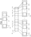
- FIG. 11 shows an example of the LZ4 compressed data pattern according to the second embodiment of the invention.
- FIG. 12 is a diagram showing details of a literal code length section of the LZ4 format according to the second embodiment.
- FIG. 13 shows an example of a flowchart of compression processing for each packet of LZ4 according to the second embodiment of the invention.
- FIG. 14 shows an LZ4 format according to a third embodiment of the invention.
- FIG. 15 shows a flowchart of compression processing for each packet of LZ4 according to the third embodiment of the invention.
- processing may be described with a “program” as a subject, since a program is executed by a processor (for example, a central processing unit (CPU)), predetermined processing is appropriately performed using a storage device (for example, a memory) and/or an interface device (a communication port), and thus a subject of the processing may be described as a processor.
- a processor for example, a central processing unit (CPU)
- predetermined processing is appropriately performed using a storage device (for example, a memory) and/or an interface device (a communication port)
- a subject of the processing may be described as a processor.
- the processing described using the program as the subject may be processing performed by a computer (for example, a calculation host or a storage device) including a processor.
- a computer for example, a calculation host or a storage device
- the term “controller” may refer to a processor or a hardware circuit that performs a part or all of processing performed by the processor.
- the program may be installed in each computer from a program source (for example, a program distribution server or a storage medium readable by a computer), and in this case, the program distribution server may include a CPU and a storage resource, the storage resource may further store a distribution program and a program to be distributed, and the CPU of the program distribution server may distribute the program to be distributed to another computer by executing the distribution program.
- a program source for example, a program distribution server or a storage medium readable by a computer
- the program distribution server may include a CPU and a storage resource
- the storage resource may further store a distribution program and a program to be distributed
- the CPU of the program distribution server may distribute the program to be distributed to another computer by executing the distribution program.
- the storage system described below has a data compression function.
- the storage system compresses received data to generate compressed data, and stores the compressed data in a storage drive.
- the storage system decompresses the compressed data before storing the decompressed data in the storage drive, and checks consistency between pre-compression data and the decompressed data. Thereby, high reliability can be ensured.
- the storage system includes a compression circuit that compresses data and a decompression circuit that decompresses the compressed data. These can be operated in parallel.
- the compression circuit sequentially generates packets of compressed data and transmits the packets to the decompression circuit.
- the decompression circuit executes the decompression processing of the packets in parallel with the compression processing of the compression circuit. Accordingly, it is possible to prevent deterioration of compression throughput including decompression check after the data compression, and to guarantee predetermined write performance of the storage system.
- FIG. 1 shows an example of an overall configuration of a storage system with a compression function according to an embodiment of the description.
- a storage system 101 has a dual controller configuration in which a storage controller 112 and a storage controller 122 are mounted.
- the storage controller 112 is connected to a host interface (I/F) 111 , communicates with a host (not shown), includes a switch 117 , and communicates with a plurality of storage drives 102 .
- a storage drive 102 for example, a hard disk drive (HDD) or a solid state drive (SSD), which is a nonvolatile storage drive, can be used.
- HDD hard disk drive
- SSD solid state drive
- the storage controller 112 further includes a CPU 113 for controlling data transmitted to and received from the host and the storage system 101 , a memory 114 of the CPU 113 , and a switch 115 for connecting the storage controller 112 and the storage controller 122 .
- the CPU 113 is a processor, includes one or a plurality of cores, and implements a predetermined function by operating in accordance with a program stored in the memory 114 .
- a volatile memory such as a DRAM can be used as the memory 114 .
- the storage controller 112 further includes a compression and decompression circuit 116 and is connected to the switch 115 .
- the storage controller 122 includes a switch 127 , a CPU 123 , a memory 124 , a switch 125 , and a compression and decompression circuit 126 .
- the compression and decompression circuit 126 may be mounted in a drive box (not shown) accommodating the storage drive 102 .
- FIG. 2 shows an operation flow of the host write processing including the compression function operation of the storage system 101 .
- FIG. 3 shows a data flow in the storage system 101 shown in the processing flow of FIG. 2 .
- the CPU 113 of the storage controller 112 stores plaintext write data from the host I/F 111 into the memory 114 (step 201 in FIG. 2 ).
- the CPU 113 duplicates the plaintext write data stored in the memory 114 in the memory 124 of the storage controller 122 through the switch 115 , the switch 125 , and the CPU 123 (step 202 in FIG. 2 ).
- the CPU 113 transfers the plaintext write data stored in the memory 114 to the compression and decompression circuit 116 through the switch 115 , and the compression and decompression circuit 116 compresses the transferred data (step 203 in FIG. 2 ).
- the compression and decompression circuit 116 returns the compressed write data to the memory 114 of the storage controller 112 , and at the same time, transfers the compressed write data to the memory 124 of the storage controller 122 to perform duplication (step 204 in FIG. 2 ).
- the CPU 113 writes the compressed write data stored in the memory 114 into the storage drive 102 through the switch 117 (step 205 in FIG. 2 ).
- FIG. 4 shows user data and a integrity code assigned to the user data in the storage system 101 .
- the integrity code 402 is added as 8B for each 512B of user data 401 .
- the storage system 101 receives the user data 401 from the host, and adds the integrity code 402 to the user data 401 via the host I/F 111 of the data flow 301 .
- FIG. 5 shows a processing flow of performing decompression check processing of compressed data inside the compression and decompression circuit 116 when the compression function is operated in the host write processing of the storage system 101 .
- decompression check processing consistency between the decompressed data and the pre-compression data is confirmed.
- the user data to which the integrity code is added is plaintext write data to be compressed and decompressed by the compression and decompression circuit 116 .
- step 501 the compression and decompression circuit 116 removes the integrity code of the plaintext write data and extracts only the user data to be compressed.
- step 502 the compression and decompression circuit 116 compresses the plaintext write data.
- the compressed data is output in units of packets.
- step 503 the compression and decompression circuit 116 decompresses the compressed data for each packet.
- the compression and decompression circuit 116 repeats compression and decompression in units of packets, and determines in step 504 whether similar processing was completed for all plaintext write data. When the processing is not completed ( 504 : NO), the flow returns to step 502 .
- step 505 the compression and decompression circuit 116 performs verification processing to determine whether the decompressed data matches original plaintext write data.
- the compression and decompression circuit 116 outputs the compressed data in step 507 , and completes the decompression check processing of the compressed data.
- the compression and decompression circuit 116 returns an error response in step 508 , and completes the decompression check processing of the compressed data.
- FIG. 6 shows an example of an internal circuit configuration of the compression and decompression circuit 116 .
- the compression and decompression circuit 116 includes an I/F 601 , a compression unit 602 , a decompression unit 603 , a comparison unit 604 , a determination unit 605 , and signal lines 611 to 615 .
- the compression unit (compression circuit) 602 , the decompression unit (decompression circuit) 603 , the comparison unit 604 , and the determination unit 605 are mounted as different circuits.
- the I/F 601 transmits a plaintext to the compression unit 602 through the signal line 611 .
- the compression unit 602 compresses the data and outputs the compressed data to the decompression unit 603 through the signal line 612 .
- the decompression unit 603 decompresses the compressed data and outputs the decompressed data to the comparison unit 604 through the signal line 613 .
- the comparison unit 604 receives the plaintext before compression from the I/F 601 through the signal line 611 , and further compares the plaintext with the decompressed data received from the decompression unit 603 through the signal line 613 to confirm the match between the data.
- the comparison unit 604 further outputs the result of the comparison of the data to the determination unit 605 through the signal line 614 .
- the determination unit 605 receives a confirmation result of the comparison unit 604 .
- the determination unit 605 confirms that the data match
- the determination unit 605 outputs the compressed data received from the compression unit 602 through the signal line 612 to the I/F 601 through the signal line 615 .
- the determination unit 605 returns an error response to the I/F 601 through the signal line 615 .
- FIG. 7 is a time chart when the compression unit 602 and the decompression unit 603 are operated in parallel.
- the compression unit 602 outputs the compressed data divided into units of packets in a stepwise manner.
- a task 701 indicates time until the first packet of the compressed data is output.
- the compression unit 602 starts a task 702 indicating compression processing of a next packet.
- the first packet of the compressed data is passed to the decompression unit 603 , and the task 702 of the compression unit 602 and a task 711 of the decompression unit 603 operate in parallel.
- the compression unit 602 completes the processing of the task 702
- the compression unit 602 starts the task 703
- the decompression unit 603 starts the task 712
- the compression unit 602 and the decompression unit 603 operate in parallel.
- the present embodiment includes the compression unit and the decompression unit that can operate independently, and executes the compression processing and the decompression processing in units of packets. Accordingly, the compression unit and the decompression unit are operated in parallel, and a total processing time of the compression unit and the decompression unit can be shortened.
- LZ4 will be described as an example of a data compression algorithm.
- FIG. 8 shows an LZ4 format that is used as a standard.
- the LZ4 format that is used as a standard is referred to as a standard LZ4.
- the compressed data of the standard LZ4 is divided into units of packets, and each packet is output as soon as compression of each packet is completed.
- the packet 801 is one packet of the standard LZ4 format.
- a literal code and a copy code is stored in the packet 801 one by one.
- the literal code is obtained by encoding a character string of the user data as it is, and the copy code is a code indicating repetitive data in the user data.
- a specific data section in a packet will be described below.
- a token section 802 is a 1-byte section where length information of each of the literal code and the copy code is four bits. The length information of the code stored in the token section 802 can be stored up to a code length of up to 15 characters for each of the literal code and the copy code.
- a literal character section 804 is a data section in which the literal characters of the literal codes are stored in a non-compressed manner as many as the sum of the lengths of the literal codes stored in the token section 802 and the literal code length section 803 .
- distance information of the copy code is stored in 2 bytes.
- a portion indicating information of the literal code is a literal code unit
- a portion indicating information of the copy code is a copy code unit.
- the literal code unit includes a part of the token section 802 , the literal code length section 803 , and the literal character section 804 .
- the copy code unit includes another part of the token section 802 , the copy distance section 805 , and the copy code length section 806 .
- FIG. 9 shows a compressed data pattern when user data 901 is compressed by the standard LZ4.
- the user data 901 is data obtained by removing the integrity code 402 from the plaintext write data and extracting and aligning only the user data 401 .
- the user data 901 has a format in which literal code sections 902 A, 902 B, and 902 C and copy code sections 903 A, 903 B, and 903 C are alternately aligned according to the principle of dictionary compression.
- the literal code does not necessarily exist between the copy code sections. For example, there is a case where the literal code section 902 B does not exist in the user data 901 , and the copy code sections 903 A and 903 B are continuous.
- the user data 901 divided into the literal code section and the copy code section is encoded into compressed data of the standard LZ4, the user data 901 is divided into packet units of the packets 801 A, 801 B, and 801 C.
- the packet 801 A includes one literal code section 902 A and one copy code section 903 A for a section obtained by dividing the user data 901 into a literal code section and a copy code section. Since the same applies to the packet 801 B and the packet 801 C, the description thereof will be omitted. However, as described above, when there is a data section in which the copy code sections are continuous in the user data 901 , the packet 801 of the standard LZ4 does not include the literal code, and only the copy code section is encoded and stored.
- parallel operability of the compression unit 602 and the decompression unit 603 is further enhanced by limiting a processing amount per packet in the compression in step 502 in the first embodiment.
- FIG. 10 shows packets 1001 and 1011 conforming to these two packet formats.
- LZ4 format newly defined in the present embodiment is referred to as LZ4 according to the present embodiment.
- the LZ4 according to the present embodiment is characterized in that an upper limit value is set to the literal code length in the packet.
- a difference between the packet 801 of the standard LZ4 and the packet 1001 of the first format of the LZ4 of the present embodiment is as follows.
- the upper limit value is not set to the literal code length of the literal code length section 803 of the packet 801 .
- the upper limit value is set to the literal code length of a literal code length section 1003 in the packet 1001 .
- the other sections in the packet have the same format.
- the packet 1011 of a second format of LZ4 defines a “dummy copy code”, which is a code indicating that nothing is copied (no copy), in the standard LZ4 packet format.
- the dummy copy code is configured with, for example, the copy distance section 805 , and the copy distance area 805 indicates 0.
- the copy distance section 805 and the copy code length section 806 may be configured, and both the copy distance section 805 and the copy code length section 806 may indicate 0.
- a compressed data packet is output according to the second format indicated by the packet 1011 .
- the dummy copy code is a portion indicating the second format.
- the character (literal code) of the defined upper limit value is stored in the literal code length section 1003 and is output. That is, in the packet 1011 , since all of the consecutive literal code sections in the user data cannot be completely contained in the packet, the separation of the packet is expressed by the dummy copy code 1015 to which nothing is copied, and the packet 1011 is output. Then, in the compression processing of generating the next packet, the encoding is performed from the literal code which is not yet encoded in the middle of the user data.
- FIG. 11 shows a compressed data pattern when the user data 901 is compressed by LZ4 according to the present embodiment.
- a group 1101 of packets is a form indicating a pattern of packets of data compressed by LZ4 according to the present embodiment.
- the group 1101 of packets includes the plurality of aligned packets 1011 and the packet 1001 at an end position.
- the user data 901 When the user data 901 is divided by the LZ4 code section according to the present embodiment, the user data 901 includes the literal code section in which a literal code section 1111 A to a literal code section 1111 B having a literal code upper limit value of LZ4 of the present embodiment as a data length are continuously arranged, and then includes a literal code section 1111 C in which a data length is equal to or less than an upper limit value of one packet, and a copy code section 1111 D.
- a packet 1011 A encodes the literal code section 1111 A of the user data 901 .
- a packet 1011 B encodes the literal code section 1111 B of the user data 901 .
- Several packets 1011 having a fixed literal code length and a dummy copy code are arranged between the packets 1011 A and 1011 B.
- a packet 1001 A encodes the literal code section 1111 C having a data length equal to or less than the upper limit of the literal code length and the copy code section 1111 D included in LZ4 of the present embodiment.
- a group 1101 A of packets includes several packets 1011 from the packet 1011 A to the packet 1011 B, and the packet 1001 A.
- the group 1101 of packets is a group of packets each including one literal code and one copy code.
- the entire compressed data has a format in which the formats of the group 1101 of packets are sequentially arranged.
- the group 1101 of packets may have a configuration in which only one packet 1001 is included depending on the pattern of the user data 901 to be compressed.
- FIG. 12 is a detailed description of a data format of the token section 802 and the literal code length section 803 .
- an upper 4-bit data section 1201 is a section indicating the literal code length
- a lower 4-bit data section 1202 is a section indicating the copy code length.
- the data section 1201 is referred to as a token literal code length section 1201
- the data section 1202 is referred to as a token copy code length section 1202 .
- the literal code length section 803 is not inserted into the packet 801 .
- the literal code length 803 is inserted.
- literal code length section 803 the data length is added one byte at a time.
- a literal code length byte 1203 A is the first byte added to the literal code length section 803 .
- the literal code length byte 1203 A can express up to the number of characters of one byte, that is, 255 characters.
- literal code length section 803 data of one byte is added to the literal code length section 803 for every 255 characters of a continuous literal code.
- a literal code length byte 1203 C when all the bits of the one-byte section are not filled with “1”, the literal code length byte 1203 C is regarded as the end of the data section of the literal code length section 803 .
- a maximum value that can be taken without adding the literal code length byte 1203 to the next section is a bit string “1111 1110”.
- the maximum number of bytes of the literal code length section 1003 is set to 1
- the only component of the literal code length section 1003 is a literal code length byte 1204 .
- the literal code length byte 1204 has the best code efficiency when the maximum value is set to “1111 1110”.
- FIG. 13 shows a detailed compression processing flow per packet in step 502 of FIG. 5 when LZ4 of the present embodiment is used in the compression unit 602 of the compression and decompression circuit 116 .
- the compression unit 602 reads the plaintext write data from a next position of the position encoded in previous packet, and detects the code.
- the compression unit 602 determines whether the detected code is a literal code or a copy code.
- the compression unit 602 calculates the literal code and encodes the literal code in the section indicating the literal code of the packet 1001 or the packet 1011 .
- the compression unit 602 writes a code indicating that the literal code length is 0 in the token literal code length section 1201 , calculates the copy code, and encodes the copy code in the section indicating the copy code of the packet 1001 .
- the compression unit 602 determines whether the literal code length of the remaining data to be encoded exceeds the upper limit literal code length set in the packet in step 1304 .
- the compression unit 602 detects and encodes the copy code.
- the copy code is encoded in step 1305 , the compressed data packet is output in the format of the packet 1001 .
- the compression unit 602 encodes the dummy copy code.
- the compressed data packet is output in the format of the packet 1011 .
- each packet of the compressed data in the LZ4 algorithm is output within a certain period of time, and the parallel operability of the compression unit 602 and the decompression unit 603 can be enhanced.
- the LZ4 format of the present embodiment has a small change from the standard LZ4 as described above, the LZ4 format can be implemented with a few man-hours for mounting.
- the storage system 101 may monitor the compression processing in the compression and decompression circuits 116 and 126 and change the upper limit literal code length based on the compression processing performance.
- the CPUs 113 and 123 monitor a compression rate and/or a compression speed in the compression and decompression circuits 116 and 126 , and manage the information in the memories 114 and 124 .
- a circuit for changing the upper limit literal code length may be incorporated in the compression and decompression circuits 116 and 126 .
- the CPU 113 or 123 calculates statistical values of the compression rate and/or the compression speed of both of the compression and decompression circuits 116 and 126 at a predetermined timing.
- the statistical value may be, for example, an average value. For example, when the calculated compression rate is less than a threshold, the CPU 113 or 123 increases the upper limit value by a predetermined number. Alternatively, when the calculated compression speed is less than a threshold, the CPU 113 or 123 decreases the upper limit value by a predetermined number.
- the compression unit sequentially generates packets such that at least a part of the packets has a size equal to or smaller than a preset upper limit value.
- the upper limit value is set to the literal code length.
- a part in which the upper limit value is set may be appropriately set in accordance with a packet format and a system design.
- a higher compression rate is realized by changing the format of the LZ4 packet of the second embodiment. Changes from the second format of LZ4 and the compression processing flow according to the second embodiment will be described below with reference to FIGS. 14 and 15 .
- FIG. 14 is a second format of LZ4 defined in a third embodiment.
- the literal code length does not become the upper limit value, and there is no change point in the packet 1001 in which the literal code and the copy code are stored.
- the dummy copy code is not defined for the packet 1011 , and the packet 1401 is configured by three data sections of the token section 802 , the literal code length section 1003 , and the literal character section 804 .
- the token copy code length section 1202 in the token section 802 indicates whether a copy code is stored in the packet. That is, when the copy code length indicated by the token copy code length section 1202 is 0, it indicates that the copy code is not stored in the packet. As described above, a packet separation position can be determined with reference to the token copy code length section 1202 .
- the token copy code length section 1202 is a portion indicating the second format.
- FIG. 15 is a processing flow at the time of packet compression in the LZ4 format defined in the third embodiment.
- the determination in step 1304 is YES, no further encoding is performed, a process 1501 is passed, and the compression processing of the packet is ended.
- the invention is not limited to the above-descried embodiments, and includes various modifications.
- the embodiments described above are described in detail for easy understanding of the invention, and the invention is not necessarily limited to those including all the configurations described above.
- a part of a configuration of one embodiment can be replaced with a configuration of another embodiment, and the configuration of another embodiment can be added to the configuration of one embodiment.
- a part of the configuration of one embodiment may be added, deleted, or replaced with another configuration.
- the configurations, functions, processing units, processing means, or the like may be implemented by hardware by designing a part or all of them with, for example, an integrated circuit.
- the above-described configurations, functions, and the like may also be implemented by software by interpreting and executing a program that implements the functions using a processor.
- Information such as a program, a table, and a file for realizing each function can be placed in a recording device such as a memory, a hard disk, or a solid state drive (SSD), or in a recording medium such as an IC card, an SD card, or a DVD.
- SSD solid state drive
- control lines and signal lines show those considered to be necessary for the description, and not all the control lines and the signal lines are necessarily shown on the product. In practice, it may be considered that almost all the configurations are connected to each other.
Landscapes
- Engineering & Computer Science (AREA)
- Theoretical Computer Science (AREA)
- Human Computer Interaction (AREA)
- Physics & Mathematics (AREA)
- General Engineering & Computer Science (AREA)
- General Physics & Mathematics (AREA)
- Compression, Expansion, Code Conversion, And Decoders (AREA)
- Memory System (AREA)
Abstract
Description
Claims (8)
Applications Claiming Priority (2)
| Application Number | Priority Date | Filing Date | Title |
|---|---|---|---|
| JP2021186159A JP7475319B2 (en) | 2021-11-16 | 2021-11-16 | STORAGE SYSTEM AND DATA PROCESSING METHOD THEREIN |
| JP2021-186159 | 2021-11-16 |
Publications (2)
| Publication Number | Publication Date |
|---|---|
| US20230152972A1 US20230152972A1 (en) | 2023-05-18 |
| US12073080B2 true US12073080B2 (en) | 2024-08-27 |
Family
ID=86324592
Family Applications (1)
| Application Number | Title | Priority Date | Filing Date |
|---|---|---|---|
| US17/691,595 Active 2042-03-10 US12073080B2 (en) | 2021-11-16 | 2022-03-10 | System and method for improving reliability of a data storage system |
Country Status (3)
| Country | Link |
|---|---|
| US (1) | US12073080B2 (en) |
| JP (1) | JP7475319B2 (en) |
| CN (1) | CN116136741A (en) |
Families Citing this family (2)
| Publication number | Priority date | Publication date | Assignee | Title |
|---|---|---|---|---|
| US12197419B2 (en) * | 2022-09-14 | 2025-01-14 | Sap Se | Consistency checks for compressed data |
| JP2024165412A (en) * | 2023-05-17 | 2024-11-28 | 日立ヴァンタラ株式会社 | Storage Systems |
Citations (5)
| Publication number | Priority date | Publication date | Assignee | Title |
|---|---|---|---|---|
| US5155484A (en) * | 1991-09-13 | 1992-10-13 | Salient Software, Inc. | Fast data compressor with direct lookup table indexing into history buffer |
| JPH0855063A (en) | 1994-08-10 | 1996-02-27 | Hitachi Ltd | Data guarantee method for storage device |
| US5877711A (en) | 1997-09-19 | 1999-03-02 | International Business Machines Corporation | Method and apparatus for performing adaptive data compression |
| US5968149A (en) * | 1998-01-07 | 1999-10-19 | International Business Machines Corporation | Tandem operation of input/output data compression modules |
| WO2005026925A2 (en) | 2002-05-21 | 2005-03-24 | Washington University | Intelligent data storage and processing using fpga devices |
Family Cites Families (4)
| Publication number | Priority date | Publication date | Assignee | Title |
|---|---|---|---|---|
| JP2000339842A (en) | 1999-05-28 | 2000-12-08 | Nec Ibaraki Ltd | Magnetic tape control device |
| DE10131801B4 (en) | 2001-06-30 | 2013-03-07 | Robert Bosch Gmbh | Method for data compression and navigation system |
| WO2018061161A1 (en) | 2016-09-29 | 2018-04-05 | 株式会社日立製作所 | Storage apparatus and method for controlling same |
| US10476518B1 (en) | 2018-12-06 | 2019-11-12 | Nyquist Semiconductor Limited | Hardware friendly data compression |
-
2021
- 2021-11-16 JP JP2021186159A patent/JP7475319B2/en active Active
-
2022
- 2022-03-10 US US17/691,595 patent/US12073080B2/en active Active
- 2022-08-16 CN CN202210978639.1A patent/CN116136741A/en not_active Withdrawn
Patent Citations (9)
| Publication number | Priority date | Publication date | Assignee | Title |
|---|---|---|---|---|
| US5155484A (en) * | 1991-09-13 | 1992-10-13 | Salient Software, Inc. | Fast data compressor with direct lookup table indexing into history buffer |
| JPH0855063A (en) | 1994-08-10 | 1996-02-27 | Hitachi Ltd | Data guarantee method for storage device |
| US5877711A (en) | 1997-09-19 | 1999-03-02 | International Business Machines Corporation | Method and apparatus for performing adaptive data compression |
| JPH11196000A (en) | 1997-09-19 | 1999-07-21 | Internatl Business Mach Corp <Ibm> | Coding method and data compressor |
| US5968149A (en) * | 1998-01-07 | 1999-10-19 | International Business Machines Corporation | Tandem operation of input/output data compression modules |
| JP2000188553A (en) | 1998-01-07 | 2000-07-04 | Internatl Business Mach Corp <Ibm> | Data compression system |
| WO2005026925A2 (en) | 2002-05-21 | 2005-03-24 | Washington University | Intelligent data storage and processing using fpga devices |
| JP2006526227A (en) | 2003-05-23 | 2006-11-16 | ワシントン ユニヴァーシティー | Intelligent data storage and processing using FPGA devices |
| US20070277036A1 (en) | 2003-05-23 | 2007-11-29 | Washington University, A Corporation Of The State Of Missouri | Intelligent data storage and processing using fpga devices |
Non-Patent Citations (2)
| Title |
|---|
| Japanese Office Action issued on Jan. 9, 2024 for Japanese Patent Application No. 2021-186159. |
| Jeehong Kim and Jundong Cho. 2019., Hardware accelerated Fast Lossless Compression Based on LZ4 Algorithm. In Proceedings of the 2019 3rd International Conference on Digital Signal Processing (ICDSP 2019) Association for Computing Machinery, New York, NY, USA, 65-68. |
Also Published As
| Publication number | Publication date |
|---|---|
| US20230152972A1 (en) | 2023-05-18 |
| CN116136741A (en) | 2023-05-19 |
| JP2023073606A (en) | 2023-05-26 |
| JP7475319B2 (en) | 2024-04-26 |
Similar Documents
| Publication | Publication Date | Title |
|---|---|---|
| CN101930418B (en) | Multiple compression techniques for packetized information | |
| US6532121B1 (en) | Compression algorithm with embedded meta-data for partial record operation augmented with expansion joints | |
| US9390099B1 (en) | Method and apparatus for improving a compression ratio of multiple documents by using templates | |
| US7099884B2 (en) | System and method for data compression and decompression | |
| US20180285393A1 (en) | Content estimation data compression | |
| JP5216915B2 (en) | Storage device | |
| US8456332B2 (en) | Systems and methods for compression of logical data objects for storage | |
| US8407378B2 (en) | High-speed inline data compression inline with an eight byte data path | |
| US9479194B2 (en) | Data compression apparatus and data decompression apparatus | |
| US12073080B2 (en) | System and method for improving reliability of a data storage system | |
| US10224959B2 (en) | Techniques for data compression verification | |
| CN110795272B (en) | Method and system for atomic and latency guarantees facilitated on variable-size I/O | |
| US10230392B2 (en) | Techniques for parallel data decompression | |
| CN113590021B (en) | Storage system | |
| JP2026010210A (en) | A device that processes received data | |
| CN117827775A (en) | Data compression method, device, computing equipment and storage system | |
| CN116566396A (en) | Data compression method, device, storage medium, device cluster and program product | |
| JP7282066B2 (en) | Data compression device and data compression method | |
| CN118897690A (en) | ECU flash update method and system based on compression algorithm | |
| US20240385762A1 (en) | Storage system | |
| US7612692B2 (en) | Bidirectional context model for adaptive compression | |
| EP2779467A2 (en) | Staged data compression, including block-level long-range compression, for data streams in a communications system | |
| CN111596861A (en) | Data storage method and device, data recovery method and device | |
| US20250291482A1 (en) | Storage system | |
| US10432216B1 (en) | Configurable compression circuit |
Legal Events
| Date | Code | Title | Description |
|---|---|---|---|
| AS | Assignment |
Owner name: HITACHI, LTD., JAPAN Free format text: ASSIGNMENT OF ASSIGNORS INTEREST;ASSIGNORS:SHOJI, TOMOKI;MIZUSHIMA, NAGAMASA;REEL/FRAME:059226/0907 Effective date: 20220222 |
|
| FEPP | Fee payment procedure |
Free format text: ENTITY STATUS SET TO UNDISCOUNTED (ORIGINAL EVENT CODE: BIG.); ENTITY STATUS OF PATENT OWNER: LARGE ENTITY |
|
| STPP | Information on status: patent application and granting procedure in general |
Free format text: DOCKETED NEW CASE - READY FOR EXAMINATION |
|
| STPP | Information on status: patent application and granting procedure in general |
Free format text: NON FINAL ACTION MAILED |
|
| STPP | Information on status: patent application and granting procedure in general |
Free format text: RESPONSE TO NON-FINAL OFFICE ACTION ENTERED AND FORWARDED TO EXAMINER |
|
| STPP | Information on status: patent application and granting procedure in general |
Free format text: FINAL REJECTION MAILED |
|
| STPP | Information on status: patent application and granting procedure in general |
Free format text: RESPONSE AFTER FINAL ACTION FORWARDED TO EXAMINER |
|
| STPP | Information on status: patent application and granting procedure in general |
Free format text: NOTICE OF ALLOWANCE MAILED -- APPLICATION RECEIVED IN OFFICE OF PUBLICATIONS |
|
| STPP | Information on status: patent application and granting procedure in general |
Free format text: PUBLICATIONS -- ISSUE FEE PAYMENT RECEIVED |
|
| STPP | Information on status: patent application and granting procedure in general |
Free format text: PUBLICATIONS -- ISSUE FEE PAYMENT VERIFIED |
|
| STCF | Information on status: patent grant |
Free format text: PATENTED CASE |
|
| AS | Assignment |
Owner name: HITACHI VANTARA, LTD., JAPAN Free format text: CHANGE OF NAME;ASSIGNOR:HITACHI, LTD.;REEL/FRAME:069067/0529 Effective date: 20240401 |