US12072566B2 - Eyewear electrochromic lens with multiple tint regions - Google Patents
Eyewear electrochromic lens with multiple tint regions Download PDFInfo
- Publication number
- US12072566B2 US12072566B2 US17/321,120 US202117321120A US12072566B2 US 12072566 B2 US12072566 B2 US 12072566B2 US 202117321120 A US202117321120 A US 202117321120A US 12072566 B2 US12072566 B2 US 12072566B2
- Authority
- US
- United States
- Prior art keywords
- eye
- camera
- chemistry
- eyewear
- frame
- Prior art date
- Legal status (The legal status is an assumption and is not a legal conclusion. Google has not performed a legal analysis and makes no representation as to the accuracy of the status listed.)
- Active, expires
Links
Images


Classifications
-
- G—PHYSICS
- G02—OPTICS
- G02B—OPTICAL ELEMENTS, SYSTEMS OR APPARATUS
- G02B27/00—Optical systems or apparatus not provided for by any of the groups G02B1/00 - G02B26/00, G02B30/00
- G02B27/01—Head-up displays
- G02B27/017—Head mounted
- G02B27/0172—Head mounted characterised by optical features
-
- G—PHYSICS
- G02—OPTICS
- G02C—SPECTACLES; SUNGLASSES OR GOGGLES INSOFAR AS THEY HAVE THE SAME FEATURES AS SPECTACLES; CONTACT LENSES
- G02C11/00—Non-optical adjuncts; Attachment thereof
- G02C11/10—Electronic devices other than hearing aids
-
- G—PHYSICS
- G02—OPTICS
- G02C—SPECTACLES; SUNGLASSES OR GOGGLES INSOFAR AS THEY HAVE THE SAME FEATURES AS SPECTACLES; CONTACT LENSES
- G02C7/00—Optical parts
- G02C7/10—Filters, e.g. for facilitating adaptation of the eyes to the dark; Sunglasses
- G02C7/101—Filters, e.g. for facilitating adaptation of the eyes to the dark; Sunglasses having an electro-optical light valve
-
- G—PHYSICS
- G02—OPTICS
- G02F—OPTICAL DEVICES OR ARRANGEMENTS FOR THE CONTROL OF LIGHT BY MODIFICATION OF THE OPTICAL PROPERTIES OF THE MEDIA OF THE ELEMENTS INVOLVED THEREIN; NON-LINEAR OPTICS; FREQUENCY-CHANGING OF LIGHT; OPTICAL LOGIC ELEMENTS; OPTICAL ANALOGUE/DIGITAL CONVERTERS
- G02F1/00—Devices or arrangements for the control of the intensity, colour, phase, polarisation or direction of light arriving from an independent light source, e.g. switching, gating or modulating; Non-linear optics
- G02F1/01—Devices or arrangements for the control of the intensity, colour, phase, polarisation or direction of light arriving from an independent light source, e.g. switching, gating or modulating; Non-linear optics for the control of the intensity, phase, polarisation or colour
- G02F1/13—Devices or arrangements for the control of the intensity, colour, phase, polarisation or direction of light arriving from an independent light source, e.g. switching, gating or modulating; Non-linear optics for the control of the intensity, phase, polarisation or colour based on liquid crystals, e.g. single liquid crystal display cells
- G02F1/133—Constructional arrangements; Operation of liquid crystal cells; Circuit arrangements
- G02F1/1333—Constructional arrangements; Manufacturing methods
- G02F1/133388—Constructional arrangements; Manufacturing methods with constructional differences between the display region and the peripheral region
-
- G—PHYSICS
- G02—OPTICS
- G02B—OPTICAL ELEMENTS, SYSTEMS OR APPARATUS
- G02B27/00—Optical systems or apparatus not provided for by any of the groups G02B1/00 - G02B26/00, G02B30/00
- G02B27/01—Head-up displays
- G02B27/0101—Head-up displays characterised by optical features
- G02B2027/0138—Head-up displays characterised by optical features comprising image capture systems, e.g. camera
-
- G—PHYSICS
- G02—OPTICS
- G02F—OPTICAL DEVICES OR ARRANGEMENTS FOR THE CONTROL OF LIGHT BY MODIFICATION OF THE OPTICAL PROPERTIES OF THE MEDIA OF THE ELEMENTS INVOLVED THEREIN; NON-LINEAR OPTICS; FREQUENCY-CHANGING OF LIGHT; OPTICAL LOGIC ELEMENTS; OPTICAL ANALOGUE/DIGITAL CONVERTERS
- G02F1/00—Devices or arrangements for the control of the intensity, colour, phase, polarisation or direction of light arriving from an independent light source, e.g. switching, gating or modulating; Non-linear optics
- G02F1/01—Devices or arrangements for the control of the intensity, colour, phase, polarisation or direction of light arriving from an independent light source, e.g. switching, gating or modulating; Non-linear optics for the control of the intensity, phase, polarisation or colour
- G02F1/15—Devices or arrangements for the control of the intensity, colour, phase, polarisation or direction of light arriving from an independent light source, e.g. switching, gating or modulating; Non-linear optics for the control of the intensity, phase, polarisation or colour based on an electrochromic effect
- G02F1/153—Constructional details
- G02F1/157—Structural association of cells with optical devices, e.g. reflectors or illuminating devices
Definitions
- the present subject matter relates to an eyewear device, e.g., smart glasses and see-through displays.
- Portable eyewear devices such as smart glasses, headwear, and headgear available today integrate cameras and see-through displays.
- the see-through displays render an image viewable by a user.
- FIG. 1 A is a side view of an example hardware configuration of an eyewear device, which shows a right optical assembly with an image display, and field of view adjustments are applied to a user interface presented on the image display based on detected head or eye movement by a user;
- FIG. 1 B is a top cross-sectional view of a temple of the eyewear device of FIG. 1 A depicting a visible light camera, a head movement tracker for tracking the head movement of the user of the eyewear device, and a circuit board;
- FIG. 2 A is a rear view of an example hardware configuration of an eyewear device, which includes an eye scanner on a frame, for use in a system for identifying a user of the eyewear device;
- FIG. 2 B is a rear view of an example hardware configuration of another eyewear device, which includes an eye scanner on a temple, for use in a system for identifying a user of the eyewear device;
- FIGS. 2 C and 2 D are rear views of example hardware configurations of the eyewear device, including two different types of image displays.
- FIG. 3 shows a rear perspective view of the eyewear device of FIG. 2 A depicting an infrared emitter, an infrared camera, a frame front, a frame back, and a circuit board;
- FIG. 4 is a cross-sectional view taken through the infrared emitter and the frame of the eyewear device of FIG. 3 ;
- FIG. 5 illustrates detecting eye gaze direction
- FIG. 6 illustrates detecting eye position
- FIG. 7 depicts an example of visible light captured by the left visible light camera as a left raw image and visible light captured by the right visible light camera as a right raw image;
- FIG. 8 A illustrates a front view of the frame including electrochromic lenses for the eye region and the camera region;
- FIG. 8 B illustrates a perspective rear view of the frame including the electrochromic lenses having multiple layers
- FIG. 8 C illustrates an enlarged view of one of the electrochromic lenses including the opening for filling the lenses with file material such as dye;
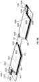
- FIG. 8 D illustrates an exploded view of the electrochromic lenses
- FIG. 8 E shows an exploded view of a polymer type electrochromic lens having a single layer lens
- FIG. 9 illustrates a block diagram of electronic components of the eyewear device.
- FIG. 10 illustrates a method of operating the eyewear.
- This disclosure is directed to eyewear having electrochromic lenses for controlling a light transmissive property/tinting for a user's eye and a camera.
- the electrochromic lenses have an eye region for controlling light transmission to a user's eye, and a separate camera region for controlling light transmission to a camera.
- Two or more electrochromic lenses are provided to independently control the tinting for each of the user's eye, and two or more cameras.
- the electrochromic lenses comprise of multiple layers forming a single stack. Each layer has an opening configured to receive a fill material, such as a dye, such that the fill material can have different chemistries.
- the displays may also have different dye chemistries to allow for different tint ranges (wavelengths of light passed).
- Coupled refers to any logical, optical, physical or electrical connection, link or the like by which signals or light produced or supplied by one system element are imparted to another coupled element. Unless described otherwise, coupled elements or devices are not necessarily directly connected to one another and may be separated by intermediate components, elements or communication media that may modify, manipulate or carry the light or signals.
- the orientations of the eyewear device, associated components and any complete devices incorporating an eye scanner and camera such as shown in any of the drawings, are given by way of example only, for illustration and discussion purposes.
- the eyewear device may be oriented in any other direction suitable to the particular application of the eyewear device, for example up, down, sideways, or any other orientation.
- any directional term such as front, rear, inwards, outwards, towards, left, right, lateral, longitudinal, up, down, upper, lower, top, bottom and side, are used by way of example only, and are not limiting as to direction or orientation of any optic or component of an optic constructed as otherwise described herein.
- FIG. 1 A is a side view of an example hardware configuration of an eyewear device 100 , which includes a right optical assembly 180 B with an image display 180 D ( FIG. 2 A ).
- Eyewear device 100 includes multiple visible light cameras 114 A-B ( FIG. 7 ) that form a stereo camera, of which the right visible light camera 114 B is located on a right temple 110 B.
- the left and right visible light cameras 114 A-B have an image sensor that is sensitive to the visible light range wavelength.
- Each of the visible light cameras 114 A-B have a different frontward facing angle of coverage, for example, visible light camera 114 B has the depicted angle of coverage 111 B.
- the angle of coverage is an angle range which the image sensor of the visible light camera 114 A-B picks up electromagnetic radiation and generates images.
- Examples of such visible lights camera 114 A-B include a high-resolution complementary metal-oxide-semiconductor (CMOS) image sensor and a video graphic array (VGA) camera, such as 640p (e.g., 640 ⁇ 480 pixels for a total of 0.3 megapixels), 720p, or 1080p.
- CMOS complementary metal-oxide-semiconductor
- VGA video graphic array
- Image sensor data from the visible light cameras 114 A-B are captured along with geolocation data, digitized by an image processor, and stored in a memory.
- visible light cameras 114 A-B may be coupled to an image processor (element 912 of FIG. 9 ) for digital processing along with a timestamp in which the image of the scene is captured.
- Image processor 912 includes circuitry to receive signals from the visible light camera 114 A-B and process those signals from the visible light cameras 114 A-B into a format suitable for storage in the memory (element 934 of FIG. 9 ).
- the timestamp can be added by the image processor 912 or other processor, which controls operation of the visible light cameras 114 A-B.
- Visible light cameras 114 A-B allow the stereo camera to simulate human binocular vision. Stereo cameras provide the ability to reproduce three-dimensional images (element 715 of FIG.
- Such three-dimensional images 715 allow for an immersive life-like experience, e.g., for virtual reality or video gaming.
- the pair of images 758 A-B are generated at a given moment in time—one image for each of the left and right visible light cameras 114 A-B.
- the pair of generated images 758 A-B from the frontward facing field of view (FOV) 111 A-B of the left and right visible light cameras 114 A-B are stitched together (e.g., by the image processor 912 ), depth perception is provided by the optical assembly 180 A-B.
- FOV frontward facing field of view
- a user interface field of view adjustment system includes the eyewear device 100 .
- the eyewear device 100 includes a frame 105 , a right temple 110 B extending from a right lateral side 170 B of the frame 105 , and a see-through image display 180 D ( FIGS. 2 A-B ) comprising optical assembly 180 B to present a graphical user interface to a user.
- the eyewear device 100 includes the left visible light camera 114 A connected to the frame 105 or the left temple 110 A to capture a first image of the scene.
- Eyewear device 100 further includes the right visible light camera 114 B connected to the frame 105 or the right temple 110 B to capture (e.g., simultaneously with the left visible light camera 114 A) a second image of the scene which partially overlaps the first image.
- the user interface field of view adjustment system further includes the processor 932 coupled to the eyewear device 100 and connected to the visible light cameras 114 A-B, the memory 934 accessible to the processor 932 , and programming in the memory 934 , for example in the eyewear device 100 itself or another part of the user interface field of view adjustment system.
- the eyewear device 100 also includes a head movement tracker (element 109 of FIG. 1 B ) or an eye movement tracker (element 213 of FIGS. 2 A-B ).
- Eyewear device 100 further includes the see-through image displays 180 C-D of optical assembly 180 A-B, respectfully, for presenting a sequence of displayed images, and an image display driver (element 942 of FIG. 9 ) coupled to the see-through image displays 180 C-D of optical assembly 180 A-B to control the image displays 180 C-D of optical assembly 180 A-B to present the sequence of displayed images 715 , which are described in further detail below.
- Eyewear device 100 further includes the memory 934 and the processor 932 having access to the image display driver 942 and the memory 934 .
- Eyewear device 100 further includes programming (element 934 of FIG. 9 ) in the memory. Execution of the programming by the processor 932 configures the eyewear device 100 to perform functions, including functions to present, via the see-through image displays 180 C-D, an initial displayed image of the sequence of displayed images, the initial displayed image having an initial field of view corresponding to an initial head direction or an initial eye gaze direction (element 230 of FIG. 5 ).
- Execution of the programming by the processor 932 further configures the eyewear device 100 to detect movement of a user of the eyewear device by: (i) tracking, via the head movement tracker (element 109 of FIG. 1 B ), a head movement of a head of the user, or (ii) tracking, via an eye movement tracker (element 113 , 213 of FIGS. 2 A-B , FIG. 5 ), an eye movement of an eye of the user of the eyewear device 100 .
- Execution of the programming by the processor 932 further configures the eyewear device 100 to determine a field of view adjustment to the initial field of view of the initial displayed image based on the detected movement of the user.
- the field of view adjustment includes a successive field of view corresponding to a successive head direction or a successive eye direction.
- Execution of the programming by the processor 932 further configures the eyewear device 100 to generate a successive displayed image of the sequence of displayed images based on the field of view adjustment.
- Execution of the programming by the processor 932 further configures the eyewear device 100 to present, via the see-through image displays 180 C-D of the optical assembly 180 A-B, the successive displayed images.
- FIG. 1 B is a top cross-sectional view of the temple of the eyewear device 100 of FIG. 1 A depicting the right visible light camera 114 B, a head movement tracker 109 , and a circuit board. Construction and placement of the left visible light camera 114 A is substantially similar to the right visible light camera 114 B, except the connections and coupling are on the left lateral side 170 A.
- the eyewear device 100 includes the right visible light camera 114 B and a circuit board, which may be a flexible printed circuit board (PCB) 140 .
- the right hinge 126 B connects the right temple 110 B to a right temple 125 B of the eyewear device 100 .
- components of the right visible light camera 114 B, the flexible PCB 140 , or other electrical connectors or contacts may be located on the right temple 125 B or the right hinge 126 B.
- eyewear device 100 has a head movement tracker 109 , which includes, for example, an inertial measurement unit (IMU).
- IMU inertial measurement unit
- An inertial measurement unit is an electronic device that measures and reports a body's specific force, angular rate, and sometimes the magnetic field surrounding the body, using a combination of accelerometers and gyroscopes, sometimes also magnetometers.
- the inertial measurement unit works by detecting linear acceleration using one or more accelerometers and rotational rate using one or more gyroscopes.
- Typical configurations of inertial measurement units contain one accelerometer, gyro, and magnetometer per axis for each of the three axes: horizontal axis for left-right movement (X), vertical axis (Y) for top-bottom movement, and depth or distance axis for up-down movement (Z).
- the accelerometer detects the gravity vector.
- the magnetometer defines the rotation in the magnetic field (e.g., facing south, north, etc.) like a compass which generates a heading reference.
- the three accelerometers to detect acceleration along the horizontal, vertical, and depth axis defined above, which can be defined relative to the ground, the eyewear device 100 , or the user wearing the eyewear device 100 .
- Eyewear device 100 detects movement of the user of the eyewear device 100 by tracking, via the head movement tracker 109 , the head movement of the head of the user.
- the head movement includes a variation of head direction on a horizontal axis, a vertical axis, or a combination thereof from the initial head direction during presentation of the initial displayed image on the image display.
- tracking, via the head movement tracker 109 , the head movement of the head of the user includes measuring, via the inertial measurement unit 109 , the initial head direction on the horizontal axis (e.g., X axis), the vertical axis (e.g., Y axis), or the combination thereof (e.g., transverse or diagonal movement).
- Tracking, via the head movement tracker 109 , the head movement of the head of the user further includes measuring, via the inertial measurement unit 109 , a successive head direction on the horizontal axis, the vertical axis, or the combination thereof during presentation of the initial displayed image.
- Tracking, via the head movement tracker 109 , the head movement of the head of the user further includes determining the variation of head direction based on both the initial head direction and the successive head direction.
- Detecting movement of the user of the eyewear device 100 further includes in response to tracking, via the head movement tracker 109 , the head movement of the head of the user, determining that the variation of head direction exceeds a deviation angle threshold on the horizontal axis, the vertical axis, or the combination thereof.
- the deviation angle threshold is between about 3° to 10°.
- the term “about” when referring to an angle means ⁇ 10% from the stated amount.
- Variation along the horizontal axis slides three-dimensional objects, such as characters, Bitmojis, application icons, etc. in and out of the field of view by, for example, hiding, unhiding, or otherwise adjusting visibility of the three-dimensional object.
- Variation along the vertical axis for example, when the user looks upwards, in one example, displays weather information, time of day, date, calendar appointments, etc. In another example, when the user looks downwards on the vertical axis, the eyewear device 100 may power down.
- the right temple 110 B includes temple body 211 and a temple cap, with the temple cap omitted in the cross-section of FIG. 1 B .
- various interconnected circuit boards such as PCBs or flexible PCBs, that include controller circuits for right visible light camera 114 B, microphone(s) 130 , speaker(s) 132 , low-power wireless circuitry (e.g., for wireless short-range network communication via BluetoothTM) high-speed wireless circuitry (e.g., for wireless local area network communication via WiFi).
- the right visible light camera 114 B is coupled to or disposed on the flexible PCB 240 and covered by a visible light camera cover lens, which is aimed through opening(s) formed in the right temple 110 B.
- the frame 105 connected to the right temple 110 B includes the opening(s) for the visible light camera cover lens.
- the frame 105 includes a front-facing side configured to face outwards away from the eye of the user.
- the opening for the visible light camera cover lens is formed on and through the front-facing side.
- the right visible light camera 114 B has an outward facing angle of coverage 111 B with a line of sight or perspective of the right eye of the user of the eyewear device 100 .
- the visible light camera cover lens can also be adhered to an outward facing surface of the right temple 110 B in which an opening is formed with an outwards facing angle of coverage, but in a different outwards direction.
- the coupling can also be indirect via intervening components.
- Left (first) visible light camera 114 A is connected to the left see-through image display 180 C of left optical assembly 180 A to generate a first background scene of a first successive displayed image.
- the right (second) visible light camera 114 B is connected to the right see-through image display 180 D of right optical assembly 180 B to generate a second background scene of a second successive displayed image.
- the first background scene and the second background scene partially overlap to present a three-dimensional observable area of the successive displayed image.
- Flexible PCB 140 is disposed inside the right temple 110 B and is coupled to one or more other components housed in the right temple 110 B. Although shown as being formed on the circuit boards of the right temple 110 B, the right visible light camera 114 B can be formed on the circuit boards of the left temple 110 A, the temples 125 A-B, or frame 105 .
- FIG. 2 A is a rear view of an example hardware configuration of an eyewear device 100 , which includes an eye scanner 113 on a frame 105 , for use in a system for determining an eye position and gaze direction of a wearer/user of the eyewear device 100 .
- the eyewear device 100 is in a form configured for wearing by a user, which are eyeglasses in the example of FIG. 2 A .
- the eyewear device 100 can take other forms and may incorporate other types of frameworks, for example, a headgear, a headset, or a helmet.
- eyewear device 100 includes the frame 105 which includes the left rim 107 A connected to the right rim 107 B via the bridge 106 adapted for a nose of the user.
- the left and right rims 107 A-B include respective apertures 175 A-B which hold the respective optical element 180 A-B, such as a lens and the see-through displays 180 C-D.
- the term lens is meant to cover transparent or translucent pieces of glass or plastic having curved and flat surfaces that cause light to converge/diverge or that cause little or no convergence/divergence.
- eyewear device 100 can include other arrangements, such as a single optical element depending on the application or intended user of the eyewear device 100 .
- eyewear device 100 includes the left temple 110 A adjacent the left lateral side 170 A of the frame 105 and the right temple 110 B adjacent the right lateral side 170 B of the frame 105 .
- the temples 110 A-B may be integrated into the frame 105 on the respective sides 170 A-B (as illustrated) or implemented as separate components attached to the frame 105 on the respective sides 170 A-B.
- the temples 110 A-B may be integrated into temples (not shown) attached to the frame 105 .
- the eye scanner 113 includes an infrared emitter 115 and an infrared camera 120 .
- Visible light cameras typically include a blue light filter to block infrared light detection
- the infrared camera 120 is a visible light camera, such as a low-resolution video graphic array (VGA) camera (e.g., 640 ⁇ 480 pixels for a total of 0.3 megapixels), with the blue filter removed.
- VGA video graphic array
- the infrared emitter 115 and the infrared camera 120 are co-located on the frame 105 , for example, both are shown as connected to the upper portion of the left rim 107 A.
- the frame 105 or one or more of the left and right temples 110 A-B include a circuit board (not shown) that includes the infrared emitter 115 and the infrared camera 120 .
- the infrared emitter 115 and the infrared camera 120 can be connected to the circuit board by soldering, for example.
- infrared emitter 115 and infrared camera 120 can be implemented, including arrangements in which the infrared emitter 115 and infrared camera 120 are both on the right rim 107 B, or in different locations on the frame 105 , for example, the infrared emitter 115 is on the left rim 107 A and the infrared camera 120 is on the right rim 107 B. In another example, the infrared emitter 115 is on the frame 105 and the infrared camera 120 is on one of the temples 110 A-B, or vice versa.
- the infrared emitter 115 can be connected essentially anywhere on the frame 105 , left temple 110 A, or right temple 110 B to emit a pattern of infrared light.
- the infrared camera 120 can be connected essentially anywhere on the frame 105 , left temple 110 A, or right temple 110 B to capture at least one reflection variation in the emitted pattern of infrared light.
- the infrared emitter 115 and infrared camera 120 are arranged to face inwards towards an eye of the user with a partial or full field of view of the eye in order to identify the respective eye position and gaze direction.
- the infrared emitter 115 and infrared camera 120 are positioned directly in front of the eye, in the upper part of the frame 105 or in the temples 110 A-B at either ends of the frame 105 .
- FIG. 2 B is a rear view of an example hardware configuration of another eyewear device 200 .
- the eyewear device 200 is depicted as including an eye scanner 213 on a right temple 210 B.
- an infrared emitter 215 and an infrared camera 220 are co-located on the right temple 210 B.
- the eye scanner 213 or one or more components of the eye scanner 213 can be located on the left temple 210 A and other locations of the eyewear device 200 , for example, the frame 105 .
- the infrared emitter 215 and infrared camera 220 are like that of FIG. 2 A , but the eye scanner 213 can be varied to be sensitive to different light wavelengths as described previously in FIG. 2 A .
- the eyewear device 200 includes a frame 105 which includes a left rim 107 A which is connected to a right rim 107 B via a bridge 106 ; and the left and right rims 107 A-B include respective apertures which hold the respective optical elements 180 A-B comprising the see-through display 180 C-D.
- FIGS. 2 C-D are rear views of example hardware configurations of the eyewear device 100 , including two different types of see-through image displays 180 C-D.
- these see-through image displays 180 C-D of optical assembly 180 A-B include an integrated image display.
- the optical assemblies 180 A-B includes a suitable display matrix 180 C-D of any suitable type, such as a liquid crystal display (LCD), an organic light-emitting diode (OLED) display, a waveguide display, or any other such display.
- LCD liquid crystal display
- OLED organic light-emitting diode
- the optical assembly 180 A-B also includes an optical layer or layers 176 , which can include lenses, optical coatings, prisms, mirrors, waveguides, optical strips, and other optical components in any combination.
- the optical layers 176 A-N can include a prism having a suitable size and configuration and including a first surface for receiving light from display matrix and a second surface for emitting light to the eye of the user.
- the prism of the optical layers 176 A-N extends over all or at least a portion of the respective apertures 175 A-B formed in the left and right rims 107 A-B to permit the user to see the second surface of the prism when the eye of the user is viewing through the corresponding left and right rims 107 A-B.
- the first surface of the prism of the optical layers 176 A-N faces upwardly from the frame 105 and the display matrix overlies the prism so that photons and light emitted by the display matrix impinge the first surface.
- the prism is sized and shaped so that the light is refracted within the prism and is directed towards the eye of the user by the second surface of the prism of the optical layers 176 A-N.
- the second surface of the prism of the optical layers 176 A-N can be convex to direct the light towards the center of the eye.
- the prism can optionally be sized and shaped to magnify the image projected by the see-through image displays 180 C-D, and the light travels through the prism so that the image viewed from the second surface is larger in one or more dimensions than the image emitted from the see-through image displays 180 C-D.
- the see-through image displays 180 C-D of optical assembly 180 A-B include a projection image display as shown in FIG. 2 D .
- the optical assembly 180 A-B includes a laser projector 150 , which is a three-color laser projector using a scanning mirror or galvanometer.
- an optical source such as a laser projector 150 is disposed in or on one of the temples 125 A-B of the eyewear device 100 .
- Optical assembly 180 A-B includes one or more optical strips 155 A-N spaced apart across the width of the lens of the optical assembly 180 A-B or across a depth of the lens between the front surface and the rear surface of the lens.
- the photons projected by the laser projector 150 travel across the lens of the optical assembly 180 A-B, the photons encounter the optical strips 155 A-N.
- the photon is either redirected towards the user's eye, or it passes to the next optical strip.
- a combination of modulation of laser projector 150 , and modulation of optical strips may control specific photons or beams of light.
- a processor controls optical strips 155 A-N by initiating mechanical, acoustic, or electromagnetic signals.
- the eyewear device 100 can include other arrangements, such as a single or three optical assemblies, or the optical assembly 180 A-B may have arranged different arrangement depending on the application or intended user of the eyewear device 100 .
- eyewear device 100 includes a left temple 110 A adjacent the left lateral side 170 A of the frame 105 and a right temple 110 B adjacent the right lateral side 170 B of the frame 105 .
- the temples 110 A-B may be integrated into the frame 105 on the respective lateral sides 170 A-B (as illustrated) or implemented as separate components attached to the frame 105 on the respective sides 170 A-B.
- the temples 110 A-B may be integrated into temples 125 A-B attached to the frame 105 .
- the see-through image displays include the first see-through image display 180 C and the second see-through image display 180 D.
- Eyewear device 100 includes first and second apertures 175 A-B which hold the respective first and second optical assembly 180 A-B.
- the first optical assembly 180 A includes the first see-through image display 180 C (e.g., a display matrix of FIG. 2 C or optical strips 155 A-N′ and a projector 150 A).
- the second optical assembly 180 B includes the second see-through image display 180 D e.g., a display matrix of FIG. 2 C or optical strips 155 A-N′′ and a projector 150 B).
- the successive field of view of the successive displayed image includes an angle of view between about 15° to 30, and more specifically 24°, measured horizontally, vertically, or diagonally.
- the successive displayed image having the successive field of view represents a combined three-dimensional observable area visible through stitching together of two displayed images presented on the first and second image displays.
- an angle of view describes the angular extent of the field of view associated with the displayed images presented on each of the left and right image displays 180 C-D of optical assembly 180 A-B.
- the “angle of coverage” describes the angle range that a lens of visible light cameras 114 A-B or infrared camera 220 can image.
- the image circle produced by a lens is large enough to cover the film or sensor completely, possibly including some vignetting (i.e., a reduction of an image's brightness or saturation toward the periphery compared to the image center). If the angle of coverage of the lens does not fill the sensor, the image circle will be visible, typically with strong vignetting toward the edge, and the effective angle of view will be limited to the angle of coverage.
- the “field of view” is intended to describe the field of observable area which the user of the eyewear device 100 can see through his or her eyes via the displayed images presented on the left and right image displays 180 C-D of the optical assembly 180 A-B.
- Image display 180 C of optical assembly 180 A-B can have a field of view with an angle of coverage between 15° to 30°, for example 24°, and have a resolution of 480 ⁇ 480 pixels.
- FIG. 3 shows a rear perspective view of the eyewear device of FIG. 2 A .
- the eyewear device 100 includes an infrared emitter 215 , infrared camera 220 , a frame front 330 , a frame back 335 , and a circuit board 340 . It can be seen in FIG. 3 that the upper portion of the left rim of the frame of the eyewear device 100 includes the frame front 330 and the frame back 335 . An opening for the infrared emitter 215 is formed on the frame back 335 .
- a circuit board which is a flexible PCB 340 , is sandwiched between the frame front 330 and the frame back 335 . Also shown in further detail is the attachment of the left temple 110 A to the left temple 325 A via the left hinge 126 A.
- components of the eye movement tracker 213 including the infrared emitter 215 , the flexible PCB 340 , or other electrical connectors or contacts may be located on the left temple 325 A or the left hinge 126 A.
- FIG. 4 is a cross-sectional view through the infrared emitter 215 and the frame corresponding to the encircled cross-section 4 of the eyewear device of FIG. 3 .
- Multiple layers of the eyewear device 100 are illustrated in the cross-section of FIG. 4 , as shown the frame includes the frame front 330 and the frame back 335 .
- the flexible PCB 340 is disposed on the frame front 330 and connected to the frame back 335 .
- the infrared emitter 215 is disposed on the flexible PCB 340 and covered by an infrared emitter cover lens 445 .
- the infrared emitter 215 is reflowed to the back of the flexible PCB 340 .
- Reflowing attaches the infrared emitter 215 to contact pad(s) formed on the back of the flexible PCB 340 by subjecting the flexible PCB 340 to controlled heat which melts a solder paste to connect the two components.
- reflowing is used to surface mount the infrared emitter 215 on the flexible PCB 340 and electrically connect the two components.
- through-holes can be used to connect leads from the infrared emitter 215 to the flexible PCB 340 via interconnects, for example.
- the frame back 335 includes an infrared emitter opening 450 for the infrared emitter cover lens 445 .
- the infrared emitter opening 450 is formed on a rear-facing side of the frame back 335 that is configured to face inwards towards the eye of the user.
- the flexible PCB 340 can be connected to the frame front 330 via the flexible PCB adhesive 460 .
- the infrared emitter cover lens 445 can be connected to the frame back 335 via infrared emitter cover lens adhesive 455 .
- the coupling can also be indirect via intervening components.
- the processor 932 utilizes eye tracker 213 to determine an eye gaze direction 230 of a wearer's eye 234 as shown in FIG. 5 , and an eye position 236 of the wearer's eye 234 within an eyebox as shown in FIG. 6 .
- the eye tracker 213 is a scanner which uses infrared light illumination (e.g., near-infrared, short-wavelength infrared, mid-wavelength infrared, long-wavelength infrared, or far infrared) to captured image of reflection variations of infrared light from the eye 234 to determine the gaze direction 230 of a pupil 232 of the eye 234 , and also the eye position 236 with respect to the see-through display 180 D.
- infrared light illumination e.g., near-infrared, short-wavelength infrared, mid-wavelength infrared, long-wavelength infrared, or far infrared
- FIG. 7 depicts an example of capturing visible light with cameras 114 A-B. Visible light is captured by the left visible light camera 114 A with a round field of view (FOV). 111 A. A chosen rectangular left raw image 758 A is used for image processing by image processor 912 ( FIG. 9 ). Visible light is captured by the right visible light camera 114 B with a round FOV 111 B. A rectangular right raw image 758 B chosen by the image processor 912 is used for image processing by processor 912 .
- FOV field of view
- a three-dimensional image 715 of a three-dimensional scene is generated by processor 912 and displayed by displays 180 C and 180 D and which is viewable by the user.
- FIG. 8 A illustrates a front view of the frame 105 having a left frame opening 802 A and a right frame opening 802 B that support a powered multiple layer electrochromic lens 804 A and 804 B, respectively.
- the electrochromic lenses 804 A and 804 B receive electricity to activate a transparent electrode in a liquid crystal medium.
- the left electrochromic lens 804 A covers the left optical assembly 180 A and the right electrochromic lens 804 B covers the right optical assembly 180 B.
- Each of the multiple layer electrochromic lenses 804 A and 804 B are configured to be controlled by a processor ( FIG. 9 ).
- Each electrochromic lens 804 A and 804 B has 2 or more integrated electrochromic layers in a single laminated stack, which are activated independently by the processor for use in the eyewear 100 with built-in cameras 114 A and 114 B. Multiple liquid crystal layers are stacked to tune a pass band for certain light wavelengths such as the visible light spectrum, and which could also be in the invisible spectrum. The resulting glass provides controllable levels of light attenuation to make the glass more or less opaque.
- the cameras 114 A and 114 B can be hidden from view by the electrochromic lenses 804 A and 804 B when not recording, and unhidden when recording. This is beneficial to address privacy concerns for people who might be recorded.
- the cameras 114 A and 114 B use the electrochromic lenses 804 A and 804 B as a neutral density filter for creative effects in video or photo capture, and tinting.
- the eye-lens tinting can be adjusted to improve visibility and contrast in bright lighting conditions. Having two or more electrochromic lenses 804 A and 804 B allows opacity to be tuned independently.
- One example use of the electrochromic lenses 804 A and 804 B includes exposing the cameras 114 A and 114 B to record during bright light conditions when the eye-lens is dimmed. Another example use is hiding the cameras 114 A and 114 B for privacy in indoor lighting conditions while the electrochromic lenses 804 A and 804 B are fully transparent to maximize visibility. Having two or more electrochromic lenses 804 A and 804 B allows for different chemistries to be used in each to allow for different light wavelength pass bands or different ranges of light attenuation. The range of bandwidths most beneficial for use with cameras are different than those used for eye lenses or see-through AR displays.
- each electrochromic lens 804 A and 804 B consists of two liquid crystal displays 808 stacked and laminated together by adhesive 809 to form a neutral density filter or a single polymeric display. These displays 808 are then assembled by adhesive 811 to a larger front cover glass or a rigid structure 810 (plastic, metal, or other material) which form the front or back of the frame 105 of the eyewear 100 .
- the structure 810 has the openings 802 A and 802 B receiving the respective electrochromic lens 804 A and 804 B.
- Each electrochromic lens 804 A and 804 B consists of two clear sheets 814 of plastic or glass separated by a thin spacer or gasket 812 which forms an enclosed boundary for liquid crystal dye filled in the displays 808 .
- the fill material is inserted into displays 808 via respective openings 828 and 830 , shown as openings 828 A and 828 B, and openings 830 A and 830 B.
- the displays 808 may also have different dye chemistries to allow for different tint ranges (wavelengths of light passed).
- the spacer or gasket 812 forms two or more isolated boundaries for multiple liquid crystal regions of each electrochromic lens 804 A and 804 B, shown as an eye region 820 and a camera region 822 for each electrochromic lens.
- the tinting of each region 820 and 822 is activated and controlled independently by a processor 932 ( FIG. 9 ) via electrodes 824 and 826 , respectively.
- the respective eye region 820 A and 820 B control the light transmissive property of light to the user's eye
- the respective camera region 822 A and 822 B control the light transmissive property of light to the respective cameras 114 A and 114 B.
- each electrochromic lens share the same lens stack, but each region has a display layer fill material that is separated and may have different chemistry.
- the eye regions 820 A and 820 B can be joined in a single larger region if desired.
- FIG. 8 E shows a polymer type of electrochromic lens having a single layer lens, wherein like numbers refer to like elements. In this example, there is no stacking of displays.
- FIG. 9 depicts a high-level functional block diagram including example electronic components disposed in eyewear 100 and 200 .
- the illustrated electronic components include the processor 932 , the memory 934 , and the see-through image display 180 C and 180 D.
- Memory 934 includes instructions for execution by processor 932 to implement functionality of eyewear 100 / 200 , including instructions for processor 932 to control in the image 715 .
- Processor 932 receives power from battery (not shown) and executes the instructions stored in memory 934 , or integrated with the processor 932 on-chip, to perform functionality of eyewear 100 / 200 , and communicating with external devices via wireless connections.
- a user interface adjustment system 900 includes a wearable device, which is the eyewear device 100 with an eye movement tracker 213 (e.g., shown as infrared emitter 215 and infrared camera 220 in FIG. 2 B ).
- User interface adjustments system 900 also includes a mobile device 990 and a server system 998 connected via various networks.
- Mobile device 990 may be a smartphone, tablet, laptop computer, access point, or any other such device capable of connecting with eyewear device 100 using both a low-power wireless connection 925 and a high-speed wireless connection 937 .
- Mobile device 990 is connected to server system 998 and network 995 .
- the network 995 may include any combination of wired and wireless connections.
- Eyewear device 100 includes at least two visible light cameras 114 A-B (one associated with the left lateral side 170 A and one associated with the right lateral side 170 B). Eyewear device 100 further includes two see-through image displays 180 C-D of the optical assembly 180 A-B (one associated with the left lateral side 170 A and one associated with the right lateral side 170 B). Eyewear device 100 also includes image display driver 942 , image processor 912 , low-power circuitry 920 , and high-speed circuitry 930 . The components shown in FIG. 9 for the eyewear device 100 and 200 are located on one or more circuit boards, for example a PCB or flexible PCB, in the temples.
- Left and right visible light cameras 114 A-B can include digital camera elements such as a complementary metal-oxide-semiconductor (CMOS) image sensor, charge coupled device, a lens, or any other respective visible or light capturing elements that may be used to capture data, including images of scenes with unknown objects.
- CMOS complementary metal-oxide-semiconductor
- Eye movement tracking programming 945 implements the user interface field of view adjustment instructions, including, to cause the eyewear device 100 to track, via the eye movement tracker 213 , the eye movement of the eye of the user of the eyewear device 100 .
- Other implemented instructions cause the eyewear device 100 and 200 to determine the FOV adjustment to the initial FOV 111 A-B based on the detected eye movement of the user corresponding to a successive eye direction.
- Further implemented instructions generate a successive displayed image of the sequence of displayed images based on the field of view adjustment. The successive displayed image is produced as visible output to the user via the user interface. This visible output appears on the see-through image displays 180 C-D of optical assembly 180 A-B, which is driven by image display driver 934 to present the sequence of displayed images, including the initial displayed image with the initial field of view and the successive displayed image with the successive field of view.
- high-speed circuitry 930 includes high-speed processor 932 , memory 934 , and high-speed wireless circuitry 936 .
- the image display driver 942 is coupled to the high-speed circuitry 930 and operated by the high-speed processor 932 in order to drive the left and right image displays 180 C-D of the optical assembly 180 A-B.
- High-speed processor 932 may be any processor capable of managing high-speed communications and operation of any general computing system needed for eyewear device 100 .
- High-speed processor 932 includes processing resources needed for managing high-speed data transfers on high-speed wireless connection 937 to a wireless local area network (WLAN) using high-speed wireless circuitry 936 .
- WLAN wireless local area network
- the high-speed processor 932 executes an operating system such as a LINUX operating system or other such operating system of the eyewear device 100 and the operating system is stored in memory 934 for execution. In addition to any other responsibilities, the high-speed processor 932 executing a software architecture for the eyewear device 100 is used to manage data transfers with high-speed wireless circuitry 936 .
- high-speed wireless circuitry 936 is configured to implement Institute of Electrical and Electronic Engineers (IEEE) 802.11 communication standards, also referred to herein as Wi-Fi. In other examples, other high-speed communications standards may be implemented by high-speed wireless circuitry 936 .
- IEEE Institute of Electrical and Electronic Engineers
- Low-power wireless circuitry 924 and the high-speed wireless circuitry 936 of the eyewear device 100 and 200 can include short range transceivers (BluetoothTM) and wireless wide, local, or wide area network transceivers (e.g., cellular or WiFi).
- Mobile device 990 including the transceivers communicating via the low-power wireless connection 925 and high-speed wireless connection 937 , may be implemented using details of the architecture of the eyewear device 100 , as can other elements of network 995 .
- Memory 934 includes any storage device capable of storing various data and applications, including, among other things, color maps, camera data generated by the left and right visible light cameras 114 A-B and the image processor 912 , as well as images generated for display by the image display driver 942 on the see-through image displays 180 C-D of the optical assembly 180 A-B. While memory 934 is shown as integrated with high-speed circuitry 930 , in other examples, memory 934 may be an independent standalone element of the eyewear device 100 . In certain such examples, electrical routing lines may provide a connection through a chip that includes the high-speed processor 932 from the image processor 912 or low-power processor 922 to the memory 934 . In other examples, the high-speed processor 932 may manage addressing of memory 934 such that the low-power processor 922 will boot the high-speed processor 932 any time that a read or write operation involving memory 934 is needed.
- Server system 998 may be one or more computing devices as part of a service or network computing system, for example, that include a processor, a memory, and network communication interface to communicate over the network 995 with the mobile device 990 and eyewear device 100 / 200 .
- Eyewear device 100 and 200 is connected with a host computer.
- the eyewear device 100 is paired with the mobile device 990 via the high-speed wireless connection 937 or connected to the server system 998 via the network 995 .
- Output components of the eyewear device 100 include visual components, such as the left and right image displays 180 C-D of optical assembly 180 A-B as described in FIGS. 2 C-D (e.g., a display such as a liquid crystal display (LCD), a plasma display panel (PDP), a light emitting diode (LED) display, a projector, or a waveguide).
- the image displays 180 C-D of the optical assembly 180 A-B are driven by the image display driver 942 .
- the output components of the eyewear device 100 further include acoustic components (e.g., speakers), haptic components (e.g., a vibratory motor), other signal generators, and so forth.
- the input components of the eyewear device 100 and 200 , the mobile device 990 , and server system 998 may include alphanumeric input components (e.g., a keyboard, a touch screen configured to receive alphanumeric input, a photo-optical keyboard, or other alphanumeric input components), point-based input components (e.g., a mouse, a touchpad, a trackball, a joystick, a motion sensor, or other pointing instruments), tactile input components (e.g., a physical button, a touch screen that provides location and force of touches or touch gestures, or other tactile input components), audio input components (e.g., a microphone), and the like.
- alphanumeric input components e.g., a keyboard, a touch screen configured to receive alphanumeric input, a photo-optical keyboard, or other alphanumeric input components
- point-based input components e.g., a mouse, a touchpad, a trackball, a joystick, a motion sensor, or other
- Eyewear device 100 may optionally include additional peripheral device elements 919 .
- Such peripheral device elements may include ambient light and spectral sensors, biometric sensors, additional sensors, or display elements integrated with eyewear device 100 .
- peripheral device elements 919 may include any I/O components including output components, motion components, position components, or any other such elements described herein.
- the eyewear device 100 can take other forms and may incorporate other types of frameworks, for example, a headgear, a headset, or a helmet.
- the biometric components of the user interface field of view adjustment 900 include components to detect expressions (e.g., hand expressions, facial expressions, vocal expressions, body gestures, or eye tracking), measure biosignals (e.g., blood pressure, heart rate, body temperature, perspiration, or brain waves), identify a person (e.g., voice identification, retinal identification, facial identification, fingerprint identification, or electroencephalogram based identification), and the like.
- the motion components include acceleration sensor components (e.g., accelerometer), gravitation sensor components, rotation sensor components (e.g., gyroscope), and so forth.
- the position components include location sensor components to generate location coordinates (e.g., a Global Positioning System (GPS) receiver component), WiFi or BluetoothTM transceivers to generate positioning system coordinates, altitude sensor components (e.g., altimeters or barometers that detect air pressure from which altitude may be derived), orientation sensor components (e.g., magnetometers), and the like.
- location sensor components to generate location coordinates
- WiFi or BluetoothTM transceivers to generate positioning system coordinates
- altitude sensor components e.g., altimeters or barometers that detect air pressure from which altitude may be derived
- orientation sensor components e.g., magnetometers
- an “application” or “applications” are program(s) that execute functions defined in the programs.
- Various programming languages can be employed to create one or more of the applications, structured in a variety of manners, such as object-oriented programming languages (e.g., Objective-C, Java, or C++) or procedural programming languages (e.g., C or assembly language).
- a third party application e.g., an application developed using the ANDROIDTM or IOSTM software development kit (SDK) by an entity other than the vendor of the particular platform
- SDK software development kit
- the third-party application can invoke API calls provided by the operating system to facilitate functionality described herein.
- FIG. 10 there is shown a method 1000 for operating the eyewear 100 including the electrochromic lenses 804 A and 804 B.
- the processor 932 determines the light transmissive property/tinting of the left eye region 820 A and the right eye region 820 B of respective electrochromic lenses 804 A and 804 B.
- the processor 932 may determine the light transmissive property/tinting based on the ambient light about the eyewear 100 , or may be user selected such as using a control of the eyewear 100 .
- the displays 808 may also have different dye chemistries to allow for different tint ranges (wavelengths of light passed).
- the processor 932 controls the light transmissive property/tinting of the left eye region 820 A and the right eye region 820 B of respective electrochromic lenses 804 A and 804 B.
- the left eye region 820 A and the right eye region 820 B can be adjusted to improve visibility and contrast in bright lighting conditions. Having two or more electrochromic lenses 804 A and 804 B allows opacity to be tuned independently.
- the processor 932 determines the light transmissive property/tinting of the left camera region 822 A and the right camera region 822 B of respective electrochromic lenses 804 A and 804 B.
- the processor 932 may determine the light transmissive property/tinting based on the ambient light about the eyewear 100 , or may be user selected such as using a control of the eyewear 100 .
- the processor 932 controls the light transmissive property/tinting of the left camera region 822 A and the right camera region 822 B of respective electrochromic lenses 804 A and 804 B.
- the left camera region 822 A and the right camera region 822 B can be adjusted to improve visibility and contrast in bright lighting conditions. Having two or more electrochromic lenses 804 A and 804 B allows opacity to be tuned independently.
- the cameras 114 A and 114 B use the left camera region 822 A and the right camera region 822 B, respectively, as a neutral density filter for creative effects in video or photo capture, and tinting. In the case of the AR eyewear 100 , the tinting can be adjusted to improve visibility and contrast in bright lighting conditions.
- One example use of the electrochromic lenses 804 A and 804 B includes exposing the cameras 114 A and 114 B to record during bright light conditions when the left camera region 822 A and the right camera region 822 B is dimmed. Another example use is hiding the cameras 114 A and 114 B for privacy in indoor lighting conditions while the left camera region 822 A and the right camera region 822 B are fully transparent to maximize visibility.
- electrochromic lenses 804 A and 804 B allows for different chemistries to be used in each to allow for different light wavelength pass bands or different ranges of light attenuation.
- the range of bandwidths most beneficial for use with cameras are different than those used for eye lenses or see-through AR displays.
- any and all measurements, values, ratings, positions, magnitudes, sizes, and other specifications that are set forth in this specification, including in the claims that follow, are approximate, not exact. Such amounts are intended to have a reasonable range that is consistent with the functions to which they relate and with what is customary in the art to which they pertain. For example, unless expressly stated otherwise, a parameter value or the like may vary by as much as ⁇ 10% from the stated amount.
Landscapes
- Physics & Mathematics (AREA)
- Optics & Photonics (AREA)
- General Physics & Mathematics (AREA)
- Health & Medical Sciences (AREA)
- Nonlinear Science (AREA)
- Ophthalmology & Optometry (AREA)
- General Health & Medical Sciences (AREA)
- Mathematical Physics (AREA)
- Chemical & Material Sciences (AREA)
- Crystallography & Structural Chemistry (AREA)
- Otolaryngology (AREA)
- Acoustics & Sound (AREA)
- Eye Examination Apparatus (AREA)
Abstract
Description
Claims (14)
Priority Applications (6)
| Application Number | Priority Date | Filing Date | Title |
|---|---|---|---|
| US17/321,120 US12072566B2 (en) | 2021-05-14 | 2021-05-14 | Eyewear electrochromic lens with multiple tint regions |
| KR1020237042920A KR20240005959A (en) | 2021-05-14 | 2022-05-09 | Eyewear electrochromic lens with multiple tint zones |
| CN202280035075.6A CN117321473A (en) | 2021-05-14 | 2022-05-09 | Goggle electrochromic lenses with multiple tint zones |
| PCT/US2022/028283 WO2022240724A1 (en) | 2021-05-14 | 2022-05-09 | Eyewear electrochromic lens with multiple tint regions |
| EP22726234.2A EP4338002A1 (en) | 2021-05-14 | 2022-05-09 | Eyewear electrochromic lens with multiple tint regions |
| US18/806,293 US20240402529A1 (en) | 2021-05-14 | 2024-08-15 | Eyewear electrochromic lens with multiple tint regions |
Applications Claiming Priority (1)
| Application Number | Priority Date | Filing Date | Title |
|---|---|---|---|
| US17/321,120 US12072566B2 (en) | 2021-05-14 | 2021-05-14 | Eyewear electrochromic lens with multiple tint regions |
Related Child Applications (1)
| Application Number | Title | Priority Date | Filing Date |
|---|---|---|---|
| US18/806,293 Continuation US20240402529A1 (en) | 2021-05-14 | 2024-08-15 | Eyewear electrochromic lens with multiple tint regions |
Publications (2)
| Publication Number | Publication Date |
|---|---|
| US20220365370A1 US20220365370A1 (en) | 2022-11-17 |
| US12072566B2 true US12072566B2 (en) | 2024-08-27 |
Family
ID=81850827
Family Applications (2)
| Application Number | Title | Priority Date | Filing Date |
|---|---|---|---|
| US17/321,120 Active 2042-08-05 US12072566B2 (en) | 2021-05-14 | 2021-05-14 | Eyewear electrochromic lens with multiple tint regions |
| US18/806,293 Pending US20240402529A1 (en) | 2021-05-14 | 2024-08-15 | Eyewear electrochromic lens with multiple tint regions |
Family Applications After (1)
| Application Number | Title | Priority Date | Filing Date |
|---|---|---|---|
| US18/806,293 Pending US20240402529A1 (en) | 2021-05-14 | 2024-08-15 | Eyewear electrochromic lens with multiple tint regions |
Country Status (5)
| Country | Link |
|---|---|
| US (2) | US12072566B2 (en) |
| EP (1) | EP4338002A1 (en) |
| KR (1) | KR20240005959A (en) |
| CN (1) | CN117321473A (en) |
| WO (1) | WO2022240724A1 (en) |
Families Citing this family (2)
| Publication number | Priority date | Publication date | Assignee | Title |
|---|---|---|---|---|
| TW202326231A (en) * | 2021-08-30 | 2023-07-01 | 美商元平台技術有限公司 | Ophthalmic lens with embedded dimmer |
| US12298514B1 (en) * | 2023-04-17 | 2025-05-13 | Snap Inc. | Augmented reality headset with controllably dimmable filter |
Citations (5)
| Publication number | Priority date | Publication date | Assignee | Title |
|---|---|---|---|---|
| US20180246327A1 (en) * | 2017-02-27 | 2018-08-30 | Seiko Epson Corporation | Image display apparatus |
| US20190384062A1 (en) * | 2018-06-19 | 2019-12-19 | Apple Inc. | Electronic Devices Having Electrically Adjustable Optical Layers |
| CN111458876A (en) | 2020-03-30 | 2020-07-28 | Oppo广东移动通信有限公司 | Control method of head-mounted display device and head-mounted display device |
| US20210097749A1 (en) | 2019-09-29 | 2021-04-01 | Sagi Katz | Stylized image painting |
| US20220345599A1 (en) * | 2020-02-06 | 2022-10-27 | Canon Kabushiki Kaisha | Light modulating element and optical apparatus, imaging apparatus and lens unit using the same |
Family Cites Families (1)
| Publication number | Priority date | Publication date | Assignee | Title |
|---|---|---|---|---|
| US20200409182A1 (en) * | 2019-06-28 | 2020-12-31 | Yuuya ENDOH | Optical element and spectacles |
-
2021
- 2021-05-14 US US17/321,120 patent/US12072566B2/en active Active
-
2022
- 2022-05-09 EP EP22726234.2A patent/EP4338002A1/en active Pending
- 2022-05-09 WO PCT/US2022/028283 patent/WO2022240724A1/en not_active Ceased
- 2022-05-09 CN CN202280035075.6A patent/CN117321473A/en active Pending
- 2022-05-09 KR KR1020237042920A patent/KR20240005959A/en active Pending
-
2024
- 2024-08-15 US US18/806,293 patent/US20240402529A1/en active Pending
Patent Citations (5)
| Publication number | Priority date | Publication date | Assignee | Title |
|---|---|---|---|---|
| US20180246327A1 (en) * | 2017-02-27 | 2018-08-30 | Seiko Epson Corporation | Image display apparatus |
| US20190384062A1 (en) * | 2018-06-19 | 2019-12-19 | Apple Inc. | Electronic Devices Having Electrically Adjustable Optical Layers |
| US20210097749A1 (en) | 2019-09-29 | 2021-04-01 | Sagi Katz | Stylized image painting |
| US20220345599A1 (en) * | 2020-02-06 | 2022-10-27 | Canon Kabushiki Kaisha | Light modulating element and optical apparatus, imaging apparatus and lens unit using the same |
| CN111458876A (en) | 2020-03-30 | 2020-07-28 | Oppo广东移动通信有限公司 | Control method of head-mounted display device and head-mounted display device |
Non-Patent Citations (1)
| Title |
|---|
| International Search Report and Written Opinion for International Application No. PCT/US2022/028283, dated Aug. 17, 2022 (Aug. 17, 2022)—10 pages. |
Also Published As
| Publication number | Publication date |
|---|---|
| US20220365370A1 (en) | 2022-11-17 |
| US20240402529A1 (en) | 2024-12-05 |
| EP4338002A1 (en) | 2024-03-20 |
| KR20240005959A (en) | 2024-01-12 |
| WO2022240724A1 (en) | 2022-11-17 |
| CN117321473A (en) | 2023-12-29 |
Similar Documents
| Publication | Publication Date | Title |
|---|---|---|
| US12372807B2 (en) | Hyperextending hinge for wearable electronic device | |
| US12231761B2 (en) | Eyewear determining facial expressions using muscle sensors | |
| US12259595B2 (en) | Hyperextending hinge having FPC service loops for eyewear | |
| US11575877B2 (en) | Utilizing dual cameras for continuous camera capture | |
| US12111515B2 (en) | Hyperextending hinge having cosmetic trim for eyewear | |
| US11899283B2 (en) | Antenna implementation embedded in optical waveguide module | |
| US20240402529A1 (en) | Eyewear electrochromic lens with multiple tint regions | |
| US20230204958A1 (en) | Eyewear electronic tinting lens with integrated waveguide | |
| US11619819B2 (en) | Eyewear display for generating an immersive image | |
| US11506902B2 (en) | Digital glasses having display vision enhancement | |
| US12241755B2 (en) | Navigation assistance for the visually impaired | |
| US11880039B2 (en) | Polarized reflective pinhole mirror display | |
| US20230185090A1 (en) | Eyewear including a non-uniform push-pull lens set | |
| US20260006171A1 (en) | Dynamic display color adjustment by eye tracking | |
| WO2023129289A1 (en) | Eyewear electronic tinting lens with integrated waveguide |
Legal Events
| Date | Code | Title | Description |
|---|---|---|---|
| FEPP | Fee payment procedure |
Free format text: ENTITY STATUS SET TO UNDISCOUNTED (ORIGINAL EVENT CODE: BIG.); ENTITY STATUS OF PATENT OWNER: LARGE ENTITY |
|
| STPP | Information on status: patent application and granting procedure in general |
Free format text: DOCKETED NEW CASE - READY FOR EXAMINATION |
|
| STPP | Information on status: patent application and granting procedure in general |
Free format text: NON FINAL ACTION MAILED |
|
| STPP | Information on status: patent application and granting procedure in general |
Free format text: RESPONSE TO NON-FINAL OFFICE ACTION ENTERED AND FORWARDED TO EXAMINER |
|
| STPP | Information on status: patent application and granting procedure in general |
Free format text: FINAL REJECTION MAILED |
|
| STPP | Information on status: patent application and granting procedure in general |
Free format text: ADVISORY ACTION MAILED |
|
| STPP | Information on status: patent application and granting procedure in general |
Free format text: DOCKETED NEW CASE - READY FOR EXAMINATION |
|
| STPP | Information on status: patent application and granting procedure in general |
Free format text: NOTICE OF ALLOWANCE MAILED -- APPLICATION RECEIVED IN OFFICE OF PUBLICATIONS |
|
| ZAAA | Notice of allowance and fees due |
Free format text: ORIGINAL CODE: NOA |
|
| ZAAB | Notice of allowance mailed |
Free format text: ORIGINAL CODE: MN/=. |
|
| STPP | Information on status: patent application and granting procedure in general |
Free format text: NOTICE OF ALLOWANCE MAILED -- APPLICATION RECEIVED IN OFFICE OF PUBLICATIONS |
|
| ZAAA | Notice of allowance and fees due |
Free format text: ORIGINAL CODE: NOA |
|
| AS | Assignment |
Owner name: SNAP INC., CALIFORNIA Free format text: ASSIGNMENT OF ASSIGNORS INTEREST;ASSIGNORS:SINGH, AMIT;STEGER, STEPHEN ANDREW;THOMPSON, SAMUEL BRYSON;REEL/FRAME:068009/0395 Effective date: 20210514 Owner name: SNAP INC., CALIFORNIA Free format text: ASSIGNMENT OF ASSIGNOR'S INTEREST;ASSIGNORS:SINGH, AMIT;STEGER, STEPHEN ANDREW;THOMPSON, SAMUEL BRYSON;REEL/FRAME:068009/0395 Effective date: 20210514 |
|
| STPP | Information on status: patent application and granting procedure in general |
Free format text: PUBLICATIONS -- ISSUE FEE PAYMENT VERIFIED |
|
| STCF | Information on status: patent grant |
Free format text: PATENTED CASE |