US12072482B2 - Telescope with stiffening rib - Google Patents
Telescope with stiffening rib Download PDFInfo
- Publication number
- US12072482B2 US12072482B2 US18/157,625 US202318157625A US12072482B2 US 12072482 B2 US12072482 B2 US 12072482B2 US 202318157625 A US202318157625 A US 202318157625A US 12072482 B2 US12072482 B2 US 12072482B2
- Authority
- US
- United States
- Prior art keywords
- housing
- radiation
- outlet
- strut assembly
- partial
- Prior art date
- Legal status (The legal status is an assumption and is not a legal conclusion. Google has not performed a legal analysis and makes no representation as to the accuracy of the status listed.)
- Active, expires
Links
- 230000005855 radiation Effects 0.000 claims abstract description 47
- 230000003287 optical effect Effects 0.000 claims abstract description 17
- 230000005670 electromagnetic radiation Effects 0.000 description 9
- 230000008901 benefit Effects 0.000 description 3
- 238000000034 method Methods 0.000 description 3
- 230000000694 effects Effects 0.000 description 2
- 239000000463 material Substances 0.000 description 2
- 238000012986 modification Methods 0.000 description 2
- 230000004048 modification Effects 0.000 description 2
- 230000008569 process Effects 0.000 description 2
- 230000005540 biological transmission Effects 0.000 description 1
- 238000000151 deposition Methods 0.000 description 1
- 230000007613 environmental effect Effects 0.000 description 1
- 238000003384 imaging method Methods 0.000 description 1
- 230000000116 mitigating effect Effects 0.000 description 1
- 239000004570 mortar (masonry) Substances 0.000 description 1
- 238000007493 shaping process Methods 0.000 description 1
- 230000008685 targeting Effects 0.000 description 1
Images


Classifications
-
- G—PHYSICS
- G02—OPTICS
- G02B—OPTICAL ELEMENTS, SYSTEMS OR APPARATUS
- G02B7/00—Mountings, adjusting means, or light-tight connections, for optical elements
- G02B7/18—Mountings, adjusting means, or light-tight connections, for optical elements for prisms; for mirrors
- G02B7/182—Mountings, adjusting means, or light-tight connections, for optical elements for prisms; for mirrors for mirrors
-
- G—PHYSICS
- G02—OPTICS
- G02B—OPTICAL ELEMENTS, SYSTEMS OR APPARATUS
- G02B23/00—Telescopes, e.g. binoculars; Periscopes; Instruments for viewing the inside of hollow bodies; Viewfinders; Optical aiming or sighting devices
- G02B23/02—Telescopes, e.g. binoculars; Periscopes; Instruments for viewing the inside of hollow bodies; Viewfinders; Optical aiming or sighting devices involving prisms or mirrors
- G02B23/10—Telescopes, e.g. binoculars; Periscopes; Instruments for viewing the inside of hollow bodies; Viewfinders; Optical aiming or sighting devices involving prisms or mirrors reflecting into the field of view additional indications, e.g. from collimator
- G02B23/105—Sighting devices with light source and collimating reflector
-
- F—MECHANICAL ENGINEERING; LIGHTING; HEATING; WEAPONS; BLASTING
- F41—WEAPONS
- F41H—ARMOUR; ARMOURED TURRETS; ARMOURED OR ARMED VEHICLES; MEANS OF ATTACK OR DEFENCE, e.g. CAMOUFLAGE, IN GENERAL
- F41H13/00—Means of attack or defence not otherwise provided for
- F41H13/0043—Directed energy weapons, i.e. devices that direct a beam of high energy content toward a target for incapacitating or destroying the target
- F41H13/005—Directed energy weapons, i.e. devices that direct a beam of high energy content toward a target for incapacitating or destroying the target the high-energy beam being a laser beam
-
- G—PHYSICS
- G02—OPTICS
- G02B—OPTICAL ELEMENTS, SYSTEMS OR APPARATUS
- G02B23/00—Telescopes, e.g. binoculars; Periscopes; Instruments for viewing the inside of hollow bodies; Viewfinders; Optical aiming or sighting devices
- G02B23/16—Housings; Caps; Mountings; Supports, e.g. with counterweight
-
- G—PHYSICS
- G02—OPTICS
- G02B—OPTICAL ELEMENTS, SYSTEMS OR APPARATUS
- G02B23/00—Telescopes, e.g. binoculars; Periscopes; Instruments for viewing the inside of hollow bodies; Viewfinders; Optical aiming or sighting devices
- G02B23/02—Telescopes, e.g. binoculars; Periscopes; Instruments for viewing the inside of hollow bodies; Viewfinders; Optical aiming or sighting devices involving prisms or mirrors
Definitions
- the present disclosure relates to optical telescopes and optical trains and, in particular, to a telescope with an improved stiffening rib design.
- the telescope and optical trains are well suited for use in directed energy applications.
- Directed energy weapons directed energy applications (including, but not limited to, applications such as power-beaming), directed energy optical trains (including, but not limited to, application telescopes and expansion optics), and/or directed energy telescopes and, specifically, HEL weapons or optical trains are being considered for a variety of military applications with respect to a variety of platforms. These platforms include, but are not limited to, spaceborne, airborne and land-based systems.
- the weapons or telescopes generally involve the use of a laser or other source of a high-power beam of electromagnetic radiation to track, deposit energy in a controlled manner, and, in some cases, destroy an intended target.
- directed energy weapons or telescopes must accurately track the intended target and maintain a HEL beam on the target until an intended outcome is achieved.
- a directed energy (DE) system e.g., a high-energy (HE) laser system
- HE high-energy
- EM electromagnetic
- stiffening strut assembly installed at an outlet of the housing and through which the emitted EM radiation passes.
- the housing includes a single open end and defines a first opening through which the EM radiation passes and a mirror disposed to reflect the EM radiation toward the single open end.
- the HE laser further includes a specular window and/or opening disposed in the single open end in a path of the EM radiation.
- the stiffening strut assembly includes horizontal baffles supported at opposite ends thereof by the housing at the outlet of the housing.
- the stiffening strut assembly includes a partial or complete annular central member and multiple struts disposed to support the partial or complete annular central member in the outlet of the housing and supported at respective distal ends thereof by the housing at the outlet of the housing.
- the partial or complete annular central member is circular.
- the stiffening strut assembly includes a partial or complete polygonal central member and multiple struts disposed to support the partial or complete polygonal central member in the outlet of the housing and supported at respective distal ends thereof by the housing at the outlet of the housing.
- the partial or complete polygonal central member is rectangular.
- the stiffening strut assembly includes reflective caps configured to reflect the EM radiation.
- the housing is an optically black barrel and the stiffening strut assembly includes thermally isolated optical black struts.
- a high-energy (HE) laser system includes a housing defining an unobscured aperture for emitted electromagnetic (EM) radiation, the housing including a single open end and defining a first opening through which the EM radiation passes, a mirror disposed to reflect the EM radiation incident from the first opening and toward the single open end and a stiffening strut assembly installed at an outlet of the housing opposite the mirror and through which the emitted EM radiation passes.
- EM electromagnetic
- the HE laser system further includes a specular window and/or opening disposed in the single open end in a path of the EM radiation.
- the stiffening strut assembly includes horizontal baffles supported at opposite ends thereof by the housing at the outlet of the housing.
- the stiffening strut assembly includes a partial or complete annular central member and multiple struts disposed to support the partial or complete annular central member in the outlet of the housing and supported at respective distal ends thereof by the housing at the outlet of the housing.
- the partial or complete annular central member is circular.
- the stiffening strut assembly includes a partial or complete polygonal central member and multiple struts disposed to support the partial or complete polygonal central member in the outlet of the housing and supported at respective distal ends thereof by the housing at the outlet of the housing.
- the partial or complete polygonal central member is rectangular.
- the stiffening strut assembly includes reflective caps.
- the barrel is an optical black barrel and the stiffening strut assembly includes thermally isolated optical black struts.
- a directed energy (DE) system includes a housing defining an unobscured aperture for emitted electromagnetic (EM) radiation, the housing including a barrel having a single open end and defining a first opening through which the EM radiation passes and a mirror disposed in the barrel to reflect the EM radiation incident from the first opening and toward the single open end and a stiffening strut assembly installed at an outlet of the housing opposite the mirror and through which the emitted EM radiation passes.
- EM electromagnetic
- FIG. 1 is a perspective view of a weapons system in accordance with embodiments
- FIG. 2 is a side view of a high-energy (HE) laser for use in the weapons system of FIG. 1 in accordance with embodiments;
- HE high-energy
- FIG. 3 is a front view of the high-energy laser of FIG. 2 in accordance with embodiments
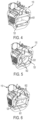
- FIG. 4 is a perspective view of a housing of the high-energy laser of FIGS. 2 and 3 A in accordance with embodiments;
- FIG. 5 is a perspective view of a housing of the high-energy laser of FIGS. 2 and 3 A in accordance with embodiments.
- FIG. 6 is a perspective view of a housing of the high-energy laser of FIGS. 2 and 3 A in accordance with embodiments.
- a beam director subsystem often includes a source of electromagnetic radiation for generating, shaping, and/or controlling a high-energy (HE) laser beam and a tracking sensor suite with appropriate telescope.
- the electromagnetic radiation is directed to a secondary mirror or set of mirrors that reflects the electromagnetic radiation to a primary mirror for output of the HE laser beam.
- the tracking telescope is coupled to a housing and has a tracking detector configured to receive electromagnetic radiation originating from the HE laser and/or target. In certain embodiments, the tracking telescope is common aperture with the HE laser telescope.
- the beam director subsystem can further include an illuminator for targeting an airborne target and for generating electromagnetic radiation to be directed at the airborne target.
- the tracking detector can receive electromagnetic radiation reflected from the airborne target.
- a processor is typically coupled to the tracking detector and generates a control signal for input to a steering controller to steer the HE laser based at least in part on the received electromagnetic radiation from the airborne target.
- the processor processes target information for tracking the airborne target based at least in part on the received electromagnetic radiation.
- unobscured apertures for HE laser telescopes perform better than those with obscurations.
- unobscured apertures tend to experience “fishmouth” structural modes due to various factors that degrade performance, specifically in high environmental loading situations. These “fishmouth” structural modes manifest as lateral and vertical deformations of telescope housings.
- a HE laser telescope is provided with a stiffening rib design that improves system jitter performance by eliminating and/or mitigating the “fishmouth” structural modes.
- the HE laser telescope has an unobscured aperture with a managed, minor telescope obscuration (a configured stiffening strut/baffle) to improve system jitter in high vibration environments without sacrificing HE laser performance on the target.
- the HE laser telescope can further include improved thermal management of HE laser derived sources from short wave infrared (SWIR) and/or medium wave infrared (MWIR) viewing, thus reducing SWIR and/or MWIR tracking and imaging blinding in a common path HE laser transmission/image receiving aperture as well as provisions for a jitter observer system to further reduce jitter without affecting HE laser operations.
- SWIR short wave infrared
- MWIR medium wave infrared
- a HE laser weapon system 10 includes a beam director subsystem 12 , a radar 14 that detects objects (e.g., mortar shells, unmanned aerial vehicles (UAVs), etc.) in a field (F) and a base 16 that may be secured to a stationary (e.g., a fixed location on a military base) and/or a moving platform (e.g., a tank, ship, etc.) to secure the weapon system.
- the beam director subsystem 12 outputs a HE laser beam for use in depositing energy on the intended target, incapacitating an intended target, and/or otherwise destroying an intended target.
- the beam director subsystem 12 includes a HE laser beam system and a tracking system.
- the HE laser beam director subsystem 12 provides the guidance and control of the HE laser for the weapon system.
- the beam director subsystem 12 includes a source of electromagnetic (EM) radiation for generating the HE laser HEL beam.
- the primary mirror receives EM radiation after an optical train ( FIG. 2 , 115 ) and reflects the EM radiation for output of the HE laser beam through a housing.
- the beam director subsystem 12 further may include a tracking telescope 28 .
- the tracking telescope 28 has a track detector configured to receive a first portion and a second portion of the EM radiation of the HE laser beam.
- the tracking telescope 28 and the track detector are also configured to receive EM emitted by an illuminator and reflected off an intended target.
- a processor is coupled to the tracking detector and a steering controller to control the HE laser beam.
- the processor processes the first and second portions of the HE laser beam along with the EM radiation reflected from the intended target to steer the HE laser at the intended target.
- the HE laser beam may be any type of high energy laser that is capable of radiating EM radiation in a form to destroy and/or disable one or more intended airborne targets.
- the beam director subsystem 12 , HE laser output telescope and some or all of the features of the tracking telescope 28 may be the same telescope, which can be referred to as a common aperture HE laser and track.
- a HE laser 101 is provided for use in a directed energy (DE) system, such as the beam director subsystem 12 of FIG. 1 .
- the HE laser 101 of the DE system includes a housing 110 , a stiffening strut assembly 120 and a specular window 130 and/or opening (hereinafter referred to as a “specular window”).
- the housing 110 is formed to define an unobscured aperture 111 for emitted EM radiation and includes a barrel 112 and a mirror 113 .
- the barrel 112 has a single open end 114 and is formed to define a first opening 115 through which the EM radiation passes as it propagates toward the mirror 113 .
- the mirror 113 is disposed in the barrel 112 and is configured to reflect the EM radiation incident on the mirror 113 from the first opening 115 and toward the single open end 114 .
- the stiffening strut assembly 120 is installed in the housing 110 at an outlet 121 of the housing 110 (i.e., the single open end 114 ) opposite the mirror 113 and is disposed and configured in the single open end 114 to permit the emitted EM radiation to pass through.
- the specular window 130 is disposed in the single open end 114 in a path of the EM radiation and may reflect a portion of the EM radiation away from the single open end 114 .
- the stiffening strut assembly 120 can include reflective caps 122 that are disposed and configured to reflect the EM radiation, which is incident on the reflective caps 122 , outwardly toward an interior surface of the barrel 112 and/or other energy and/or optical dumps 1101 .
- the barrel 112 can be provided as an optical black barrel and the stiffening strut assembly 120 can include struts (to be described in greater detail below) that are provided as thermally isolated and/or optically black struts.
- the stiffening strut assembly 120 obscures a surface area of the mirror 113 and thus obscures a portion of the EM radiation emitted from the housing 110 .
- an incidence of “fishmouth” structural modes of the housing 110 is mitigated, eliminated, and/or at least substantially reduced.
- a beam formed by the EM radiation emitted from the housing 110 has characteristic properties (i.e., focus performance and power-deposited-in-a-bucket) that are preserved over long distances (i.e., 3 km).
- the stiffening strut assembly 120 can include horizontal baffles 401 .
- the horizontal baffles 401 do not obscure the EM emitted from the HE laser 101 to a significant degree as explained above and are supported at opposite ends thereof by the housing 110 at the outlet 121 of the housing 110 or the single open end 114 .
- the stiffening strut assembly 120 includes a partial or complete annular central member 501 and multiple struts 502 .
- the partial or complete annular central member 501 can be provided as a circular feature and/or partially circular feature and does not obscure the EM emitted from the HE laser 101 to a significant degree as explained above.
- the multiple struts 502 can be provided as thermally isolated optical black struts and are disposed to support the partial or complete annular central member 501 in the outlet 121 of the housing 110 or the single open end 114 .
- the multiple struts 502 are supported at respective distal ends thereof by the housing 110 at the outlet 121 of the housing 110 or the single open end 114 .
- the stiffening strut assembly 120 includes a partial or complete polygonal central member 601 and multiple struts 602 .
- the partial or complete polygonal central member 601 can be provided as a rectangular feature and/or any complete or partial polygon and does not obscure the EM emitted from the HE laser 101 to a significant degree as explained above.
- the multiple struts 602 can be provided as thermally isolated optical black struts and are disposed to support the partial or complete polygonal central member 601 in the outlet 121 of the housing 110 or the single open end 114 .
- the multiple struts 602 are supported at respective distal ends thereof by the housing 110 at the outlet 121 of the housing 110 or the single open end 114 .
- a telescope for DE applications e.g., a HE laser telescope
- a stiffening rib design that improves system jitter performance by eliminating the “fishmouth” structural modes.
- the HE laser telescope has an unobscured aperture with a managed, minor telescope obscuration (a configured stiffening strut/baffle) to improve system jitter in high vibration environments without sacrificing power.
Landscapes
- Physics & Mathematics (AREA)
- Optics & Photonics (AREA)
- General Physics & Mathematics (AREA)
- Astronomy & Astrophysics (AREA)
- Engineering & Computer Science (AREA)
- Radar, Positioning & Navigation (AREA)
- Remote Sensing (AREA)
- General Engineering & Computer Science (AREA)
- Lasers (AREA)
- Telescopes (AREA)
Abstract
A directed energy system is provided and includes a housing defining an unobscured aperture for emitted electromagnetic (EM) radiation and a stiffening strut assembly installed at an outlet of the housing and through which the emitted EM radiation passes. The directed energy system and various elements such as the telescope and optical trains described herein are well suited for, but not limited to, high-energy (HE) laser applications.
Description
The present disclosure relates to optical telescopes and optical trains and, in particular, to a telescope with an improved stiffening rib design. The telescope and optical trains are well suited for use in directed energy applications.
Directed energy weapons, directed energy applications (including, but not limited to, applications such as power-beaming), directed energy optical trains (including, but not limited to, application telescopes and expansion optics), and/or directed energy telescopes and, specifically, HEL weapons or optical trains are being considered for a variety of military applications with respect to a variety of platforms. These platforms include, but are not limited to, spaceborne, airborne and land-based systems. The weapons or telescopes generally involve the use of a laser or other source of a high-power beam of electromagnetic radiation to track, deposit energy in a controlled manner, and, in some cases, destroy an intended target. To achieve mission objectives, directed energy weapons or telescopes must accurately track the intended target and maintain a HEL beam on the target until an intended outcome is achieved.
According to an aspect of the disclosure, a directed energy (DE) system, e.g., a high-energy (HE) laser system, is provided and includes a housing defining an unobscured aperture for emitted electromagnetic (EM) radiation and a stiffening strut assembly installed at an outlet of the housing and through which the emitted EM radiation passes.
In accordance with one or more embodiments, the housing includes a single open end and defines a first opening through which the EM radiation passes and a mirror disposed to reflect the EM radiation toward the single open end.
In accordance with one or more embodiments, the HE laser further includes a specular window and/or opening disposed in the single open end in a path of the EM radiation.
In accordance with one or more embodiments, the stiffening strut assembly includes horizontal baffles supported at opposite ends thereof by the housing at the outlet of the housing.
In accordance with one or more embodiments, the stiffening strut assembly includes a partial or complete annular central member and multiple struts disposed to support the partial or complete annular central member in the outlet of the housing and supported at respective distal ends thereof by the housing at the outlet of the housing.
In accordance with one or more embodiments, the partial or complete annular central member is circular.
In accordance with one or more embodiments, the stiffening strut assembly includes a partial or complete polygonal central member and multiple struts disposed to support the partial or complete polygonal central member in the outlet of the housing and supported at respective distal ends thereof by the housing at the outlet of the housing.
In accordance with one or more embodiments, the partial or complete polygonal central member is rectangular.
In accordance with one or more embodiments, the stiffening strut assembly includes reflective caps configured to reflect the EM radiation.
In accordance with one or more embodiments, the housing is an optically black barrel and the stiffening strut assembly includes thermally isolated optical black struts.
According to an aspect of the disclosure, a high-energy (HE) laser system is provided and includes a housing defining an unobscured aperture for emitted electromagnetic (EM) radiation, the housing including a single open end and defining a first opening through which the EM radiation passes, a mirror disposed to reflect the EM radiation incident from the first opening and toward the single open end and a stiffening strut assembly installed at an outlet of the housing opposite the mirror and through which the emitted EM radiation passes.
In accordance with one or more embodiments, the HE laser system further includes a specular window and/or opening disposed in the single open end in a path of the EM radiation.
In accordance with one or more embodiments, the stiffening strut assembly includes horizontal baffles supported at opposite ends thereof by the housing at the outlet of the housing.
In accordance with one or more embodiments, the stiffening strut assembly includes a partial or complete annular central member and multiple struts disposed to support the partial or complete annular central member in the outlet of the housing and supported at respective distal ends thereof by the housing at the outlet of the housing.
In accordance with one or more embodiments, the partial or complete annular central member is circular.
In accordance with one or more embodiments, the stiffening strut assembly includes a partial or complete polygonal central member and multiple struts disposed to support the partial or complete polygonal central member in the outlet of the housing and supported at respective distal ends thereof by the housing at the outlet of the housing.
In accordance with one or more embodiments, the partial or complete polygonal central member is rectangular.
In accordance with one or more embodiments, the stiffening strut assembly includes reflective caps.
In accordance with one or more embodiments, the barrel is an optical black barrel and the stiffening strut assembly includes thermally isolated optical black struts.
According to an aspect of the disclosure, a directed energy (DE) system is provided and includes a housing defining an unobscured aperture for emitted electromagnetic (EM) radiation, the housing including a barrel having a single open end and defining a first opening through which the EM radiation passes and a mirror disposed in the barrel to reflect the EM radiation incident from the first opening and toward the single open end and a stiffening strut assembly installed at an outlet of the housing opposite the mirror and through which the emitted EM radiation passes.
Additional features and advantages are realized through the techniques of the present disclosure. Other embodiments and aspects of the disclosure are described in detail herein and are considered a part of the claimed technical concept. For a better understanding of the disclosure with the advantages and the features, refer to the description and to the drawings.
For a more complete understanding of this disclosure, reference is now made to the following brief description, taken in connection with the accompanying drawings and detailed description, wherein like reference numerals represent like parts:
A beam director subsystem often includes a source of electromagnetic radiation for generating, shaping, and/or controlling a high-energy (HE) laser beam and a tracking sensor suite with appropriate telescope. The electromagnetic radiation is directed to a secondary mirror or set of mirrors that reflects the electromagnetic radiation to a primary mirror for output of the HE laser beam. The tracking telescope is coupled to a housing and has a tracking detector configured to receive electromagnetic radiation originating from the HE laser and/or target. In certain embodiments, the tracking telescope is common aperture with the HE laser telescope. The beam director subsystem can further include an illuminator for targeting an airborne target and for generating electromagnetic radiation to be directed at the airborne target. The tracking detector can receive electromagnetic radiation reflected from the airborne target. A processor is typically coupled to the tracking detector and generates a control signal for input to a steering controller to steer the HE laser based at least in part on the received electromagnetic radiation from the airborne target. The processor processes target information for tracking the airborne target based at least in part on the received electromagnetic radiation.
In certain cases, unobscured apertures for HE laser telescopes perform better than those with obscurations. However, unobscured apertures tend to experience “fishmouth” structural modes due to various factors that degrade performance, specifically in high environmental loading situations. These “fishmouth” structural modes manifest as lateral and vertical deformations of telescope housings.
As will be described below, a HE laser telescope is provided with a stiffening rib design that improves system jitter performance by eliminating and/or mitigating the “fishmouth” structural modes. The HE laser telescope has an unobscured aperture with a managed, minor telescope obscuration (a configured stiffening strut/baffle) to improve system jitter in high vibration environments without sacrificing HE laser performance on the target. The HE laser telescope can further include improved thermal management of HE laser derived sources from short wave infrared (SWIR) and/or medium wave infrared (MWIR) viewing, thus reducing SWIR and/or MWIR tracking and imaging blinding in a common path HE laser transmission/image receiving aperture as well as provisions for a jitter observer system to further reduce jitter without affecting HE laser operations.
With reference to FIG. 1 , a HE laser weapon system 10 includes a beam director subsystem 12, a radar 14 that detects objects (e.g., mortar shells, unmanned aerial vehicles (UAVs), etc.) in a field (F) and a base 16 that may be secured to a stationary (e.g., a fixed location on a military base) and/or a moving platform (e.g., a tank, ship, etc.) to secure the weapon system. The beam director subsystem 12 outputs a HE laser beam for use in depositing energy on the intended target, incapacitating an intended target, and/or otherwise destroying an intended target. The beam director subsystem 12 includes a HE laser beam system and a tracking system. The HE laser beam director subsystem 12 provides the guidance and control of the HE laser for the weapon system.
The beam director subsystem 12 includes a source of electromagnetic (EM) radiation for generating the HE laser HEL beam. The primary mirror receives EM radiation after an optical train (FIG. 2, 115 ) and reflects the EM radiation for output of the HE laser beam through a housing. The beam director subsystem 12 further may include a tracking telescope 28. The tracking telescope 28 has a track detector configured to receive a first portion and a second portion of the EM radiation of the HE laser beam. The tracking telescope 28 and the track detector are also configured to receive EM emitted by an illuminator and reflected off an intended target. A processor is coupled to the tracking detector and a steering controller to control the HE laser beam. The processor processes the first and second portions of the HE laser beam along with the EM radiation reflected from the intended target to steer the HE laser at the intended target. The HE laser beam may be any type of high energy laser that is capable of radiating EM radiation in a form to destroy and/or disable one or more intended airborne targets. In certain embodiments, the beam director subsystem 12, HE laser output telescope and some or all of the features of the tracking telescope 28 may be the same telescope, which can be referred to as a common aperture HE laser and track.
With reference to FIG. 2 and FIG. 3 , a HE laser 101 is provided for use in a directed energy (DE) system, such as the beam director subsystem 12 of FIG. 1 . As shown in FIG. 2 , the HE laser 101 of the DE system includes a housing 110, a stiffening strut assembly 120 and a specular window 130 and/or opening (hereinafter referred to as a “specular window”). The housing 110 is formed to define an unobscured aperture 111 for emitted EM radiation and includes a barrel 112 and a mirror 113. The barrel 112 has a single open end 114 and is formed to define a first opening 115 through which the EM radiation passes as it propagates toward the mirror 113. The mirror 113 is disposed in the barrel 112 and is configured to reflect the EM radiation incident on the mirror 113 from the first opening 115 and toward the single open end 114. The stiffening strut assembly 120 is installed in the housing 110 at an outlet 121 of the housing 110 (i.e., the single open end 114) opposite the mirror 113 and is disposed and configured in the single open end 114 to permit the emitted EM radiation to pass through. The specular window 130 is disposed in the single open end 114 in a path of the EM radiation and may reflect a portion of the EM radiation away from the single open end 114. The stiffening strut assembly 120 can include reflective caps 122 that are disposed and configured to reflect the EM radiation, which is incident on the reflective caps 122, outwardly toward an interior surface of the barrel 112 and/or other energy and/or optical dumps 1101. The barrel 112 can be provided as an optical black barrel and the stiffening strut assembly 120 can include struts (to be described in greater detail below) that are provided as thermally isolated and/or optically black struts.
As shown in FIG. 3 , the stiffening strut assembly 120 obscures a surface area of the mirror 113 and thus obscures a portion of the EM radiation emitted from the housing 110. However, due to the presence of the stiffening strut assembly 120, an incidence of “fishmouth” structural modes of the housing 110 is mitigated, eliminated, and/or at least substantially reduced. As such, a beam formed by the EM radiation emitted from the housing 110 has characteristic properties (i.e., focus performance and power-deposited-in-a-bucket) that are preserved over long distances (i.e., 3 km). This energy deposited over time in a specific area (or bucket) would be degraded without the presence of the stiffening strut assembly 120 due to jitter resulting from the “fishmouth” structural modes. Thus, the obscuration effect of the stiffening struct assembly 120 is effectively limited and/or neglectable.
With reference to FIG. 4 , the stiffening strut assembly 120 can include horizontal baffles 401. The horizontal baffles 401 do not obscure the EM emitted from the HE laser 101 to a significant degree as explained above and are supported at opposite ends thereof by the housing 110 at the outlet 121 of the housing 110 or the single open end 114.
With reference to FIG. 5 , the stiffening strut assembly 120 includes a partial or complete annular central member 501 and multiple struts 502. The partial or complete annular central member 501 can be provided as a circular feature and/or partially circular feature and does not obscure the EM emitted from the HE laser 101 to a significant degree as explained above. The multiple struts 502 can be provided as thermally isolated optical black struts and are disposed to support the partial or complete annular central member 501 in the outlet 121 of the housing 110 or the single open end 114. The multiple struts 502 are supported at respective distal ends thereof by the housing 110 at the outlet 121 of the housing 110 or the single open end 114.
With reference to FIG. 6 , the stiffening strut assembly 120 includes a partial or complete polygonal central member 601 and multiple struts 602. The partial or complete polygonal central member 601 can be provided as a rectangular feature and/or any complete or partial polygon and does not obscure the EM emitted from the HE laser 101 to a significant degree as explained above. The multiple struts 602 can be provided as thermally isolated optical black struts and are disposed to support the partial or complete polygonal central member 601 in the outlet 121 of the housing 110 or the single open end 114. The multiple struts 602 are supported at respective distal ends thereof by the housing 110 at the outlet 121 of the housing 110 or the single open end 114.
Technical effects and benefits of the present disclosure include the provision of a telescope for DE applications, e.g., a HE laser telescope, with a stiffening rib design that improves system jitter performance by eliminating the “fishmouth” structural modes. The HE laser telescope has an unobscured aperture with a managed, minor telescope obscuration (a configured stiffening strut/baffle) to improve system jitter in high vibration environments without sacrificing power.
The corresponding structures, materials, acts, and equivalents of all means or step-plus function elements in the claims below are intended to include any structure, material, or act for performing the function in combination with other claimed elements as specifically claimed. The description of the present disclosure has been presented for purposes of illustration and description, but is not intended to be exhaustive or limited to the technical concepts in the form disclosed. Many modifications and variations will be apparent to those of ordinary skill in the art without departing from the scope and spirit of the disclosure. The embodiments were chosen and described in order to best explain the principles of the disclosure and the practical application, and to enable others of ordinary skill in the art to understand the disclosure for various embodiments with various modifications as are suited to the particular use contemplated.
While the preferred embodiments to the disclosure have been described, it will be understood that those skilled in the art, both now and in the future, may make various improvements and enhancements which fall within the scope of the claims which follow. These claims should be construed to maintain the proper protection for the disclosure first described.
Claims (20)
1. A directed energy (DE) system, comprising:
a housing defining an unobscured aperture for emitted electromagnetic (EM) radiation; and
a stiffening strut assembly installed at an outlet of the housing and through which the emitted EM radiation passes.
2. The DE system according to claim 1 , wherein the housing comprises:
a single open end that defines a first opening through which the EM radiation passes; and
a mirror disposed to reflect the EM radiation toward the single open end.
3. The DE system according to claim 2 , further comprising a specular window and/or opening disposed in the single open end in a path of the EM radiation.
4. The DE system according to claim 1 , wherein the stiffening strut assembly comprises horizontal baffles supported at opposite ends thereof by the housing at the outlet of the housing.
5. The DE system according to claim 1 , wherein the stiffening strut assembly comprises:
a partial or complete annular central member; and
multiple struts disposed to support the partial or complete annular central member in the outlet of the housing and supported at respective distal ends thereof by the housing at the outlet of the housing.
6. The DE system according to claim 5 , wherein the partial or complete annular central member is circular.
7. The DE system according to claim 1 , wherein the stiffening strut assembly comprises:
a partial or complete polygonal central member; and
multiple struts disposed to support the partial or complete polygonal central member in the outlet of the housing and supported at respective distal ends thereof by the housing at the outlet of the housing.
8. The DE system according to claim 7 , wherein the partial or complete polygonal central member is rectangular.
9. The DE system according to claim 1 , wherein the stiffening strut assembly comprises reflective caps configured to reflect the EM radiation.
10. The DE system according to claim 1 , wherein:
the housing is an optically black barrel, and
the stiffening strut assembly comprises thermally isolated optical black struts.
11. A high-energy (HE) laser system, comprising:
a housing defining an unobscured aperture for emitted electromagnetic (EM) radiation,
the housing comprising a single open end and defining a first opening through which the EM radiation passes;
a mirror disposed to reflect the EM radiation incident from the first opening and toward the single open end; and
a stiffening strut assembly installed at an outlet of the housing opposite the mirror and through which the emitted EM radiation passes.
12. The HE laser system according to claim 11 , further comprising a specular window and/or opening disposed in the single open end in a path of the EM radiation.
13. The HE laser system according to claim 11 , wherein the stiffening strut assembly comprises horizontal baffles supported at opposite ends thereof by the housing at the outlet of the housing.
14. The HE laser system according to claim 11 , wherein the stiffening strut assembly comprises:
a partial or complete annular central member; and
multiple struts disposed to support the partial or complete annular central member in the outlet of the housing and supported at respective distal ends thereof by the housing at the outlet of the housing.
15. The HE laser system according to claim 14 , wherein the partial or complete annular central member is circular.
16. The HE laser system according to claim 11 , wherein the stiffening strut assembly comprises:
a partial or complete polygonal central member; and
multiple struts disposed to support the partial or complete polygonal central member in the outlet of the housing and supported at respective distal ends thereof by the housing at the outlet of the housing.
17. The HE laser system according to claim 16 , wherein the partial or complete polygonal central member is rectangular.
18. The HE laser system according to claim 11 , wherein the stiffening strut assembly comprises reflective caps.
19. The HE laser system according to claim 11 , wherein:
the barrel is an optical black barrel, and
the stiffening strut assembly comprises thermally isolated optical black struts.
20. A directed energy system, comprising:
a housing defining an unobscured aperture for emitted electromagnetic (EM) radiation,
the housing comprising:
a barrel having a single open end and defining a first opening through which the EM radiation passes; and
a mirror disposed in the barrel to reflect the EM radiation incident from the first opening and toward the single open end; and
a stiffening strut assembly installed at an outlet of the housing opposite the mirror and through which the emitted EM radiation passes.
Priority Applications (2)
| Application Number | Priority Date | Filing Date | Title |
|---|---|---|---|
| US18/157,625 US12072482B2 (en) | 2023-01-20 | 2023-01-20 | Telescope with stiffening rib |
| PCT/US2024/011758 WO2024155663A1 (en) | 2023-01-20 | 2024-01-17 | Telescope with stiffening rib |
Applications Claiming Priority (1)
| Application Number | Priority Date | Filing Date | Title |
|---|---|---|---|
| US18/157,625 US12072482B2 (en) | 2023-01-20 | 2023-01-20 | Telescope with stiffening rib |
Publications (2)
| Publication Number | Publication Date |
|---|---|
| US20240248295A1 US20240248295A1 (en) | 2024-07-25 |
| US12072482B2 true US12072482B2 (en) | 2024-08-27 |
Family
ID=90059622
Family Applications (1)
| Application Number | Title | Priority Date | Filing Date |
|---|---|---|---|
| US18/157,625 Active 2043-02-22 US12072482B2 (en) | 2023-01-20 | 2023-01-20 | Telescope with stiffening rib |
Country Status (2)
| Country | Link |
|---|---|
| US (1) | US12072482B2 (en) |
| WO (1) | WO2024155663A1 (en) |
Citations (7)
| Publication number | Priority date | Publication date | Assignee | Title |
|---|---|---|---|---|
| US7236299B1 (en) | 2006-04-11 | 2007-06-26 | Bae Systems Information And Electronic Systems Integration Inc. | Compact periscopic beam director |
| US20080042042A1 (en) | 2006-08-16 | 2008-02-21 | Raytheon Company | Beam director and control system for a high energy laser within a conformal window |
| US20100282942A1 (en) | 2009-05-08 | 2010-11-11 | Raytheon Company | High energy laser beam director system and method |
| US7952691B2 (en) | 2009-05-08 | 2011-05-31 | Raytheon Company | Method and system of aligning a track beam and a high energy laser beam |
| US9421641B2 (en) | 2011-12-28 | 2016-08-23 | Raytheon Company | System and method for providing thermal management of an obscured laser system |
| US10859348B1 (en) * | 2018-07-02 | 2020-12-08 | Northrop Grumman Systems Corporation | System for active telescope alignment, focus and beam control |
| US11536543B2 (en) * | 2020-01-27 | 2022-12-27 | Raytheon Company | Directed energy (DE) weapon and passive millimeter wave (PmmW) imager for target tracking |
-
2023
- 2023-01-20 US US18/157,625 patent/US12072482B2/en active Active
-
2024
- 2024-01-17 WO PCT/US2024/011758 patent/WO2024155663A1/en not_active Ceased
Patent Citations (7)
| Publication number | Priority date | Publication date | Assignee | Title |
|---|---|---|---|---|
| US7236299B1 (en) | 2006-04-11 | 2007-06-26 | Bae Systems Information And Electronic Systems Integration Inc. | Compact periscopic beam director |
| US20080042042A1 (en) | 2006-08-16 | 2008-02-21 | Raytheon Company | Beam director and control system for a high energy laser within a conformal window |
| US20100282942A1 (en) | 2009-05-08 | 2010-11-11 | Raytheon Company | High energy laser beam director system and method |
| US7952691B2 (en) | 2009-05-08 | 2011-05-31 | Raytheon Company | Method and system of aligning a track beam and a high energy laser beam |
| US9421641B2 (en) | 2011-12-28 | 2016-08-23 | Raytheon Company | System and method for providing thermal management of an obscured laser system |
| US10859348B1 (en) * | 2018-07-02 | 2020-12-08 | Northrop Grumman Systems Corporation | System for active telescope alignment, focus and beam control |
| US11536543B2 (en) * | 2020-01-27 | 2022-12-27 | Raytheon Company | Directed energy (DE) weapon and passive millimeter wave (PmmW) imager for target tracking |
Non-Patent Citations (1)
| Title |
|---|
| International Search Report with Written Opinion issued in International Application No. PCT/US2024/011758; International Filing Date Jan. 17, 2024; Date of Mailing Jun. 6, 2024 (13 pages). |
Also Published As
| Publication number | Publication date |
|---|---|
| US20240248295A1 (en) | 2024-07-25 |
| WO2024155663A1 (en) | 2024-07-25 |
Similar Documents
| Publication | Publication Date | Title |
|---|---|---|
| US5600434A (en) | Apparatus for defending against an attacking missile | |
| US7920255B2 (en) | Distributed jammer system | |
| US8203109B2 (en) | High energy laser beam director system and method | |
| US6961171B2 (en) | Phase conjugate relay mirror apparatus for high energy laser system and method | |
| EP4042094B1 (en) | Atmospheric jitter correction and target tracking using single imaging sensor in high-energy laser systems | |
| KR101057303B1 (en) | Laser weapon tracking aiming device | |
| US6343766B1 (en) | Shared aperture dichroic active tracker with background subtraction | |
| US20100073664A1 (en) | Lookdown and loitering ladar system | |
| JPH11287861A (en) | Shared aperture dichroic active tracker with background subtraction function | |
| US7742151B2 (en) | Laser-based system with LADAR and SAL capabilities | |
| US20230130871A1 (en) | Laser beam device with coupling of an illuminating laser beam into an effective laser beam | |
| US11513191B2 (en) | System and method for predictive compensation of uplink laser beam atmospheric jitter for high energy laser weapon systems | |
| KR102226255B1 (en) | directional energy weapon system | |
| EP1816761A2 (en) | Netted communication and weapons system for littoral warfare | |
| US12072482B2 (en) | Telescope with stiffening rib | |
| Duff et al. | The magic of relay mirrors | |
| Pawlak | Recent developments and near term directions for Navy laser weapons system (LaWS) testbed | |
| KR102433018B1 (en) | aiming device of co-axial type laser weapon system | |
| US7477368B2 (en) | Relayed pupil optical control system | |
| US4729647A (en) | Retrofit optical turret with laser source | |
| KR102449229B1 (en) | Off-axis reflector telescope for laser weapon systems | |
| Sakaryå et al. | Optical design of dual-mode seeker for long-wave infrared and four quadrant seeker in missile application | |
| Zimet | High-energy lasers: technical, operational, and policy issues | |
| KR102926365B1 (en) | Laser target pointing device using high-speed steering mirror and system including the same | |
| NOLL et al. | DIRCM: An Effective Technology for Aircraft Self Protection against Optronic Missile Seekers |
Legal Events
| Date | Code | Title | Description |
|---|---|---|---|
| FEPP | Fee payment procedure |
Free format text: ENTITY STATUS SET TO UNDISCOUNTED (ORIGINAL EVENT CODE: BIG.); ENTITY STATUS OF PATENT OWNER: LARGE ENTITY |
|
| AS | Assignment |
Owner name: RAYTHEON COMPANY, MASSACHUSETTS Free format text: ASSIGNMENT OF ASSIGNORS INTEREST;ASSIGNORS:LAVINE, JASON R.;COMPTON, JUSTIN O.;REEL/FRAME:062449/0349 Effective date: 20230118 |
|
| STPP | Information on status: patent application and granting procedure in general |
Free format text: PUBLICATIONS -- ISSUE FEE PAYMENT VERIFIED |
|
| STCF | Information on status: patent grant |
Free format text: PATENTED CASE |