US12071889B2 - Counter-rotating turbine - Google Patents
Counter-rotating turbine Download PDFInfo
- Publication number
- US12071889B2 US12071889B2 US17/713,649 US202217713649A US12071889B2 US 12071889 B2 US12071889 B2 US 12071889B2 US 202217713649 A US202217713649 A US 202217713649A US 12071889 B2 US12071889 B2 US 12071889B2
- Authority
- US
- United States
- Prior art keywords
- turbine
- spool
- section
- blades
- stage
- Prior art date
- Legal status (The legal status is an assumption and is not a legal conclusion. Google has not performed a legal analysis and makes no representation as to the accuracy of the status listed.)
- Active, expires
Links
Images


Classifications
-
- F—MECHANICAL ENGINEERING; LIGHTING; HEATING; WEAPONS; BLASTING
- F02—COMBUSTION ENGINES; HOT-GAS OR COMBUSTION-PRODUCT ENGINE PLANTS
- F02C—GAS-TURBINE PLANTS; AIR INTAKES FOR JET-PROPULSION PLANTS; CONTROLLING FUEL SUPPLY IN AIR-BREATHING JET-PROPULSION PLANTS
- F02C3/00—Gas-turbine plants characterised by the use of combustion products as the working fluid
- F02C3/04—Gas-turbine plants characterised by the use of combustion products as the working fluid having a turbine driving a compressor
- F02C3/06—Gas-turbine plants characterised by the use of combustion products as the working fluid having a turbine driving a compressor the compressor comprising only axial stages
- F02C3/067—Gas-turbine plants characterised by the use of combustion products as the working fluid having a turbine driving a compressor the compressor comprising only axial stages having counter-rotating rotors
-
- F—MECHANICAL ENGINEERING; LIGHTING; HEATING; WEAPONS; BLASTING
- F02—COMBUSTION ENGINES; HOT-GAS OR COMBUSTION-PRODUCT ENGINE PLANTS
- F02C—GAS-TURBINE PLANTS; AIR INTAKES FOR JET-PROPULSION PLANTS; CONTROLLING FUEL SUPPLY IN AIR-BREATHING JET-PROPULSION PLANTS
- F02C3/00—Gas-turbine plants characterised by the use of combustion products as the working fluid
- F02C3/04—Gas-turbine plants characterised by the use of combustion products as the working fluid having a turbine driving a compressor
- F02C3/107—Gas-turbine plants characterised by the use of combustion products as the working fluid having a turbine driving a compressor with two or more rotors connected by power transmission
-
- F—MECHANICAL ENGINEERING; LIGHTING; HEATING; WEAPONS; BLASTING
- F02—COMBUSTION ENGINES; HOT-GAS OR COMBUSTION-PRODUCT ENGINE PLANTS
- F02C—GAS-TURBINE PLANTS; AIR INTAKES FOR JET-PROPULSION PLANTS; CONTROLLING FUEL SUPPLY IN AIR-BREATHING JET-PROPULSION PLANTS
- F02C7/00—Features, components parts, details or accessories, not provided for in, or of interest apart form groups F02C1/00 - F02C6/00; Air intakes for jet-propulsion plants
- F02C7/12—Cooling of plants
- F02C7/14—Cooling of plants of fluids in the plant, e.g. lubricant or fuel
- F02C7/141—Cooling of plants of fluids in the plant, e.g. lubricant or fuel of working fluid
-
- F—MECHANICAL ENGINEERING; LIGHTING; HEATING; WEAPONS; BLASTING
- F02—COMBUSTION ENGINES; HOT-GAS OR COMBUSTION-PRODUCT ENGINE PLANTS
- F02C—GAS-TURBINE PLANTS; AIR INTAKES FOR JET-PROPULSION PLANTS; CONTROLLING FUEL SUPPLY IN AIR-BREATHING JET-PROPULSION PLANTS
- F02C7/00—Features, components parts, details or accessories, not provided for in, or of interest apart form groups F02C1/00 - F02C6/00; Air intakes for jet-propulsion plants
- F02C7/36—Power transmission arrangements between the different shafts of the gas turbine plant, or between the gas-turbine plant and the power user
-
- F—MECHANICAL ENGINEERING; LIGHTING; HEATING; WEAPONS; BLASTING
- F02—COMBUSTION ENGINES; HOT-GAS OR COMBUSTION-PRODUCT ENGINE PLANTS
- F02K—JET-PROPULSION PLANTS
- F02K3/00—Plants including a gas turbine driving a compressor or a ducted fan
- F02K3/02—Plants including a gas turbine driving a compressor or a ducted fan in which part of the working fluid by-passes the turbine and combustion chamber
- F02K3/04—Plants including a gas turbine driving a compressor or a ducted fan in which part of the working fluid by-passes the turbine and combustion chamber the plant including ducted fans, i.e. fans with high volume, low pressure outputs, for augmenting the jet thrust, e.g. of double-flow type
- F02K3/06—Plants including a gas turbine driving a compressor or a ducted fan in which part of the working fluid by-passes the turbine and combustion chamber the plant including ducted fans, i.e. fans with high volume, low pressure outputs, for augmenting the jet thrust, e.g. of double-flow type with front fan
-
- F—MECHANICAL ENGINEERING; LIGHTING; HEATING; WEAPONS; BLASTING
- F05—INDEXING SCHEMES RELATING TO ENGINES OR PUMPS IN VARIOUS SUBCLASSES OF CLASSES F01-F04
- F05D—INDEXING SCHEME FOR ASPECTS RELATING TO NON-POSITIVE-DISPLACEMENT MACHINES OR ENGINES, GAS-TURBINES OR JET-PROPULSION PLANTS
- F05D2220/00—Application
- F05D2220/60—Application making use of surplus or waste energy
-
- F—MECHANICAL ENGINEERING; LIGHTING; HEATING; WEAPONS; BLASTING
- F05—INDEXING SCHEMES RELATING TO ENGINES OR PUMPS IN VARIOUS SUBCLASSES OF CLASSES F01-F04
- F05D—INDEXING SCHEME FOR ASPECTS RELATING TO NON-POSITIVE-DISPLACEMENT MACHINES OR ENGINES, GAS-TURBINES OR JET-PROPULSION PLANTS
- F05D2260/00—Function
- F05D2260/20—Heat transfer, e.g. cooling
- F05D2260/213—Heat transfer, e.g. cooling by the provision of a heat exchanger within the cooling circuit
-
- F—MECHANICAL ENGINEERING; LIGHTING; HEATING; WEAPONS; BLASTING
- F05—INDEXING SCHEMES RELATING TO ENGINES OR PUMPS IN VARIOUS SUBCLASSES OF CLASSES F01-F04
- F05D—INDEXING SCHEME FOR ASPECTS RELATING TO NON-POSITIVE-DISPLACEMENT MACHINES OR ENGINES, GAS-TURBINES OR JET-PROPULSION PLANTS
- F05D2260/00—Function
- F05D2260/40—Transmission of power
- F05D2260/403—Transmission of power through the shape of the drive components
- F05D2260/4031—Transmission of power through the shape of the drive components as in toothed gearing
- F05D2260/40311—Transmission of power through the shape of the drive components as in toothed gearing of the epicyclical, planetary or differential type
Definitions
- the present subject matter relates generally to a counter-rotating turbine of a gas turbine engine. More specifically, the subject matter relates to a counter-rotating low pressure turbine of a gas turbine engine.
- a gas turbine engine typically includes a fan and a turbomachine.
- the turbomachine generally includes an inlet, one or more compressors, a combustor, and one or more turbines.
- the compressors compress air channeled to the combustor where the compressed air is mixed with fuel.
- the mixture is then ignited for generating hot combustion gases.
- the combustion gases are channeled to the turbine(s) that extract energy from the combustion gases for powering the compressor(s), and for producing useful work to propel an aircraft in flight and/or to power a load, such as an electrical generator.
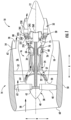
- FIG. 1 is a schematic cross-sectional view of a gas turbine engine according to one or more embodiments.
- FIG. 2 is a simplified schematic view of a gas turbine engine and a waste heat recovery system in accordance with one or more embodiments.
- FIG. 3 is a schematic view of a portion of a turbine section and an exhaust section of a gas turbine engine according to one or more embodiments.
- first”, “second”, and “third” may be used interchangeably to distinguish one component from another and are not intended to signify location or importance of the individual components.
- upstream and downstream refer to the relative direction with respect to fluid flow in a fluid pathway.
- upstream refers to the direction from which the fluid flows
- downstream refers to the direction to which the fluid flows.
- Coupled refers to both direct coupling, fixing, or attaching, as well as indirect coupling, fixing, or attaching through one or more intermediate components or features, unless otherwise specified herein.
- Approximating language is applied to modify any quantitative representation that could permissibly vary without resulting in a change in the basic function to which it is related. Accordingly, a value modified by a term or terms, such as “about”, “approximately”, and “substantially”, are not to be limited to the precise value specified.
- the approximating language may correspond to the precision of an instrument for measuring the value, or the precision of the methods or the machines for constructing or manufacturing the components and/or systems.
- the approximating language may refer to being within a 1, 2, 4, 10, 15, or 20 percent margin. These approximating margins may apply to a single value, either or both endpoints defining numerical ranges, and/or the margin for ranges between endpoints.
- turbomachine or “turbomachinery” refers to a machine including one or more compressors, a heat generating section (e.g., a combustion section), and one or more turbines that together generate a torque output.
- a heat generating section e.g., a combustion section
- turbines that together generate a torque output.
- gas turbine engine refers to an engine having a turbomachine as all or a portion of its power source.
- Example gas turbine engines include turbofan engines, turboprop engines, turbojet engines, turboshaft engines, etc., as well as hybrid-electric versions of one or more of these engines.
- combustion section refers to any heat addition system for a turbomachine.
- combustion section may refer to a section including one or more of a deflagrative combustion assembly, a rotating detonation combustion assembly, a pulse detonation combustion assembly, or other appropriate heat addition assembly.
- the combustion section may include an annular combustor, a can combustor, a cannular combustor, a trapped vortex combustor (TVC), or other appropriate combustion system, or combinations thereof.
- a “low turbine” or “low speed turbine” defines a component configured to operate at a rotational speed, such as a maximum allowable rotational speed, lower than a “high turbine” or a “high speed turbine” of the engine.
- gas turbine engines may instead employ high speed low pressure turbines that rotate at a higher speed than the conventional low pressure turbines.
- the high speed low pressure turbines may include a reducing gearbox in the fan module such that the rotation speed of the fan is reduced from the high rotation speed of the high speed low pressure turbines.
- the blades of the high speed low pressure turbines experience increased stresses compared to conventional low pressure turbines. Because an increase in size of the blades also increases an amount of stress experienced thereby, a material capability of the blades may require a size of the blades to be reduced to compensate for the increased stresses caused by the higher rotation speeds. Therefore, high speed low pressure turbines may have a limited exhaust annulus area due to blade material capability.
- the higher speeds of the blades within the high speed low pressure turbines may also result in a high exhaust Mach number. That is, the combustion gases exiting the high speed low pressure turbines and entering the exhaust section may have a high Mach number.
- the high Mach number entering the exhaust section may cause losses in waste heat recovery for heat source exchangers within the exhaust section. This loss is proportional to a square of the Mach number of the combustion gases entering the heat source exchangers.
- a counter-rotating turbine allows for larger turbine blades within high speed low pressure turbines and a more axially compact package, while reducing the exhaust Mach number and significantly reducing losses in waste heat recovery for the heat source exchangers within the exhaust section.
- the final stage low pressure turbine blades may be formed to have larger radial dimensions and thus larger annulus flow areas, which in turn reduces a Mach number of the flow entering the heat source exchanger downstream of the final stage low pressure turbine blades.
- FIG. 1 is a schematic cross-sectional view of a gas turbine engine in accordance with an exemplary embodiment of the present disclosure. More particularly, for the embodiment of FIG. 1 , the gas turbine engine is a high-bypass turbofan jet engine 10 , referred to herein as “gas turbine engine 10 .” As shown in FIG. 1 , the gas turbine engine 10 defines an axial direction A (extending parallel to a longitudinal centerline 12 provided for reference), a radial direction R, and a circumferential direction (i.e., a direction extending about the axial direction A; not depicted). In general, the gas turbine engine 10 includes a fan section 14 and a turbomachine 16 disposed downstream from the fan section 14 .
- the exemplary turbomachine 16 depicted generally includes a substantially tubular outer casing 18 that defines an annular inlet 20 .
- the outer casing 18 encases, in serial flow relationship, a compressor section including a booster or low pressure (LP) compressor 22 and a high pressure (HP) compressor 24 , a combustion section 26 , a turbine section including a high pressure (HP) turbine 28 and a low pressure (LP) turbine 30 , and an exhaust section 32 .
- the compressor section, the combustion section 26 , and the turbine section together define a core air flowpath 37 extending from the annular inlet 20 through the LP compressor 22 , the HP compressor 24 , the combustion section 26 , the HP turbine 28 , the LP turbine 30 and the exhaust section 32 .
- a high pressure (HP) shaft or a spool 34 drivingly connects the HP turbine 28 to the HP compressor 24 .
- a low pressure (LP) shaft or a spool 36 drivingly connects the LP turbine 30 to the LP compressor 22 .
- the fan section 14 includes a fan 38 having a plurality of fan blades 40 coupled to a disk 42 in a spaced apart manner. As depicted, the fan blades 40 extend outwardly from disk 42 generally along the radial direction R. The fan blades 40 and disk 42 are together rotatable about the longitudinal centerline 12 by the LP shaft or the spool 36 .
- the disk 42 is covered by rotatable spinner cone 48 aerodynamically contoured to promote an airflow through the plurality of fan blades 40 .
- the exemplary fan section 14 includes an annular fan casing or outer nacelle 50 that circumferentially surrounds the fan 38 and/or at least a portion of the turbomachine 16 .
- the outer nacelle 50 is supported relative to the turbomachine 16 by a plurality of circumferentially-spaced outlet guide vanes 52 .
- a downstream section 54 of the outer nacelle 50 extends over an outer portion of turbomachine 16 so as to define a bypass airflow passage 56 therebetween.
- a volume of air 58 enters the gas turbine engine 10 through an associated inlet 60 of the outer nacelle 50 and/or the fan section 14 .
- a first portion of air 62 from the volume of air 58 is directed or routed into the bypass airflow passage 56 and a second portion of air 64 from the volume of air 58 is directed or routed into the LP compressor 22 .
- the ratio between the first portion of air 62 and the second portion of air 64 is commonly known as a bypass ratio.
- the pressure of the second portion of air 64 is then increased as it is routed through the HP compressor 24 and into the combustion section 26 , where it is mixed with fuel and burned to provide combustion gases 66 .
- the combustion gases 66 are routed through the HP turbine 28 where a portion of thermal and/or kinetic energy from the combustion gases 66 is extracted via sequential stages of HP turbine stator vanes 68 that are coupled to an inner casing (not shown) and HP turbine rotor blades 70 that are coupled to the HP shaft or spool 34 , thus causing the HP shaft or spool 34 to rotate, thereby supporting operation of the HP compressor 24 .
- the combustion gases 66 are then routed through the LP turbine 30 where a second portion of thermal and kinetic energy is extracted from the combustion gases 66 via first stage LP turbine rotor blades 221 and second stage LP turbine rotor blades 223 that rotate together in a first direction around the longitudinal centerline 12 , and final stage LP turbine rotor blades 241 that rotate in a second direction around the longitudinal centerline 12 opposite the first direction.
- First turbine guide vanes 210 are disposed upstream of the first stage LP turbine rotor blades 221
- second turbine guide vanes 230 are disposed between the first stage LP turbine rotor blades 221 and the second stage LP turbine rotor blades 223 .
- the first stage LP turbine rotor blades 221 and the second stage LP turbine rotor blades 223 are connected via a first LP turbine spool 225 that rotates in the first direction around the longitudinal centerline 12 and is coupled to a gearbox 260 .
- the final stage LP turbine rotor blades 241 are connected to a second LP turbine spool 245 that rotates in the second direction and is also coupled to the gearbox 260 .
- the gearbox 260 is further coupled to the LP shaft or spool 36 , such that the first stage LP turbine rotor blades 221 , the second stage LP turbine rotor blades 223 , and the final stage LP turbine rotor blades 241 drive the LP shaft or spool 36 to rotate through the gearbox 260 .
- the LP turbine 30 supports operation of the LP compressor 22 and/or rotation of the fan 38 .
- the combustion gases 66 are subsequently routed through the exhaust section 32 of the turbomachine 16 to provide propulsive thrust.
- the exhaust section 32 includes a heat source exchanger 250 disposed immediately downstream of the final stage LP turbine rotor blades 241 .
- the pressure of the first portion of air 62 is substantially increased as the first portion of air 62 is routed through the bypass airflow passage 56 before it is exhausted from a fan nozzle exhaust section 78 of the gas turbine engine 10 , also providing propulsive thrust.
- the HP turbine 28 , the LP turbine 30 , and the exhaust section 32 at least partially define a hot gas path for routing the combustion gases 66 through the turbomachine 16 .
- the exemplary gas turbine engine 10 depicted in FIG. 1 is by way of example only, and in other exemplary embodiments, the gas turbine engine 10 may have any other suitable configuration.
- the gas turbine engine 10 may instead be configured as any other suitable turbomachine including, e.g., any other suitable number of shafts or spools, and excluding, e.g., the fan 38 and/or including, e.g., a gearbox between the fan 38 and the LP shaft or spool 36 , a variable pitch fan 38 , etc.
- the gas turbine engine 10 may instead be configured as, e.g., a turbojet engine, a turboshaft engine, a turboprop engine, etc., and further may be configured as an aeroderivative gas turbine engine or an industrial gas turbine engine.
- FIG. 2 a simplified, schematic view of a gas turbine engine 10 in accordance with an exemplary aspect of the present disclosure is provided.
- the exemplary gas turbine engine 10 depicted in FIG. 2 may be configured in substantially the same manner as exemplary gas turbine engine 10 described above with reference to FIG. 1 .
- the gas turbine engine 10 generally includes a fan section 14 and a turbomachine 16 .
- the turbomachine 16 includes in serial flow order a compressor section having an LP compressor 22 and an HP compressor 24 , a combustion section 26 , a turbine section including an HP turbine 28 and an LP turbine 30 , and an exhaust section 32 .
- the compressor section, the combustion section 26 , the turbine section, and the exhaust section 32 generally define a core air flowpath 37 extending therethrough.
- a fuel delivery system 80 is also included for providing a flow of fuel to the combustion section 26 of the gas turbine engine 10 , and more specifically to a combustion chamber 92 of the combustion section 26 .
- the fuel delivery system 80 generally includes a plurality of fuel lines 84 and a fuel nozzle 90 .
- the fuel nozzle 90 may receive a flow of fuel from the plurality of fuel lines 84 and further may receive compressed air from the compressor section (e.g., the HP compressor 24 ).
- the fuel nozzle 90 may accordingly provide a mixture of compressed air and fuel to the combustion chamber 92 , wherein such mixture of compressed air and fuel is combusted to generate combustion gases.
- the fuel delivery system 80 generally also includes a fuel source 82 and a pump 88 in fluid communication with the one or more fuel lines 84 , the pump 88 configured for increasing a pressure of a fuel flow from the fuel source 82 and through the one or more fuel lines 84 .
- turbomachine 16 and fan section 14 are at least partially surrounded by an outer nacelle 50 , with the turbomachine 16 supported relative to the outer nacelle 50 through a plurality of outlet guide vanes 52 .
- the outer nacelle 50 defines a bypass airflow passage 56 with the turbomachine 16 .
- a first portion 62 of an airflow from the fan section 14 is provided through the turbomachine 16 as a core airflow, and a second portion of the air 64 from the fan section 14 is provided through the bypass airflow passage 56 as a bypass airflow.
- the exemplary gas turbine engine 10 includes a waste heat recovery system 86 .
- the exemplary waste heat recovery system 86 is generally configured to extract heat from a heat source (e.g., a heat source not fully utilizing the heat being extracted therefrom) and transfer such extracted heat to a heat sink, such that the heat sink may more efficiently utilize such extracted heat.
- a heat source e.g., a heat source not fully utilizing the heat being extracted therefrom
- the waste heat recovery system 86 generally includes a heat source exchanger 250 (i.e., a heat exchanger configured to extract heat for the waste heat recovery system 86 from a heat source of the gas turbine engine 10 ), a heat sink exchanger 96 (i.e., a heat exchanger configured to transfer heat from the waste heat recovery system 86 to a heat sink of the gas turbine engine 10 ), a thermal transfer bus 98 , and a pump 100 .
- a heat source exchanger 250 i.e., a heat exchanger configured to extract heat for the waste heat recovery system 86 from a heat source of the gas turbine engine 10
- a heat sink exchanger 96 i.e., a heat exchanger configured to transfer heat from the waste heat recovery system 86 to a heat sink of the gas turbine engine 10
- a thermal transfer bus 98 i.e., a heat exchanger configured to transfer heat from the waste heat recovery system 86 to a heat sink of the gas turbine engine 10
- a thermal transfer bus 98 i.
- the heat source exchanger 250 is in thermal communication with the exhaust section 32 of the gas turbine engine 10 such that the heat source exchanger 250 extracts heat from the exhaust section 32 .
- the heat source exchanger 250 may be integrated into a strut extending through the exhaust section 32 or a liner defining at least in part the exhaust section 32 , or alternatively may be positioned at any other suitable location in thermal communication with an airflow/gases through the exhaust section 32 of the gas turbine engine 10 .
- the heat sink exchanger 96 is in thermal communication with the heat sink, which may generally be the compressor section, the fuel delivery system 80 , and/or any other section of the aircraft requiring heat.
- the heat sink exchanger 96 is in thermal communication with the compressor section at a location proximate a downstream end of the compressor section, or more specifically still with a location proximate a downstream end of the HP compressor 24 of the compressor section.
- proximate the downstream end refers to a location closer to an exit of the compressor section than an inlet to the compressor section and upstream of the combustion chamber 92 .
- the term “proximate the downstream end,” with reference to the HP compressor 24 refers to a location closer to an exit 102 of the HP compressor 24 than an inlet 104 to the HP compressor 24 and upstream of the combustion chamber 92 .
- the heat sink exchanger 96 may be integrated into, or coupled to, a strut or guide vane, such as a diffuser, positioned at the exit 102 of the HP compressor 24 and upstream of the combustion chamber 92 of the combustion section 26 .
- the heat sink exchanger 96 may be integrated into, or coupled to, one or more fuel nozzles 90 of the fuel delivery system 80 .
- the heat sink exchanger 96 is disposed in a portion of the gas turbine engine 10 upstream of the combustion section 26 .
- the heat sink exchanger 96 may be disposed within the fuel delivery system 80 upstream of the combustion section 26 , within the core air flowpath 37 upstream of the combustion section 26 , or other locations upstream of the combustion section 26 .
- the term “upstream” refers to the direction of flow and not the axial direction.
- the heat sink exchanger 96 may be forward of, aft of, or in line with the combustion section 26 in the axial direction A.
- the fuel delivery system 80 may deliver conventional fuel or, alternatively or additionally, may deliver H 2 fuel.
- the heat sink exchanger 96 is in thermal communication with the exit 102 of the HP compressor 24 of the gas turbine engine 10 .
- the “compressor exit” refers to an outlet of the HP compressor 24 .
- the heat sink exchanger 96 may add heat to an airflow through the core air flowpath 37 prior to such airflow entering the combustion chamber 92 , resulting in a more efficient gas turbine engine 10 .
- the waste heat recovery system 86 includes the thermal transfer bus 98 .
- the thermal transfer bus 98 includes a thermal transfer fluid and extends from the heat source exchanger 250 to the heat sink exchanger 96 .
- the thermal bus is configured to transfer the thermal transfer fluid from the heat source exchanger 250 (wherein the thermal transfer fluid has accepted heat from the airflow through, for the embodiment shown, the exhaust section 32 of the gas turbine engine 10 ) to the heat sink exchanger 96 (wherein the thermal transfer fluid transfers heat to the airflow through, for the embodiment shown, the exit 102 of the HP compressor 24 , or other location upstream of the combustion chamber 92 ).
- the thermal transfer bus 98 may include one or more pipes, conduits, etc. arranged in series, parallel, or some combination thereof.
- the gas turbine engine 10 may define a relatively high overall pressure ratio.
- the term overall pressure ratio refers to a ratio of a pressure of the air through the turbomachine 16 at an outlet of the compressor section (i.e., the exit 102 of the HP compressor 24 for the embodiment shown) to a pressure of the air through the turbomachine 16 at an inlet of the compressor section (i.e., an inlet 106 of the LP compressor 22 for the embodiment shown).
- the overall pressure ratio of the gas turbine engine 10 depicted in FIG. 2 may be at least about twenty-five.
- the overall pressure ratio of the gas turbine engine 10 depicted in FIG. 2 may be at least about twenty-eight, such as at least about thirty, such as at least about thirty-two, such as up to about seventy-five.
- the exemplary waste heat recovery system 86 may further include the pump 100 in fluid communication with the thermal transfer bus 98 downstream of the heat source exchanger 250 and upstream of the heat sink exchanger 96 for increasing a temperature and a pressure of the thermal transfer fluid in the thermal transfer bus 98 .
- the pump 100 may be configured to provide at least about a twenty-five pounds per square inch (“psi”) pressurize rise, such as at least about a fifty psi of pressurize rise, such as at least about a one hundred psi of pressurize rise, such as up to about five thousand psi pressure rise, in the thermal transfer fluid through the thermal transfer bus 98 , and similarly may be configured to provide at least about one hundred fifty (150) degrees Celsius temperature rise, such as at least about two hundred fifty (250) degrees Celsius temperature rise, and up to about one thousand (1,000) degrees Celsius temperature rise, in the thermal transfer fluid through the thermal transfer bus 98 .
- psi pounds per square inch
- the pump 100 may be powered through, e.g., one or more of the shafts or spools of the gas turbine engine 10 , or alternatively may be powered by an electric motor, hydraulic motor, pneumatic motor, or any other suitable power source. In other exemplary embodiments, however, the pump 100 may have any other suitable configuration. For example, in other embodiments, the pump 100 may be configured to create any other suitable temperature and/or pressure rise, or some other suitable device or configuration may be provided to increase a temperature and/or pressure of the thermal fluid through the thermal transfer bus 98 and provide for the flow of thermal fluid through the thermal transfer bus 98 .
- the exemplary thermal transfer bus 98 is a closed loop thermal transfer bus 98 further extending from the heat sink exchanger 96 back to the heat source exchanger 250 .
- the exemplary waste heat recovery system 86 further includes an expansion device in fluid communication with the thermal transfer bus 98 downstream of the heat sink exchanger 96 and upstream of the heat source exchanger 250 .
- the expansion device may be any suitable expansion device.
- the expansion device is configured as a turbine 114 in fluid communication with the thermal transfer bus 98 downstream of the heat sink exchanger 96 and upstream of the heat source exchanger 250 .
- the turbine 114 may extract additional energy from the thermal transfer fluid, increasing an efficiency of the waste heat recovery system 86 and the gas turbine engine 10 .
- inclusion of the expansion device may generally allow for the reduction of a temperature of the thermal transfer fluid to a relatively low temperature such that the thermal transfer fluid may accept heat from the heat source through the heat source exchanger 250 .
- the expansion device may reduce a temperature of the thermal transfer fluid at least about one hundred degrees Celsius, such as at least about one hundred and fifty degrees Celsius, such as up to about one thousand degrees Celsius.
- the expansion device may not be configured to extract additional work form the thermal transfer fluid, and instead may simply be configured to expand the thermal transfer fluid (e.g., through an increasing cross-sectional area) to reduce a temperature and a pressure of the thermal transfer fluid.
- the expansion device/turbine 114 is depicted schematically inward of the core air flowpath 37 along a radial direction R of the gas turbine engine 10 of FIG. 2 , in other embodiments, the expansion device/turbine 114 may instead be positioned outward of the core air flowpath 37 along the radial direction R.
- the thermal transfer fluid may be a single phase thermal transfer fluid during operation of the waste heat recovery system 86 .
- the thermal transfer fluid may remain in substantially a liquid phase during operation.
- the thermal transfer fluid may be a phase change thermal transfer fluid during operation of the waste heat recovery system 86 .
- the waste heat recovery system 86 may generally operate on a refrigeration cycle, such that the thermal transfer fluid changes between liquid and gaseous phases during operation of the waste heat recovery system 86 .
- the thermal transfer fluid may be in a supercritical phase during one or more stages of operation, or during all operations.
- the thermal transfer fluid may be a supercritical carbon dioxide during certain operations or all operations of the waste heat recovery system 86 .
- the exemplary gas turbine engine 10 and waste heat recovery system 86 depicted in FIG. 2 is, however, provided by way of example only. In other embodiments, the waste heat recovery system 86 may have any other suitable configuration. As noted above, the heat sink exchanger 96 may be disposed in any other location that may use the heat from the waste heat recovery system 86 to improve, e.g., efficiency.
- FIG. 3 is a schematic view of a portion of a turbine section and an exhaust section 32 of a gas turbine engine according to one or more embodiments. More specifically, FIG. 3 shows an LP turbine 30 and a heat source exchanger 250 disposed within the exhaust section 32 according to one or more embodiments.
- the turbine section and exhaust section 32 of FIG. 3 may be configured in a similar manner as the exemplary turbine section and exhaust section 32 described above with reference to FIG. 1 .
- the turbine section is generally configured as part of a gas turbine engine defining a radial direction R and an axial direction A.
- the LP turbine 30 includes, in serial flow order and along the axial direction A, first turbine guide vanes 210 , first stage LP turbine rotor blades 221 , second turbine guide vanes 230 , second stage LP turbine rotor blades 223 , and final stage LP turbine rotor blades 241 .
- the exhaust section 32 according to one or more embodiments is disposed downstream of the LP turbine 30 in the axial direction A and includes the heat source exchanger 250 also downstream of the final stage LP turbine rotor blades 241 in the axial direction A.
- the gas turbine engine further includes a waste heat recovery system 86 with a thermal transfer bus 98 having a thermal transfer fluid configured to flow therethrough.
- the heat source exchanger 250 is part of the waste heat recovery system 86 and is coupled to the thermal transfer bus 98 , such that the thermal transfer fluid passing through the thermal transfer bus 98 passes through the heat source exchanger 250 to extract heat from the exhaust section 32 of the gas turbine engine 10 .
- the heat source exchanger 250 is a frame-integrated heat exchanger that is integrated into the frame of the turbomachine 16 . According to one or more embodiments, the heat source exchanger 250 is a heat exchanger formed separately from the frame of the turbomachine 16 .
- the first turbine guide vanes 210 are directly upstream of the first stage LP turbine rotor blades 221 , the first stage LP turbine rotor blades 221 are directly upstream of the second turbine guide vanes 230 , the second turbine guide vanes 230 are directly upstream of the second stage LP turbine rotor blades 223 , and the second stage LP turbine rotor blades 223 are directly upstream of the final stage LP turbine rotor blades 241 , and the final stage LP turbine rotor blades 241 are directly upstream of the heat source exchanger 250 .
- the first turbine guide vanes 210 and the second turbine guide vanes 230 are stationary.
- FIGS. 1 and 3 show two stages of turbine rotor blades with a single stage of turbine guide vanes therebetween upstream of the final stage LP turbine rotor blades 241
- one or more embodiments may include additional stages of turbine rotor blades and turbine guide vanes.
- the LP turbine 30 may further include third turbine guide vanes and third stage LP turbine rotor blades in serial order downstream of the second stage LP turbine rotor blades 223 and may further include fourth turbine guide vanes and fourth stage LP turbine rotor blades in serial order downstream of the third stage LP turbine rotor blades, and so on.
- the first stage LP turbine rotor blades 221 and the second stage LP turbine rotor blades 223 rotate in a first direction around the longitudinal centerline 12 .
- the first stage LP turbine rotor blades 221 and the second stage LP turbine rotor blades 223 are connected to each other via a first LP turbine spool 225 that is driven by the first stage LP turbine rotor blades 221 and the second stage LP turbine rotor blades 223 to rotate in the first direction around the longitudinal centerline 12 .
- the first LP turbine spool 225 is coupled to a gearbox 260 .
- the additional stage(s) of LP turbine rotor blades are also connected to the first stage LP turbine rotor blades 221 and the second stage LP turbine rotor blades 223 via the first LP turbine spool 225 .
- the final stage LP turbine rotor blades 241 are connected to a second LP turbine spool 245 and rotate in a second direction around the longitudinal centerline 12 , which is opposite the first direction.
- the final stage LP turbine rotor blades 241 are connected to the second LP turbine spool 245 that is driven by the final stage LP turbine rotor blades 241 to rotate in the second direction.
- the second LP turbine spool 245 is also coupled to the gearbox 260 .
- the gearbox 260 is further coupled to the LP shaft or spool 36 , such that the first stage LP turbine rotor blades 221 , the second stage LP turbine rotor blades 223 , and the final stage LP turbine rotor blades 241 drive the LP shaft or spool 36 through the gearbox 260 .
- the LP turbine 30 supports operation of the LP compressor 22 and/or rotation of the fan 38 (see FIG. 1 ).
- the gearbox 260 is disposed partially or entirely on an inner side of the LP turbine 30 in the radial direction R.
- the gearbox 260 may be structured as a planetary gear system in which that the LP shaft or spool 36 is fixed to or connected to a sun gear 261 , the second LP turbine spool 245 is connected to planet gears 263 that are disposed around the sun gear 261 and are meshed with the sun gear 261 , and the first LP turbine spool 225 is fixed to or connected to a ring gear 265 disposed around the planet gears 263 and is meshed with the planet gears 263 .
- first LP turbine spool 225 and the LP shaft or spool 36 rotate in the first direction around the longitudinal centerline 12 , with the first LP turbine spool 225 rotating at a higher speed than the LP shaft or spool 36 , and the second LP turbine spool 245 rotates in the second direction at a lower speed than the first LP turbine spool 225 .
- the final stage LP turbine rotor blades 241 have a significantly greater height in the radial direction R than the first stage LP turbine rotor blades 221 and the second stage LP turbine rotor blades 223 .
- the final stage LP turbine rotor blades 241 also have a significantly greater height in the radial direction R than final stage LP turbine rotor blades of conventional high speed low pressure turbines that rotate at the same speed in the same direction as the preceding stages of LP turbine rotor blades.
- This greater height is possible due to the reduced speed of the final stage LP turbine rotor blades 241 rotating in the second direction, as the reduced speed reduces the stresses experienced by the final stage LP turbine rotor blades 241 compared to the aforementioned final stage LP turbine rotor blades of conventional high speed low pressure turbines. Furthermore, the reduction in stresses experienced by the final stage LP turbine rotor blades 241 may also enable materials that could not withstand the greater stresses experienced by the final stage LP turbine rotor blades of conventional high speed low pressure turbines.
- the first stage LP turbine rotor blades 221 , the second stage LP turbine rotor blades 223 , and the final stage LP turbine rotor blades 241 are formed of nickel alloys, or are formed of a material that comprises nickel alloys. According to one or more embodiments, the final stage LP turbine rotor blades 241 are formed of a different material from the first stage LP turbine rotor blades 221 and the second stage LP turbine rotor blades 223 . According to one or more embodiments, the final stage LP turbine rotor blades 241 are formed of titanium aluminide or a material comprising titanium aluminide.
- the lower speed of rotation of the final stage LP turbine rotor blades 241 also reduces a Mach number of the combustion gases exiting the LP turbine 30 and entering the exhaust section 32 .
- combustion gases may exit conventional high speed low pressure turbines and enter the exhaust section at a Mach number equal to around 1 ⁇ 2 Ma.
- the LP turbine 30 is structured such that combustion gases exit the LP turbine 30 and enter the exhaust section 32 at a Mach number of 1 ⁇ 3 Ma or lower. With a Mach number of 1 ⁇ 3 Ma or less, a frame-integrated heat exchanger that is integrated into the frame of the turbomachine 16 may be employed as the heat source exchanger 250 in the exhaust section 32 .
- the LP turbine 30 is structured such that combustion gases exits the LP turbine 30 and enters the exhaust section 32 at a Mach number of 1 ⁇ 4 Ma or less.
- a traditional heat exchanger separate from the frame of the turbomachine 16 may be employed as the heat source exchanger 250 in the exhaust section 32 .
- a turbine section and an exhaust section for a gas turbine engine comprises a low pressure (LP) turbine comprising first stage LP turbine blades that rotate in a first direction at a first speed, and final stage LP turbine blades downstream of the first stage LP turbine blades that rotate in a second direction opposite the first direction at a second speed, wherein the second speed is lower than the first speed.
- LP low pressure
- the LP turbine further comprises second stage LP turbine blades downstream of the first stage LP turbine blades and upstream of the final stage LP turbine blades that rotate in the first direction at the first speed, and guide vanes disposed between the first stage LP turbine blades and the second stage LP turbine blades.
- the turbine section and the exhaust section of one or more of these clauses further comprising a heat source exchanger disposed downstream of the final stage LP turbine blades.
- first stage LP turbine blades are connected to a first LP turbine spool
- final stage LP turbine blades are connected to a second LP turbine spool
- the LP turbine further comprises a gearbox to which the first LP turbine spool and the second LP turbine spool are coupled.
- the gearbox comprises a planetary gear system, wherein a ring gear of the planetary gear system is connected to the first LP turbine spool, wherein planet gears of the planetary gear system are connected to the second LP turbine spool, and wherein a sun gear of the planetary gear system is configured to be connected to an LP shaft or a spool that is connected to a fan of the gas turbine engine.
- the turbine section and the exhaust section of one or more of these clauses further comprising a high pressure (HP) turbine located upstream of the LP turbine.
- HP high pressure
- a turbine section and an exhaust section of a gas turbine engine comprises a low pressure (LP) turbine comprising a plurality of stages of LP turbine blades that rotate in a first direction at a first speed, and final stage LP turbine blades downstream of the plurality of stages of LP turbine blades that rotate in a second direction opposite the first direction at a second speed, wherein the second speed is lower than the first speed.
- LP low pressure
- the LP turbine further comprises a drum positioned inward of an airflow path through the LP turbine along a radial direction of the gas turbine engine, wherein the plurality of stages of LP turbine blades that rotate in the first direction are coupled together with the drum, wherein each of the final stages LP turbine blades includes an outer end along the radial direction, and wherein each of the final stages LP turbine blades is mechanically isolated at the outer end.
- the LP turbine further comprises guide vanes disposed between adjacent stages of the plurality of stages of LP turbine blades.
- the turbine section and the exhaust section of one or more of these clauses further comprising a heat source exchanger disposed downstream of the final stage LP turbine blades.
- each of the plurality of stages of LP turbine blades is connected to a first LP turbine spool, wherein the final stage LP turbine blades are connected to a second LP turbine spool, and wherein the LP turbine further comprises a gearbox to which the first LP turbine spool and the second LP turbine spool are coupled.
- the gearbox comprises a planetary gear system, wherein a ring gear of the planetary gear system is connected to the first LP turbine spool, wherein planet gears of the planetary gear system are connected to the second LP turbine spool, and wherein a sun gear of the planetary gear system is configured to be connected to a LP shaft or spool that is connected to a fan of the gas turbine engine.
- a gas turbine engine comprises a low pressure (LP) turbine comprising a plurality of stages of LP turbine blades that rotate in a first direction at a first speed, and final stage LP turbine blades downstream of the plurality of stages of LP turbine blades that rotate in a second direction opposite the first direction at a second speed, wherein the second speed is lower than the first speed.
- LP low pressure
- each of the plurality of stages of LP turbine blades is connected to a first LP turbine spool, wherein the final stage LP turbine blades are connected to a second LP turbine spool, and wherein the LP turbine further comprises a gearbox to which the first LP turbine spool and the second LP turbine spool are coupled.
- the gearbox comprises a planetary gear system, wherein a ring gear of the planetary gear system is connected to the first LP turbine spool, wherein planet gears of the planetary gear system are connected to the second LP turbine spool, and wherein a sun gear of the planetary gear system is connected to an LP shaft or a spool that is connected to a fan of the gas turbine engine.
- the gas turbine engine of one or more of these clauses further comprising a heat recovery system, wherein the heat recovery system comprises a heat source exchanger disposed downstream of the final stage LP turbine blades, and a heat sink exchanger disposed in a portion of the gas turbine engine upstream of a combustion section of the gas turbine engine.
- the heat recovery system comprises a heat source exchanger disposed downstream of the final stage LP turbine blades, and a heat sink exchanger disposed in a portion of the gas turbine engine upstream of a combustion section of the gas turbine engine.
Landscapes
- Engineering & Computer Science (AREA)
- Chemical & Material Sciences (AREA)
- Combustion & Propulsion (AREA)
- Mechanical Engineering (AREA)
- General Engineering & Computer Science (AREA)
- Structures Of Non-Positive Displacement Pumps (AREA)
Abstract
Description
Claims (19)
Priority Applications (1)
| Application Number | Priority Date | Filing Date | Title |
|---|---|---|---|
| US17/713,649 US12071889B2 (en) | 2022-04-05 | 2022-04-05 | Counter-rotating turbine |
Applications Claiming Priority (1)
| Application Number | Priority Date | Filing Date | Title |
|---|---|---|---|
| US17/713,649 US12071889B2 (en) | 2022-04-05 | 2022-04-05 | Counter-rotating turbine |
Publications (2)
| Publication Number | Publication Date |
|---|---|
| US20230340906A1 US20230340906A1 (en) | 2023-10-26 |
| US12071889B2 true US12071889B2 (en) | 2024-08-27 |
Family
ID=88416068
Family Applications (1)
| Application Number | Title | Priority Date | Filing Date |
|---|---|---|---|
| US17/713,649 Active 2042-04-05 US12071889B2 (en) | 2022-04-05 | 2022-04-05 | Counter-rotating turbine |
Country Status (1)
| Country | Link |
|---|---|
| US (1) | US12071889B2 (en) |
Cited By (2)
| Publication number | Priority date | Publication date | Assignee | Title |
|---|---|---|---|---|
| US20240093644A1 (en) * | 2022-09-16 | 2024-03-21 | General Electric Company | Gas turbine engines with a fuel cell assembly |
| US20250146440A1 (en) * | 2023-11-07 | 2025-05-08 | Rtx Corporation | Strut microtube counterflow evaporator |
Citations (64)
| Publication number | Priority date | Publication date | Assignee | Title |
|---|---|---|---|---|
| US3135496A (en) | 1962-03-02 | 1964-06-02 | Gen Electric | Axial flow turbine with radial temperature gradient |
| US4502837A (en) | 1982-09-30 | 1985-03-05 | General Electric Company | Multi stage centrifugal impeller |
| US4981414A (en) | 1988-05-27 | 1991-01-01 | Sheets Herman E | Method and apparatus for producing fluid pressure and controlling boundary layer |
| US5010729A (en) * | 1989-01-03 | 1991-04-30 | General Electric Company | Geared counterrotating turbine/fan propulsion system |
| US5152661A (en) | 1988-05-27 | 1992-10-06 | Sheets Herman E | Method and apparatus for producing fluid pressure and controlling boundary layer |
| US5209644A (en) | 1991-01-11 | 1993-05-11 | United Technologies Corporation | Flow directing element for the turbine of a rotary machine and method of operation therefor |
| US5352092A (en) | 1993-11-24 | 1994-10-04 | Westinghouse Electric Corporation | Light weight steam turbine blade |
| US5616004A (en) | 1995-04-19 | 1997-04-01 | Valeo Thermique Moteur | Axial flow fan |
| US5779443A (en) | 1994-08-30 | 1998-07-14 | Gec Alsthom Limited | Turbine blade |
| US6375419B1 (en) | 1995-06-02 | 2002-04-23 | United Technologies Corporation | Flow directing element for a turbine engine |
| US6488470B1 (en) * | 1999-08-03 | 2002-12-03 | Jerzy A. Owczarek | Annular flow diffusers for gas turbines |
| US6709239B2 (en) | 2001-06-27 | 2004-03-23 | Bharat Heavy Electricals Ltd. | Three dimensional blade |
| US6711887B2 (en) | 2002-08-19 | 2004-03-30 | General Electric Co. | Aircraft gas turbine engine with tandem non-interdigitated counter rotating low pressure turbines |
| US6799948B2 (en) | 2001-01-12 | 2004-10-05 | Mitsubishi Heavy Industries, Ltd. | Blade of a gas turbine |
| US6802474B2 (en) | 2002-10-08 | 2004-10-12 | Honda Giken Kogyo Kabushiki Kaisha | Advanced high turning compressor airfoils |
| US20050241292A1 (en) * | 2004-03-19 | 2005-11-03 | Rolls-Royce Plc | Turbine engine arrangements |
| US7175393B2 (en) | 2004-03-31 | 2007-02-13 | Bharat Heavy Electricals Limited | Transonic blade profiles |
| US7179058B2 (en) | 2004-03-21 | 2007-02-20 | Bharat Heavy Electricals Limited | Aerodynamically wide range applicable cylindrical blade profiles |
| US20070053779A1 (en) | 2005-09-05 | 2007-03-08 | Volker Guemmer | Blade of a turbomachine with block-wise defined profile skeleton line |
| US7204676B2 (en) | 2004-05-14 | 2007-04-17 | Pratt & Whitney Canada Corp. | Fan blade curvature distribution for high core pressure ratio fan |
| US7246484B2 (en) * | 2003-08-25 | 2007-07-24 | General Electric Company | FLADE gas turbine engine with counter-rotatable fans |
| US7374403B2 (en) | 2005-04-07 | 2008-05-20 | General Electric Company | Low solidity turbofan |
| US20080131272A1 (en) | 2006-11-30 | 2008-06-05 | General Electric Company | Advanced booster system |
| US20080149205A1 (en) | 2006-12-20 | 2008-06-26 | General Electric Company | System and method for reducing wake |
| US7416382B2 (en) | 2005-12-19 | 2008-08-26 | Rolls-Royce Deutschland Ltd & Co Kg | Turbomachine with variable stator |
| US20090123276A1 (en) | 2007-11-09 | 2009-05-14 | Alstom Technology Ltd | Steam turbine |
| US20110129346A1 (en) | 2009-12-02 | 2011-06-02 | Minebea Co., Ltd. | Fan Stall Inhibitor |
| US7967571B2 (en) | 2006-11-30 | 2011-06-28 | General Electric Company | Advanced booster rotor blade |
| US8157518B2 (en) | 2007-03-05 | 2012-04-17 | Xcelaero Corporation | Low camber microfan |
| US8166748B2 (en) * | 2008-11-21 | 2012-05-01 | General Electric Company | Gas turbine engine booster having rotatable radially inwardly extending blades and non-rotatable vanes |
| US8292570B2 (en) | 2008-01-25 | 2012-10-23 | United Technologies Corporation | Low pressure turbine with counter-rotating drives for single spool |
| US8337154B2 (en) | 2007-03-05 | 2012-12-25 | Xcelaero Corporation | High efficiency cooling fan |
| US20130089415A1 (en) | 2011-10-06 | 2013-04-11 | Barry J. Brown | Gas turbine with optimized airfoil element angles |
| US8439646B2 (en) | 2009-07-17 | 2013-05-14 | Rolls-Royce Deutschland Ltd & Co Kg | Engine blade with excessive leading edge loading |
| US8468826B2 (en) | 2010-04-19 | 2013-06-25 | Honeywell International Inc. | Axial turbine wheel |
| US8573946B2 (en) | 2009-06-22 | 2013-11-05 | Rolls-Royce Plc | Compressor blade |
| US8678757B2 (en) | 2008-06-13 | 2014-03-25 | Siemens Aktiengesellschaft | Vane or blade for an axial flow compressor |
| US20140133982A1 (en) | 2011-04-15 | 2014-05-15 | Centre De Recherche En Aeronautique Asbl-Cenaero | Propulsion device having unducted counter-rotating and coaxial rotors |
| US20140234095A1 (en) | 2012-10-01 | 2014-08-21 | Rolls-Royce Plc | Aerofoil for axial-flow machine |
| US9046111B2 (en) | 2010-02-24 | 2015-06-02 | Rolls-Royce Plc | Compressor aerofoil |
| US9080512B2 (en) | 2012-02-29 | 2015-07-14 | United Technologies Corporation | Counter-rotating low pressure turbine with gear system mounted to mid turbine frame |
| US20150284070A1 (en) | 2012-10-23 | 2015-10-08 | General Electric Company | Unducted thrust producing system |
| US9200518B2 (en) | 2013-10-24 | 2015-12-01 | Honeywell International Inc. | Axial turbine wheel with curved leading edge |
| US20160052621A1 (en) | 2009-07-10 | 2016-02-25 | Peter Ireland | Energy efficiency improvements for turbomachinery |
| US20160177723A1 (en) | 2014-12-19 | 2016-06-23 | Siemens Energy, Inc. | Turbine airfoil with optimized airfoil element angles |
| US20160195010A1 (en) | 2014-07-15 | 2016-07-07 | United Technologies Corporation | Vaneless counterrotating turbine |
| EP3124794A1 (en) | 2015-07-30 | 2017-02-01 | Mitsubishi Hitachi Power Systems, Ltd. | Axial flow compressor, gas turbine including the same, and stator blade of axial flow compressor |
| US9777578B2 (en) | 2012-12-27 | 2017-10-03 | Mitsubishi Heavy Industries, Ltd. | Radial turbine blade |
| US9790796B2 (en) | 2013-09-19 | 2017-10-17 | General Electric Company | Systems and methods for modifying a pressure side on an airfoil about a trailing edge |
| US9945266B2 (en) | 2014-08-28 | 2018-04-17 | General Electric Company | Combined cycle power plant thermal energy conservation |
| US20180112547A1 (en) | 2016-10-26 | 2018-04-26 | General Electric Company | Turbine airfoil trailing edge coolant passage created by cover |
| US20180363554A1 (en) | 2017-06-16 | 2018-12-20 | General Electric Company | High tip speed gas turbine engine |
| US20190048724A1 (en) | 2017-08-11 | 2019-02-14 | General Electric Company | Low-noise airfoil for an open rotor |
| US20190063313A1 (en) | 2017-08-28 | 2019-02-28 | Mustafa Rez | Disc Turbine Engine |
| US20190301286A1 (en) | 2018-03-28 | 2019-10-03 | United Technologies Corporation | Airfoils for gas turbine engines |
| US20200003157A1 (en) * | 2017-02-08 | 2020-01-02 | General Electric Company | Counter Rotating Turbine with Reversing Reduction Gearbox |
| US10577956B2 (en) | 2017-03-03 | 2020-03-03 | Rolls-Royce Plc | Gas turbine engine vanes |
| US10697471B2 (en) | 2017-03-03 | 2020-06-30 | Rolls-Royce Plc | Gas turbine engine vanes |
| US10830130B2 (en) * | 2012-04-25 | 2020-11-10 | Raytheon Technologies Corporation | Geared turbofan with three turbines all counter-rotating |
| US20210087940A1 (en) | 2019-09-24 | 2021-03-25 | Rolls-Royce Plc | Stator vane ring or ring segment |
| US11015449B2 (en) | 2018-12-07 | 2021-05-25 | Mitsubishi Heavy Industries Compressor Corporation | Steam turbine blade and steam turbine |
| US20210189883A1 (en) | 2016-08-09 | 2021-06-24 | Mitsubishi Heavy Industries Compressor Corporation | Blade of steam turbine and steam turbine |
| US20210270137A1 (en) | 2020-02-11 | 2021-09-02 | General Electric Company | Turbine engine with airfoil having high acceleration and low blade turning |
| US20210310417A1 (en) | 2020-02-05 | 2021-10-07 | Ge Avio S.R.L. | Gearbox for an engine |
-
2022
- 2022-04-05 US US17/713,649 patent/US12071889B2/en active Active
Patent Citations (73)
| Publication number | Priority date | Publication date | Assignee | Title |
|---|---|---|---|---|
| US3135496A (en) | 1962-03-02 | 1964-06-02 | Gen Electric | Axial flow turbine with radial temperature gradient |
| US4502837A (en) | 1982-09-30 | 1985-03-05 | General Electric Company | Multi stage centrifugal impeller |
| US4981414A (en) | 1988-05-27 | 1991-01-01 | Sheets Herman E | Method and apparatus for producing fluid pressure and controlling boundary layer |
| US5152661A (en) | 1988-05-27 | 1992-10-06 | Sheets Herman E | Method and apparatus for producing fluid pressure and controlling boundary layer |
| US5010729A (en) * | 1989-01-03 | 1991-04-30 | General Electric Company | Geared counterrotating turbine/fan propulsion system |
| US5209644A (en) | 1991-01-11 | 1993-05-11 | United Technologies Corporation | Flow directing element for the turbine of a rotary machine and method of operation therefor |
| US5352092A (en) | 1993-11-24 | 1994-10-04 | Westinghouse Electric Corporation | Light weight steam turbine blade |
| US5779443A (en) | 1994-08-30 | 1998-07-14 | Gec Alsthom Limited | Turbine blade |
| US5616004A (en) | 1995-04-19 | 1997-04-01 | Valeo Thermique Moteur | Axial flow fan |
| US6375419B1 (en) | 1995-06-02 | 2002-04-23 | United Technologies Corporation | Flow directing element for a turbine engine |
| US6488470B1 (en) * | 1999-08-03 | 2002-12-03 | Jerzy A. Owczarek | Annular flow diffusers for gas turbines |
| US6799948B2 (en) | 2001-01-12 | 2004-10-05 | Mitsubishi Heavy Industries, Ltd. | Blade of a gas turbine |
| US6709239B2 (en) | 2001-06-27 | 2004-03-23 | Bharat Heavy Electricals Ltd. | Three dimensional blade |
| US6711887B2 (en) | 2002-08-19 | 2004-03-30 | General Electric Co. | Aircraft gas turbine engine with tandem non-interdigitated counter rotating low pressure turbines |
| US6802474B2 (en) | 2002-10-08 | 2004-10-12 | Honda Giken Kogyo Kabushiki Kaisha | Advanced high turning compressor airfoils |
| US7246484B2 (en) * | 2003-08-25 | 2007-07-24 | General Electric Company | FLADE gas turbine engine with counter-rotatable fans |
| US20050241292A1 (en) * | 2004-03-19 | 2005-11-03 | Rolls-Royce Plc | Turbine engine arrangements |
| US7451592B2 (en) | 2004-03-19 | 2008-11-18 | Rolls-Royce Plc | Counter-rotating turbine engine including a gearbox |
| US7179058B2 (en) | 2004-03-21 | 2007-02-20 | Bharat Heavy Electricals Limited | Aerodynamically wide range applicable cylindrical blade profiles |
| US7175393B2 (en) | 2004-03-31 | 2007-02-13 | Bharat Heavy Electricals Limited | Transonic blade profiles |
| US7204676B2 (en) | 2004-05-14 | 2007-04-17 | Pratt & Whitney Canada Corp. | Fan blade curvature distribution for high core pressure ratio fan |
| US7374403B2 (en) | 2005-04-07 | 2008-05-20 | General Electric Company | Low solidity turbofan |
| US20070053779A1 (en) | 2005-09-05 | 2007-03-08 | Volker Guemmer | Blade of a turbomachine with block-wise defined profile skeleton line |
| US7419353B2 (en) | 2005-09-05 | 2008-09-02 | Rolls-Royce Deutschland Ltd & Co Kg | Blade of a turbomachine with block-wise defined profile skeleton line |
| US7416382B2 (en) | 2005-12-19 | 2008-08-26 | Rolls-Royce Deutschland Ltd & Co Kg | Turbomachine with variable stator |
| US8292574B2 (en) | 2006-11-30 | 2012-10-23 | General Electric Company | Advanced booster system |
| US20080131272A1 (en) | 2006-11-30 | 2008-06-05 | General Electric Company | Advanced booster system |
| US8517677B2 (en) | 2006-11-30 | 2013-08-27 | General Electric Company | Advanced booster system |
| US7967571B2 (en) | 2006-11-30 | 2011-06-28 | General Electric Company | Advanced booster rotor blade |
| US20120237344A1 (en) | 2006-11-30 | 2012-09-20 | General Electric Company | Advanced booster system |
| US20080149205A1 (en) | 2006-12-20 | 2008-06-26 | General Electric Company | System and method for reducing wake |
| US8157518B2 (en) | 2007-03-05 | 2012-04-17 | Xcelaero Corporation | Low camber microfan |
| US8337154B2 (en) | 2007-03-05 | 2012-12-25 | Xcelaero Corporation | High efficiency cooling fan |
| US20090123276A1 (en) | 2007-11-09 | 2009-05-14 | Alstom Technology Ltd | Steam turbine |
| US8292570B2 (en) | 2008-01-25 | 2012-10-23 | United Technologies Corporation | Low pressure turbine with counter-rotating drives for single spool |
| US8678757B2 (en) | 2008-06-13 | 2014-03-25 | Siemens Aktiengesellschaft | Vane or blade for an axial flow compressor |
| US8166748B2 (en) * | 2008-11-21 | 2012-05-01 | General Electric Company | Gas turbine engine booster having rotatable radially inwardly extending blades and non-rotatable vanes |
| US8573946B2 (en) | 2009-06-22 | 2013-11-05 | Rolls-Royce Plc | Compressor blade |
| US20160052621A1 (en) | 2009-07-10 | 2016-02-25 | Peter Ireland | Energy efficiency improvements for turbomachinery |
| US8439646B2 (en) | 2009-07-17 | 2013-05-14 | Rolls-Royce Deutschland Ltd & Co Kg | Engine blade with excessive leading edge loading |
| US20110129346A1 (en) | 2009-12-02 | 2011-06-02 | Minebea Co., Ltd. | Fan Stall Inhibitor |
| US9046111B2 (en) | 2010-02-24 | 2015-06-02 | Rolls-Royce Plc | Compressor aerofoil |
| US8468826B2 (en) | 2010-04-19 | 2013-06-25 | Honeywell International Inc. | Axial turbine wheel |
| US20140133982A1 (en) | 2011-04-15 | 2014-05-15 | Centre De Recherche En Aeronautique Asbl-Cenaero | Propulsion device having unducted counter-rotating and coaxial rotors |
| US20130089415A1 (en) | 2011-10-06 | 2013-04-11 | Barry J. Brown | Gas turbine with optimized airfoil element angles |
| US8864457B2 (en) | 2011-10-06 | 2014-10-21 | Siemens Energy, Inc. | Gas turbine with optimized airfoil element angles |
| US9080512B2 (en) | 2012-02-29 | 2015-07-14 | United Technologies Corporation | Counter-rotating low pressure turbine with gear system mounted to mid turbine frame |
| US10830130B2 (en) * | 2012-04-25 | 2020-11-10 | Raytheon Technologies Corporation | Geared turbofan with three turbines all counter-rotating |
| US20140234095A1 (en) | 2012-10-01 | 2014-08-21 | Rolls-Royce Plc | Aerofoil for axial-flow machine |
| US20150284070A1 (en) | 2012-10-23 | 2015-10-08 | General Electric Company | Unducted thrust producing system |
| US9777578B2 (en) | 2012-12-27 | 2017-10-03 | Mitsubishi Heavy Industries, Ltd. | Radial turbine blade |
| US9790796B2 (en) | 2013-09-19 | 2017-10-17 | General Electric Company | Systems and methods for modifying a pressure side on an airfoil about a trailing edge |
| US9200518B2 (en) | 2013-10-24 | 2015-12-01 | Honeywell International Inc. | Axial turbine wheel with curved leading edge |
| US20160195010A1 (en) | 2014-07-15 | 2016-07-07 | United Technologies Corporation | Vaneless counterrotating turbine |
| US9945266B2 (en) | 2014-08-28 | 2018-04-17 | General Electric Company | Combined cycle power plant thermal energy conservation |
| US20160177723A1 (en) | 2014-12-19 | 2016-06-23 | Siemens Energy, Inc. | Turbine airfoil with optimized airfoil element angles |
| US9797267B2 (en) | 2014-12-19 | 2017-10-24 | Siemens Energy, Inc. | Turbine airfoil with optimized airfoil element angles |
| EP3124794A1 (en) | 2015-07-30 | 2017-02-01 | Mitsubishi Hitachi Power Systems, Ltd. | Axial flow compressor, gas turbine including the same, and stator blade of axial flow compressor |
| US11149549B2 (en) | 2016-08-09 | 2021-10-19 | Mitsubishi Heavy Industries Compressor Corporation | Blade of steam turbine and steam turbine |
| US20210189883A1 (en) | 2016-08-09 | 2021-06-24 | Mitsubishi Heavy Industries Compressor Corporation | Blade of steam turbine and steam turbine |
| US20180112547A1 (en) | 2016-10-26 | 2018-04-26 | General Electric Company | Turbine airfoil trailing edge coolant passage created by cover |
| US10233761B2 (en) | 2016-10-26 | 2019-03-19 | General Electric Company | Turbine airfoil trailing edge coolant passage created by cover |
| US20200003157A1 (en) * | 2017-02-08 | 2020-01-02 | General Electric Company | Counter Rotating Turbine with Reversing Reduction Gearbox |
| US10577956B2 (en) | 2017-03-03 | 2020-03-03 | Rolls-Royce Plc | Gas turbine engine vanes |
| US10697471B2 (en) | 2017-03-03 | 2020-06-30 | Rolls-Royce Plc | Gas turbine engine vanes |
| US20180363554A1 (en) | 2017-06-16 | 2018-12-20 | General Electric Company | High tip speed gas turbine engine |
| US20190048724A1 (en) | 2017-08-11 | 2019-02-14 | General Electric Company | Low-noise airfoil for an open rotor |
| US20190063313A1 (en) | 2017-08-28 | 2019-02-28 | Mustafa Rez | Disc Turbine Engine |
| US20190301286A1 (en) | 2018-03-28 | 2019-10-03 | United Technologies Corporation | Airfoils for gas turbine engines |
| US11015449B2 (en) | 2018-12-07 | 2021-05-25 | Mitsubishi Heavy Industries Compressor Corporation | Steam turbine blade and steam turbine |
| US20210087940A1 (en) | 2019-09-24 | 2021-03-25 | Rolls-Royce Plc | Stator vane ring or ring segment |
| US20210310417A1 (en) | 2020-02-05 | 2021-10-07 | Ge Avio S.R.L. | Gearbox for an engine |
| US20210270137A1 (en) | 2020-02-11 | 2021-09-02 | General Electric Company | Turbine engine with airfoil having high acceleration and low blade turning |
Non-Patent Citations (1)
| Title |
|---|
| Gas Turbine Performance by Philip Walsh and Paul Fletcher (Year: 1998). * |
Cited By (4)
| Publication number | Priority date | Publication date | Assignee | Title |
|---|---|---|---|---|
| US20240093644A1 (en) * | 2022-09-16 | 2024-03-21 | General Electric Company | Gas turbine engines with a fuel cell assembly |
| US12326118B2 (en) * | 2022-09-16 | 2025-06-10 | General Electric Company | Gas turbine engines with a fuel cell assembly |
| US20250146440A1 (en) * | 2023-11-07 | 2025-05-08 | Rtx Corporation | Strut microtube counterflow evaporator |
| US12331684B2 (en) * | 2023-11-07 | 2025-06-17 | Rtx Corporation | Strut microtube counterflow evaporator |
Also Published As
| Publication number | Publication date |
|---|---|
| US20230340906A1 (en) | 2023-10-26 |
Similar Documents
| Publication | Publication Date | Title |
|---|---|---|
| US12085024B2 (en) | High fan tip speed engine | |
| US10941706B2 (en) | Closed cycle heat engine for a gas turbine engine | |
| US11391211B2 (en) | Waste heat recovery system | |
| EP3080424B1 (en) | Architecture for an axially compact, high performance propulsion system | |
| US8667773B2 (en) | Counter-rotating turbomachinery | |
| EP2809938B1 (en) | Gas turbine engine | |
| US12352214B2 (en) | Differential gearbox assembly for a turbine engine | |
| EP3808963B1 (en) | Gas turbine engine | |
| US12037943B2 (en) | Waste heat recovery system | |
| US12071889B2 (en) | Counter-rotating turbine | |
| EP3693580A1 (en) | Gearbox assembly | |
| US12031478B2 (en) | Air bottoming cycle driven propulsor | |
| US11753939B2 (en) | Turbomachine with alternatingly spaced rotor blades | |
| EP3611351A1 (en) | A turbine-tip clearance control system offtake | |
| CN121084614A (en) | Engine system for an aircraft | |
| US11021970B2 (en) | Turbomachine with alternatingly spaced rotor blades | |
| WO2024064270A1 (en) | Air bottoming cycle driven propulsor | |
| CN116892450A (en) | Thermal management systems for gas turbine engines | |
| EP4339432B1 (en) | Gas turbine engines with a fuel cell assembly | |
| EP4617482A1 (en) | Hydrogen fuel heating with open loop waste heat recovery cycle | |
| US20240271542A1 (en) | Low-pressure turbine | |
| US12044172B2 (en) | Air guide for a gas turbine engine | |
| US11346558B2 (en) | Fuel injector | |
| US20230349321A1 (en) | Bottoming cycle with isolated turbo-generators |
Legal Events
| Date | Code | Title | Description |
|---|---|---|---|
| AS | Assignment |
Owner name: GENERAL ELECTRIC DEUTSCHLAND HOLDING GMBH, GERMANY Free format text: ASSIGNMENT OF ASSIGNORS INTEREST;ASSIGNORS:PETERS, ANDREAS;ONG, JONATHAN;SIGNING DATES FROM 20220314 TO 20220315;REEL/FRAME:059505/0677 Owner name: GENERAL ELECTRIC COMPANY, NEW YORK Free format text: ASSIGNMENT OF ASSIGNORS INTEREST;ASSIGNORS:VITT, PAUL HADLEY;DAILEY, LYLE DOUGLAS;REEL/FRAME:059505/0629 Effective date: 20220314 Owner name: GE AVIO S.R.L., ITALY Free format text: ASSIGNMENT OF ASSIGNORS INTEREST;ASSIGNOR:USSEGLIO, MATTEO RENATO;REEL/FRAME:059506/0031 Effective date: 20150315 |
|
| FEPP | Fee payment procedure |
Free format text: ENTITY STATUS SET TO UNDISCOUNTED (ORIGINAL EVENT CODE: BIG.); ENTITY STATUS OF PATENT OWNER: LARGE ENTITY |
|
| STPP | Information on status: patent application and granting procedure in general |
Free format text: FINAL REJECTION MAILED |
|
| STPP | Information on status: patent application and granting procedure in general |
Free format text: RESPONSE AFTER FINAL ACTION FORWARDED TO EXAMINER |
|
| STPP | Information on status: patent application and granting procedure in general |
Free format text: ADVISORY ACTION MAILED |
|
| STPP | Information on status: patent application and granting procedure in general |
Free format text: NOTICE OF ALLOWANCE MAILED -- APPLICATION RECEIVED IN OFFICE OF PUBLICATIONS |
|
| STPP | Information on status: patent application and granting procedure in general |
Free format text: PUBLICATIONS -- ISSUE FEE PAYMENT VERIFIED |
|
| STCF | Information on status: patent grant |
Free format text: PATENTED CASE |