US12070331B2 - Wearable physiological device and apparatus - Google Patents
Wearable physiological device and apparatus Download PDFInfo
- Publication number
- US12070331B2 US12070331B2 US16/977,361 US201916977361A US12070331B2 US 12070331 B2 US12070331 B2 US 12070331B2 US 201916977361 A US201916977361 A US 201916977361A US 12070331 B2 US12070331 B2 US 12070331B2
- Authority
- US
- United States
- Prior art keywords
- assembly
- physiological
- housing
- circuit assembly
- user
- Prior art date
- Legal status (The legal status is an assumption and is not a legal conclusion. Google has not performed a legal analysis and makes no representation as to the accuracy of the status listed.)
- Active, expires
Links
Images


Classifications
-
- G—PHYSICS
- G04—HOROLOGY
- G04G—ELECTRONIC TIME-PIECES
- G04G21/00—Input or output devices integrated in time-pieces
- G04G21/02—Detectors of external physical values, e.g. temperature
- G04G21/025—Detectors of external physical values, e.g. temperature for measuring physiological data
-
- A—HUMAN NECESSITIES
- A61—MEDICAL OR VETERINARY SCIENCE; HYGIENE
- A61B—DIAGNOSIS; SURGERY; IDENTIFICATION
- A61B5/00—Measuring for diagnostic purposes; Identification of persons
- A61B5/01—Measuring temperature of body parts ; Diagnostic temperature sensing, e.g. for malignant or inflamed tissue
-
- A—HUMAN NECESSITIES
- A61—MEDICAL OR VETERINARY SCIENCE; HYGIENE
- A61B—DIAGNOSIS; SURGERY; IDENTIFICATION
- A61B5/00—Measuring for diagnostic purposes; Identification of persons
- A61B5/02—Detecting, measuring or recording for evaluating the cardiovascular system, e.g. pulse, heart rate, blood pressure or blood flow
- A61B5/024—Measuring pulse rate or heart rate
- A61B5/02416—Measuring pulse rate or heart rate using photoplethysmograph signals, e.g. generated by infrared radiation
-
- A—HUMAN NECESSITIES
- A61—MEDICAL OR VETERINARY SCIENCE; HYGIENE
- A61B—DIAGNOSIS; SURGERY; IDENTIFICATION
- A61B5/00—Measuring for diagnostic purposes; Identification of persons
- A61B5/02—Detecting, measuring or recording for evaluating the cardiovascular system, e.g. pulse, heart rate, blood pressure or blood flow
- A61B5/024—Measuring pulse rate or heart rate
- A61B5/02438—Measuring pulse rate or heart rate with portable devices, e.g. worn by the patient
-
- A—HUMAN NECESSITIES
- A61—MEDICAL OR VETERINARY SCIENCE; HYGIENE
- A61B—DIAGNOSIS; SURGERY; IDENTIFICATION
- A61B5/00—Measuring for diagnostic purposes; Identification of persons
- A61B5/68—Arrangements of detecting, measuring or recording means, e.g. sensors, in relation to patient
- A61B5/6801—Arrangements of detecting, measuring or recording means, e.g. sensors, in relation to patient specially adapted to be attached to or worn on the body surface
- A61B5/6802—Sensor mounted on worn items
- A61B5/681—Wristwatch-type devices
-
- A—HUMAN NECESSITIES
- A61—MEDICAL OR VETERINARY SCIENCE; HYGIENE
- A61B—DIAGNOSIS; SURGERY; IDENTIFICATION
- A61B5/00—Measuring for diagnostic purposes; Identification of persons
- A61B5/74—Details of notification to user or communication with user or patient; User input means
- A61B5/742—Details of notification to user or communication with user or patient; User input means using visual displays
- A61B5/7445—Display arrangements, e.g. multiple display units
-
- G—PHYSICS
- G06—COMPUTING OR CALCULATING; COUNTING
- G06F—ELECTRIC DIGITAL DATA PROCESSING
- G06F1/00—Details not covered by groups G06F3/00 - G06F13/00 and G06F21/00
- G06F1/16—Constructional details or arrangements
-
- A—HUMAN NECESSITIES
- A61—MEDICAL OR VETERINARY SCIENCE; HYGIENE
- A61B—DIAGNOSIS; SURGERY; IDENTIFICATION
- A61B2560/00—Constructional details of operational features of apparatus; Accessories for medical measuring apparatus
- A61B2560/02—Operational features
- A61B2560/0204—Operational features of power management
- A61B2560/0214—Operational features of power management of power generation or supply
-
- A—HUMAN NECESSITIES
- A61—MEDICAL OR VETERINARY SCIENCE; HYGIENE
- A61B—DIAGNOSIS; SURGERY; IDENTIFICATION
- A61B2560/00—Constructional details of operational features of apparatus; Accessories for medical measuring apparatus
- A61B2560/04—Constructional details of apparatus
- A61B2560/0443—Modular apparatus
-
- A—HUMAN NECESSITIES
- A61—MEDICAL OR VETERINARY SCIENCE; HYGIENE
- A61B—DIAGNOSIS; SURGERY; IDENTIFICATION
- A61B2562/00—Details of sensors; Constructional details of sensor housings or probes; Accessories for sensors
- A61B2562/18—Shielding or protection of sensors from environmental influences, e.g. protection from mechanical damage
-
- A—HUMAN NECESSITIES
- A61—MEDICAL OR VETERINARY SCIENCE; HYGIENE
- A61B—DIAGNOSIS; SURGERY; IDENTIFICATION
- A61B2562/00—Details of sensors; Constructional details of sensor housings or probes; Accessories for sensors
- A61B2562/22—Arrangements of medical sensors with cables or leads; Connectors or couplings specifically adapted for medical sensors
- A61B2562/221—Arrangements of sensors with cables or leads, e.g. cable harnesses
- A61B2562/222—Electrical cables or leads therefor, e.g. coaxial cables or ribbon cables
-
- A—HUMAN NECESSITIES
- A61—MEDICAL OR VETERINARY SCIENCE; HYGIENE
- A61B—DIAGNOSIS; SURGERY; IDENTIFICATION
- A61B2562/00—Details of sensors; Constructional details of sensor housings or probes; Accessories for sensors
- A61B2562/22—Arrangements of medical sensors with cables or leads; Connectors or couplings specifically adapted for medical sensors
- A61B2562/225—Connectors or couplings
- A61B2562/227—Sensors with electrical connectors
-
- G—PHYSICS
- G06—COMPUTING OR CALCULATING; COUNTING
- G06F—ELECTRIC DIGITAL DATA PROCESSING
- G06F1/00—Details not covered by groups G06F3/00 - G06F13/00 and G06F21/00
- G06F1/16—Constructional details or arrangements
- G06F1/1613—Constructional details or arrangements for portable computers
- G06F1/163—Wearable computers, e.g. on a belt
Definitions
- the present disclosure generally relates to a wearable physiological device and apparatus. More particularly, the present disclosure describes various embodiments of a physiological device wearable on a user, e.g. on a wrist, for measuring physiological signals from the user, as well as a physiological apparatus including the wearable physiological device and a docking station for charging the wearable physiological device.
- wearable devices which people can wear to obtain various data pertaining to their health.
- These wearable devices usually have various sensors to measure physiological signals such as heart rate and blood pressure.
- these wearable devices are often worn for long periods for data collection and passive health monitoring, and there is a tendency for the devices to break down or become damaged after prolonged usage. Users will need to replace the damaged devices, leading to increased expenses.
- United States Patent Publications 20150296963 and 20150261189 describe some examples of wearable devices with sensors. Particularly, these devices have a head assembly that can be removed from the wrist straps. If the devices become damaged after prolonged usage, users may potentially replace only the head assemblies. However, the head assemblies have to be replaced in its entirety. With the head assemblies being likely the most expensive component of the device, replacement of the head assemblies will still result in increased expenses. There is thus a limited scope as to how users can replace/repair wearable devices or various components thereof.
- a wearable physiological device comprising: (a) a first housing assembly comprising: a first housing body; a first circuit assembly removably coupled to the first housing body; a user interface assembly communicatively connected to the first circuit assembly; and (b) a second housing assembly removably coupled to the first housing assembly, the second housing assembly comprising: a second housing body; a second circuit assembly removably coupled to the second housing body, the second circuit assembly comprising a set of physiological sensors; a removable battery disposed on the second circuit assembly; and a flexible connector communicatively connecting the second circuit assembly to the first circuit assembly, wherein the set of physiological sensors are configured for measuring physiological signals from a user wearing the wearable physiological device, the physiological signals communicable to the user interface assembly.
- a physiological apparatus comprising: (a) a wearable physiological device comprising: (i) a first housing assembly comprising: a first housing body; a first circuit assembly removably coupled to the first housing body; and a user interface assembly communicatively connected to the first circuit assembly; (ii) a second housing assembly removably coupled to the first housing assembly, the second housing assembly comprising: a second housing body; a second circuit assembly removably coupled to the second housing body, the second circuit assembly comprising a set of physiological sensors for measuring physiological signals; a removable battery disposed on the second circuit assembly; and a set of electrical contacts disposed on the second housing body; (b) a docking station for docking the wearable physiological device thereto in one orientation, the docking station comprising: (i) a docking assembly; and (ii) a set of electrical connectors disposed on the docking assembly, the electrical connectors aligned to the electrical contacts of the wearable physiological device upon said docking,
- first housing assembly and second housing assembly are removably coupled together and thus can be disassembled and reassembled by the user.
- These components can be easily replaced by the user if they become damaged or are worn out after prolonged use.
- it will not be necessary for the user to replace the entire physiological device if only one or some components are damaged, thus reducing their expenditure on repairs. The user is given more control of the physiological device and this helps to extend the lifespan of the physiological device.
- FIG. 1 A to FIG. 1 D illustrate various views of a wearable physiological device, in accordance with an embodiment of the present disclosure.
- FIG. 2 A and FIG. 2 B illustrate various views of the wearable physiological device, in accordance with another embodiment of the present disclosure.
- FIG. 3 A illustrates a detail view of the wearable physiological device, in accordance with an embodiment of the present disclosure.
- FIG. 3 B to FIG. 3 D illustrate a bottom view of the wearable physiological device, in accordance with some embodiments of the present disclosure.
- FIG. 4 A to FIG. 4 D illustrate various views of a head assembly of the wearable physiological device, in accordance with an embodiment of the present disclosure.
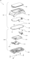
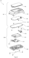
- FIG. 5 illustrates an exploded view of the head assembly, in accordance with an embodiment of the present disclosure.
- FIG. 6 illustrates another exploded view of the head assembly, in accordance with an embodiment of the present disclosure.
- FIG. 7 A illustrates a cross-sectional view of a display unit of the head assembly, in accordance with an embodiment of the present disclosure.
- FIG. 7 B and FIG. 7 C illustrate various views of a first housing assembly of the head assembly, in accordance with an embodiment of the present disclosure.
- FIG. 7 D illustrates an exploded view of the display unit, in accordance with an embodiment of the present disclosure.
- FIG. 8 illustrates a cross-sectional view of the head assembly in disassembled form, in accordance with an embodiment of the present disclosure.
- FIG. 9 illustrates a cross-sectional view of a region around an actuator of the head assembly, in accordance with an embodiment of the present disclosure.
- FIG. 10 illustrates a functional block diagram of the wearable physiological device, in accordance with an embodiment of the present disclosure.
- FIG. 11 illustrates assembling of a first housing assembly of the head assembly, in accordance with an embodiment of the present disclosure.
- FIG. 12 illustrates assembling of a second housing assembly of the head assembly, in accordance with an embodiment of the present disclosure.
- FIG. 13 illustrates assembling of the head assembly, in accordance with an embodiment of the present disclosure.
- FIG. 14 illustrates a perspective view of a docking station of a physiological apparatus, in accordance with an embodiment of the present disclosure.
- FIG. 15 illustrates an exploded view of the docking station, in accordance with an embodiment of the present disclosure.
- FIG. 16 illustrates a block diagram of the technical architecture of a computer, in accordance with some embodiments of the present disclosure.
- depiction of a given element or consideration or use of a particular element number in a particular figure or a reference thereto in corresponding descriptive material can encompass the same, an equivalent, or an analogous element or element number identified in another figure or descriptive material associated therewith.
- the use of “I” in a figure or associated text is understood to mean “and/or” unless otherwise indicated.
- the term “set” corresponds to or is defined as a non-empty finite organization of elements that mathematically exhibits a cardinality of at least one (e.g. a set as defined herein can correspond to a unit, singlet, or single element set, or a multiple element set), in accordance with known mathematical definitions.
- the recitation of a particular numerical value or value range herein is understood to include or be a recitation of an approximate numerical value or value range.
- the terms “comprising”, “including”, “having”, and the like do not exclude the presence of other features/elements/steps than those listed in an embodiment.
- a component or a module may be, but is not limited to being, a process running on a processor, a processor, an object, an executable, a thread of execution, a program, and/or a computer.
- an application running on a controller and the controller can be a component/module.
- One or more components/modules may reside within a process and/or thread of execution.
- the physiological device 20 is wearable on a user, e.g. worn on the wrist of the user, for monitoring of the user's physiological health and functions.
- the wearable physiological device 20 includes a head assembly 30 for performing various operations associated with said monitoring of the user's physiology.
- the head assembly 30 is configured for collecting and processing physiological signals or data from the user. The processed data may provide the user with various types of information, such as relating to the user's activity, sleep or stress condition.
- the head assembly 30 may be attachable to a separate retrieval platform where the user places a portion of the user's arm and/or fingers on the retrieval platform, further adding stability during monitoring of the user's physiological health.
- the head assembly 30 includes a first housing assembly 100 and a second housing assembly 200 removably coupled to the first housing assembly 100 .
- the first housing assembly 100 When worn on the user, the first housing assembly 100 is oriented above the second housing assembly 200 , wherein the second housing assembly 200 faces towards a skin surface of the user.
- the wearable physiological device 20 further includes a set of straps or bands 22 for strapping around or circumscribing the user's wrist.
- a set of straps or bands 22 for strapping around or circumscribing the user's wrist.
- the single continuous strap 22 attached to the head assembly 30 is wrappable around a portion of the user's wrist.
- the head assembly 30 includes a set of lugs 102 .
- the first housing assembly 100 includes a pair of lugs 102 on each side thereof. In each pair of lugs 102 , the lugs 102 are separated longitudinally away from each other, i.e. along the length of the user's arm.
- the wearable physiological device 20 includes two separate straps 22 removably attached to the lugs 102 . Specifically, each strap 22 has a proximal end 22 a and a distal end 22 b , the proximal end 22 a removably attached to the respective pairs of lugs 102 .
- the two separate straps 22 may be of similar/different lengths/widths, which when combined, circumscribe or enclose the user's wrist.
- one of the straps 22 includes a plurality of holes or recessed portions 24 .
- the other of the straps 22 includes a strap fastener 26 at the distal end 22 b thereof.
- the strap fastener 26 such as or including a protrusion or hook element, is engageable with one of the holes 24 for wearing and adapting of the physiological device 20 on the user's wrist.
- the plurality of holes 24 provides the user with flexibility of fitting the physiological device 20 with various wrist sizes of the user. It will be appreciated that the strap fastener 26 can be in various forms known to the skilled person.
- the strap fastener 26 is engaged or attached to a clasp 27 a with a latch pin 27 b through the strap fastener 26 .
- the latch pin 27 b may be separable from the strap fastener 26 for removing the clasp 27 a .
- the clasp 27 a may have a protrusion portion engageable with any one of the plurality of holes 24 of the opposite strap 22 for circumscribing or enclosing the user's wrist. Alternatively, these parts may be replaced with a standard wristwatch buckle 27 as shown in FIG. 2 A and FIG. 2 B .
- the holes 24 along one of the straps 22 have identical dimensions and shape.
- all the holes 24 along the strap 22 are circular with the same diameter.
- the holes 24 along one or both of the straps 22 are elongated, i.e. shaped in the form of slots 25 , and some of the slots 25 have different dimensions from the others.
- the slot 25 nearest the proximal end 22 a of the strap 22 is the longest and the slot 25 near the distal end 22 b of the strap 22 is the shortest, such that the lengths of the slots 25 decrease gradually from the proximal end 22 a to the distal end 22 b .
- each slot 25 is longer than the next slot 25 such that all the slots 25 have different lengths.
- some of the slots 25 have identical lengths, such as if the lengths decrease after every pair of consecutive slots 25 .
- the spaces between every pair of consecutive slots 25 may be identical, or the slots 25 may be randomly spaced apart.
- the slots 25 may be present in one or both of the straps 22 and the arrangement of the slots 25 enhances breathability when the physiological device 20 is worn on the user's wrist.
- the user may also prefer the slots 25 to be arranged in some pattern so as to more easily identify his/her personal physiological device 20 .
- the straps 22 may be imprinted or engraved with the user's signature/insignia 29 for easier identification.
- each strap 22 includes an extended portion 22 c disposed at or near the proximal end 22 a thereof.
- the extended portion 22 c may be chamfered or filleted to provide comfort to the physiological device 20 is worn.
- a gap 28 is formed between the extended portion 22 c and the head assembly 30 when the physiological device 20 is worn on the user's wrist.
- the extended portions 22 c may provide a snug fit to further lock and prevent the physiological device 20 from traversing along the length of the user's arm.
- the straps 22 When removed from the user's wrist, the straps 22 are unfastened and the physiological device 20 may be placed on a surface such as a table, the weight of the head assembly 30 weighs down and reduces the gaps 28 .
- the extended portions 22 c engages the head assembly 30 and prevents the head assembly 30 from contacting the surface, thereby providing greater stability when the physiological device 20 is placed on the surface. Additionally, the user may display and review the outputs from the physiological device 20 in a parallel eye level view.
- the straps 22 are removably attached to the lugs 102 . It will be appreciated that the attachment of the straps 22 to the lugs 102 is similar or analogous to that of wristwatch straps and lugs.
- one or both straps 22 includes a fastening pin 23 a at the proximal end 22 a thereof for engagement with the lugs 102 to thereby attach the straps 22 .
- One of the lugs 102 has a hole for receiving the fastening pin 23 a .
- the fastening pin 23 a is retractable, such as by spring-loading, so that the fastening pin 23 a can be easily unfastened from the hole to thereby detach the straps 22 . This allows for quick release, e.g. by clipping, latching, and/or snapping, for interchanging the straps 22 or replacing with personalized straps 22 .
- the first housing assembly 100 includes an engagement element 103 disposed at the lugs 102 , specifically between one or both pairs of the lugs 102 .
- One or both straps 22 includes an engagement element 23 b at the proximal end 22 a thereof for engagement with the respective engagement element 103 .
- the engagement elements 23 b disposed at the strap 22 and the engagement element 103 disposed at the first housing assembly 100 are matingly engageable with each other, similar to engagements between standard male and female fasteners known to the skilled person.
- the engagement elements 23 b and 103 have different designs and configurations such that the engagement element 23 b having a particular configuration uniquely matched and aligned to the engagement element 103 having a particular configuration.
- FIG. 3 A illustrates an example of the configurations of the engagement elements 23 b and 103 that are uniquely matched and aligned to each other. Accordingly, if the user has the physiological device 20 with particular configurations of the engagement elements 23 b and 103 , the user may replace the straps 22 with other straps 22 having the same engagement elements 23 b . This may encourage the user to purchase authentic straps 22 from the original manufacturer instead of getting imitation straps 22 which may not fit well, or at all, with the user's existing physiological device 20 .
- FIG. 3 B to FIG. 3 D illustrate other configurations of the engagement elements 103 . It will be appreciated that the straps 22 will have matching engagement elements 23 b for mating engagement with the engagement elements 103 . It will also be appreciated that use of such matching engagement elements 23 b and 103 may be on only one strap 22 or both straps 22 .
- the head assembly 30 includes the first housing assembly 100 and second housing assembly 200 removably coupled to each other.
- the first housing assembly 100 includes a first housing body 104 and the second housing assembly 200 includes a second housing body 202 , wherein the second housing body 202 is disposed below the first housing body 104 and removably coupled thereto.
- the first housing assembly 100 further includes a user interface assembly 106 attached or coupled to the first housing body 104 .
- the user interface assembly 106 includes a display unit 108 attached to or coupled to an upper portion of the first housing body 104 .
- the display unit 108 presents a screen 110 that provides a user interface for the user to control the physiological device 20 .
- the entire screen 110 is configured to receive control inputs from the user.
- the screen 110 is separated into a user interface area 112 and an inactive area 114 .
- the user interface area 112 is configured to receive control inputs from the user, while the inactive area 114 is non-responsive to user inputs.
- the display unit 108 may be configured for touch gesture operations by the user on the screen 110 .
- the user is able to perform various operations by touch gestures on the user interface area 112 of the screen 110 .
- the non-interactive area 114 may provide the user with relevant information in response to these touch operations.
- the user interface assembly 106 may further include a set of illumination elements 116 , such as light-emitting diodes (LEDs), for communicating visual signals, e.g. colour indications, to the user.
- the display unit 108 may be disposed with a filter portion for holding or laying different filter elements of different colours. The filter portion is thus cooperable with the illumination elements 116 to obtain different colour indications as desired by the user based on the choice of filter elements.
- the user interface assembly 106 includes an actuator or button 118 disposed on an exterior or peripheral portion of the first housing body 104 for user operation, such as to toggle among different functions, of the physiological device 20 .
- the different functions may by such as to provide the user with information on an activity e.g. distance and/or calorie count, sleep and/or stress condition that includes present or past state of mind.
- the second housing assembly 200 includes a set of physiological sensors 204 disposed on a lower portion of the second housing body 202 .
- the lower portion of the second housing body 202 refers to a boss portion 206 that protrudes below the second housing body 202 .
- the physiological sensors 204 are disposed on the boss portion 206 such that they are arranged to contact the user's skin (or at least being substantially proximate thereto) when the user is wearing the physiological device 20 .
- the physiological sensors 204 are configured for measuring physiological signals from the user wearing the physiological device 20 . These physiological signals include one or more of, but are not limited to, heart rate, blood pressure, photoplethysmogram (PPG) signals, and body temperature.
- PPG photoplethysmogram
- the physiological sensors 204 include one or more photodiode sensors for measuring PPG signals from the user's blood vessels.
- the second housing assembly 200 may further include an illumination element 208 , e.g. an LED, to complement the photodiode sensors.
- the user's skin is illuminated by the illumination element 208 and the photodiode sensors measure changes in light absorption.
- the physiological sensors 204 include one or more temperature sensors for measuring body temperature of the user. It will be appreciated that the physiological sensors 204 may include one or more different types to be used in combination with one another to measure various types of physiological signals and data from the user. The measured physiological signals and data are stored on a database residing within the physiological device 20 .
- the measured physiological signals and data may be streamed on-the-fly when connected to an electronic device separate from the physiological device 20 .
- This electronic device may be a computer, mobile phone, or some remote server having a database residing therein for receiving and storing the physiological signals and data.
- the second housing assembly 200 includes a set of electrical or charge contacts/pads 210 disposed on the lower portion of the second housing body 202 .
- the second housing assembly 200 includes a removable battery 212 disposed within the second housing body 202 , the battery 212 for powering the physiological device 20 .
- an old battery 212 may be removed from the second housing body 202 , and a new battery 212 simply inserted into the second housing body 202 .
- the new battery 212 is inserted into the second housing body 202 and soldered using standard soldering tools.
- the battery 212 may be chargeable, e.g.
- the electrical contacts 210 are connectable to an electrical supply for charging the battery 212 . It will be appreciated that the physiological device 20 may be powered directly from the electrical supply via the electrical contacts 210 in the absence of the battery 212 , such as when the battery 212 is damaged and removed from the second housing body 202 .
- the first housing assembly 100 and second housing assembly 200 are removably coupled together via a set of fasteners 32 .
- the fasteners 32 may be screws or bolts that can be removed by the user with common household tools such as a screwdriver. Accordingly, the first housing assembly 100 and second housing assembly 200 can be easily disassembled and reassembled by the user.
- the first housing assembly 100 includes a first circuit assembly 120 removably coupled to the first housing body 104 .
- the second housing assembly 200 includes a second circuit assembly 214 removably coupled to the second housing body 202 .
- Each of the first circuit assembly 120 and second circuit assembly 214 includes a printed circuit board (PCB) that supports and electrically connects various electrical/electronic components, as will be readily understood by the skilled person.
- PCB printed circuit board
- the first circuit assembly 120 is coupled to the first housing body 104 and is disposed below the user interface assembly 106 .
- the user interface assembly 106 is also communicatively connected to the first circuit assembly 120 , such that operations performed by the user with the user interface assembly 106 , e.g. the user interface area 112 and actuator 118 , are communicated to the first circuit assembly 120 for processing.
- the first circuit assembly 120 is removably coupled to the first housing body 104 with a set of fasteners 122 , e.g. screws, allowing the user to easily disassemble and reassemble the first circuit assembly 120 .
- the second circuit assembly 214 is coupled to the second housing body 202 .
- the second circuit assembly 214 is removably coupled, e.g. by an attachment or latching mechanism known to the skilled person, to an internal surface of the second housing body 202 .
- the second circuit assembly 214 includes the physiological sensors 204 , illumination element 208 , and removable battery 212 .
- the physiological sensors 204 are disposed on one side of the second circuit assembly 214 and the battery 212 is disposed on the reverse side of the second circuit assembly 214 .
- the second circuit assembly 214 includes a flexible connector 216 communicatively connecting the second circuit assembly 214 to the first circuit assembly 120 .
- the flexible connector 216 is a flexible printed circuit (FPC) that enables electronic communication, including data and electricity, between the first circuit assembly 120 and second circuit assembly 214 .
- FPC flexible printed circuit
- physiological signals measured by the physiological sensors 204 are communicable from the second circuit assembly 214 to the first circuit assembly 120 via the flexible connector 216 , and subsequently processed and displayed to the user on the display unit 108 .
- Electricity from the battery 212 is also conducted from the electrical contacts 210 to the second circuit assembly 214 and subsequently to the first circuit assembly 120 .
- the second housing assembly 200 includes a haptic device 218 and optionally an accelerometer coupled to the second housing body 202 .
- the haptic device 218 includes a haptic motor that provides kinesthetic communication to the user, such as by applying forces, vibrations, and/or motions to the user when the user is wearing the physiological device 20 .
- the kinesthetic communication may be in the form of haptic feedback, e.g. force or vibrational feedback, to the user in response to various results derived from the physiological signals.
- the haptic device 218 may be removably coupled to the second housing body 202 with a set of fasteners 220 , e.g. screws, allowing the user to easily disassemble and reassemble the haptic device 218 .
- the wearable physiological device 20 includes an intermediate support 34 disposed between the first housing assembly 100 and second housing assembly 200 .
- the intermediate support 34 is arranged to surround a periphery of the first housing body 104 and second housing body 202 for inhibiting/reducing liquid ingress or seepage, into the first housing assembly 100 and second housing assembly 200 , thereby providing a water resistance feature to the physiological device 20 .
- the intermediate support 34 includes a sealing element 36 , disposed around the periphery of the intermediate support 34 , which seals the space between the first housing assembly 100 and second housing assembly 200 upon assembling and merging of the first housing assembly 100 and second housing assembly 200 .
- the first housing assembly 100 includes a flexible connector 124 which is a FPC that enables electronic communication between the first circuit assembly 120 and display unit 108 .
- a flexible connector 124 is a FPC that enables electronic communication between the first circuit assembly 120 and display unit 108 .
- one end of the flexible connector 124 is connected to the first circuit assembly 120 and another end of the flexible connector 124 is connected to the display unit 108 .
- the flexible connector 124 includes a set of touch controllers or touch control modules/components 126 for communicating touch gestures made on the display unit 108 to the first circuit assembly 120 .
- the illumination elements 116 are disposed on the display unit 108 for providing visual indications to the user. In another embodiment, the illumination elements 116 are disposed on the first circuit assembly 120 .
- the display unit 108 includes one or more apertures aligned with the illumination elements 116 to allow light from the illumination elements 116 to pass through.
- the first housing body 104 includes one or more slots or receptacles 127 a to receive a diffuser 127 b .
- the slot 127 a is aligned with the illumination elements 116 such that the diffuser 127 b is arranged to evenly distribute light from the illumination elements 116 .
- the diffuser 127 b may evenly distribute heat generated by the illumination elements 116 .
- the display unit 108 includes various components in a layered arrangement, such that these components/layers can be assembled by stacking up in a systematic or modular manner.
- the components/layers may be assembled together by adhesive/bonding materials as will be apparent to the skilled person.
- the display unit 108 includes a cover layer 108 a to protect the other internal layers of the display unit 108 .
- the user interfaces with the physiological device 20 via the display unit 108 , e.g. by touch gestures on the cover layer 108 a .
- the cover layer 108 may be made of a glass material that is scratch-resistant and shatterproof.
- the cover layer 108 may be made of other materials, such as a plastic or a composite material, as will be readily known to the skilled person.
- the display unit 108 includes a tint layer/panel 108 b to mask away glare, such as sunlight glare when the physiological device 20 is used outdoors.
- the display unit 108 includes a mask or logo layer/panel 108 c for providing a fixed or predefined space for display visualization.
- the fixed or predefined space includes a boundary space corresponding to the inactive area 114 as shown in FIG. 4 B .
- the display unit 108 includes an ITO (indium tin oxide) layer/panel 108 d for output display based on information received from the first circuit assembly 120 .
- ITO indium tin oxide
- the display unit 108 includes an OLED (organic light-emitting diode) layer/panel 108 e which is an emissive electroluminescent layer that emits light in response to an electric current.
- the layer/panel 108 e may alternatively be of another type of light-emitting layer, such as LED or Liquid Crystal Display (LCD).
- the layer/panel 108 e may be of a flat or curved shape.
- the display unit 108 includes a support layer 108 f for combining each of the other layers 108 a to 108 e to form into the display unit 108 .
- the support layer 108 f has an adhesive material for combining the other layers 108 a to 108 e together.
- the support layer 108 f also functions as a sealing element to prevent liquid or water ingress/seepage into the first housing assembly 100 via the display unit 108 .
- the display unit 108 may be modified to be without one or more of the layers 108 a to 108 f , and that the display unit 108 may similarly be modified to include additional layers or panels known to the skilled person.
- the support layer 108 f has an adhesive material for attaching the display unit 108 to the first housing body 104 .
- the display unit 108 is removably coupled to the first housing body 104 with an attachment or latching mechanism known to the skilled person, allowing the user to easily disassemble and reassemble the display unit 108 .
- the head assembly 30 includes various sealing elements for preventing liquid or water ingress/seepage into the head assembly 30 .
- the second housing assembly 200 includes a sensor protective cover 222 for the physiological sensors 204 .
- the sensor protective cover 222 protects and seals the physiological sensors 204 from water ingress.
- the sensor protective cover 222 includes a transparent portion so that light can still be transmitted from the illumination element 208 to the skin and that physiological signals can be effectively measured.
- the transparent portion may have a magnifying effect to improve the quality of measurements.
- the magnifying effect may be achieved by adding one or more other optical elements, e.g. objective lens.
- the second housing assembly 200 may include a sealing cover 224 for the electrical contacts 210 .
- the sealing cover 224 may be removed by the user when the battery 212 needs to be charged, and replace the sealing cover 224 during use of the physiological device 20 so as to maintain its water resistance.
- the first housing assembly 100 includes a sealing element 128 for the actuator 118 .
- a sealing element 128 for the actuator 118 . Referring to FIG. 9 illustrating a cross-sectional view of the region around the actuator 118 , the sealing element 128 surrounding an inner actuating portion 118 a .
- the inner actuating portion 118 a is connected or integrally joined to an outer actuating portion 118 b which is exposed for the user to operate.
- the sealing element 128 may be or includes an O-ring or toric joint which seals the inner actuating portion 118 a to prevent liquid/water ingress/seepage into the first housing assembly 100 .
- the first housing assembly 100 includes a set of biasing mechanisms 130 , e.g. compression springs, for biasing the actuator 118 back to the unactuated state after actuation by the user.
- biasing mechanisms 130 e.g. compression springs
- the inner actuating portion 118 a actuates and contacts a switch module or component 132 of the first circuit assembly 120 , thereby performing an operation or function on the wearable device 20 .
- the biasing mechanisms 130 return the actuator 118 from the actuated state to the unactuated state.
- the inner actuating portion 118 a is assembled into the first housing body 104 through a hole thereof and with appropriate engineering tolerance.
- the engineering tolerance is determined to align the inner actuating portion 118 a with the hole and to improve axial stability of the actuator 118 .
- the first housing assembly 100 includes a clip mechanism 134 for clipping the inner actuating portion 118 a to prevent removal of the actuator 118 from the first housing assembly 100 .
- the clip mechanism 134 may be separable from the first housing body 104 for removing the actuator 118 , such as for replacing a damaged actuator 118 .
- the first housing assembly 100 includes a data communication module or component 136 communicatively connected to the first circuit assembly 120 .
- the wearable physiological device 20 is communicable with an electronic device 50 via the data communication module 136 .
- the electronic device 50 may be a mobile device, such as mobile phone, smartphone, personal digital assistant (PDA), tablet, laptop, or computer.
- the head assembly 30 includes a communication port for connecting to a communication cable which is in turn connectable to the electronic device 50 , such as a USB (Universal Serial Bus) port for receiving a USB cable.
- a communication cable which is in turn connectable to the electronic device 50
- USB Universal Serial Bus
- the electronic device 50 is a remote server that is a physical or cloud data processing system and includes computers, laptops, mini-computers, mainframe computers, any non-transient and tangible machines that can execute a machine-readable code, cloud-based servers, distributed server networks, and a network of computer systems.
- the communication between the physiological device 20 and electronic device 50 via the data communication module 136 may occur across a communication network, such as by wireless communication protocols, as will be readily understood by the skilled person.
- the communication network may be a short range, such as Wi-Fi, Bluetooth Low Energy (BLE), or Near Field Communication (NFC).
- the communication network may be long range, such as Local Area Network (LAN), Wireless Area Network (WAN), telecommunication network, cellular network, satellite network, or LoRa WAN (Long Range WAN).
- the physiological device 20 is wearable on the user's wrist for monitoring of the user's physiological health.
- the physiological sensors 204 measure physiological signals from the user's blood vessels and communicate the physiological signals to the second circuit assembly 214 and subsequently to the first circuit assembly 120 for processing.
- Each of the first circuit assembly 120 and second circuit assembly 214 includes a computer processor or microprocessor for performing said processing.
- the processed data may provide the user with various types of information, such as relating to the user's activity, sleep or stress condition, and the information is presented to the user via the display unit 108 and illumination elements 116 .
- the screen 110 may display one or more icons for presenting information to the user. The icons may relate to different situations, such as when the user is in a stress state, normal state, or when no data is obtained.
- the illumination elements 116 may provide visual indications to the user, such as of the user's stress condition or state. For example, if the illumination elements 116 illuminated in purple colour may represent an abnormal stress condition, while green colour may represent a normal condition. Other colours may indicate other information, such as lack of or inadequate physiological data from the sensors 204 , or failure/malfunctioning of the sensors 204 . As mentioned above, the illumination elements 106 may be replaced by the user with that of other colours.
- the information may also be communicated from the physiological device 20 to the electronic device 50 , such as for keeping data records of the user's activity/sleep/stress history.
- the head assembly 30 may be modified to include additional components, such as additional alert devices (sound and/or haptic).
- additional alert devices sound and/or haptic.
- Some other components may include, but are not limited to, accelerometers, gyroscopes, and magnetometers.
- the head assembly 30 is formed by assembling various parts or components together. Some of these components are removably coupled so that they can be replaced by the user. For example, the first housing assembly 100 and second housing assembly 200 are removably coupled together.
- FIG. 11 illustrates the assembling of the first housing assembly 100 .
- the first housing body 104 may be formed by standard manufacturing technologies known to the skilled person.
- the first housing body 104 may be formed as a single integral body or from a plurality of structures/bodies joined together.
- the user interface assembly 106 is coupled to the first housing body 104 .
- the display unit 108 and actuator 118 are coupled to the first housing body 104 .
- the display unit 108 is coupled by an adhesive.
- the display unit 108 is removably coupled by an attachment or latching mechanism.
- the first circuit assembly 120 is removably coupled to the first housing body 104 , such as with a set of fasteners or screws 122 . Accordingly, various components of the first housing assembly 100 are easily assembled together in a stacked or layered arrangement with minimal effort. It will be appreciated that disassembly can also be done easily in a reverse manner. For example, the first circuit assembly 120 may have to be removed/decoupled first before removing/decoupling the display unit 108 .
- FIG. 12 illustrates the assembling of the second housing assembly 200 .
- the second housing body 202 may be formed by standard manufacturing technologies known to the skilled person.
- the second housing body 202 may be formed as a single integral body or from a plurality of structures/bodies joined together.
- the second circuit assembly 214 is removably coupled to the second housing body 202 , such as with an attachment or latching mechanism.
- the haptic device 218 is also removably coupled to the second housing body 202 , such as with fasteners/screws.
- the battery 212 is removably coupled to the second housing body 202 by disposing on the second circuit assembly 214 .
- a vibration absorber 226 is removably coupled to the second housing body 202 , such as with fasteners/screws.
- the vibration absorber 226 is positioned to overlay the haptic device 218 so as to absorb or reduce vibrations caused by motion of the haptic device 218 .
- various components of the second housing assembly 200 are easily assembled together in a stacked or layered arrangement with minimal effort. It will be appreciated that disassembly can also be done easily in a reverse manner.
- the battery 212 may have to be removed/decoupled first before removing/decoupling the second circuit assembly 214 .
- FIG. 13 illustrates the assembling of the first housing assembly 100 and second housing assembly 200 together. Specifically, the first housing assembly 100 and second housing assembly 200 are removably coupled together via a set of fasteners or screws. Upon said coupling, the flexible connector 216 connects the second circuit assembly 214 to the first circuit assembly 120 for communication therebetween.
- connections among components coupled to the first circuit assembly 120 are coupled with the use of spring fingers instead of cables.
- the first housing assembly 100 and second housing assembly 200 are coupled together, there is only the flexible connector 216 to connect between them. This flexible connector 216 is easy to connect and does not require special tools.
- the first housing assembly 100 and second housing assembly 200 are easily assembled together in a stacked or layered arrangement with minimal effort.
- Various components of the head assembly 30 can thus be disassembled and reassembled by the user. These components can be easily replaced by the user if they become damaged or are worn out after prolonged use.
- components in a constant active state e.g. physiological sensors 204 and battery 212 , have shorter lifespans than other components, and their operational performances are more easily affected by time.
- the user will not be necessary for the user to replace the entire physiological device 20 or head assembly 30 if only one or some components are damaged, thus reducing their expenditure on repairing the physiological device 20 .
- the user is given more control of the physiological device 20 and this helps to extend the lifespan of the physiological device 20 .
- the wearable physiological device 20 is customizable in design and the user can easily disassemble and reassemble the physiological device 20 , possibly with repaired/upgraded components.
- a physiological apparatus including the wearable physiological device 20 and a docking station 300 for docking the physiological device 20 thereto in one orientation, as illustrated in FIG. 14 .
- the physiological device 20 is dockable to the docking station 300 for charging of the physiological device 20 .
- the physiological apparatus provides another platform or way to review data from the physiological device 20 .
- the docking station 300 includes a docking assembly 302 and a set of electrical connectors 304 disposed on the docking assembly 302 .
- the docking assembly 302 includes a receptacle portion 306 for receiving the boss portion 206 of the physiological device 20 .
- the boss portion 206 refers to the lower portion of the second housing body 202 .
- the receptacle portion 306 is substantially congruent to the boss portion 206 , such that the boss portion 206 is able to fit snugly within the receptacle portion 306 upon docking of the physiological device 20 to the docking station 300 . It will be appreciated that the boss portion 206 and receptacle portion 306 have appropriate engineering tolerance to achieve the desired fit.
- the electrical connectors 304 are automatically aligned to the electrical contacts 210 disposed on the boss portion 206 .
- the boss portion 206 and receptacle portion 306 have a round shape.
- Various mechanisms, such as a detent, may be implemented to resist or arrest the rotation of the boss portion 206 around the receptacle portion 306 .
- there is only one orientation wherein the receptacle portion 306 can receive the boss portion 206 thereby achieving alignment between the electrical connectors 304 and electrical contacts 210 .
- the boss portion 206 and receptacle portion 306 have a polygonal shape. Specifically, the polygonal shape is of an irregular polygon, such that there is only one orientation wherein the receptacle portion 306 can receive the boss portion 206 .
- the docking assembly 302 includes a first docking body 308 and a second docking body 310 removably coupled together via a set of fasteners 312 .
- the fasteners 312 may be screws or bolts that can be removed by the user with common household tools such as a screwdriver. Accordingly, the first docking body 308 and second docking body 310 can be easily disassembled and reassembled by the user.
- each fastener 312 may have snap protrusions attachable to snap receivers disposed on the first docking body 308 and second docking body 310 .
- the docking station 300 includes a docking circuit assembly 314 removably coupled to the first docking body 308 and/or second docking body 310 .
- the docking circuit assembly 314 includes a PCB.
- the docking circuit assembly 314 is electrically connected to the electrical connectors 304 and an electrical cable 316 leading to an electrical/communication port.
- the electrical cable 316 may be a USB cable.
- the electrical connectors 304 may be in the form of pogo pins.
- the electrical connectors 304 Upon said docking and connection to a power supply, the electrical connectors 304 are connected to the electrical contacts 210 , and electricity is conducted from the power supply to the electrical connectors 304 and electrical contacts 210 for charging the battery 212 of the physiological device 20 .
- the user may alternatively connect an external electrical/communication cable between the electrical/communication port and the physiological device 20 , such that the physiological device 20 need not remain docked and the user can still use the physiological device 20 during charging.
- the docking station 300 includes a set of magnets 318 coupled to the first docking body 308 .
- the magnets 318 are arranged for attracting the boss portion 206 into the receptacle portion 306 and for automatically aligning the electrical connectors 304 to the electrical contacts 210 .
- the boss portion 206 or at least an exterior surface thereof, may be made of a magnetic or metallic material to achieve magnetic attraction with the magnets 318 .
- the head assembly 30 may include some form of magnetic shielding to protect sensitive components thereof, as will be readily understood by the skilled person.
- the docking station 300 includes a set of stands 320 for elevating the docking assembly 302 and for reducing tension in the straps 22 of the physiological device 20 upon said docking. For example, when the physiological device 20 is docked to the docking station 300 with an elevated docking assembly 302 , the straps 22 are allowed to dangle in a relaxed state, thereby reducing tension in the straps 22 .
- the stands 320 may be rubberized for stability when the docking station 300 is placed on a surface.
- the docking station 300 may be made of a lightweight material so that it is portable for use at various places.
- FIG. 16 is a block diagram illustrating a technical architecture of a computer 400 in accordance with embodiments of the present disclosure.
- the computer 400 includes a processor/central processing unit (CPU) 402 , memory devices 404 , a database 406 , a data communication module 408 , and a physiological data module 410 .
- CPU central processing unit
- the processor 402 executes instructions, codes, computer programs, and/or scripts which it accesses from the memory devices 404 .
- the processor 402 includes suitable logic, circuitry, and/or interfaces to execute such operations or steps.
- Some non-limiting examples of the processor 402 include an application-specific integrated circuit (ASIC) processor, a reduced instruction set computing (RISC) processor, a complex instruction set computing (CISC) processor, a field-programmable gate array (FPGA), and the like. While only one processor 402 is shown, multiple processors 402 may be present. Thus, while instructions may be discussed as executed by a processor 402 , the instructions may be executed simultaneously, serially, or otherwise executed by one or multiple processors 402 (e.g. in a multi-core configuration).
- ASIC application-specific integrated circuit
- RISC reduced instruction set computing
- CISC complex instruction set computing
- FPGA field-programmable gate array
- the memory devices 404 may comprise storage devices (such as flash memory, disk drives, or memory cards), read-only memory (ROM), and random-access memory (RAM).
- the memory devices 404 store non-transitory instructions operative by the processor 402 .
- the memory devices 404 may be referred to as computer-readable storage media and/or non-transitory computer-readable media.
- Non-transitory computer-readable media include all computer-readable media, with the sole exception being a transitory propagating signal per se.
- the database 406 is any computer-operated hardware suitable for storing data.
- the database 406 may include multiple storage units such as hard disks and/or solid-state disks in a Redundant Array of Independent Disks (RAID) configuration.
- the database 406 may include, but is not limited to, a storage area network (SAN) and/or a network attached storage (NAS) system.
- the data communication module 408 is configured for communication with other computers 400 .
- the physiological data module 410 is configured to measure and process the physiological data. Various algorithms may be implemented in the physiological data module 410 for performing various assessment and/or diagnosis using the physiological data to generate useful information for the user.
Landscapes
- Health & Medical Sciences (AREA)
- Life Sciences & Earth Sciences (AREA)
- Engineering & Computer Science (AREA)
- Physics & Mathematics (AREA)
- Biophysics (AREA)
- General Health & Medical Sciences (AREA)
- Surgery (AREA)
- Public Health (AREA)
- Medical Informatics (AREA)
- Molecular Biology (AREA)
- Biomedical Technology (AREA)
- Animal Behavior & Ethology (AREA)
- Pathology (AREA)
- Heart & Thoracic Surgery (AREA)
- Veterinary Medicine (AREA)
- Cardiology (AREA)
- Physiology (AREA)
- General Physics & Mathematics (AREA)
- Theoretical Computer Science (AREA)
- Human Computer Interaction (AREA)
- General Engineering & Computer Science (AREA)
- Measuring And Recording Apparatus For Diagnosis (AREA)
Abstract
Description
Claims (20)
Applications Claiming Priority (3)
| Application Number | Priority Date | Filing Date | Title |
|---|---|---|---|
| SG10201801744T | 2018-03-02 | ||
| SG10201801744T | 2018-03-02 | ||
| PCT/SG2019/050112 WO2019168475A1 (en) | 2018-03-02 | 2019-02-28 | Wearable physiological device and apparatus |
Publications (2)
| Publication Number | Publication Date |
|---|---|
| US20210106278A1 US20210106278A1 (en) | 2021-04-15 |
| US12070331B2 true US12070331B2 (en) | 2024-08-27 |
Family
ID=67808802
Family Applications (1)
| Application Number | Title | Priority Date | Filing Date |
|---|---|---|---|
| US16/977,361 Active 2041-12-25 US12070331B2 (en) | 2018-03-02 | 2019-02-28 | Wearable physiological device and apparatus |
Country Status (7)
| Country | Link |
|---|---|
| US (1) | US12070331B2 (en) |
| EP (1) | EP3758594A4 (en) |
| JP (1) | JP7344214B2 (en) |
| CN (1) | CN112074229A (en) |
| AU (1) | AU2019227071A1 (en) |
| SG (1) | SG11202008457SA (en) |
| WO (1) | WO2019168475A1 (en) |
Families Citing this family (16)
| Publication number | Priority date | Publication date | Assignee | Title |
|---|---|---|---|---|
| JP7102335B2 (en) * | 2018-12-27 | 2022-07-19 | オムロンヘルスケア株式会社 | Blood pressure measuring device |
| GB2591434B (en) | 2019-10-29 | 2022-04-20 | Prevayl Innovations Ltd | Wearable article, textile article and method |
| CN110841288B (en) * | 2019-11-07 | 2022-02-25 | 腾讯科技(深圳)有限公司 | Prompt identifier eliminating method, device, terminal and storage medium |
| CN110928178A (en) * | 2019-12-31 | 2020-03-27 | 歌尔科技有限公司 | Wearable equipment |
| GB2593949B (en) | 2020-01-21 | 2023-04-26 | Prevayl Innovations Ltd | Electronics module for a wearable article |
| US12036041B2 (en) | 2020-02-19 | 2024-07-16 | Prevayl Innovations Limited | Wearable assembly comprising a wearable article and an electronics module |
| GB2590988B (en) | 2020-02-19 | 2021-12-29 | Prevayl Innovations Ltd | Electronics module for a wearable article |
| US11329035B2 (en) * | 2020-04-16 | 2022-05-10 | International Business Machines Corporation | Tetherless chip module |
| CA3198477A1 (en) | 2020-10-16 | 2022-04-21 | Whoop, Inc. | Physiological monitoring systems |
| US11925473B2 (en) | 2020-12-10 | 2024-03-12 | Whoop, Inc. | Detecting sleep intention |
| JP2024500724A (en) * | 2020-12-16 | 2024-01-10 | イーエヌデータクト ゲーエムベーハー | Measuring device and corresponding method for non-invasively detecting intracranial pressure in a patient |
| CN113156802A (en) * | 2021-02-03 | 2021-07-23 | 维沃移动通信有限公司 | Wearable device |
| CN115886407B (en) * | 2021-08-19 | 2026-03-17 | 明门瑞士股份有限公司 | Female buckle and fastener |
| US20230270382A1 (en) * | 2022-02-25 | 2023-08-31 | Alec Linarte | Wearable activity tracking and biometric monitoring device |
| WO2023234862A1 (en) * | 2022-05-30 | 2023-12-07 | Nitto Denko Corporation | Wearable physiological device |
| US20240306992A1 (en) * | 2023-03-16 | 2024-09-19 | Know Labs, Inc. | Wearable health monitoring device |
Citations (17)
| Publication number | Priority date | Publication date | Assignee | Title |
|---|---|---|---|---|
| US7618260B2 (en) | 2004-02-27 | 2009-11-17 | Daniel Simon R | Wearable modular interface strap |
| WO2011094876A1 (en) | 2010-02-05 | 2011-08-11 | Solianis Holding Ag | Wearable sensor device with battery |
| US20110221688A1 (en) * | 2010-03-15 | 2011-09-15 | Lg Electronics Inc. | Watch type mobile terminal |
| US8613544B2 (en) * | 2009-09-01 | 2013-12-24 | Casio Computer Co., Ltd. | Band, wristwatch with the band and method of making the band |
| US20140107493A1 (en) * | 2012-06-22 | 2014-04-17 | Fitbit, Inc. | Portable Biometric Monitoring Devices and Methods of Operating Same |
| US20140180019A1 (en) * | 2010-09-30 | 2014-06-26 | Fitbit, Inc. | Wearable biometric monitoring devices, interchangeable accessories and integrated fastenings to permit wear |
| US20140247137A1 (en) * | 2013-03-04 | 2014-09-04 | Hello Inc. | Base charging station for monitoring device |
| US20150105221A1 (en) * | 2013-10-14 | 2015-04-16 | Garmin Switzerland Gmbh | Fitness monitor |
| US20150265214A1 (en) | 2014-03-24 | 2015-09-24 | Samsung Electronics Co., Ltd. | Adjustable sensor support structure for optimizing skin contact |
| WO2015168590A1 (en) | 2014-05-01 | 2015-11-05 | Neumitra Inc. | Wearable electronics |
| US20150340891A1 (en) * | 2013-12-31 | 2015-11-26 | Samsung Electronics Co., Ltd. | Battery Charger |
| EP3009069A2 (en) | 2014-10-16 | 2016-04-20 | Samsung Electronics Co., Ltd. | Wearable sensor to monitor biosignal and method to monitor biosignal using wearable device |
| US9685802B1 (en) * | 2015-04-29 | 2017-06-20 | Verily Life Sciences, LLC | Detection of accessory presence and orientation |
| US9711060B1 (en) | 2014-07-14 | 2017-07-18 | Senstream, Inc. | Biometric sensor ring for continuous wear mobile data applications |
| WO2017136383A1 (en) | 2016-02-02 | 2017-08-10 | Maintool SAS | Flexible electronic strip and its method for manufacture |
| US20180220972A1 (en) * | 2017-02-03 | 2018-08-09 | Samsung Electronics Co., Ltd. | Electronic device capable of measuring biometric information |
| US20190388028A1 (en) * | 2016-12-07 | 2019-12-26 | Lg Electronics Inc. | Watch type terminal |
Family Cites Families (5)
| Publication number | Priority date | Publication date | Assignee | Title |
|---|---|---|---|---|
| CN103919536B (en) * | 2013-01-15 | 2018-05-01 | 飞比特公司 | Portable biometric monitoring device and method of operation thereof |
| CN103720461B (en) * | 2014-01-07 | 2016-03-02 | 北京微心百源科技发展有限公司 | Wearable type multi-parameter physiological index collector |
| MX394603B (en) * | 2014-11-03 | 2025-03-21 | Beijing Shunyuan Kaihua Tech Limited | SYSTEMS AND METHODS FOR OPTICAL ISOLATION IN THE MEASUREMENT OF PHYSIOLOGICAL PARAMETERS |
| KR20160115650A (en) * | 2015-03-25 | 2016-10-06 | 삼성전자주식회사 | Wearable electronic device |
| EP3277179B1 (en) * | 2015-03-31 | 2019-02-27 | Koninklijke Philips N.V. | Bodily-worn respiratory effort sensing apparatus providing automatic power up and initiation of data recording on a respiratory monitoring recording device |
-
2019
- 2019-02-28 JP JP2020545678A patent/JP7344214B2/en active Active
- 2019-02-28 EP EP19760011.7A patent/EP3758594A4/en not_active Withdrawn
- 2019-02-28 AU AU2019227071A patent/AU2019227071A1/en not_active Abandoned
- 2019-02-28 SG SG11202008457SA patent/SG11202008457SA/en unknown
- 2019-02-28 CN CN201980029853.9A patent/CN112074229A/en active Pending
- 2019-02-28 US US16/977,361 patent/US12070331B2/en active Active
- 2019-02-28 WO PCT/SG2019/050112 patent/WO2019168475A1/en not_active Ceased
Patent Citations (17)
| Publication number | Priority date | Publication date | Assignee | Title |
|---|---|---|---|---|
| US7618260B2 (en) | 2004-02-27 | 2009-11-17 | Daniel Simon R | Wearable modular interface strap |
| US8613544B2 (en) * | 2009-09-01 | 2013-12-24 | Casio Computer Co., Ltd. | Band, wristwatch with the band and method of making the band |
| WO2011094876A1 (en) | 2010-02-05 | 2011-08-11 | Solianis Holding Ag | Wearable sensor device with battery |
| US20110221688A1 (en) * | 2010-03-15 | 2011-09-15 | Lg Electronics Inc. | Watch type mobile terminal |
| US20140180019A1 (en) * | 2010-09-30 | 2014-06-26 | Fitbit, Inc. | Wearable biometric monitoring devices, interchangeable accessories and integrated fastenings to permit wear |
| US20140107493A1 (en) * | 2012-06-22 | 2014-04-17 | Fitbit, Inc. | Portable Biometric Monitoring Devices and Methods of Operating Same |
| US20140247137A1 (en) * | 2013-03-04 | 2014-09-04 | Hello Inc. | Base charging station for monitoring device |
| US20150105221A1 (en) * | 2013-10-14 | 2015-04-16 | Garmin Switzerland Gmbh | Fitness monitor |
| US20150340891A1 (en) * | 2013-12-31 | 2015-11-26 | Samsung Electronics Co., Ltd. | Battery Charger |
| US20150265214A1 (en) | 2014-03-24 | 2015-09-24 | Samsung Electronics Co., Ltd. | Adjustable sensor support structure for optimizing skin contact |
| WO2015168590A1 (en) | 2014-05-01 | 2015-11-05 | Neumitra Inc. | Wearable electronics |
| US9711060B1 (en) | 2014-07-14 | 2017-07-18 | Senstream, Inc. | Biometric sensor ring for continuous wear mobile data applications |
| EP3009069A2 (en) | 2014-10-16 | 2016-04-20 | Samsung Electronics Co., Ltd. | Wearable sensor to monitor biosignal and method to monitor biosignal using wearable device |
| US9685802B1 (en) * | 2015-04-29 | 2017-06-20 | Verily Life Sciences, LLC | Detection of accessory presence and orientation |
| WO2017136383A1 (en) | 2016-02-02 | 2017-08-10 | Maintool SAS | Flexible electronic strip and its method for manufacture |
| US20190388028A1 (en) * | 2016-12-07 | 2019-12-26 | Lg Electronics Inc. | Watch type terminal |
| US20180220972A1 (en) * | 2017-02-03 | 2018-08-09 | Samsung Electronics Co., Ltd. | Electronic device capable of measuring biometric information |
Non-Patent Citations (2)
| Title |
|---|
| International Search Report for Application No. PCT/SG2019/050112 mailed May 23, 2019, 3 pages. |
| Search Report for European Application No. 19760011 dated Oct. 29, 2021. 2 pgs. |
Also Published As
| Publication number | Publication date |
|---|---|
| EP3758594A4 (en) | 2021-12-08 |
| US20210106278A1 (en) | 2021-04-15 |
| AU2019227071A1 (en) | 2020-09-24 |
| CN112074229A (en) | 2020-12-11 |
| SG11202008457SA (en) | 2020-09-29 |
| EP3758594A1 (en) | 2021-01-06 |
| JP2021514770A (en) | 2021-06-17 |
| WO2019168475A1 (en) | 2019-09-06 |
| JP7344214B2 (en) | 2023-09-13 |
Similar Documents
| Publication | Publication Date | Title |
|---|---|---|
| US12070331B2 (en) | Wearable physiological device and apparatus | |
| KR102295668B1 (en) | Support structure including conductive paths and electronic device having the same | |
| US10277266B1 (en) | Mobile device case and methods of making and using same | |
| EP3108472B1 (en) | Curved body and wearable device therewith | |
| CN107507935B (en) | Strap and electronic device including the same | |
| US20140141838A1 (en) | Mobile device case with interchangeable display | |
| KR20180109444A (en) | Pcb including connector and grounds with different potentials and electronic device having the same | |
| CN210694032U (en) | an electronic device | |
| KR20150019502A (en) | A diaplay device | |
| US20130229359A1 (en) | Electronic apparatus | |
| US20160073882A1 (en) | Wearable electronic device | |
| CN108353097A (en) | Modular wearable smartband with replaceable functional units | |
| CN205318113U (en) | Smart watch | |
| CN106030447B (en) | Product Demonstration Fixtures for Portable Electronics | |
| TW201715340A (en) | Wearable electronic device | |
| CN203838675U (en) | Flexible display device | |
| US20160197635A1 (en) | System, apparatus and method for generic electronic device power module and case formation | |
| WO2023234862A1 (en) | Wearable physiological device | |
| TWI323862B (en) | Flat display apparatus and flexible housing | |
| CN214479685U (en) | charging stand | |
| CN204945630U (en) | Liftable intelligent watch | |
| CN114583770B (en) | Charging station | |
| KR101625099B1 (en) | Computer with wireless recharging of mobile device | |
| US9578146B2 (en) | Electronic assembly and electronic apparatus | |
| CN212814799U (en) | Double-temperature detection's conversation bracelet |
Legal Events
| Date | Code | Title | Description |
|---|---|---|---|
| FEPP | Fee payment procedure |
Free format text: ENTITY STATUS SET TO UNDISCOUNTED (ORIGINAL EVENT CODE: BIG.); ENTITY STATUS OF PATENT OWNER: LARGE ENTITY |
|
| AS | Assignment |
Owner name: NITTO DENKO CORPORATION, JAPAN Free format text: ASSIGNMENT OF ASSIGNORS INTEREST;ASSIGNORS:QUINN, ALAN;GEHRIG, COLIN;GRECO, DENIS;AND OTHERS;SIGNING DATES FROM 20190405 TO 20190412;REEL/FRAME:053817/0818 |
|
| STPP | Information on status: patent application and granting procedure in general |
Free format text: APPLICATION DISPATCHED FROM PREEXAM, NOT YET DOCKETED |
|
| STPP | Information on status: patent application and granting procedure in general |
Free format text: DOCKETED NEW CASE - READY FOR EXAMINATION |
|
| STPP | Information on status: patent application and granting procedure in general |
Free format text: NON FINAL ACTION MAILED |
|
| STPP | Information on status: patent application and granting procedure in general |
Free format text: RESPONSE TO NON-FINAL OFFICE ACTION ENTERED AND FORWARDED TO EXAMINER |
|
| STPP | Information on status: patent application and granting procedure in general |
Free format text: NOTICE OF ALLOWANCE MAILED -- APPLICATION RECEIVED IN OFFICE OF PUBLICATIONS |
|
| ZAAA | Notice of allowance and fees due |
Free format text: ORIGINAL CODE: NOA |
|
| ZAAB | Notice of allowance mailed |
Free format text: ORIGINAL CODE: MN/=. |
|
| STPP | Information on status: patent application and granting procedure in general |
Free format text: PUBLICATIONS -- ISSUE FEE PAYMENT VERIFIED |
|
| STCF | Information on status: patent grant |
Free format text: PATENTED CASE |