US12065299B2 - Protective door packaging for prehung door assemblies and method of packaging prehung door assemblies - Google Patents
Protective door packaging for prehung door assemblies and method of packaging prehung door assemblies Download PDFInfo
- Publication number
- US12065299B2 US12065299B2 US18/077,408 US202218077408A US12065299B2 US 12065299 B2 US12065299 B2 US 12065299B2 US 202218077408 A US202218077408 A US 202218077408A US 12065299 B2 US12065299 B2 US 12065299B2
- Authority
- US
- United States
- Prior art keywords
- door
- door frame
- protective
- prehung
- side caps
- Prior art date
- Legal status (The legal status is an assumption and is not a legal conclusion. Google has not performed a legal analysis and makes no representation as to the accuracy of the status listed.)
- Active, expires
Links
Images




Classifications
-
- B—PERFORMING OPERATIONS; TRANSPORTING
- B65—CONVEYING; PACKING; STORING; HANDLING THIN OR FILAMENTARY MATERIAL
- B65D—CONTAINERS FOR STORAGE OR TRANSPORT OF ARTICLES OR MATERIALS, e.g. BAGS, BARRELS, BOTTLES, BOXES, CANS, CARTONS, CRATES, DRUMS, JARS, TANKS, HOPPERS, FORWARDING CONTAINERS; ACCESSORIES, CLOSURES, OR FITTINGS THEREFOR; PACKAGING ELEMENTS; PACKAGES
- B65D81/00—Containers, packaging elements, or packages, for contents presenting particular transport or storage problems, or adapted to be used for non-packaging purposes after removal of contents
- B65D81/02—Containers, packaging elements, or packages, for contents presenting particular transport or storage problems, or adapted to be used for non-packaging purposes after removal of contents specially adapted to protect contents from mechanical damage
- B65D81/05—Containers, packaging elements, or packages, for contents presenting particular transport or storage problems, or adapted to be used for non-packaging purposes after removal of contents specially adapted to protect contents from mechanical damage maintaining contents at spaced relation from package walls, or from other contents
- B65D81/053—Corner, edge or end protectors
-
- B—PERFORMING OPERATIONS; TRANSPORTING
- B65—CONVEYING; PACKING; STORING; HANDLING THIN OR FILAMENTARY MATERIAL
- B65D—CONTAINERS FOR STORAGE OR TRANSPORT OF ARTICLES OR MATERIALS, e.g. BAGS, BARRELS, BOTTLES, BOXES, CANS, CARTONS, CRATES, DRUMS, JARS, TANKS, HOPPERS, FORWARDING CONTAINERS; ACCESSORIES, CLOSURES, OR FITTINGS THEREFOR; PACKAGING ELEMENTS; PACKAGES
- B65D81/00—Containers, packaging elements, or packages, for contents presenting particular transport or storage problems, or adapted to be used for non-packaging purposes after removal of contents
- B65D81/02—Containers, packaging elements, or packages, for contents presenting particular transport or storage problems, or adapted to be used for non-packaging purposes after removal of contents specially adapted to protect contents from mechanical damage
- B65D81/05—Containers, packaging elements, or packages, for contents presenting particular transport or storage problems, or adapted to be used for non-packaging purposes after removal of contents specially adapted to protect contents from mechanical damage maintaining contents at spaced relation from package walls, or from other contents
- B65D81/053—Corner, edge or end protectors
- B65D81/058—Protectors contacting five surfaces of the packaged article, e.g. five-sided end protectors
-
- B—PERFORMING OPERATIONS; TRANSPORTING
- B65—CONVEYING; PACKING; STORING; HANDLING THIN OR FILAMENTARY MATERIAL
- B65B—MACHINES, APPARATUS OR DEVICES FOR, OR METHODS OF, PACKAGING ARTICLES OR MATERIALS; UNPACKING
- B65B55/00—Preserving, protecting or purifying packages or package contents in association with packaging
-
- B—PERFORMING OPERATIONS; TRANSPORTING
- B65—CONVEYING; PACKING; STORING; HANDLING THIN OR FILAMENTARY MATERIAL
- B65D—CONTAINERS FOR STORAGE OR TRANSPORT OF ARTICLES OR MATERIALS, e.g. BAGS, BARRELS, BOTTLES, BOXES, CANS, CARTONS, CRATES, DRUMS, JARS, TANKS, HOPPERS, FORWARDING CONTAINERS; ACCESSORIES, CLOSURES, OR FITTINGS THEREFOR; PACKAGING ELEMENTS; PACKAGES
- B65D63/00—Flexible elongated elements, e.g. straps, for bundling or supporting articles
-
- B—PERFORMING OPERATIONS; TRANSPORTING
- B65—CONVEYING; PACKING; STORING; HANDLING THIN OR FILAMENTARY MATERIAL
- B65D—CONTAINERS FOR STORAGE OR TRANSPORT OF ARTICLES OR MATERIALS, e.g. BAGS, BARRELS, BOTTLES, BOXES, CANS, CARTONS, CRATES, DRUMS, JARS, TANKS, HOPPERS, FORWARDING CONTAINERS; ACCESSORIES, CLOSURES, OR FITTINGS THEREFOR; PACKAGING ELEMENTS; PACKAGES
- B65D85/00—Containers, packaging elements or packages, specially adapted for particular articles or materials
- B65D85/64—Containers, packaging elements or packages, specially adapted for particular articles or materials for bulky articles
-
- E—FIXED CONSTRUCTIONS
- E06—DOORS, WINDOWS, SHUTTERS, OR ROLLER BLINDS IN GENERAL; LADDERS
- E06B—FIXED OR MOVABLE CLOSURES FOR OPENINGS IN BUILDINGS, VEHICLES, FENCES OR LIKE ENCLOSURES IN GENERAL, e.g. DOORS, WINDOWS, BLINDS, GATES
- E06B7/00—Special arrangements or measures in connection with doors or windows
- E06B7/28—Other arrangements on doors or windows, e.g. door-plates, windows adapted to carry plants, hooks for window cleaners
-
- B—PERFORMING OPERATIONS; TRANSPORTING
- B65—CONVEYING; PACKING; STORING; HANDLING THIN OR FILAMENTARY MATERIAL
- B65D—CONTAINERS FOR STORAGE OR TRANSPORT OF ARTICLES OR MATERIALS, e.g. BAGS, BARRELS, BOTTLES, BOXES, CANS, CARTONS, CRATES, DRUMS, JARS, TANKS, HOPPERS, FORWARDING CONTAINERS; ACCESSORIES, CLOSURES, OR FITTINGS THEREFOR; PACKAGING ELEMENTS; PACKAGES
- B65D2585/00—Containers, packaging elements or packages specially adapted for particular articles or materials
- B65D2585/64—Containers, packaging elements or packages specially adapted for particular articles or materials for bulky articles
- B65D2585/641—Containers, packaging elements or packages specially adapted for particular articles or materials for bulky articles specific articles
- B65D2585/649—Containers, packaging elements or packages specially adapted for particular articles or materials for bulky articles specific articles other bulky articles
Definitions
- the present invention is related generally to protective packaging devices and, more particularly, to a protective door package for prehung door assemblies that protects a door assembly or a united group of prehung door assemblies from damage during shipping and handling, and eliminates the need for a wood pallet to hold the protective door package(s).
- the invention is also directed to methods of packaging prehung door assemblies.
- Door manufacturers and retailers are known to transport and sell prehung door assemblies, i.e., in assembled form with a door, door frame, and moldings or trim.
- To protect the prehung door assemblies from damage during shipping and handling it is common for the manufacturer or retailer to place protective guards around outer surfaces, or portions thereof, of the door assemblies.
- a combination of four protective guards is employed, with each guard being positioned at one of the four corner regions of each door assembly.
- the protective guards are made of corrugated cardboard folded and glued into four-sided “boxes” that fit relatively loosely around the respective corner regions of the door assembly and are held in place with banding, such as provided by nylon straps.
- the cardboard guards offer a degree of protection to the door assembly as it is manipulated during shipping and handling, there are a variety of problems associated with the cardboard guards.
- the existing door packages frequently require wood pallets to hold unitized door packages, i.e., a number of prehung door assemblies shipped as a unit.
- the present invention is directed to providing a door guard that satisfies the aforementioned needs and overcomes or at least reduces the effects of one or more of the problems set forth above.
- a single unit protective door package for packaging of a single prehung door assembly.
- the single prehung door assembly comprises a rectangular door frame including right and left side jambs and a head jamb connecting upper ends of the right and left side jambs, and a door slab pivotally attached to the door frame.
- the single unit protective door package comprises the single prehung door assembly, a pair of upper protective side caps each mounted to the door assembly at one of opposite upper corners of the door frame, a pair of lower protective side caps each mounted to the door assembly at one of lowermost edges of the door frame, and a pair of support spacers each mounted to one of the lowermost edges of the door frame for elevating the bottom edge of the door slab above the ground a distance compatible with use of a forklift, pallet jack or hand truck.
- the single prehung door assembly comprises a rectangular door frame and a door slab pivotally attached to the door frame.
- the door frame includes right and left side jambs and a header jamb connecting upper ends of the right and left side jambs.
- the unitized door packaging comprises the plurality of the single unit protective door packages stacked and aligned with each other.
- Each of the single unit protective door packages comprises a single prehung door assembly including a pair of upper protective side caps each configured to be mounted to the single prehung door assembly at one of opposite upper corners of the door frame, a pair of lower protective side caps each configured to be mounted to the door assembly at one of lowermost edges of the door frame, and a pair of support spacers each mounted to one of the lowermost edges of the door frame for elevating a bottom edge of the door slab above the ground to a distance compatible with a forklift, pallet jack or hand truck.
- the unitized door packaging further comprises top and bottom tightening straps securing the plurality of the stacked single unit protective door packages together, such as by encircling the stacked single unit protective door packages with the top and bottom tightening straps over the upper and lower protective side caps, respectively, of the stacked single unit protective door packages.
- the single unit protective door packages are aligned with each other so that bottom surfaces of the support spacers of the single unit protective door packages are aligned and coplanar.
- a method for assembling a protective door package of a prehung door assembly.
- the method comprises the step of providing a single prehung door assembly comprising a rectangular door frame and a door slab pivotally attached to the door frame.
- the door frame includes right and left side jambs and a head jamb connecting upper ends of the right and left side jambs.
- the method further comprises the steps of mounting each of lower protective side caps to the door assembly at one of lowermost edges of the door frame, mounting each of support spacers at one of the right and left side jambs of the door frame so as to extend away from the lowermost edge of the door frame, mounting each of upper protective side caps to the door assembly at one of opposite upper corners of the door frame, and securing the upper and lower protective side caps to the prehung door assembly by encircling the prehung door assembly with top and bottom tightening straps over the lower and upper protective side caps, respectively.
- a method for assembling a unitized door packaging comprising a plurality of single unit protective door packages, each package comprising a single prehung door assembly.
- the single prehung door assembly comprises a rectangular door frame and a door slab pivotally attached to the door frame.
- the door frame includes right and left side jambs and a head jamb connecting upper ends of the right and left side jambs.
- the method comprises the step of providing the plurality of the single unit protective door packages.
- Each of the single unit protective door packages comprises a pair of upper protective side caps each mounted to the door assembly at one of opposite upper corners of the door frame, a pair of lower protective side caps each mounted to the door assembly at one of lowermost edges of the door frame and a pair of support spacers each mounted to one of the lowermost edges of the door frame for elevating a bottom edge of the door slab above the ground to a distance compatible with a forklift, pallet jack or hand truck.
- the method further comprises the steps of stacking the plurality of the single unit protective door packages, aligning the stacked plurality of single unit protective door packages, and securing the stacked plurality of single unit protective door packages by top and bottom tightening straps encircling the stacked plurality of the single unit protective door packages over the upper and lower protective side caps, respectively.
- FIG. 1 A is a front view of a single unit protective door package of a single prehung door assembly according to a first exemplary embodiment of the present invention
- FIG. 1 B is a front view of the protective door package shown partially in phantom lines;
- FIG. 2 A is a side view of the protective door package
- FIG. 2 B is a side view of the protective door shown partially in phantom lines;
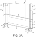
- FIG. 3 A is a fragmentary perspective view of a lower portion of the protective door package
- FIG. 3 B is a fragmentary front view of the lower portion of the protective door package
- FIG. 3 C is a fragmentary front view of the protective door package shown partially in phantom lines;
- FIG. 4 A is an exploded perspective view of the protective door package
- FIG. 4 B is an exploded front elevation view of the protective door package
- FIG. 5 is a perspective view of a single prehung door assembly
- FIG. 6 is a cross-sectional view of the single prehung door assembly taken along the line 6 - 6 of FIG. 5 ;
- FIG. 7 is a perspective view of a support spacer according to the first exemplary embodiment of the present invention.
- FIG. 8 is perspective view of unitized door packaging of the single unit protective door packages
- FIG. 9 is perspective view of the unitized door packaging engaged by a forklift
- FIG. 10 A is a front view of the single unit protective door package of the single prehung door assembly according to a second exemplary embodiment of the present invention.
- FIG. 10 B is a front view of the protective door package according to the second exemplary embodiment shown partially in phantom lines;
- FIG. 11 A is a fragmentary front view of a lower portion of the protective door package according to the second exemplary embodiment
- FIG. 11 B is a fragmentary front view of the lower portion of the protective door package according to the second exemplary embodiment shown partially in phantom lines;
- FIG. 12 A is a side view of the protective door package according to the second exemplary embodiment of the present invention.
- FIG. 12 B is a side view of the protective door package according to the second exemplary embodiment of the present invention shown partially in phantom lines;
- FIG. 13 A is an exploded perspective view of the protective door package according to the second exemplary embodiment
- FIG. 13 B is an exploded front elevation view of the protective door package according to the second exemplary embodiment
- FIG. 14 A is a front view of the single unit protective door package of the single prehung door assembly according to a third exemplary embodiment of the present invention.
- FIG. 14 B is a front view of the protective door package according to the third exemplary embodiment shown partially in phantom lines;
- FIG. 15 A is a fragmentary front view of a lower portion of the protective door package according to the third exemplary embodiment
- FIG. 15 B is a fragmentary front view of the lower portion of the protective door package according to the third exemplary embodiment shown partially in phantom lines;
- FIG. 16 A is a side view of the protective door package according to the third exemplary embodiment of the present invention.
- FIG. 16 B is a side view of the protective door package according to the third exemplary embodiment of the present invention shown partially in phantom lines;
- FIG. 17 A is an exploded perspective view of the protective door package according to the third exemplary embodiment.
- FIG. 17 B is an exploded front elevation view of the protective door package according to the third exemplary embodiment.
- FIG. 18 A is an exploded perspective view of a lower protective side cap according to the third exemplary embodiment with an extension panel in an unfolded configuration
- FIG. 18 B is an exploded front elevation view of the lower protective side cap according to the third exemplary embodiment with a support spacer.
- FIG. 18 C is an exploded front elevation view of the lower protective side cap according to the third exemplary embodiment with the extension panel in a folded configuration.
- FIGS. 1 A- 9 illustrate a single unit protective door package 10 for packaging of a single prehung door assembly 12 according to a first exemplary embodiment of the present invention.
- the prehung door assembly 12 is a conventional hinged residential door assembly, such as an interior or exterior door assembly, but it should be understood that the door assembly 12 may be a pivotally mounted exterior or interior door assembly provided for a residential or commercial building, such as a home, apartment, garage, condominium, hotel, office building, or the like.
- the prehung door assembly 12 may be a split jamb unit (i.e., door assembly), a flat jamb unit, an exterior frame unit, or a steel frame unit.
- the prehung door assembly 12 comprises a substantially rectangular door frame 14 , and a door slab 16 pivotally attached to the door frame 14 by at least one hinge (although typically two or more hinges are utilized), such as a “butt hinge” that includes two leaves.
- the door slab 16 has a bottom edge 17 .
- a door slab 16 is pre-cut for a doorknob and a strike plate.
- the prehung door assembly 12 may be made of any appropriate material, such as wood, metal, wood composite material, fiberglass reinforced polymer composite or the like.
- the door frame 14 includes a first (or right) vertically extending side jamb 15 1 , a second (or left) vertically extending side jamb 15 2 , which is parallel to and spaced from the first side jamb 15 1 , and a horizontally extending head jamb or header 20 that connects upper ends of the first and second side jambs 15 1 and 15 2 .
- Lower ends of the first and second side jambs 15 1 and 15 2 typically are interconnected by a threshold (not shown).
- a threshold not shown.
- the door frame 14 i.e., each of the first and second side jambs 15 1 and 15 2 of the door frame 14 ) has two opposite lowermost edges 15 L.
- the prehung door assembly 12 further comprises opposite front and back (or first and second) moldings (or trims) 18 F and 18 B, respectively, each connected to the door frame 14 along one of the side jambs 15 .
- the front moldings 18 F are connected to front edges 19 F of the door frame 14
- the back moldings 18 B are connected to back edges 19 B of the door frame 14 .
- Each of the front and back moldings 18 F and 18 B has an uppermost edge 23 1 and a lowermost edge 23 2 .
- the lowermost edges 23 2 of the front and back moldings 18 F, 18 B coincide (or match, correspond, are coplanar) with the lowermost edge 15 L of the door frame 14 .
- each of the front and back moldings 18 F and 18 B have opposite right and left (or first and second) outer side edges 24 and 26 , respectively.
- the front and back moldings 18 F, 18 B define a door frame channel 22 therebetween.
- the following discussion will sometimes use a reference numeral 18 without a subscript numeral to designate one or both of the front and back moldings 18 F and 18 B.
- the door frame 14 has opposite right and left upper corners 28 R and 28 L, respectively, defined by the front and back moldings 18 F and 18 B.
- the right upper corner 28 R of the door frame 14 is defined by the first side jamb 15 1 and the header jamb or header 20 , as well as by the uppermost edges 23 1 and the right outer side edges 26 of each of the front and back moldings 18 F and 18 B.
- the left and right lower corners of the door frame 14 are defined by the lowermost edge 15 L of the first and second side jambs 15 1 and 15 2 of the door frame 14 , as well as by the lowermost edges 23 2 of each of the front and back moldings 18 F and 18 B.
- a conventional door stop member 25 is fixed on an interior surface of at least one of the side jambs 15 of the door frame 14 , as best shown in FIGS. 3 A, 4 A and 5 , for limiting the movement of the door slab 16 by contacting the door slab 16 in a closed position.
- the single unit protective door package 10 of the first exemplary embodiment comprises the single prehung door assembly 12 , a pair of lower protective side caps 30 configured to be mounted at the lowermost edges 23 2 of the front and back moldings 18 F, 18 B and the lowermost edge 15 L of the door frame 14 , and a pair of structurally and geometrically identical upper protective side caps 34 configured to be mounted adjacent the uppermost edge 23 1 of the front and back moldings 18 F, 18 B.
- each of the upper protective side caps 34 is mounted to the door assembly at one of opposite upper corners 28 R and 28 L of the door frame 14 .
- each of the lower protective side caps 30 includes a base panel 31 and two side panels 32 forming therebetween a rectangular U-shaped open channel 33 .
- the lower protective side caps 30 are preferably formed from a corrugated cardboard blank or like material. It will be appreciated that other materials may be used for manufacturing the lower protective side caps 30 , such as corrugated plastic, extruded plastic, and the like.
- Each of the upper protective side caps 34 includes a base panel 35 , two side panels 36 and an end panel 37 together forming therebetween a rectangular U-shaped open cavity 38 . Unlike the open channel 33 of the lower protective side cap 30 , the cavity 38 is closed at one end by the end panel 37 , as best shown in FIG. 4 A .
- the upper protective side caps 34 are preferably formed from a corrugated cardboard blank. It will be appreciated that other materials may be used for manufacturing the upper protective side caps 34 .
- the lower protective side caps 30 are mounted to the door frame 14 of the door assembly 12 at the lowermost edge 23 2 of the front and back moldings 18 F and 18 B, so that the front and back moldings 18 F and 18 B are disposed in the open channel 33 of the lower protective side caps 30 .
- the base panel 32 engages the outer side edges 24 and 26 of the front and back moldings 18 F and 18 B.
- the upper protective side caps 34 are mounted to the door frame 14 of the door assembly 12 at the uppermost edge 23 1 of the front and back moldings 18 F and 18 B, so that the front and back moldings 18 F and 18 B are disposed in the open cavity 38 of the upper protective side caps 34 .
- the base panel 35 engages the outer side edges 24 and 26 of the front and back moldings 18 F and 18 B, while the end panel 37 engages the uppermost edges 23 1 of the front and back moldings 18 F, 18 B.
- the protective side caps 32 , 34 respectively, thus surround and protect the moldings 18 F and 18 B.
- the single unit protective door package 10 further comprises a pair of support spacers 40 (best shown in FIG. 7 ) mounted to the door frame 14 .
- Support spacers 40 are preferably structurally and geometrically identical. Support spacers 40 extend away from the lowermost edge 23 2 of the front and back moldings 18 F, 18 B and from the lowermost edge 15 L of the door frame 14 , as best shown in FIGS. 1 A- 3 C, and 7 .
- Each of the support spacers 40 includes an I-shaped base member 42 , a planar connecting member 44 and at least one, preferably two according to the first exemplary embodiment, planar support members 46 spaced from the connecting member 44 a distance equal to or slightly larger than the thickness of the door slab 16 .
- the two support members 46 are spaced from one another a distance equal to or slightly larger than the width of the door stop 25 the door slab 16 , i.e., sufficient to receive the door stop member 25 therebetween.
- the door stop member 25 is configured to dispose between the two support members 46 , as best shown in FIG. 3 A .
- Each of the support spacers 40 is formed as an integral part, such as through injection molding of a polymer material. Alternatively, other materials and manufacturing processes may be used.
- the base member 42 has a planar (i.e., flat) bottom surface 50 adapted to engage a floor surface, and a planar top surface 52 parallel to the planar bottom surface 50 , as best shown in FIG. 7 . Both the connecting member 44 and the support members 46 extend outwardly from the top surface 52 perpendicularly thereto.
- the connecting member 44 of each of the support spacers 40 according to the first exemplary embodiment has one or more (such as four, as illustrated in FIG.
- connecting holes 45 formed therethrough for securing (such as non-moveably securing or fastening) the support spacers 40 to the side jambs 15 by fasteners (such as screws or nails) extending through the connecting holes 45 .
- the support spacers 40 may be secured to the door frame 14 of the prehung door assembly 12 with or without fasteners.
- the support spacers 40 are configured to elevate the prehung door assembly 12 above the floor (off the ground) to a distance k (best shown in FIG. 1 A ) for compatibility with a 3.5′′ forklift, pallet jack or hand truck. Of course, other distances k may be utilized.
- the single unit protective door package 10 further comprises a door base protector 58 mounted to the bottom edge 17 of the door slab 16 , and at least two (bottom and top) packaging (or tightening) straps 60 each securing one of the lower and upper protective side caps 30 , 34 to the prehung door assembly 12 , as best shown in FIGS. 1 A- 2 B .
- the bottom and top tightening straps 60 encircle the prehung door assembly 12 , preferably about the lower and upper protective side caps 30 , 34 , respectively, thus forming the single unit protective door package 10 .
- the tightening straps 60 are made of polyester, nylon or other flexible materials.
- the protective straps 60 engage the protective side caps 30 , 34 , and thus minimize any damage to the moldings 18 F, B.
- a method of packaging the prehung door assembly 12 into the single unit protective door package 10 of the first exemplary embodiment follows.
- a support spacer 40 is mounted to each of the first and second side jambs 15 1 and 15 2 of the door frame 14 so as to extend away from the lowermost edge 23 2 of the front and back moldings 18 F, 18 B and from the lowermost edge 15 L of the door frame 14 , as best shown in FIGS. 1 A- 3 C .
- the connecting members 44 are positioned between the front and back moldings 18 F, 18 B so that the support members 46 and the connecting members 44 of the support spacers 40 engage the side jambs 15 therebetween, as best shown in FIGS. 3 A, 4 A and 4 B .
- each of the support spacers 40 engages the lowermost edge 15 L of the door frame 14 and the lowermost edge 23 2 of the front and back moldings 18 F and 18 B.
- the support spacers 40 may be secured to the side jambs 15 by fasteners (such as screws or nails) extending through the connecting holes 45 through the support members 46 .
- the lower protective side caps 30 are placed onto the prehung door assembly 12 . As best shown in FIG. 1 A- 3 C , the lower protective side caps 30 are positioned about the prehung door assembly 12 adjacent to the lowermost edges 15 L of the door frame 14 and the lowermost edges 23 2 of the front and back moldings 18 F and 18 B. When in position about the door assembly 12 , the base panel 32 of each of the lower protective side caps 30 engages the outer side edges 24 , 26 of the front and back moldings 18 F, 18 B and covers the door frame channel 22 between the moldings 18 .
- the side panels 32 of the lower protective side caps 30 engage outer surfaces of the front and back moldings 18 so that the front and back moldings 18 F, 18 B are positioned in the rectangular U-shaped open channels 33 of the lower protective side caps 30 between the two side panels 32 . Moreover, each of the lower protective side caps 30 engages the planar top surface 52 of one of the support spacers 40 .
- the lower protective side caps 30 are secured in position about the prehung door assembly 12 by one of the tightening straps 60 .
- the straps 6 are sufficiently tightened about the door assembly 12 to retain the side caps 30 in position.
- the door base protector 58 is mounted to the bottom edge 17 of the door slab 16 , such as through friction or by using a pressure sensitive adhesive or adhesive tape.
- the lower protective side caps 30 when secured in position about the door assembly 12 by the tightening strap 60 , cover and offer a degree of protection to the front and back moldings 18 F, 18 B in the corner regions of the door assembly 12 .
- the upper protective side caps 34 are placed onto the prehung door assembly 12 . As best shown in FIG. 1 A- 2 B , the upper protective side caps 34 are positioned about the prehung door assembly 12 adjacent to the uppermost edge 23 1 of the front and back moldings 18 F, 18 B of the door assembly 12 .
- the base panel 35 and the end panel 37 of each of the upper protective side caps 34 engage the outer side edges 24 , 26 of the front and back moldings 18 F, 18 B and cover the door frame channel 22 between the moldings 18 .
- the side panels 36 of the upper protective side caps 34 engage outer surfaces of the front and back moldings 18 F, 18 B so that the front and back moldings 18 F, 18 B are disposed in the rectangular U-shaped open cavity 38 between the two side panels 36 .
- the upper protective side caps 34 are secured in position about the prehung door assembly 12 by another tightening strap 60 .
- the strap 60 is sufficiently tightened to retain the protective side caps 34 in position to protect the moldings 18 F, B.
- the upper protective side caps 34 when secured in position about the door assembly 12 by the tightening straps 60 , cover and offer a degree of protection to the front and back moldings 18 F, 18 B in the corner regions of the door assembly 12 .
- a plurality, such as five, of the single unit protective door packages 10 may be unitized to form a unitized door packaging 70 , as illustrated in FIGS. 8 and 9 .
- the individual single unit protective door packages 10 are horizontally or vertically stacked, i.e., horizontally or vertically arranged next to and in contact with each other, as best shown in FIG. 8 . While we illustrate the door packages 10 in a vertically stacked orientation in FIGS. 8 - 9 , those skilled in the art will understand that a horizontal orientation may also be utilized. As illustrated in FIG.
- the single unit protective door packages 10 are aligned (i.e., colinear) with each other, so that the bottom surfaces 50 of the support spacers 40 of the single unit protective door packages 10 are aligned and coplanar.
- the stacked single unit protective door packages 10 are secured in a stacked orientation by at least top and bottom tightening straps 72 , as best shown in FIG. 8 .
- the tightening straps 72 are similar to straps 60 , although of a larger size and of sufficient strength to maintain the aligned door packages 10 in the assembled form during subsequent handling and transport.
- the aligned and coplanar support spacers 40 located on opposite sides of the door packages 10 , of the unitized door packaging 70 define a fork channel 74 therebetween configured to receive forwardly extending fork tines 78 of L-shaped forks 77 of a forklift vehicle 76 or of a pallet jack.
- the fork channel 74 thereby defines an opening such that the fork tines 78 of the forklift vehicle 76 or pallet jack can enter the fork channel 74 and support the unitized door packaging 70 .
- a forklift vehicle 76 or pallet jack may be used to lift the unitized door packaging 70 when the fork tines 78 thereof extend into the fork channel 74 of the unitized door packaging 70 , as best shown in FIG. 9 , and then transport the unitized door packaging 70 , such as for loading or unloading onto a truck or moved about a warehouse.
- FIGS. 10 A- 13 B Various modifications, changes, and alterations may be practiced with the above-described embodiment, including but not limited to the additional embodiment shown in FIGS. 10 A- 13 B .
- reference characters in FIGS. 10 A- 13 B that are discussed above in connection with FIGS. 1 - 9 are not further elaborated upon below, except to the extent necessary or useful to explain the additional embodiment of FIGS. 10 A- 13 B .
- Modified components and parts are indicated by the addition of a hundred digits to the reference numerals of the components or parts.
- FIGS. 10 A- 13 B A single unit protective door package 110 for a single prehung door assembly 12 according to a second exemplary embodiment is illustrated in FIGS. 10 A- 13 B .
- the single unit protective door package 110 of FIGS. 10 A- 13 B corresponds substantially to the single unit protective door package 10 of FIGS. 1 - 9 , and only portions of the single unit protective door package 110 which differ will therefore be explained in detail below.
- the single unit protective door package 110 comprises a pair of lower protective side caps 134 L mounted adjacent the lowermost edges 23 2 of the front and back moldings 18 F, 18 B and the lowermost edge 15 L of the door frame 14 , as best shown in FIGS. 10 A- 12 B .
- the protective door package 110 may further comprise a pair of upper protective side caps 134 T mounted adjacent the uppermost edge 23 1 of the front and back moldings 18 F, 18 B, as best shown in FIGS. 10 A, 10 B, 12 A and 12 B .
- the lower protective side caps 134 L and the upper protective side caps 134 T are preferably structurally and geometrically identical to each other in the second exemplary embodiment.
- the lower and upper protective side caps 134 L, 134 T are preferably structurally and geometrically identical to the upper protective side caps 34 of the first exemplary embodiment.
- the following discussion will sometimes use the reference numeral 134 without a character designating an entire group of substantially identical protective side caps.
- the reference numeral 134 will be used when generically referring to each of the lower and upper protective side caps 134 L and 134 T rather than reciting both reference numerals.
- Each of the protective side caps 134 includes a base panel 135 , two parallel side panels 136 , and an end panel 137 , together forming therebetween a rectangular U-shaped open cavity 138 . Cavity 138 is closed at one end by the end panel 137 , as best shown in FIG. 13 A .
- the protective side caps 134 are preferably formed from a corrugated cardboard material. It will be appreciated that other materials may be used for manufacturing the protective side caps 134 .
- the upper protective side caps 134 T are mounted onto the door frame 14 of the door assembly 12 at the uppermost edges 23 1 of the front and back moldings 18 F and 18 B. Accordingly, the front and back moldings 18 F and 18 B are disposed in the open cavity 138 of the upper protective side caps 134 T. Moreover, when mounted to the door frame 14 , the base panel 135 engages the outer side edges 24 and 26 of the front and back moldings 18 F and 18 B, while the end panel 137 engages the uppermost edges 23 1 of the front and back moldings 18 F, 18 B.
- the lower protective side caps 134 L are mounted to the door frame 14 of the door assembly 12 at the lowermost edges 23 2 of the front and back moldings 18 F and 18 B, so that the front and back moldings 18 F and 18 B are positioned in the open cavity 138 of the lower protective side caps 134 L. Moreover, when mounted to the door frame 14 , the base panel 135 of the lower protective side caps 134 L engages the outer side edges 24 and 26 of the front and back moldings 18 F and 18 B, while the end panel 137 is spaced from the lowermost edges 23 2 of the front and back moldings 18 F, 18 B and from the lowermost edges 15 L of the door frame 14 .
- the single unit protective door package 110 further comprises a pair of structurally and geometrically identical support spacers 140 .
- the spacers 140 are mounted to the door frame 14 and extend away from the lowermost edges 23 2 of the front and back moldings 18 F, 18 B and from the lowermost edges 15 L of the door frame 14 , as best shown in FIGS. 10 A, 10 B, 12 A and 12 B .
- Each of the support spacers 140 is preferably in the form of a hexahedron, such as cube or rectangular cuboid, as best shown in FIGS. 13 A and 13 B .
- Each of the support spacers 140 is disposed in the lower protective side caps 134 L so as to be in contact with the end panel 137 .
- the support spacers 140 are made of corrugated cardboard, plastic material, foam, rubber, etc., that has been rolled, folded or otherwise formed into rectangular cuboid configuration. In that configuration, the corrugations are oriented vertically, and their collective orientation is sufficient to support door package 110 .
- a method of packaging the prehung door assembly 12 into the single unit protective door package 110 of the second exemplary embodiment follows.
- one of the support spacers 140 is placed into each of the lower protective side caps 134 L, as best shown in FIG. 12 B , so as to contact the end panel 137 .
- the lower protective side caps 134 L are positioned onto the prehung door assembly 12 .
- the lower protective side caps 134 L are positioned about the prehung door assembly 12 adjacent to the lowermost edges 15 L of the door frame 14 and the lowermost edges 23 2 of the front and back moldings 18 F, 18 B.
- each of the support spacers 140 is disposed between the end panel 137 of one the lower protective side caps 134 L and the lowermost edge 15 L of the door frame 14 and the lowermost edge 23 2 of the front and back moldings 18 F, 18 B.
- the lower protective side caps 134 L are disposed outside the door frame 14 .
- each of the lower protective side caps 134 L engages the outer side edges 24 , 26 of the front and back moldings 18 F, 18 B and covers the door frame channel 22 between the moldings 18 F, 18 B.
- the side panels 136 of the lower protective side caps 134 L engage outer surfaces of the front and back moldings 18 F, 18 B.
- the lower protective side caps 134 L are secured in position about the prehung door assembly 12 by tightening at least a first strap 60 .
- the door base protector 58 is mounted to the bottom edge 17 of the door slab 16 , such as through a friction fit, adhesive, or adhesive tape.
- the lower protective side caps 134 L when secured in position about the door assembly 12 by the tightening straps 60 , cover and offer a degree of protection to the front and back moldings 18 in the lower corner regions of the door assembly 12 .
- the upper protective side caps 134 T are placed onto the prehung door assembly 12 .
- the upper protective side caps 134 T are positioned about the prehung door assembly 12 adjacent to the uppermost edge 23 1 of the front and back moldings 18 F, 18 B of the door assembly 12 .
- the base panel 135 and the end panel 137 of each of the upper protective side caps 134 T engages the outer side edges 24 , 26 of the front and back moldings 18 F, 18 B and covers the door frame channel 22 between the moldings 18 F, 18 B.
- the side panels 136 of the upper protective side caps 134 T engage outer surfaces of the front and back moldings 18 F, 18 B.
- the upper protective side caps 134 T are secured in position about the prehung door assembly 12 by at least a first tightening strap 60 .
- the upper protective side caps 134 T when secured in position about the door assembly 12 by the tightening strap 60 , cover and offer a degree of protection to the front and back moldings 18 F, 18 B in the upper corner regions of the door assembly 12 .
- a plurality, such as five, of the single unit protective door packages 110 of the second embodiment may be unitized to form a unitized door packaging (not shown) of the single unit protective door packages 110 .
- the individual single unit protective door packages 110 are horizontally or vertically stacked, i.e., horizontally or vertically arranged next to and in contact with each other.
- the door packages 110 may be stacked vertically or horizontally.
- the stacked single unit protective door packages 110 are secured in a stacked position by at least top and bottom tightening straps.
- the tightening straps resemble the straps 60 but are longer and have a greater tensile strength in order to hold the united packaging together during shipping and handling, such as onto and off a transport vehicle or truck.
- FIGS. 14 A- 18 C A single unit protective door package 210 for a single prehung door assembly 12 according to a third exemplary embodiment is illustrated in FIGS. 14 A- 18 C .
- the single unit protective door package 210 of FIGS. 14 A- 18 C corresponds substantially to the single unit protective door package 110 of FIGS. 10 A- 13 B , and only portions of the single unit protective door package 210 which differ will therefore be explained in detail below.
- the single unit protective door package 210 comprises a pair of lower protective side caps 230 mounted adjacent the lowermost edges 23 2 of the front and back moldings 18 F, 18 B and the lowermost edge 15 L of the door frame 14 , as best shown in FIGS. 14 A- 15 B .
- the protective door package 210 may further comprise a pair of upper protective side caps 34 mounted adjacent the uppermost edge 23 1 of the front and back moldings 18 F, 18 B, as best shown in FIGS. 14 A, 14 B and 16 A- 17 B .
- the protective side caps 34 and 230 are preferably formed from a corrugated cardboard material. It will be appreciated that other materials may be used for manufacturing the protective side caps 34 and 230 .
- Each of the lower protective side caps 230 includes a base panel 235 , two parallel side panels 236 , and an end panel 237 , together forming therebetween a rectangular U-shaped open cavity 238 .
- Cavity 238 is closed at one end by the end panel 237 , as best shown in FIGS. 17 A and 17 B .
- the base panel 235 is formed with a slot 254 therethrough, as best shown in FIGS. 18 A- 18 C .
- the single unit protective door package 210 further comprises a pair of structurally and geometrically identical support spacers 140 .
- the spacers 140 are mounted to the door frame 14 and extend away from the lowermost edges 23 2 of the front and back moldings 18 F, 18 B and from the lowermost edges 15 L of the door frame 14 , as best shown in FIGS. 14 B, 15 B, 17 A and 17 B .
- Each of the support spacers 140 is preferably in the form of a hexahedron, such as a cube or rectangular cuboid, as best shown in FIG. 17 A .
- Each of the support spacers 140 is disposed in the lower protective side caps 230 so as to be in contact with the end panel 237 .
- the support spacers 140 are made of corrugated cardboard, corrugated cardboard block, plastic material, foam, rubber, honeycomb block, etc., that has been rolled, folded or otherwise formed into rectangular cuboid configuration. In that configuration, the corrugations are oriented vertically, and their collective orientation is sufficient to support door package 210 .
- Each of the spacers 140 may include a cardboard sleeve encircling the rectangular cuboid in order to maintain it in that configuration.
- Each of the lower protective side caps 230 further includes an extension panel 239 including three extension sections: a proximal extension section 239 1 adjacent to the end panel 237 , a middle extension section 239 2 , and a distal extension section 239 3 .
- the extension sections 239 1 - 239 3 are connected to each other by fold lines 241 , as best shown in FIGS. 17 A- 18 C .
- the extension section 239 1 is connected to the end panel 237 by one of the fold lines 241 , as best shown in FIGS. 18 A- 18 C .
- the extension sections 239 1 - 239 3 of the extension panel 239 are foldable relative to each other and the end panel 237 so as to wrap over (or encapsulate) the spacer 140 , as best shown in FIGS. 18 B and 18 C .
- the fold lines 241 divide the extension panel 239 into the extension sections 239 1 - 239 3 arranged to be folded approximately 90° relative to each other and the end panel 237 to define an end box of generally rectangular cross section configured to house the spacer 140 therewithin, i.e., to transfer the extension panel 239 from an open (i.e., flat or unfolded) configuration to a folded configuration.
- FIGS. 17 A- 18 B show the extension panel 239 in the open configuration, while FIG.
- the extension panel 239 in the folded configuration.
- the middle extension section 239 2 of the extension panel 239 is provided with a tab 256 complementary to the slot 254 in the base panel 235 , as best shown in FIGS. 18 A- 18 C .
- the tab 256 may be formed by a cut line 257 , a series of perforations, or the like.
- the upper protective side caps 34 are mounted onto the door frame 14 of the door assembly 12 at the uppermost edges 23 1 of the front and back moldings 18 F and 18 B. Accordingly, the front and back moldings 18 F and 18 B are disposed in the open cavity 38 of the upper protective side caps 34 . Moreover, when mounted to the door frame 14 , the base panel 35 engages the outer side edges 24 and 26 of the front and back moldings 18 F and 18 B, while the end panel 37 engages the uppermost edges 23 1 of the front and back moldings 18 F, 18 B.
- the lower protective side caps 230 are mounted to the door frame 14 of the door assembly 12 at the lowermost edges 23 2 of the front and back moldings 18 F and 18 B, so that the front and back moldings 18 F and 18 B are positioned in the open cavity 238 of the lower protective side caps 230 . Moreover, when mounted to the door frame 14 , the base panel 235 of the lower protective side caps 230 engages the outer side edges 24 and 26 of the front and back moldings 18 F and 18 B, while the end panel 237 is spaced from the lowermost edges 23 2 of the front and back moldings 18 F, 18 B and from the lowermost edges 15 L of the door frame 14 , as illustrated in FIGS. 14 B, 15 B, 17 A and 17 B .
- a method of packaging the prehung door assembly 12 into the single unit protective door package 210 of the second exemplary embodiment follows.
- the width of the protective side caps 34 and 230 needed for the protective door package 210 is determined.
- 47 ⁇ 8′′ protective side caps are selected for 35 ⁇ 8′′ split jamb units (i.e., door assemblies) with casing, 57 ⁇ 8′′ protective side for 45 ⁇ 8′′ split jambs units with casing or for 47 ⁇ 8′′ flat jamb units.
- the proper size honeycomb support spacers 140 are inserted into the lower protective side caps 230 and placed on the end panel 237 within the channel 238 so as to ensure the spacer 140 fits side-to-side.
- the proximal extension section 239 1 of the lower protective side caps 230 is folded up, the middle extension section 239 2 is bent horizontally, and the distal extension section 239 3 of the extension panel 239 is bent upward.
- the tab 256 is separated from the distal extension section 239 3 along the cut line 257 and inserted into the slot 254 in the base panel 235 of the lower protective side caps 230 to secure the middle extension section 239 2 of the extension panel 239 to the base panel 235 of the lower protective side caps 230 .
- the lower protective side caps 230 are mounted to the left and right lower corners of the door frame 14 so that the support spacers 140 are under the lowermost edge 15 L of the door frame 14 and are separated therefrom by the middle extension section 239 2 of the lower protective side caps 230 .
- the packaging strap 60 is applied to the door assembly 12 as close as possible to the lowermost edge 15 L of the door frame 14 to secure the lower protective side caps 230 in position on the door assembly 12 .
- another packaging strap 60 may be applied above the first packaging strap 60 . The user has to ensure that both packaging straps 60 are secured.
- the upper protective side caps 34 are mounted to the door assembly 12 at the opposite upper corners 28 R and 28 L of the door frame 14 , and one or two packaging straps 60 are applied to secure the upper protective side caps 34 on the door assembly 12 .
- the single unit protective door package 210 is placed on a cart and verified that the lower protective side caps 230 with the support spacers 140 are secured.
- the single unit protective door packages 210 are prepared (e.g., 7 or 8), they are moved to a wrapper turnstile and grouped together in a pack of the protective door packages 210 . Once all protective door packages 210 are on the turnstile, the protective door packages 210 are oriented vertical and square, aligned evenly, left to right, so that the hinges are in line with the jamb of the adjacent protective door package 210 , and a clamp is placed near the top and tightened. Next, another clamp is placed on the opposite side of the first clamp slightly below the center of the pack and tightened.
- a banding strap is provided, slightly longer than one side of the pack of the protective door packages 210 , and stapled to each door, keeping the strap tight to help keep the doors from falling when a customer removes the shrink wrap and top banding strap.
- another banding strap is cut slightly longer than the circumference of the pack of the protective door packages 210 .
- This strap is placed around the top of the pack of the protective door packages 210 in-line with the header jamb. This location allows the strap to be tightened more and provides more stability to the pack when the clamps are removed.
- the top strap is tightened.
- the clamp is removed. Once the tightening process is completed, the excess strapping may be cut. Then the other clamp is removed.
- the pack of the protective door packages 210 is shrink wrapped to form the unitized door packaging of a plurality of the single unit protective door packages 230 .
- the protective door package of the present invention improves door packaging quality, protects prehung door assemblies from damage during shipping and handling, and eliminates the need for a wood pallet holding the protective door package.
Landscapes
- Engineering & Computer Science (AREA)
- Mechanical Engineering (AREA)
- Civil Engineering (AREA)
- Structural Engineering (AREA)
- Packaging Of Machine Parts And Wound Products (AREA)
- Pallets (AREA)
Abstract
Description
Claims (24)
Priority Applications (2)
| Application Number | Priority Date | Filing Date | Title |
|---|---|---|---|
| US18/077,408 US12065299B2 (en) | 2021-12-10 | 2022-12-08 | Protective door packaging for prehung door assemblies and method of packaging prehung door assemblies |
| US18/807,306 US20250051078A1 (en) | 2021-12-10 | 2024-08-16 | Protective door packaging for prehung door assemblies and method of packaging prehung door assemblies |
Applications Claiming Priority (2)
| Application Number | Priority Date | Filing Date | Title |
|---|---|---|---|
| US202163288183P | 2021-12-10 | 2021-12-10 | |
| US18/077,408 US12065299B2 (en) | 2021-12-10 | 2022-12-08 | Protective door packaging for prehung door assemblies and method of packaging prehung door assemblies |
Related Child Applications (1)
| Application Number | Title | Priority Date | Filing Date |
|---|---|---|---|
| US18/807,306 Continuation US20250051078A1 (en) | 2021-12-10 | 2024-08-16 | Protective door packaging for prehung door assemblies and method of packaging prehung door assemblies |
Publications (2)
| Publication Number | Publication Date |
|---|---|
| US20230182986A1 US20230182986A1 (en) | 2023-06-15 |
| US12065299B2 true US12065299B2 (en) | 2024-08-20 |
Family
ID=84974673
Family Applications (2)
| Application Number | Title | Priority Date | Filing Date |
|---|---|---|---|
| US18/077,408 Active 2042-12-08 US12065299B2 (en) | 2021-12-10 | 2022-12-08 | Protective door packaging for prehung door assemblies and method of packaging prehung door assemblies |
| US18/807,306 Pending US20250051078A1 (en) | 2021-12-10 | 2024-08-16 | Protective door packaging for prehung door assemblies and method of packaging prehung door assemblies |
Family Applications After (1)
| Application Number | Title | Priority Date | Filing Date |
|---|---|---|---|
| US18/807,306 Pending US20250051078A1 (en) | 2021-12-10 | 2024-08-16 | Protective door packaging for prehung door assemblies and method of packaging prehung door assemblies |
Country Status (4)
| Country | Link |
|---|---|
| US (2) | US12065299B2 (en) |
| CA (1) | CA3185048A1 (en) |
| GB (1) | GB2613957A (en) |
| MX (2) | MX2022015749A (en) |
Cited By (1)
| Publication number | Priority date | Publication date | Assignee | Title |
|---|---|---|---|---|
| US12578054B2 (en) * | 2024-03-22 | 2026-03-17 | Brian Desilets | Double door retainer |
Citations (22)
| Publication number | Priority date | Publication date | Assignee | Title |
|---|---|---|---|---|
| US2489029A (en) | 1949-05-04 | 1949-11-22 | Edmonds L Guerrant | Means for packing prefabricated doorframes |
| US2742146A (en) | 1953-06-30 | 1956-04-17 | Jr Lawson L Lester | Package unit for sectional frame and door construction |
| US2757854A (en) | 1953-02-09 | 1956-08-07 | Howard M Wall | Tube for packaging doors and the like |
| US2887241A (en) | 1955-08-11 | 1959-05-19 | Jack R Mackenzie | Nailless cleated container |
| US2929495A (en) | 1958-01-27 | 1960-03-22 | Robert F Simonsen | Packaging for assembled door and frame |
| US3017022A (en) | 1960-09-09 | 1962-01-16 | Amundson Moran Lee | Door assembly packaging |
| US3111724A (en) | 1961-05-29 | 1963-11-26 | Stanley J Piekarski | Door and frame assembly |
| US3301820A (en) | 1966-04-26 | 1967-01-31 | Roger M Haendiges | Pre-assembled door and casing therefor |
| US4127188A (en) | 1978-02-10 | 1978-11-28 | Anthony's Manufacturing Company, Inc. | Frangible door container |
| US4884687A (en) | 1987-05-07 | 1989-12-05 | Steves & Sons, Inc. | Door unit installation kit with packaging and display container |
| US4967905A (en) | 1987-05-07 | 1990-11-06 | Steves & Sons, Inc. | Door unit installation kit with packaging and display container |
| US5605229A (en) | 1995-02-27 | 1997-02-25 | Illinois Tool Works Inc. | Bulk vertical window package |
| US5740631A (en) * | 1994-11-17 | 1998-04-21 | Abe Kogyo Co., Ltd. | Door apparatus and a method for installing the same in a door opening of a building |
| US5809698A (en) * | 1996-09-06 | 1998-09-22 | Abe Kogyo Co., Ltd. | Door apparatus and method for installing the same in a door opening of a building |
| US6029410A (en) | 1998-01-20 | 2000-02-29 | Tenneco Packaging Inc. | Door guard |
| US6135030A (en) | 1994-12-16 | 2000-10-24 | The Servants, Inc. | Corrugated pallet and corrugated support members |
| US6216899B1 (en) | 1997-12-30 | 2001-04-17 | Edda Dorothy Bragazza Vicari | Dismountable container |
| US6581769B2 (en) | 2000-12-04 | 2003-06-24 | Robert Nist | Corrugated shipping container with self-hinged door |
| US20170081105A1 (en) | 2015-09-23 | 2017-03-23 | Express Products, Inc. | Shipping container for use with prehung door and frame assembly |
| US10029818B2 (en) | 2012-06-28 | 2018-07-24 | Daniel Kelly | Method of packaging a free standing machine using a multi-component base structure |
| US10399717B2 (en) | 2015-08-13 | 2019-09-03 | Thermoseal Industries, Llc | Door assembly packaging |
| US20240026692A1 (en) * | 2019-07-23 | 2024-01-25 | Llevitate Pty Ltd | Door frame support arrangement and method therefor |
-
2022
- 2022-12-08 US US18/077,408 patent/US12065299B2/en active Active
- 2022-12-08 MX MX2022015749A patent/MX2022015749A/en unknown
- 2022-12-08 MX MX2025011699A patent/MX2025011699A/en unknown
- 2022-12-09 GB GB2218590.4A patent/GB2613957A/en active Pending
- 2022-12-09 CA CA3185048A patent/CA3185048A1/en active Pending
-
2024
- 2024-08-16 US US18/807,306 patent/US20250051078A1/en active Pending
Patent Citations (22)
| Publication number | Priority date | Publication date | Assignee | Title |
|---|---|---|---|---|
| US2489029A (en) | 1949-05-04 | 1949-11-22 | Edmonds L Guerrant | Means for packing prefabricated doorframes |
| US2757854A (en) | 1953-02-09 | 1956-08-07 | Howard M Wall | Tube for packaging doors and the like |
| US2742146A (en) | 1953-06-30 | 1956-04-17 | Jr Lawson L Lester | Package unit for sectional frame and door construction |
| US2887241A (en) | 1955-08-11 | 1959-05-19 | Jack R Mackenzie | Nailless cleated container |
| US2929495A (en) | 1958-01-27 | 1960-03-22 | Robert F Simonsen | Packaging for assembled door and frame |
| US3017022A (en) | 1960-09-09 | 1962-01-16 | Amundson Moran Lee | Door assembly packaging |
| US3111724A (en) | 1961-05-29 | 1963-11-26 | Stanley J Piekarski | Door and frame assembly |
| US3301820A (en) | 1966-04-26 | 1967-01-31 | Roger M Haendiges | Pre-assembled door and casing therefor |
| US4127188A (en) | 1978-02-10 | 1978-11-28 | Anthony's Manufacturing Company, Inc. | Frangible door container |
| US4967905A (en) | 1987-05-07 | 1990-11-06 | Steves & Sons, Inc. | Door unit installation kit with packaging and display container |
| US4884687A (en) | 1987-05-07 | 1989-12-05 | Steves & Sons, Inc. | Door unit installation kit with packaging and display container |
| US5740631A (en) * | 1994-11-17 | 1998-04-21 | Abe Kogyo Co., Ltd. | Door apparatus and a method for installing the same in a door opening of a building |
| US6135030A (en) | 1994-12-16 | 2000-10-24 | The Servants, Inc. | Corrugated pallet and corrugated support members |
| US5605229A (en) | 1995-02-27 | 1997-02-25 | Illinois Tool Works Inc. | Bulk vertical window package |
| US5809698A (en) * | 1996-09-06 | 1998-09-22 | Abe Kogyo Co., Ltd. | Door apparatus and method for installing the same in a door opening of a building |
| US6216899B1 (en) | 1997-12-30 | 2001-04-17 | Edda Dorothy Bragazza Vicari | Dismountable container |
| US6029410A (en) | 1998-01-20 | 2000-02-29 | Tenneco Packaging Inc. | Door guard |
| US6581769B2 (en) | 2000-12-04 | 2003-06-24 | Robert Nist | Corrugated shipping container with self-hinged door |
| US10029818B2 (en) | 2012-06-28 | 2018-07-24 | Daniel Kelly | Method of packaging a free standing machine using a multi-component base structure |
| US10399717B2 (en) | 2015-08-13 | 2019-09-03 | Thermoseal Industries, Llc | Door assembly packaging |
| US20170081105A1 (en) | 2015-09-23 | 2017-03-23 | Express Products, Inc. | Shipping container for use with prehung door and frame assembly |
| US20240026692A1 (en) * | 2019-07-23 | 2024-01-25 | Llevitate Pty Ltd | Door frame support arrangement and method therefor |
Cited By (1)
| Publication number | Priority date | Publication date | Assignee | Title |
|---|---|---|---|---|
| US12578054B2 (en) * | 2024-03-22 | 2026-03-17 | Brian Desilets | Double door retainer |
Also Published As
| Publication number | Publication date |
|---|---|
| US20230182986A1 (en) | 2023-06-15 |
| MX2022015749A (en) | 2023-06-12 |
| GB202218590D0 (en) | 2023-01-25 |
| CA3185048A1 (en) | 2023-06-10 |
| GB2613957A (en) | 2023-06-21 |
| US20250051078A1 (en) | 2025-02-13 |
| MX2025011699A (en) | 2025-11-03 |
Similar Documents
| Publication | Publication Date | Title |
|---|---|---|
| EP1612159B1 (en) | Package, method and kit for stretch hood packaging of home appliances | |
| EP0974530B1 (en) | Packaging member | |
| US7748527B2 (en) | Panel packaging system | |
| US5605229A (en) | Bulk vertical window package | |
| US8061521B1 (en) | Packaging system for a large article | |
| US20060151410A1 (en) | Product tray insert | |
| US20250051078A1 (en) | Protective door packaging for prehung door assemblies and method of packaging prehung door assemblies | |
| US10399717B2 (en) | Door assembly packaging | |
| US8141708B2 (en) | Container for glass products | |
| KR20230112980A (en) | Packaging box with reinforced internal structure to protect the contents | |
| CA2656176A1 (en) | Container for glass products | |
| CN219407703U (en) | A fiber laser packaging box | |
| CA2610935C (en) | A secondary package | |
| US5042665A (en) | Packaging frame | |
| US8341923B2 (en) | Packaging window coverings | |
| KR100400872B1 (en) | Packaging box for wire bobbin | |
| JP2000355323A (en) | Assembly, folding storage box | |
| KR102874682B1 (en) | Folding box pallet | |
| CA2268296A1 (en) | Article protector and method of use and manufacture | |
| US11987419B2 (en) | Collapsible pallet casing assembly and use thereof | |
| JP2591909B2 (en) | Insulated foldable container | |
| JP3524794B2 (en) | Refrigerated showcase packaging | |
| CN115667078B (en) | Box-shaped housing, kit for manufacturing such box-shaped housing and use thereof | |
| GB2148255A (en) | Palletized packing cases | |
| KR20030030641A (en) | Packing box structure using vinyl |
Legal Events
| Date | Code | Title | Description |
|---|---|---|---|
| FEPP | Fee payment procedure |
Free format text: ENTITY STATUS SET TO UNDISCOUNTED (ORIGINAL EVENT CODE: BIG.); ENTITY STATUS OF PATENT OWNER: LARGE ENTITY |
|
| STPP | Information on status: patent application and granting procedure in general |
Free format text: DOCKETED NEW CASE - READY FOR EXAMINATION |
|
| AS | Assignment |
Owner name: MASONITE CORPORATION, FLORIDA Free format text: ASSIGNMENT OF ASSIGNORS INTEREST;ASSIGNORS:FARISH, STEVEN;ABBAS, TOM;BURBA, GARRETT;AND OTHERS;SIGNING DATES FROM 20220106 TO 20220110;REEL/FRAME:063920/0295 |
|
| STPP | Information on status: patent application and granting procedure in general |
Free format text: NON FINAL ACTION MAILED |
|
| STPP | Information on status: patent application and granting procedure in general |
Free format text: RESPONSE TO NON-FINAL OFFICE ACTION ENTERED AND FORWARDED TO EXAMINER |
|
| STPP | Information on status: patent application and granting procedure in general |
Free format text: NOTICE OF ALLOWANCE MAILED -- APPLICATION RECEIVED IN OFFICE OF PUBLICATIONS |
|
| STPP | Information on status: patent application and granting procedure in general |
Free format text: PUBLICATIONS -- ISSUE FEE PAYMENT VERIFIED |
|
| STCB | Information on status: application discontinuation |
Free format text: ABANDONMENT FOR FAILURE TO CORRECT DRAWINGS/OATH/NONPUB REQUEST |
|
| STPP | Information on status: patent application and granting procedure in general |
Free format text: PUBLICATIONS -- ISSUE FEE PAYMENT VERIFIED |
|
| STCF | Information on status: patent grant |
Free format text: PATENTED CASE |
|
| AS | Assignment |
Owner name: WELLS FARGO BANK, NATIONAL ASSOCIATION, AS COLLATERAL AGENT, TEXAS Free format text: SECURITY INTEREST;ASSIGNOR:METRIE INC.;REEL/FRAME:073874/0281 Effective date: 20260224 |
|
| AS | Assignment |
Owner name: METRIE INC., WASHINGTON Free format text: ASSIGNMENT OF ASSIGNORS INTEREST;ASSIGNOR:MASONITE CORPORATION;REEL/FRAME:074552/0001 Effective date: 20260224 |