US12062996B2 - Synchronizing grid side harmonic filter and pre-charging cell capacitors in modular multilevel converters - Google Patents
Synchronizing grid side harmonic filter and pre-charging cell capacitors in modular multilevel converters Download PDFInfo
- Publication number
- US12062996B2 US12062996B2 US17/762,315 US202017762315A US12062996B2 US 12062996 B2 US12062996 B2 US 12062996B2 US 202017762315 A US202017762315 A US 202017762315A US 12062996 B2 US12062996 B2 US 12062996B2
- Authority
- US
- United States
- Prior art keywords
- cell
- circuit breaker
- capacitors
- charging
- grid
- Prior art date
- Legal status (The legal status is an assumption and is not a legal conclusion. Google has not performed a legal analysis and makes no representation as to the accuracy of the status listed.)
- Active, expires
Links
Images


Classifications
-
- H—ELECTRICITY
- H02—GENERATION; CONVERSION OR DISTRIBUTION OF ELECTRIC POWER
- H02M—APPARATUS FOR CONVERSION BETWEEN AC AND AC, BETWEEN AC AND DC, OR BETWEEN DC AND DC, AND FOR USE WITH MAINS OR SIMILAR POWER SUPPLY SYSTEMS; CONVERSION OF DC OR AC INPUT POWER INTO SURGE OUTPUT POWER; CONTROL OR REGULATION THEREOF
- H02M7/00—Conversion of AC power input into DC power output; Conversion of DC power input into AC power output
- H02M7/42—Conversion of DC power input into AC power output without possibility of reversal
- H02M7/44—Conversion of DC power input into AC power output without possibility of reversal by static converters
- H02M7/48—Conversion of DC power input into AC power output without possibility of reversal by static converters using discharge tubes with control electrode or semiconductor devices with control electrode
- H02M7/483—Converters with outputs that each can have more than two voltages levels
- H02M7/487—Neutral point clamped inverters
-
- H—ELECTRICITY
- H02—GENERATION; CONVERSION OR DISTRIBUTION OF ELECTRIC POWER
- H02J—ELECTRIC POWER NETWORKS; CIRCUIT ARRANGEMENTS OR SYSTEMS FOR SUPPLYING OR DISTRIBUTING ELECTRIC POWER; SYSTEMS FOR STORING ELECTRIC ENERGY
- H02J3/00—Circuit arrangements for AC mains or AC distribution networks
- H02J3/38—Arrangements for feeding a single network from two or more generators or sources in parallel; Arrangements for feeding already energised networks from additional generators or sources in parallel
- H02J3/381—Dispersed generators
-
- H—ELECTRICITY
- H02—GENERATION; CONVERSION OR DISTRIBUTION OF ELECTRIC POWER
- H02M—APPARATUS FOR CONVERSION BETWEEN AC AND AC, BETWEEN AC AND DC, OR BETWEEN DC AND DC, AND FOR USE WITH MAINS OR SIMILAR POWER SUPPLY SYSTEMS; CONVERSION OF DC OR AC INPUT POWER INTO SURGE OUTPUT POWER; CONTROL OR REGULATION THEREOF
- H02M1/00—Details of apparatus for conversion
- H02M1/12—Arrangements for reducing harmonics from AC input or output
- H02M1/126—Arrangements for reducing harmonics from AC input or output using passive filters
-
- H—ELECTRICITY
- H02—GENERATION; CONVERSION OR DISTRIBUTION OF ELECTRIC POWER
- H02M—APPARATUS FOR CONVERSION BETWEEN AC AND AC, BETWEEN AC AND DC, OR BETWEEN DC AND DC, AND FOR USE WITH MAINS OR SIMILAR POWER SUPPLY SYSTEMS; CONVERSION OF DC OR AC INPUT POWER INTO SURGE OUTPUT POWER; CONTROL OR REGULATION THEREOF
- H02M1/00—Details of apparatus for conversion
- H02M1/36—Means for starting or stopping converters
-
- H—ELECTRICITY
- H02—GENERATION; CONVERSION OR DISTRIBUTION OF ELECTRIC POWER
- H02M—APPARATUS FOR CONVERSION BETWEEN AC AND AC, BETWEEN AC AND DC, OR BETWEEN DC AND DC, AND FOR USE WITH MAINS OR SIMILAR POWER SUPPLY SYSTEMS; CONVERSION OF DC OR AC INPUT POWER INTO SURGE OUTPUT POWER; CONTROL OR REGULATION THEREOF
- H02M7/00—Conversion of AC power input into DC power output; Conversion of DC power input into AC power output
- H02M7/42—Conversion of DC power input into AC power output without possibility of reversal
- H02M7/44—Conversion of DC power input into AC power output without possibility of reversal by static converters
- H02M7/48—Conversion of DC power input into AC power output without possibility of reversal by static converters using discharge tubes with control electrode or semiconductor devices with control electrode
- H02M7/483—Converters with outputs that each can have more than two voltages levels
- H02M7/4835—Converters with outputs that each can have more than two voltages levels comprising two or more cells, each including a switchable capacitor, the capacitors having a nominal charge voltage which corresponds to a given fraction of the input voltage, and the capacitors being selectively connected in series to determine the instantaneous output voltage
-
- F—MECHANICAL ENGINEERING; LIGHTING; HEATING; WEAPONS; BLASTING
- F03—MACHINES OR ENGINES FOR LIQUIDS; WIND, SPRING, OR WEIGHT MOTORS; PRODUCING MECHANICAL POWER OR A REACTIVE PROPULSIVE THRUST, NOT OTHERWISE PROVIDED FOR
- F03D—WIND MOTORS
- F03D9/00—Adaptations of wind motors for special use; Combinations of wind motors with apparatus driven thereby; Wind motors specially adapted for installation in particular locations
- F03D9/20—Wind motors characterised by the driven apparatus
- F03D9/25—Wind motors characterised by the driven apparatus the apparatus being an electrical generator
- F03D9/255—Wind motors characterised by the driven apparatus the apparatus being an electrical generator connected to electrical distribution networks; Arrangements therefor
-
- H—ELECTRICITY
- H02—GENERATION; CONVERSION OR DISTRIBUTION OF ELECTRIC POWER
- H02J—ELECTRIC POWER NETWORKS; CIRCUIT ARRANGEMENTS OR SYSTEMS FOR SUPPLYING OR DISTRIBUTING ELECTRIC POWER; SYSTEMS FOR STORING ELECTRIC ENERGY
- H02J2101/00—Supply or distribution of decentralised, dispersed or local electric power generation
- H02J2101/20—Dispersed power generation using renewable energy sources
- H02J2101/28—Wind energy
-
- H02J2300/28—
-
- H—ELECTRICITY
- H02—GENERATION; CONVERSION OR DISTRIBUTION OF ELECTRIC POWER
- H02M—APPARATUS FOR CONVERSION BETWEEN AC AND AC, BETWEEN AC AND DC, OR BETWEEN DC AND DC, AND FOR USE WITH MAINS OR SIMILAR POWER SUPPLY SYSTEMS; CONVERSION OF DC OR AC INPUT POWER INTO SURGE OUTPUT POWER; CONTROL OR REGULATION THEREOF
- H02M1/00—Details of apparatus for conversion
- H02M1/0095—Hybrid converter topologies, e.g. NPC mixed with flying capacitor, thyristor converter mixed with MMC or charge pump mixed with buck
-
- Y—GENERAL TAGGING OF NEW TECHNOLOGICAL DEVELOPMENTS; GENERAL TAGGING OF CROSS-SECTIONAL TECHNOLOGIES SPANNING OVER SEVERAL SECTIONS OF THE IPC; TECHNICAL SUBJECTS COVERED BY FORMER USPC CROSS-REFERENCE ART COLLECTIONS [XRACs] AND DIGESTS
- Y02—TECHNOLOGIES OR APPLICATIONS FOR MITIGATION OR ADAPTATION AGAINST CLIMATE CHANGE
- Y02E—REDUCTION OF GREENHOUSE GAS [GHG] EMISSIONS, RELATED TO ENERGY GENERATION, TRANSMISSION OR DISTRIBUTION
- Y02E10/00—Energy generation through renewable energy sources
- Y02E10/70—Wind energy
- Y02E10/72—Wind turbines with rotation axis in wind direction
Definitions
- Embodiments presented in this disclosure generally relate to Modular Multilevel Converters (MMCs) and the capacitors included therein. Particular embodiments herein describe synchronizing and pre-charging schema for the filters and capacitors.
- MMCs Modular Multilevel Converters
- Wind Turbine Generators are an increasing popular source for generating electricity and may be deployed singly or in groups of several wind turbines, often referred to as a wind farm.
- MMCs can be used to electrically link two powered systems running different voltage/current schemas. When initiating a link between two powered systems, the MMC equalizes the differences in voltages/currents between the two systems to reduce power surges (e.g., inrush current from the higher voltage side to the lower voltage side) and other aberrant effects.
- an MMC can equalize the difference via a DC (Direct Current) link located between the machine side converter (MSC) and line side converter (LSC) that is charged to a predefined level before contact is made via a series of charging components (e.g., one or more transformers, diode bridges, current limiter resistors, fuses, circuit breakers, switches, etc.)
- DC Direct Current
- LSC line side converter
- One embodiment of the present disclosure is a method comprising; initializing contactors to connect a power grid to a harmonic filter and a modular multilevel converter, wherein the MMC is disposed between the power grid and a generator and the harmonic filter is disposed between the power grid and the MMC, wherein initializing the contactors comprises: opening a transmission circuit breaker disposed on a first path, wherein the transmission circuit breaker is disposed between the power grid and the MMC, and closing a pre-charging contactor disposed on a second path, wherein the pre-charging contactor is disposed between the power grid and the MMC, wherein the second path is parallel to the first path and includes a set of pre-charge resistors; connecting the power grid to the MMC and the harmonic filter over the second path; pre-charging cell capacitors in the MMC in an un-driven stage; in response to a cell voltage of the cell capacitors satisfying a driving threshold, pre-charging the cell capacitors in a driven stage; and in response to the cell voltage satisfying a charge
- the driving threshold is based on a peak phase-to-phase voltage of a grid voltage divided by a number of cell capacitors disposed on a given phase of the MMC.
- the driven stage employs a progressive driving schema to iteratively increase a number of cell capacitors bypassed at a given time by one relative to a preceding time to boost a charge level in non-bypassed cell capacitors.
- the driven stage employs a halving driving schema to exponentially increase a number of cell capacitors bypassed at a given time relative to a preceding time to boost a charge level in non-bypassed cell capacitors.
- the method further comprises: after connecting the generator, opening the pre-charging contactor.
- a resistance of the pre-charge resistors is selected based on an impedance of the harmonic filter at a grid frequency of the power grid.
- the driven stage places a given dual-cell in the MMC into operational modes including: a natural blocking mode, for charging a first cell capacitor and a second cell capacitor in the given dual-cell; a first forced bypass mode, for charging the first cell capacitor and bypassing the second cell capacitor; a second forced bypass mode, for charging the second cell capacitor and bypassing the first cell capacitor; and a third forced bypass mode, for bypassing the first cell capacitor and the second cell capacitor.
- a Power Conversion and Transmission System comprising: a grid circuit breaker, disposed to selectively connect a power grid with the Power Conversion and Transmission System; a Modular Multilevel Converter, including a plurality of cells each including cell switches and a cell capacitor; a generator circuit breaker, disposed to selectively connect a generator with a machine side converter of the MMC; a harmonic filter, connected to a transmission line connected to a line side converter of the MMC, wherein the transmission line defines a first path when a transmission circuit breaker is closed and a second path when a pre-charging contactor is closed, wherein the first path connects the grid circuit breaker with the harmonic filter and the line side converter, wherein the second path connects the grid circuit breaker with the harmonic filter and the line side converter over a pre-charge resistor, and wherein the first path is parallel to the second path and bypasses the pre-charge resistors; and a controller configured to pre-charge the cell capacitors and synchronize the harmonic filter with the power
- each cell of the plurality of cells is a dual cell that includes two cell capacitors and four cell switches.
- the controller is further configured to open the pre-charging contactor after closing the generator circuit breaker.
- the forced bypass modes bypass at least one cell capacitor included in the cells to apply a rectified voltage from the power grid across a subset of the cell capacitors.
- the controller is further configured to cease boosting the cell voltage in response to the cell voltage in the cell capacitors satisfying the charge and place the cells in an operational mode in anticipation of inverting and rectifying power supplied from the generator for provision to the power grid.
- a resistance of the pre-charge resistor is configured to be at less than 10% of an impedance of the harmonic filter at a grid frequency of the power grid.
- the system in combination with any system described above or below, is further configured for three-phase power transmission.
- controller unit a for a Power Conversion and Transmission System comprising: a processor; and a memory, including pre-charging control logic that when executed by the processor, enable the controller unit to perform an operation comprising: initializing circuit breakers to connect a power grid to a harmonic filter and to a converter system, wherein initializing the circuit breakers includes: opening a transmission circuit breaker disposed on a first path, wherein the transmission circuit breaker is disposed between the power grid and the converter system; and closing a pre-charging contactor disposed on a second path, wherein the pre-charging contactor is disposed between the power grid and the converter system, wherein the second path includes a set of pre-charge resistors, wherein the second path is parallel to the first path which bypasses the set of pre-charge resistors; connecting the power grid to the converter system and the harmonic filter over the second path; selectively charging cell capacitors in the converter system over a series of iterations until a charge threshold is reached, wherein each iteration
- FIG. 1 illustrates a diagrammatic view of a wind turbine, according to an embodiment described in this present disclosure.
- FIG. 2 illustrates a diagrammatic view of the components internal to the nacelle and tower of a wind turbine, according to an embodiment described in this present disclosure.
- FIG. 3 illustrates a schematic of a power conversion and transmission system, according to embodiments of the present disclosure.
- FIG. 4 is a schematic of a Modular Multilevel Converter for use as a converter system, according to embodiments of the present disclosure.
- FIG. 5 is a schematic of a harmonic filter, according to embodiments of the present disclosure.
- FIGS. 6 A- 6 E are a series of schematics of cells in various modes of operation, according to embodiments of the present disclosure.
- FIGS. 7 A and 7 B illustrate operations of the Line Side Converter and Machine Side Converter, according to embodiments of the present disclosure.
- FIG. 8 is a flowchart for synchronizing a harmonic filter while pre-charging cells in a Modular Multilevel Converter, according to embodiments of the present disclosure.
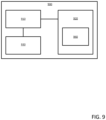
- FIG. 9 is a block diagram of a controller unit as may be used as a controller, according to one or more embodiments of the present disclosure.
- the MMC After the un-driven stage, the MMC enters a driven or controlled stage, during which the charge of the cell capacitors is boosted to the rated operation voltage by progressively reducing the number of cell capacitors to which the grid applies a voltage in series to at a time.
- the MMC swaps or interchanges which capacitors are subject to the charging currents in the driven stage until all of the capacitors have reached a threshold voltage, at which point normal operations of the MMC may begin.
- FIG. 1 illustrates a diagrammatic view of a horizontal-axis wind turbine generator (WTG) 100 .
- the WTG 100 typically comprises a tower 102 and a wind turbine nacelle 104 located at the top of the tower 102 .
- a wind turbine rotor 106 may be connected with the nacelle 104 through a low speed shaft extending out of the nacelle 104 .
- the wind turbine rotor 106 comprises three rotor blades 108 mounted on a common hub 110 which rotate in a rotor plane, but may comprise any suitable number of blades, such as one, two, four, five, or more blades.
- the blades 108 typically each have an aerodynamic shape with a leading edge 112 for facing into the wind, a trailing edge 114 at the opposite end of a chord for the blades 108 , a tip 116 , and a root 118 for attaching to the hub 110 in any suitable manner.
- the blades 108 may be connected to the hub 110 using pitch bearings 120 such that each blade 108 may be rotated around its longitudinal axis to adjust the blade's pitch.
- the pitch angle of a blade 108 relative to the rotor plane may be controlled by linear actuators, hydraulic actuators, or stepper motors, for example, connected between the hub 110 and the blades 108 .
- FIG. 2 illustrates a diagrammatic view of typical components internal to the nacelle 104 and tower 102 of a WTG 100 .
- the rotor 106 spins and rotates a low-speed shaft 202 .
- Gears in a gearbox 204 mechanically convert the low rotational speed of the low-speed shaft 202 into a relatively high rotational speed of a high-speed shaft 208 suitable for generating electricity using a generator 206 .
- a controller 210 may sense the rotational speed of one or both of the shafts 202 , 208 . If the controller decides that the shaft(s) are rotating too fast, the controller may signal a braking system 212 to slow the rotation of the shafts, which slows the rotation of the rotor 106 —i.e., reduces the revolutions per minute (RPM). The braking system 212 may prevent damage to the components of the WTG 100 .
- the controller 210 may also receive inputs from an anemometer 214 (providing wind speed) and/or a wind vane 216 (providing wind direction). Based on information received, the controller 210 may send a control signal to one or more of the blades 108 in an effort to adjust the pitch 218 of the blades.
- the rotational speed of the rotor (and therefore, the shafts 202 , 208 ) may be increased or decreased.
- the controller 210 may send a control signal to an assembly comprising a yaw motor 220 and a yaw drive 222 to rotate the nacelle 104 with respect to the tower 102 , such that the rotor 106 may be positioned to face more (or, in certain circumstances, less) upwind.
- FIG. 3 illustrates a schematic of a power conversion and transmission system (PCTS) 300 , according to embodiments of the present disclosure.
- PCTS power conversion and transmission system
- the PCTS 300 illustrated in FIG. 3 is a three-phase system that carries power of three different phases on three separate transmission lines 301 a - c (generally, transmission line 301 ), although PCTS 300 of one, two, or more phases with a corresponding number of transmission lines 301 a -N can also employ the teachings of the present disclosure.
- each component of the PCTS 300 either includes N instances, where each instance a-N is associated with one phase a-N, or is connected to each of the N phases.
- a converter system 310 receives alternating current (AC) power from a generator 320 (e.g., a WTG 100 ) on a number of generator lines 302 a - c (generally, generator line 302 ) corresponding to a number of phases of power generated by the generator 320 .
- a generator 320 e.g., a WTG 100
- generator line 302 generator line 302
- the converter system 310 rectifies the AC power to a direct current (DC) power, and inverts the DC power to another AC power that is suitable to be supplied to a power grid 330 via the transmission lines 301 .
- the frequency that the power grid 330 receives power can be different than the frequency at which the generator 320 provides power.
- a power grid transformer 340 can adjust the voltage of the AC power output by the converter system 310 to an appropriate voltage for the power grid 330 (e.g., a grid voltage), and a harmonic filter 350 connected to the transmission lines 301 between the converter system 310 and the grid transformer 340 (or grid 330 ) can be used to condition and adjust the AC power provided to the grid 330 .
- the components of a three-phase harmonic filter 350 are discussed in greater detail in regard to FIG. 5 .
- a controller 900 in communication with various components and current or voltage sensors 371 a , 371 b (generally, sensors 371 ) disposed throughout the PCTS 300 may control the operation of the generator 320 , auxiliary power source (APS) 370 , auxiliary transformer 380 , and/or various switches to affect whether and how power is provided to/from the grid 330 or components within the PCTS 300 .
- the controller 900 may be fed power from the APS 370 and is in communication with the various components of the PCTS 300 via wireless channels or wired connections (not illustrated). The components of a controller 900 are discussed in greater detail in regard to FIG. 9 .
- circuit breakers and/or contactors 360 a - f are disposed at various points in the PCTS 300 to direct or block the transmission of power to/from particular portions of the PCTS 300 .
- a grid circuit breaker 360 a disposed between the grid 330 and the grid transformer 340 can act as a Point of Common Coupling (PCC) between the PCTS 300 and the grid 330 to connect or disconnect the PCTS 300 to/from the grid 330 .
- PCC Point of Common Coupling
- an auxiliary transformer circuit breaker 360 b and an APS circuit breaker 360 c can connect or disconnect an auxiliary transformer 380 to/from the converter system 310 and the APS 370 respectively.
- the auxiliary transformer circuit breaker 360 b is a medium voltage circuit breaker disposed between the grid 330 and the auxiliary transformer 380 to isolate the auxiliary transformer 380 from faults or during service/inspection on the primary side.
- the APS circuit breaker 360 c is a low voltage circuit breaker disposed between the auxiliary transformer 380 and the APS 370 to protect against faults on the APS side (or secondary side) of the auxiliary transformer 380 or during de-energization of the auxiliary equipment powered via the APS 370 .
- a generator circuit breaker 360 d disposed between the generator 320 and the converter system 310 can connect or disconnect the generator 320 to/from the converter system 310 .
- a transmission circuit breaker 360 e is disposed on a first path between the converter system 310 (and the harmonic filter 350 ) and the grid transformer 340 .
- the transmission circuit breaker 360 e can include a first set of switches 361 e to make or break electrical contact on the electrical transmission lines 301 between the converter system 310 and the grid 330 , and a second set of switches 362 e to make or break electrical contact on an electrical pathway between ground and the transmission lines 301 .
- a pre-charging contactor 360 f is disposed on a second path in the PCTS 300 .
- the second path may alternatively be referred to as a pre-charge path, as the second path provides an alternative pathway around the transmission circuit breaker 360 e (i.e., connects to the transmission lines 301 both a first point upstream and a second point downstream of the first set of switches 361 e of the transmission circuit breaker 360 e ) and is used when pre-charging the converter system 310 .
- the pre-charging contactor 360 f can include a first set of switches 361 f to make or break electrical contact on the electrical transmission lines 301 between the converter system 310 and the power grid 330 , and a second set of switches 362 f to make or break electrical contact on an electrical pathway between ground and the transmission lines 301 .
- the pre-charging contactor 360 f also includes (or can be associated with) a set of fuses 363 f on the transmission lines 301 and a set of pre-charge resistors 390 , which ensure that a pre-charging current provided from the power grid 330 does not exceed the designed capabilities of the converter system 310 .
- the pre-charge resistors 390 are provided with a predefined resistance, which is selected based on the impedance of the harmonic filter 350 .
- the controller 900 blocks or allows (respectively) current from the grid 330 to flow over the first path through the transmission circuit breaker 360 e to the converter system 310 .
- the controller 900 blocks or allows (respectively) current from the grid 330 to flow over the second path through the pre-charging contactor 360 f to the converter system 310 . Due to the presence of the pre-charge resistors 390 on the second path and lack of similar resistors on the first path, current prefers to flow over the first path when both paths are available.
- the controller 900 blocks the first path (i.e., opens the transmission circuit breaker 360 e ) and allows the second path (i.e., closes the pre-charging contactor 360 f ) when pre-charging the converter system 310 .
- the first set of switches 361 f in the pre-charging contactor 360 f and the switches in the grid circuit breaker 360 a are closed.
- the first set of switches 361 e , in the transmission circuit breaker 360 e , the second set of switches 362 e in the transmission circuit breaker 360 e , the second set of switches 362 f in the pre-charging contactor 360 f , the switches in the generator circuit breaker 360 d are open, and the switches in the auxiliary transformer circuit breaker 360 b are closed.
- power from the grid 330 flows on the transmission lines 301 into the PCTS 300 and over the pre-charge resistors 390 to the harmonic filter 350 and the converter system 310 .
- FIG. 4 is a schematic of an MMC 400 for use as a converter system 310 according to embodiments of the present disclosure.
- the MMC 400 operates by converting the AC power supplied by the generator 320 to DC power via a Machine Side Converter (MSC) 410 , and from DC power back to AC power for supply to the grid 330 via a Line Side Converter (LSC) 420 .
- the MSC 410 and the LSC 420 are coupled together via a DC link 430 .
- Various switches in the MSC 410 and LSC 420 control how the MMC 400 is charged or discharged and how power is rectified or inverted, which may be controlled by the controller 900 or another subordinate or independent control device.
- Each of the MSC 410 and the LSC 420 include several cells, which can be modularly added or removed from the converters in series with one or more other cells to adjust the capabilities of the converters in handling different voltage inputs and outputs when converting power from AC to DC or from DC to AC.
- the cells include various switches and capacitors, which are discussed in greater detail in regard to FIGS. 6 A- 6 E .
- the DC link 430 carries DC power between the MSC 410 and the LSC 420 on a first rail 401 a and a second rail 401 b (generally, rail 401 ), and includes DC-link capacitors 440 a - b (generally, DC-link capacitor 440 ) disposed between the rails 401 .
- the DC-link capacitors 440 regulate a DC voltage between the MSC 410 and the LSC 420 .
- the DC-link capacitors 440 are connected to a neutral (common) voltage node connected to earth ground through a transmission resistor 450 and the non-common terminals of the DC-link capacitors 440 are connected to opposing DC-link voltage rails 401 (e.g., to one of a positive or a negative rail 401 ).
- the DC-link may include more or fewer DC-link capacitors 440 (including none) in other embodiments.
- An operator pre-charges the DC-link capacitors 440 and the capacitors in the MSC 410 and LSC 420 before connecting the generator 320 to the grid 330 (via the converter system 310 and associated circuit breakers 360 ) to reduce the amount of inrush current.
- the controller 900 manages the switches in the MMC 400 to gradually build power across the rails 401 to charge the capacitors to store a threshold voltage before connecting the converter system 310 to the generator 320 .
- the generator 320 is soft started via the MSC 410 and are at a standstill until the MMC 400 has completed pre-charge.
- the pre-charging of the capacitors is performed in parallel (i.e., at substantially the same time) with the synchronization of the harmonic filter 350 to the grid power.
- FIG. 5 is a schematic of a harmonic filter 350 according to embodiments of the present disclosure.
- FIG. 5 may be understood in conjunction with FIG. 3 .
- the harmonic filter 350 is shunt connected with the transmission lines 301 between the converter system 310 and the grid 330 .
- the harmonic filter 350 mitigates the risks and effects of different current frequencies between the grid 330 and the converter system 310 causing harmonic currents in the PCTS 300 using a set of resonant circuits connected to each transmission line 301 .
- the harmonic filter 350 may be a double-tuned filter, high-pass filter, etc., in other embodiments.
- the harmonic filter 350 includes, connected on a first side to each corresponding transmission line 301 , filter fuses 510 a - c (generally, filter fuse 510 ), inductors 520 a - c (generally, filter inductors 520 ), and filter capacitors 530 a - c (generally, filter capacitors 530 ) that are connected on a second side to a shared node 540 .
- the filter fuses 510 protect the filter inductors 520 and filter capacitors 530 on the same line from over currents from the transmission line 301 associated with a difference between the grid voltage and the stored voltage in the harmonic filter 350 .
- the filter inductors 520 are selected to have a filter inductance of L f
- the filter capacitors 530 are selected to have a filter capacitance of C f that result in a filter impedance at grid frequency (generally, 50 Hz or 60 Hz ⁇ 10%) that is significantly higher than the resistance R pre of the pre-charge resistors 390 (i.e.,
- the resistance R pre is less than 10% of the filter impedance Z filter (i.e., 0.1*
- the voltage drop over the pre-charge resistors 390 is also negligible, and the voltage V f of the harmonic filter 350 and the grid voltage V g are substantially equal in magnitude (e.g.,
- ). Accordingly, for an angular speed of ⁇ , based on the grid frequency f (e.g., ⁇ 2 ⁇ f), the values for the pre-charge resistors 390 , filter inductors 520 , and filter capacitors 530 are selected according to Formula 1.
- FIG. 6 A- 6 E are a series of schematics of dual-cells 600 in various modes of operation, according to embodiments of the present disclosure.
- Each of the dual-cells 600 in FIGS. 6 A- 6 E allow for rectification or inversion of current by the controlled switching and discharge of the components therein.
- a series of nodes 610 a - e (generally, node 610 or cell node) are provided in each of the dual-cells 600 .
- a first node 610 a and a fifth node 610 e are contacts for the dual-cell 600 by which the dual-cell 600 can be connected to another dual-cell 600 , a rail 402 , arm reactor 710 (discussed in relation to FIGS. 7 A and 7 B ), or other component external to the dual-cell 600 .
- the illustrated dual-cells 600 include a first cell capacitor 620 a (generally, cell capacitor 620 ) disposed between a second node 610 b and a third node 610 c , and a second cell capacitor 620 b disposed between the third node 610 c and a fourth node 610 d .
- a first cell capacitor 620 a generally, cell capacitor 620
- second cell capacitor 620 b disposed between the third node 610 c and a fourth node 610 d .
- four-switch two-capacitor cells, other cells with more or fewer switches and capacitors may be used in other embodiments.
- two two-switch, one-capacitor cells may be treated as one four-switch, two-capacitor cell if arranged to exhibit similar component-to-node arrangements.
- the switches 630 a - d (generally, switch 630 or cell switch) are arranged in parallel with corresponding diodes 640 a - d (generally, diode 640 ), and are driven open or closed to define various operating modes in the dual-cell 600 .
- a first switch 630 a and first diode 640 a are disposed between the first node 610 a and the second node 610 b , wherein the first diode 640 a is biased to block current flowing from the second node 610 b to the first node 610 a .
- a second switch 630 b and second diode 640 b are disposed between the first node 610 a and the third node 610 c , wherein the second diode 640 b is biased to block current flowing from the first node 610 a to the third node 610 c .
- a third switch 630 c and third diode 640 c are disposed between the third node 610 c and the fifth node 610 e , wherein the third diode 640 c is biased to block current flowing from the third node 610 c to the fifth node 610 e .
- a fourth switch 630 d and fourth diode 640 d are disposed between the fifth node 610 e and the fourth node 610 d , wherein the fourth diode 640 d is biased to block current flowing from the fifth node 610 e to the fourth node 610 d.
- the switches 630 When driven to a closed state by the controller 900 , the switches 630 provide a pathway that bypasses the associated diode 640 , thus allowing current to flow counter to the bias of the associated diode 640 and thereby bypass one or more cell capacitors 620 in the dual-cell 600 .
- the switches 630 may include other power semiconductor devices (e.g., a power Metal Oxide Semiconductor Field Effect Transistor (MOSFET) or Bipolar Junction Transistor (BJT)).
- the controller 900 (not illustrated) can thereby control whether a given switch 630 is open or closed by controlling the gate of the associated power semiconductor device.
- the paired switches 630 and diodes 640 may be included in a single package or integrated component, or may be provided as discrete circuit components.
- a single-cell in contrast to a dual-cell 600 , includes one cell capacitor 620 and two switches 630 (with associated diodes 640 ); effectively half of a dual-cell 600 .
- the modes of operation of a single-cell include a natural bypass mode (in which the switches 630 are not conducting), a natural blocked mode (in which current flows over the cell capacitor 620 ), and a forced blocked mode (in which the switches 630 are conducting to avoid charging the cell capacitor 620 ).
- FIG. 6 A illustrates a natural bypass mode of operation of a dual-cell 600 , where a first current flow 601 runs from the fifth node 610 e , through the third diode 640 c to the third node 610 c , and through the second diode 640 b to the first node 610 a .
- the switches 630 are not conducting.
- the natural bypass mode is achieved without driving the switches 630 (i.e., all of the switches 630 may remain open); current naturally flows from the fifth node 610 e to the first node 610 a when a higher voltage is applied to the fifth node 610 e than the first node 610 a.
- FIG. 6 B illustrates a natural blocked mode of operation of a dual-cell 600 , where a second current flow 602 runs from the first node 610 a , through the first diode 640 a , first cell capacitor 620 a , and second cell capacitor 620 b to the fourth node 610 d , and through the fourth diode 640 d to the fifth node 610 e .
- the switches 630 are open, and the second current flow 602 flowing over the cell capacitors 620 charges the cell capacitors 620 .
- the natural blocked mode is achieved without driving the switches 630 (i.e., all of the switches 630 may remain open); current naturally flows from the first node 610 a to the fifth node 610 e over the cell capacitors 620 when a higher voltage is applied to the first node 610 a than the fifth node 610 e.
- FIG. 6 C illustrates a first forced bypass mode of operation of a dual-cell 600 , where a third current flow 603 runs from the first node 610 a , through the first diode 640 a and first cell capacitor 620 a to the third node 610 c , and through the closed third switch 630 c to the fifth node 610 e .
- the first, second, and fourth switches 630 a , 630 b , 630 d are open, and the third switch 630 c is closed, thus charging the first cell capacitor 620 a , and not charging the second cell capacitor 620 b.
- FIG. 6 D illustrates a second forced bypass mode of operation of a dual-cell 600 , where a fourth current flow 604 runs from the first node 610 a , through the closed second switch 630 b to the third node 610 c , and second cell capacitor 620 b to the fourth node 610 d , and through the fourth diode 640 d to the fifth node 610 e .
- the first, third, and fourth switches 630 a , 630 c , 630 d are open, and the second switch 630 b is closed, thus charging the second cell capacitor 620 b , and not charging the first cell capacitor 620 a.
- FIG. 6 E illustrates a third forced bypass mode of operation of a dual-cell 600 , where a fifth current flow 605 runs from the first node 610 a , through the closed second switch 630 b to the third node 610 c , and through the closed third switch 630 c to the fifth node 610 e .
- the first and fourth switches 630 a , 630 d are open, and the second and third switches 630 b , 630 c are closed, thus bypassing and not charging the cell capacitors 620 .
- the selective closing of one or more switches 630 alters the pathway that current flows from the first node 610 a to the fifth node 610 e , thus altering how the cell capacitors 620 charge compared to the natural blocked mode of FIG. 6 B .
- the voltage may be divided across the two cell capacitors 620 (as per the natural block mode), directed solely across one cell capacitor 620 (as per the first and second forced bypass modes), or none of the cell capacitors 620 (as per the third forced bypass mode).
- V cell in the N cell capacitors 620 of a given phase arm may be given as per Formula 2, where V peak is the peak phase-to-phase voltage of the grid 330 or power source used in pre-charging.
- V cell V peak ⁇ N (2)
- one or more cell capacitors 620 are bypassed; dividing the voltage over fewer cell capacitors 620 and allowing for a higher charge in the non-bypassed cell capacitors 620 , which may be expressed according to Formula 3, where K is the number of cell capacitors 620 bypassed (i.e., over which current does not flow).
- V cell V peak ⁇ ( N ⁇ K ) (3)
- the controller 900 selects which dual-cells 600 to operate in a given mode of operation to selectively charge the sum of voltages on the cell capacitors 620 up to the peak voltage V peak (less any voltage drops across the diodes 640 and resistive losses) or another pre-charging threshold set by an operator.
- Various sensors 371 e.g., voltage probes 371 a - b across the cell capacitors 620 a - b ) allow the controller 900 to measure how the cell capacitors 620 are charging, and for the controller 900 to balance how quickly individual or a subset of the cell capacitors 620 are charging by controlling the switches 630 to charge or not charge the associated cell capacitors 620 at a given time when pre-charging the MMC 400 .
- FIGS. 7 A and 7 B illustrate the LSC 420 and MSC 410 respectively in association with the charging paths for a phase AB positive current (i.e., V ab >0), according to embodiments of the present disclosure.
- Charging currents for the other phases (i.e., BC, AC), and negative currents thereof, have been omitted from FIGS. 7 A and 7 B for clarity, but are contemplated by the present disclosure.
- the LSC layout 700 a in FIG. 7 A may be understood to be linked with the MSC layout 700 b in FIG. 7 B by node A on the first rail 401 a (as a positive rail 401 in the present example), and node B on the second rail 401 b (as a negative rail 401 in the present example).
- the LSC layout 700 a for a three-phase MMC 400 includes three legs connected between the transmission lines 301 and the rails 401 , each connected to a respective one of the three transmission lines 301 a - c .
- Each leg includes a plurality of dual-cells 600 , of which half are disposed between the corresponding transmission lines 301 a - c and the first rail 401 a , and may be referred to as a positive arm 730 a - c (generally, positive arm 730 or positive LSC arm) based on the corresponding transmission line 301 a - c .
- the other half of the dual-cells 600 are disposed between the corresponding transmission line 301 and the second voltage rail 401 b , and may be referred to as a negative arm 740 a - c (generally, negative arm 740 or negative LSC arm) based on the corresponding transmission line 301 a - c .
- Each half of the legs is also associated with a leg inductance, represented by a arm inductor 710 .
- the MSC layout 700 b for a three-phase MMC 400 includes three legs connected between the generator lines 302 and the rails 401 , each connected to a respective one of the three generator lines 302 a - c .
- Each leg includes a plurality of dual-cells 600 , of which half are disposed between the corresponding generator lines 302 a - c and the first voltage rail 401 a , and may be referred to as a positive arm 750 a - c (generally, positive arm 750 or positive MSC arm) based on the corresponding generator line 302 a - c .
- the other half of the dual-cells 600 is disposed between the corresponding generator line 302 a - c and the second voltage rail 401 b , and may be referred to as a negative arm 760 a - c (generally, negative arm 760 or negative MSC arm) based on the corresponding generator line 302 a - c .
- Each half of the legs is also associated with a leg inductance, represented by arm inductor 710 .
- FIGS. 7 A and 7 B Three current loops 770 a - c (generally, current loop 770 ) are shown in FIGS. 7 A and 7 B flowing inward from the first transmission line 301 a and outward to the second transmission line 301 b.
- the first current loop 770 a carries current from the first transmission line 301 a through the first positive arm 730 a onto the first rail 401 a , and from the first rail 401 a through the second positive arm 730 b to the second transmission line 301 b.
- the second current loop 770 b carries current from the first transmission line 301 a through the first positive arm 730 a onto the first rail 401 a , from the first rail 401 a through the positive and negative MSC arms to the second rail 401 b , and from the second rail 401 b through the second negative arms 740 b to the second transmission line 301 b.
- the third current loop 770 c carries current from the first transmission line 301 a through the first negative arm 740 a onto the second rail 401 b , and from the second rail 401 b through the second negative arm 740 b to the second transmission line 301 b.
- the dual-cells 600 in the first positive arm 730 a and the second negative arm 740 b are operated in the natural bypass mode (as per FIG. 6 A ), such that the first, second, and third current loops 770 a - c do not charge the cell capacitors 620 in those dual-cells 600 (e.g., passing through the respective second and third diodes 640 b - c ).
- a controller 900 may drive the cell switches to force the dual-cells 600 into a forced bypass mode (per FIGS. 6 C- 6 E ), or may leave the cell switches un-driven to leave the dual-cells 600 to conduct current in a natural mode of operation (per FIGS. 6 A- 6 B ).
- the controller 900 can then selectively drive one or more cells (e.g., turn on one or two bypass switches in a dual-cell 600 ) to boost the charge level in the cell capacitors 620 .
- the controller 900 drives the switches 630 in one or more dual-cells 600 such that selected dual-cells 600 operate any one of the natural modes of operations and the forced bypass modes of operation.
- the dual-cells 600 in the second positive arm 730 b , the first negative arm 740 a , and the MSC arms are operated in any one of the natural blocked mode, first forced bypass mode, second forced bypass mode, and third forced bypass mode (as per FIGS.
- the controller 900 may force a bypass mode in a given dual-cell 600 to boost the charging of the cell capacitors 620 in an arm in total close to V peak , to account for manufacturing tolerances between cell capacitors 620 (e.g., to equalize the stored charge), etc.
- FIG. 8 is a flowchart of a method 800 for synchronizing a harmonic filter 350 while pre-charging the dual cells 600 in an MMC 400 , according to embodiments of the present disclosure.
- Method 800 begins with block 810 , where the controller 900 initializes the open/closed state of various circuit breakers 360 .
- a generator circuit breaker 360 d remains open to disconnect the generator 320 from the converter system 310 being pre-charged.
- a first set of switches 361 f in a pre-charging contactor 360 f are closed and a first set of switches 361 e in a transmission circuit breaker 360 e are opened to direct power from the grid transformer 340 over a set of pre-charge resistors 390 before reaching the harmonic filter 350 and the converter system 310 .
- method 800 proceeds to block 820 , where the controller 900 ensures that the grid circuit breaker 360 a is closed to thereby connect the grid 330 to the harmonic filter 350 and the converter system 310 over the pre-charge resistors 390 and to provide power from the grid 330 (over the auxiliary transformer 380 ) to the APS 370 and controller 900 .
- the MMC 400 enters into an un-driven stage of pre-charging, where the controller 900 monitors the status of the dual-cells 600 and the voltages of the cell capacitors 620 , but does not drive the switches 630 in the dual-cells 600 .
- the voltage in the harmonic filter 350 equalizes (less any voltage drops over the pre-charge resistors 390 ) with the grid voltage V g
- the voltage V cell-LSC across the cell capacitors 620 in the LSC 420 equalizes to the peak phase-to-phase voltage of the grid 330 V peak , divided by the number of cell capacitors 620 N in each arm of the LSC
- the controller 900 leaves the switches 630 in all of the dual-cells 600 open; allowing current to flow through the dual-cells 600 according to the natural bypass mode or natural blocking mode (per FIGS. 6 A and 6 B , respectively).
- Method 800 may remain at block 830 until a measured voltage satisfies a driving threshold.
- the measured voltage may be a voltage V f stored in the filter capacitors 530 compared against a driving threshold based on the grid voltage V g (e.g., x % of V g ).
- the measured voltage may be a voltage V cell-LSC in the one of the cell capacitors 620 (or an average, highest, or lowest V cell-LSC measured across several cell capacitors 620 ) compared against a driving threshold based on the peak phase-to-phase voltage V peak (e.g., x % of V peak ⁇ N).
- the measured voltage may be a voltage V cell-MSC in the one of the cell capacitors 620 (or an average, highest, or lowest V cell-MSC measured across several cell capacitors 620 ) compared against a driving threshold based on the peak phase-to-phase voltage V peak (e.g., x % of V peak ⁇ N). Once the measured voltage satisfies the driving threshold, method 800 proceeds to block 840 .
- the MMC 400 enters into a driven stage of pre-charging, where the controller 900 continues to monitor the status of the dual-cells 600 and the voltage of the cell capacitors 620 , but may actively drive the switches 630 in the dual-cells 600 to boost the charge stored in the cell capacitors 620 .
- the status of the dual-cells 600 can include the health of the various electronics included in the dual-cell 600 , including the cell switches 630 , communication and temperature sensors, pressure sensors, etc.
- the controller 900 drives the switches 630 in the MSC 410 and the LSC 420 to decrease the number of cell capacitors 620 over which the voltage from the grid 330 is applied using the different forced bypass modes to gradually increase the voltage applied across the cell capacitors 620 ; applying the rectified or peak grid phase-to-phase voltage V Peak across a subset of the cell capacitors 620 over the diodes 640 .
- the controller 900 can thus cycle through which cell capacitors 620 are bypassed in an arm, and which are charged until a charge threshold is reached.
- the controller 900 may thus cycle through bypassing greater percentages of the cell capacitors 620 to double the voltage applied across the cell capacitors 620 in each arm until a charge threshold is reached.
- the controller 900 may thus be configured for pre-charging the cell capacitors 620 to account for inherent differences in the circuitry of the dual-cells 600 in a series of iterations where each successive iteration includes a smaller subset of cell capacitors 620 charged at a given time to a correspondingly higher cell voltage V cell .
- Method 800 may remain at block 840 until a measured voltage satisfies a charge threshold.
- pre-charging is complete, and the controller 900 closes the first set of switches 361 e in the transmission circuit breaker, closes the generator circuit breaker 360 d , and begins switching the converter system 310 to rectify and invert the power produced by the generator 320 for supply to the power grid 330 rather than to boost the charge levels in the cell capacitors 620 .
- the first set of switches 361 f in the pre-charging contactor 360 f remain closed until after the first set of switches 361 e in the transmission circuit breaker 360 e are closed.
- the difference in resistance on the two paths over the transmission lines i.e., through the transmission circuit breaker 360 e and through the pre-charging contactor 360 f ) cause the current to bypass the pre-charge resistors 390 while maintaining the synchronization to the grid 330 in the harmonic filter 350 established during the pre-charging of the dual-cells 600 from the grid 330 .
- Method 800 may then conclude as the PCTS 300 enters normal operations, where the generator 320 provides power to the grid 330 via the converter system 310 , which rectifies and inverts the power for consumption by the grid 330 .
- the controller 900 may continue to control the switches 630 in the cells to affect rectification and inversion, and continue to control the circuit breakers 360 ; optionally opening the pre-charging contactor 360 f after normal operations have begun.
- FIG. 9 is a block diagram of a controller unit 900 , according to one or more embodiments.
- the controller unit 900 includes one or more computer processors 910 and a memory 920 (e.g., a memory storage device).
- the one or more processors 910 represent any number of processing elements that each can include any number of processing cores.
- the memory 920 can include volatile memory elements (such as random access memory), non-volatile memory elements (such as solid-state, magnetic, optical, or Flash-based storage), and combinations thereof.
- the memory 920 can be distributed across different mediums (e.g., network storage or external hard drives).
- the one or more processors 910 are communicatively coupled with a communication system 930 to send/receive communication via fiber optic cables, electrical wires, and/or radio signals with various sensors 371 , circuit breakers/contactors 360 , switches 630 and other controller units 900 associated with the WTG 100 , APS 370 , and auxiliary transformer 380 , etc.
- the memory 920 may include a plurality of “modules” for performing various functions described herein.
- each module includes program code that is executable by one or more of the processors 910 .
- other embodiments may include modules that are partially or fully implemented in hardware (i.e., circuitry) or firmware.
- the memory 920 includes a pre-charging control logic 940 that enables the controller unit 900 to charge the cell capacitors 620 while synchronizing the harmonic filter 350 to the grid 330 as described herein.
- the pre-charging control logic 940 is preloaded with setpoints and thresholds for various control schemes, such as are described in relation to FIG. 8 by way of example.
- aspects disclosed herein may be embodied as a system, method or computer program product. Accordingly, aspects may take the form of an entirely hardware embodiment, an entirely software embodiment (including firmware, resident software, micro-code, etc.) or an embodiment combining software and hardware aspects that may all generally be referred to herein as a “circuit,” “module” or “system.” Furthermore, aspects may take the form of a computer program product embodied in one or more computer readable medium(s) having computer readable program code embodied thereon.
- the present invention may be a system, a method, and/or a computer program product.
- the computer program product may include a computer-readable storage medium (or media) (e.g., a portable computer diskette, a hard disk, a random access memory (RAM), a read-only memory (ROM), an erasable programmable read-only memory (EPROM or Flash memory), an optical fiber, a portable compact disc read-only memory (CD-ROM), an optical storage device, a magnetic storage device, or any suitable combination of the foregoing) having computer readable program instructions thereon for causing a processor to carry out aspects of the present invention.
- a computer-readable storage medium e.g., a portable computer diskette, a hard disk, a random access memory (RAM), a read-only memory (ROM), an erasable programmable read-only memory (EPROM or Flash memory), an optical fiber, a portable compact disc read-only memory (CD-ROM), an optical storage device, a magnetic storage device, or any suitable combination of
- each block in the flowchart or block diagrams may represent a module, segment or portion of code, which comprises one or more executable instructions for implementing the specified logical function(s).
- the functions noted in the block may occur out of the order noted in the figures. For example, two blocks shown in succession may, in fact, be executed substantially concurrently, or the blocks may sometimes be executed in the reverse order, depending upon the functionality involved.
Landscapes
- Engineering & Computer Science (AREA)
- Power Engineering (AREA)
- Inverter Devices (AREA)
- Charge And Discharge Circuits For Batteries Or The Like (AREA)
Abstract
Description
V cell =V peak ÷N (2)
V cell =V peak÷(N−K) (3)
V cell-LSC=2*V cell-MSC (4)
Claims (14)
Applications Claiming Priority (4)
| Application Number | Priority Date | Filing Date | Title |
|---|---|---|---|
| DKPA201970575 | 2019-09-19 | ||
| DK201970575 | 2019-09-19 | ||
| DKPA201970575 | 2019-09-19 | ||
| PCT/DK2020/050257 WO2021052547A1 (en) | 2019-09-19 | 2020-09-17 | Synchronizing grid side harmonic filter and pre-charging cell capacitors in modular multilevel converters |
Publications (2)
| Publication Number | Publication Date |
|---|---|
| US20220337147A1 US20220337147A1 (en) | 2022-10-20 |
| US12062996B2 true US12062996B2 (en) | 2024-08-13 |
Family
ID=72643952
Family Applications (1)
| Application Number | Title | Priority Date | Filing Date |
|---|---|---|---|
| US17/762,315 Active 2041-06-14 US12062996B2 (en) | 2019-09-19 | 2020-09-17 | Synchronizing grid side harmonic filter and pre-charging cell capacitors in modular multilevel converters |
Country Status (4)
| Country | Link |
|---|---|
| US (1) | US12062996B2 (en) |
| EP (1) | EP4032178A1 (en) |
| CN (1) | CN114731117B (en) |
| WO (1) | WO2021052547A1 (en) |
Families Citing this family (5)
| Publication number | Priority date | Publication date | Assignee | Title |
|---|---|---|---|---|
| WO2021052546A1 (en) * | 2019-09-19 | 2021-03-25 | Vestas Wind Systems A/S | Modular multilevel converter pre-charging |
| CN114731117B (en) * | 2019-09-19 | 2026-03-10 | 维斯塔斯风力系统集团公司 | Synchronous grid side harmonic filter and pre-charge battery capacitor in modular multilevel converter |
| EP4402786B1 (en) * | 2021-09-13 | 2026-03-25 | Hitachi Energy Ltd | Charging of a modular multilevel converter |
| US12015276B2 (en) | 2022-02-16 | 2024-06-18 | Ge Infrastructure Technology Llc | System and method for pre-charging a DC link of a power converter |
| EP4525240A1 (en) * | 2023-09-14 | 2025-03-19 | Siemens Gamesa Renewable Energy A/S | Method and circuit for protecting a grid filter of a wind turbine |
Citations (13)
| Publication number | Priority date | Publication date | Assignee | Title |
|---|---|---|---|---|
| US20110013441A1 (en) | 2009-07-15 | 2011-01-20 | Rainer Gruber | Static converter and method for starting up the converter |
| US20130313826A1 (en) | 2010-10-28 | 2013-11-28 | Vestas Wind Systems A/S | Wind turbine generator |
| US20160211762A1 (en) * | 2015-01-15 | 2016-07-21 | Rockwell Automation Technologies, Inc. | Modular multilevel converter and charging circuit therefor |
| US20170271997A1 (en) * | 2014-12-12 | 2017-09-21 | Abb Schweiz Ag | Standby and charging of modular multilevel converters |
| US20170294847A1 (en) | 2016-04-08 | 2017-10-12 | Delta Electronics (Shanghai) Co., Ltd. | Pre-charge control method |
| US20180115164A1 (en) | 2015-03-16 | 2018-04-26 | General Electric Technology Gmbh | Start-up of hvdc networks |
| WO2018091051A1 (en) | 2016-11-17 | 2018-05-24 | Vestas Wind Systems A/S | Modular multi-level converter with full-bridge cell fault current blocking for wind-turbines |
| US20190288509A1 (en) * | 2015-12-18 | 2019-09-19 | Abb Schweiz Ag | Voltage balancing in a modular multilevel converter having delta configuration |
| US10673353B2 (en) * | 2017-05-30 | 2020-06-02 | Abb Schweiz Ag | Converter cell with integrated photovoltaic cell |
| US10886858B1 (en) * | 2019-10-15 | 2021-01-05 | University Of Tennessee Research Foundation | Modular multi-level converter pre-chargers |
| WO2021052547A1 (en) | 2019-09-19 | 2021-03-25 | Vestas Wind Systems A/S | Synchronizing grid side harmonic filter and pre-charging cell capacitors in modular multilevel converters |
| US20220278604A1 (en) * | 2019-09-19 | 2022-09-01 | Vestas Wind Systems A/S | Modular multilevel converter pre-charging |
| US20220311241A1 (en) * | 2021-03-26 | 2022-09-29 | Tianjin University | Source-network Coordination Type Direct-current (DC) Circuit Breaker Based on pre-charged Capacitors for Modular Multilevel Converters (MMC) Based DC Grid |
Family Cites Families (2)
| Publication number | Priority date | Publication date | Assignee | Title |
|---|---|---|---|---|
| CN104901360B (en) * | 2015-05-15 | 2017-03-08 | 中国科学院电工研究所 | A control method for a supercapacitor cascaded high voltage device |
| CN105610336B (en) * | 2016-01-27 | 2018-07-27 | 东南大学 | MMC type multiport electric power electric transformer based on double capacitance modules |
-
2020
- 2020-09-17 CN CN202080080548.5A patent/CN114731117B/en active Active
- 2020-09-17 EP EP20780090.5A patent/EP4032178A1/en active Pending
- 2020-09-17 WO PCT/DK2020/050257 patent/WO2021052547A1/en not_active Ceased
- 2020-09-17 US US17/762,315 patent/US12062996B2/en active Active
Patent Citations (13)
| Publication number | Priority date | Publication date | Assignee | Title |
|---|---|---|---|---|
| US20110013441A1 (en) | 2009-07-15 | 2011-01-20 | Rainer Gruber | Static converter and method for starting up the converter |
| US20130313826A1 (en) | 2010-10-28 | 2013-11-28 | Vestas Wind Systems A/S | Wind turbine generator |
| US20170271997A1 (en) * | 2014-12-12 | 2017-09-21 | Abb Schweiz Ag | Standby and charging of modular multilevel converters |
| US20160211762A1 (en) * | 2015-01-15 | 2016-07-21 | Rockwell Automation Technologies, Inc. | Modular multilevel converter and charging circuit therefor |
| US20180115164A1 (en) | 2015-03-16 | 2018-04-26 | General Electric Technology Gmbh | Start-up of hvdc networks |
| US20190288509A1 (en) * | 2015-12-18 | 2019-09-19 | Abb Schweiz Ag | Voltage balancing in a modular multilevel converter having delta configuration |
| US20170294847A1 (en) | 2016-04-08 | 2017-10-12 | Delta Electronics (Shanghai) Co., Ltd. | Pre-charge control method |
| WO2018091051A1 (en) | 2016-11-17 | 2018-05-24 | Vestas Wind Systems A/S | Modular multi-level converter with full-bridge cell fault current blocking for wind-turbines |
| US10673353B2 (en) * | 2017-05-30 | 2020-06-02 | Abb Schweiz Ag | Converter cell with integrated photovoltaic cell |
| WO2021052547A1 (en) | 2019-09-19 | 2021-03-25 | Vestas Wind Systems A/S | Synchronizing grid side harmonic filter and pre-charging cell capacitors in modular multilevel converters |
| US20220278604A1 (en) * | 2019-09-19 | 2022-09-01 | Vestas Wind Systems A/S | Modular multilevel converter pre-charging |
| US10886858B1 (en) * | 2019-10-15 | 2021-01-05 | University Of Tennessee Research Foundation | Modular multi-level converter pre-chargers |
| US20220311241A1 (en) * | 2021-03-26 | 2022-09-29 | Tianjin University | Source-network Coordination Type Direct-current (DC) Circuit Breaker Based on pre-charged Capacitors for Modular Multilevel Converters (MMC) Based DC Grid |
Non-Patent Citations (3)
| Title |
|---|
| Danish Patent and Trademark Office, 1st Technical Examination including The Search Report and Search Opinion for Application PA 2019 70575 dated Apr. 15, 2020. |
| PCT, International Search Report for Application PCT/DK2020/050257 dated Sep. 11, 2020. |
| PCT, Written Opinion of The International Searching Authority for Application PCT/DK2020/050257 dated Sep. 11, 2020. |
Also Published As
| Publication number | Publication date |
|---|---|
| CN114731117B (en) | 2026-03-10 |
| WO2021052547A1 (en) | 2021-03-25 |
| EP4032178A1 (en) | 2022-07-27 |
| US20220337147A1 (en) | 2022-10-20 |
| CN114731117A (en) | 2022-07-08 |
Similar Documents
| Publication | Publication Date | Title |
|---|---|---|
| US12062996B2 (en) | Synchronizing grid side harmonic filter and pre-charging cell capacitors in modular multilevel converters | |
| Deng et al. | Operation and control of a DC-grid offshore wind farm under DC transmission system faults | |
| EP3314715B1 (en) | Controlled inrush current for converter-connected grid filter | |
| CN102224671B (en) | frequency converter | |
| CN101621207B (en) | Wind turbine with parallel converters utilizing a plurality of isolated transformer windings | |
| US9184685B2 (en) | Wind turbine generator | |
| US8680702B2 (en) | Control system for wind farms with aerogenerations provided with modular converters | |
| CN110957753A (en) | System and method for controlling an uninterrupted power source of an electrical power system | |
| CN114731107B (en) | Modular multilevel converter precharge | |
| CN114123811A (en) | Hybrid capacitor bank for power conversion assembly | |
| DK201570555A1 (en) | System and method for improving reactive current response time in a wind turbine | |
| Feltes et al. | Variable frequency operation of DFIG based wind farms connected to the grid through VSC-HVDC link | |
| US20180372072A1 (en) | Blade Pitch System Including Power Source for Wind Turbine | |
| CN112421672A (en) | Fault ride-through control method for wind power plant through VSC-HVDC grid connection | |
| CN104242346B (en) | A kind of LVRT Capability of Wind Turbine Generator control method | |
| CN107425767B (en) | Optimal control method for fault reconstruction of cascaded H-bridge medium-voltage wind power converters | |
| Wei et al. | Medium frequency transformer based configuration for voltage source converter based offshore wind farm | |
| Gupta et al. | Comparative study of SDBR and R-type SSFCL for enhancement of low voltage ride-through capability of wind-farms | |
| Mitra et al. | Real-time simulation of a wind connected HVDC grid | |
| Raza et al. | Control system of voltage source converter to interconnect offshore ac hub with multiple onshore grids | |
| CN121984354A (en) | Direct current conversion device for series connection type offshore wind power direct current collection and working method thereof | |
| Strategy et al. | A Medium-Voltage Wind Generation System Based on MPMSG and MMC and Its Fault-Tolerant | |
| Elsharif et al. | Transient Stability of Multi-Machine Wind Turbine Generators System Connected to the Power Network | |
| Jin et al. | Fault-tolerant control technique of open-winding brushless doubly-fed wind power generator based on dual three-level converters | |
| Taha et al. | Object Video Tracking using a Pan-Tilt-Zoom System |
Legal Events
| Date | Code | Title | Description |
|---|---|---|---|
| FEPP | Fee payment procedure |
Free format text: ENTITY STATUS SET TO UNDISCOUNTED (ORIGINAL EVENT CODE: BIG.); ENTITY STATUS OF PATENT OWNER: LARGE ENTITY |
|
| AS | Assignment |
Owner name: VESTAS WIND SYSTEMS A/S, DENMARK Free format text: ASSIGNMENT OF ASSIGNORS INTEREST;ASSIGNOR:GERCEK, CEM OEZGUER;REEL/FRAME:060527/0252 Effective date: 20220405 |
|
| STPP | Information on status: patent application and granting procedure in general |
Free format text: DOCKETED NEW CASE - READY FOR EXAMINATION |
|
| STPP | Information on status: patent application and granting procedure in general |
Free format text: NON FINAL ACTION MAILED |
|
| STPP | Information on status: patent application and granting procedure in general |
Free format text: RESPONSE TO NON-FINAL OFFICE ACTION ENTERED AND FORWARDED TO EXAMINER |
|
| STPP | Information on status: patent application and granting procedure in general |
Free format text: NOTICE OF ALLOWANCE MAILED -- APPLICATION RECEIVED IN OFFICE OF PUBLICATIONS |
|
| ZAAA | Notice of allowance and fees due |
Free format text: ORIGINAL CODE: NOA |
|
| ZAAB | Notice of allowance mailed |
Free format text: ORIGINAL CODE: MN/=. |
|
| STPP | Information on status: patent application and granting procedure in general |
Free format text: PUBLICATIONS -- ISSUE FEE PAYMENT VERIFIED |
|
| STCF | Information on status: patent grant |
Free format text: PATENTED CASE |