US12061434B2 - Image forming apparatus to reduce or suppress leakage of toner - Google Patents
Image forming apparatus to reduce or suppress leakage of toner Download PDFInfo
- Publication number
- US12061434B2 US12061434B2 US18/166,937 US202318166937A US12061434B2 US 12061434 B2 US12061434 B2 US 12061434B2 US 202318166937 A US202318166937 A US 202318166937A US 12061434 B2 US12061434 B2 US 12061434B2
- Authority
- US
- United States
- Prior art keywords
- intermediate transfer
- transfer belt
- contact
- toner
- sheet
- Prior art date
- Legal status (The legal status is an assumption and is not a legal conclusion. Google has not performed a legal analysis and makes no representation as to the accuracy of the status listed.)
- Active
Links
- 238000013019 agitation Methods 0.000 claims abstract description 129
- 238000011144 upstream manufacturing Methods 0.000 claims abstract description 45
- 238000012546 transfer Methods 0.000 claims description 169
- 230000005484 gravity Effects 0.000 claims description 5
- 238000004140 cleaning Methods 0.000 description 254
- 238000010586 diagram Methods 0.000 description 41
- 239000000463 material Substances 0.000 description 14
- 238000011161 development Methods 0.000 description 12
- 239000010410 layer Substances 0.000 description 12
- 239000000470 constituent Substances 0.000 description 9
- 230000007547 defect Effects 0.000 description 7
- 239000002699 waste material Substances 0.000 description 6
- 239000002390 adhesive tape Substances 0.000 description 5
- 230000009471 action Effects 0.000 description 4
- 230000000694 effects Effects 0.000 description 4
- 238000000034 method Methods 0.000 description 4
- 230000008569 process Effects 0.000 description 4
- 238000000926 separation method Methods 0.000 description 4
- 229920002799 BoPET Polymers 0.000 description 3
- 229920002943 EPDM rubber Polymers 0.000 description 3
- 239000005041 Mylar™ Substances 0.000 description 3
- 239000003086 colorant Substances 0.000 description 3
- 239000002245 particle Substances 0.000 description 3
- 238000012545 processing Methods 0.000 description 3
- 240000008100 Brassica rapa Species 0.000 description 2
- 230000008901 benefit Effects 0.000 description 2
- 230000007246 mechanism Effects 0.000 description 2
- 229910052751 metal Inorganic materials 0.000 description 2
- 239000002184 metal Substances 0.000 description 2
- 239000011368 organic material Substances 0.000 description 2
- 230000035515 penetration Effects 0.000 description 2
- 238000003860 storage Methods 0.000 description 2
- 239000000758 substrate Substances 0.000 description 2
- 239000002344 surface layer Substances 0.000 description 2
- 230000032258 transport Effects 0.000 description 2
- OKTJSMMVPCPJKN-UHFFFAOYSA-N Carbon Chemical compound [C] OKTJSMMVPCPJKN-UHFFFAOYSA-N 0.000 description 1
- JOYRKODLDBILNP-UHFFFAOYSA-N Ethyl urethane Chemical compound CCOC(N)=O JOYRKODLDBILNP-UHFFFAOYSA-N 0.000 description 1
- 229910000831 Steel Inorganic materials 0.000 description 1
- 229920006311 Urethane elastomer Polymers 0.000 description 1
- 238000009825 accumulation Methods 0.000 description 1
- 230000002776 aggregation Effects 0.000 description 1
- 238000004220 aggregation Methods 0.000 description 1
- AZDRQVAHHNSJOQ-UHFFFAOYSA-N alumane Chemical group [AlH3] AZDRQVAHHNSJOQ-UHFFFAOYSA-N 0.000 description 1
- 229910052799 carbon Inorganic materials 0.000 description 1
- 230000008859 change Effects 0.000 description 1
- 239000003795 chemical substances by application Substances 0.000 description 1
- 239000006258 conductive agent Substances 0.000 description 1
- 238000011109 contamination Methods 0.000 description 1
- 238000013461 design Methods 0.000 description 1
- 238000001514 detection method Methods 0.000 description 1
- 239000013013 elastic material Substances 0.000 description 1
- 229920001971 elastomer Polymers 0.000 description 1
- 238000011156 evaluation Methods 0.000 description 1
- 230000006870 function Effects 0.000 description 1
- 239000000314 lubricant Substances 0.000 description 1
- 230000007257 malfunction Effects 0.000 description 1
- 238000005259 measurement Methods 0.000 description 1
- QLOAVXSYZAJECW-UHFFFAOYSA-N methane;molecular fluorine Chemical compound C.FF QLOAVXSYZAJECW-UHFFFAOYSA-N 0.000 description 1
- 238000012986 modification Methods 0.000 description 1
- 230000004048 modification Effects 0.000 description 1
- 229920003225 polyurethane elastomer Polymers 0.000 description 1
- 238000003825 pressing Methods 0.000 description 1
- 239000010959 steel Substances 0.000 description 1
- 229920003002 synthetic resin Polymers 0.000 description 1
- 239000000057 synthetic resin Substances 0.000 description 1
Images


Classifications
-
- G—PHYSICS
- G03—PHOTOGRAPHY; CINEMATOGRAPHY; ANALOGOUS TECHNIQUES USING WAVES OTHER THAN OPTICAL WAVES; ELECTROGRAPHY; HOLOGRAPHY
- G03G—ELECTROGRAPHY; ELECTROPHOTOGRAPHY; MAGNETOGRAPHY
- G03G15/00—Apparatus for electrographic processes using a charge pattern
- G03G15/14—Apparatus for electrographic processes using a charge pattern for transferring a pattern to a second base
- G03G15/16—Apparatus for electrographic processes using a charge pattern for transferring a pattern to a second base of a toner pattern, e.g. a powder pattern, e.g. magnetic transfer
- G03G15/1605—Apparatus for electrographic processes using a charge pattern for transferring a pattern to a second base of a toner pattern, e.g. a powder pattern, e.g. magnetic transfer using at least one intermediate support
- G03G15/161—Apparatus for electrographic processes using a charge pattern for transferring a pattern to a second base of a toner pattern, e.g. a powder pattern, e.g. magnetic transfer using at least one intermediate support with means for handling the intermediate support, e.g. heating, cleaning, coating with a transfer agent
-
- G—PHYSICS
- G03—PHOTOGRAPHY; CINEMATOGRAPHY; ANALOGOUS TECHNIQUES USING WAVES OTHER THAN OPTICAL WAVES; ELECTROGRAPHY; HOLOGRAPHY
- G03G—ELECTROGRAPHY; ELECTROPHOTOGRAPHY; MAGNETOGRAPHY
- G03G15/00—Apparatus for electrographic processes using a charge pattern
- G03G15/06—Apparatus for electrographic processes using a charge pattern for developing
- G03G15/08—Apparatus for electrographic processes using a charge pattern for developing using a solid developer, e.g. powder developer
- G03G15/0822—Arrangements for preparing, mixing, supplying or dispensing developer
- G03G15/0887—Arrangements for conveying and conditioning developer in the developing unit, e.g. agitating, removing impurities or humidity
- G03G15/0889—Arrangements for conveying and conditioning developer in the developing unit, e.g. agitating, removing impurities or humidity for agitation or stirring
-
- G—PHYSICS
- G03—PHOTOGRAPHY; CINEMATOGRAPHY; ANALOGOUS TECHNIQUES USING WAVES OTHER THAN OPTICAL WAVES; ELECTROGRAPHY; HOLOGRAPHY
- G03G—ELECTROGRAPHY; ELECTROPHOTOGRAPHY; MAGNETOGRAPHY
- G03G21/00—Arrangements not provided for by groups G03G13/00 - G03G19/00, e.g. cleaning, elimination of residual charge
- G03G21/0005—Arrangements not provided for by groups G03G13/00 - G03G19/00, e.g. cleaning, elimination of residual charge for removing solid developer or debris from the electrographic recording medium
- G03G21/0011—Arrangements not provided for by groups G03G13/00 - G03G19/00, e.g. cleaning, elimination of residual charge for removing solid developer or debris from the electrographic recording medium using a blade; Details of cleaning blades, e.g. blade shape, layer forming
-
- G—PHYSICS
- G03—PHOTOGRAPHY; CINEMATOGRAPHY; ANALOGOUS TECHNIQUES USING WAVES OTHER THAN OPTICAL WAVES; ELECTROGRAPHY; HOLOGRAPHY
- G03G—ELECTROGRAPHY; ELECTROPHOTOGRAPHY; MAGNETOGRAPHY
- G03G2215/00—Apparatus for electrophotographic processes
- G03G2215/16—Transferring device, details
- G03G2215/1647—Cleaning of transfer member
- G03G2215/1661—Cleaning of transfer member of transfer belt
Definitions
- the present disclosure generally relates to an image forming apparatus. Specifically, the present disclosure relates to an image forming apparatus employing an electrophotographic system to reduce or suppress leakage of toner.
- Image forming apparatuses employing an electrophotographic system have been known as a type of the apparatus that includes a belt in an intermediate transfer body and a cleaning unit for a cleaning operation on the belt.
- the cleaning unit according to a configuration discussed in Japanese Patent Application Laid-Open No. 2021-76823 includes a blade member which is in contact with a belt to collect toner, a sheet member for preventing the toner from leaking to an external portion from a unit frame body, and a rotatable agitation member disposed in a vicinity of the blade member and the sheet member.
- a free end of the blade member in contact with the belt extends upstream in a belt rotation direction.
- the sheet member is disposed upstream from the blade member in the belt rotation direction.
- a free end of the sheet member in contact with the belt extends downstream in the belt rotation direction, and a nip portion is formed between the sheet member and the belt.
- the agitation member includes a rotatable shaft portion and a sheet portion fixed to the shaft portion, and a free end of the sheet portion comes into contact with the blade member on a side opposite to the belt. Accordingly, when the agitation member is rotated, the free end of the sheet portion rubs the blade member.
- the present disclosure is directed to an image forming apparatus capable of reducing leaking of developer to an outside, in a configuration in which an agitation member is arranged in a vicinity of a blade member and a sheet member.
- an image forming apparatus includes a rotatable image bearing member configured to bear a toner image, a blade member configured to collect a developer on the image bearing member, the blade member including a first side surface in contact with the image bearing member and a second side surface which is on a side opposite to the first side surface in a thickness direction of the blade member intersecting with a rotation direction of the image bearing member, wherein, in a state where the blade member is viewed from a direction orthogonal to the rotation direction of the image bearing member, a contact portion where the first side surface is in contact with the image bearing member is disposed upstream from a position where the blade member is fixed to a supporting member in the rotation direction, a sheet member configured to be in contact with the image bearing member at a position, in the rotation direction, upstream from a position where the blade member is in contact with the image bearing member, wherein, in a state where the sheet member is viewed from the direction orthogonal to the rotation direction, the sheet member is fixed at one end and is in contact
- FIG. 1 is a conceptual diagram illustrating an entire body of an image forming apparatus according to a first exemplary embodiment of the present disclosure.
- FIG. 2 A is a conceptual diagram illustrating a mounting condition of a cleaning blade of a belt cleaning unit according to the first exemplary embodiment.
- FIG. 2 B is a conceptual diagram illustrating a state where the cleaning blade is mounted.
- FIG. 3 A is a conceptual diagram illustrating a cross-sectional view of the belt cleaning unit according to the first exemplary embodiment.
- FIG. 3 B is a conceptual diagram illustrating an enlarged main part of the belt cleaning unit.
- FIG. 4 is a conceptual diagram illustrating a state of toner collected by the cleaning blade.
- FIGS. 5 A and 5 B are conceptual diagrams each illustrating a toner conveyance state in a rotation of an agitation member according to the first exemplary embodiment.
- FIG. 6 is a conceptual diagram illustrating a toner collecting state of the belt cleaning unit according to a first comparison example of the first exemplary embodiment.
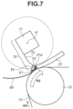
- FIG. 7 is a conceptual diagram illustrating a state where the agitation member of the belt cleaning unit according to the first comparison example pushes toner to a side of a scooping sheet.
- FIG. 8 is a conceptual diagram illustrating a state where the toner pushed by the agitation member of the belt cleaning unit according to the first comparison example leaks from a nip portion between the scooping sheet and the belt.
- FIG. 9 is a conceptual diagram illustrating a positional relationship between the cleaning blade, the agitation member, and the scooping sheet according to the first exemplary embodiment, which also illustrates a state where the agitation member rubbed against the cleaning blade is to be released (restored) from a rubbed state (elastically deformed state).
- FIG. 10 is a conceptual diagram illustrating a positional relationship between the cleaning blade, the agitation member, and the scooping sheet according to the first comparison example.
- FIG. 11 is a conceptual diagram illustrating a positional relationship between the cleaning blade, the agitation member, and the scooping sheet according to the first exemplary embodiment.
- FIG. 12 is a conceptual diagram illustrating a position of a leading end of the scooping sheet according to a first variation example of the first exemplary embodiment.
- FIG. 13 is a conceptual diagram illustrating a position of a leading end of the scooping sheet according to a second comparison example of the first exemplary embodiment.
- FIG. 14 is a conceptual diagram illustrating an example of a mounting condition of the cleaning blade according to the first exemplary embodiment.
- FIG. 15 is a conceptual diagram illustrating another example of the mounting condition of the cleaning blade according to the first exemplary embodiment.
- FIG. 16 is a conceptual diagram illustrating main parts of the belt cleaning unit and the belt of the image forming apparatus according to a second exemplary embodiment of the present disclosure.
- FIG. 17 is a conceptual diagram illustrating a rotational axis settable area of the agitation member according to the second exemplary embodiment.
- FIG. 18 is a conceptual diagram illustrating a cross-sectional view of the belt cleaning unit according to a first variation example of the second exemplary embodiment.
- FIG. 19 is a conceptual diagram illustrating a cross-sectional view of the belt cleaning unit according to a second variation example of the second exemplary embodiment.
- FIGS. 1 to 16 A first exemplary embodiment of the present disclosure will be described with reference to FIGS. 1 to 16 .
- FIG. 1 is a conceptual diagram illustrating an entire body of an image forming apparatus 100 according to the present exemplary embodiment of the present disclosure.
- the image forming apparatus 100 is a tandem-type image forming apparatus which includes a plurality of image forming units a to d.
- a first image forming unit a, a second image forming unit b, a third image forming unit c and a fourth image forming unit d form images with toner (hereinbelow also referred to as developer) of respective colors of yellow (Y), magenta (M), cyan (C), and black (Bk).
- the above-described four units i.e., the first to fourth image forming units a to d are arranged in a row at regular intervals, and configurations of the first to fourth image forming units a to d are substantially similar to each other except for the respective colors of toner stored in the first to fourth image forming units a to d.
- the image forming apparatus 100 according to the present exemplary embodiment will be described by using the first image forming unit a as an example.
- a photosensitive drum 1 a serving as a photosensitive member (image bearing member) includes a metallic cylinder on which a multi-layered functional organic material is laminated.
- the multi-layered functional organic material includes a plurality of layers including a carrier generation layer, which is exposed to light and generates electric charges, and a charge transport layer, which transports the generated electric charges.
- An outermost layer of the plurality of layers has a low electric conductivity and is almost electrically insulated.
- the photosensitive drum 1 a is rotated in a direction of an arrow R 1 indicated in FIG. 1 at a predetermined circumferential speed by a driving force received from a driving power source (not illustrated).
- a charging roller 2 a serving as a charging member is in contact with the photosensitive drum 1 a and uniformly charges a surface of the photosensitive drum 1 a while being rotated with the rotation of the photosensitive drum 1 a in the direction of the arrow R 1 indicated in FIG. 1 .
- a charging power source 20 a applies a direct-current voltage to the charging roller 2 a , and the charging roller 2 a electrically charges the photosensitive drum 1 a by an electric discharge that occurs in minute air gaps on the upstream and downstream sides of a charging portion where the charging roller 2 a is in contact with the photosensitive drum 1 a.
- a development unit 8 a includes a development roller 4 a and a developer application blade 7 a that serve as development members, and a developer storage portion 5 a that stores yellow toner.
- the development roller 4 a is connected to a development power source 21 a .
- a cleaning unit 3 a includes a cleaning blade, which is in contact with the photosensitive drum 1 a , and a waste toner box, which stores toner removed from the photosensitive drum 1 a by the cleaning blade, and collects toner remaining on the photosensitive drum 1 a.
- An exposure unit 11 a includes a scanner unit for laser light scanning using a polygonal mirror, and irradiates the photosensitive drum 1 a with a scanning beam 12 a modulated based on an image signal.
- the photosensitive drum 1 a , the charging roller 2 a , the cleaning unit 3 a , and the development unit 8 a are included in an integrated process cartridge 9 a attachable to and detachable from the image forming apparatus 100 .
- An intermediate transfer belt 13 (i.e., image bearing member) is a rotatable endless belt that bears a toner image (developer).
- the intermediate transfer belt 13 is stretched by three rollers, i.e., a secondary transfer counter roller 15 (hereinafter, called “counter roller 15 ”), a tension roller 14 , and an auxiliary roller 19 , which serve as stretching members.
- the tension roller 14 is urged by a spring (not illustrated) in such a manner that the tension roller 14 maintains a suitable tension with respect to the intermediate transfer belt 13 .
- the counter roller 15 is rotated in a direction of an arrow R 2 indicated in FIG. 1 by receiving a driving force from a driving source (not illustrated). With the rotation of the counter roller 15 , the intermediate transfer belt 13 is moved in a direction of an arrow AA indicated in FIG. 1 , i.e., a rotation and surface movement direction of the intermediate transfer belt 13 .
- the intermediate transfer belt 13 is movable in a forward direction with respect to the photosensitive drums 1 a to 1 d at the substantially uniform speed.
- the auxiliary roller 19 , the tension roller 14 , and the counter roller 15 are grounded electrically.
- the counter roller 15 has an outer diameter of 24.0 mm, and is configured of an aluminum core metal covered with ethylene propylene diene monomer (EPDM) rubber having a thickness of 0.5 mm. Carbon that is used as a conductive agent is scattered on the EPDM rubber in such a manner that electrical resistance of the counter roller 15 is adjusted to approximately 1 ⁇ 10 5 ⁇ .
- EPDM ethylene propylene diene monomer
- a primary transfer roller 10 a is disposed at a position opposite to the photosensitive drum 1 a with the intermediate transfer belt 13 disposed in between the primary transfer roller 10 a and the photosensitive drum 1 a .
- the primary transfer roller 10 a is in contact with an inner circumferential surface of the intermediate transfer belt 13 , and is rotated with the movement of the intermediate transfer belt 13 .
- a secondary transfer roller 25 is disposed at a position opposite to the counter roller 15 with the intermediate transfer belt 13 disposed in between the secondary transfer roller 25 and the intermediate transfer belt 13 , and is in contact with an outer circumferential surface of the intermediate transfer belt 13 . Further, the secondary transfer roller 25 is connected to a secondary transfer power source 26 .
- the image forming operation is started when a control unit (not illustrated), such as a controller, receives an image signal, and the photosensitive drums 1 a to 1 d and the counter roller 15 are rotated at a predetermined circumferential speed (processing speed) by receiving driving force from a driving source (not illustrated).
- processing speed is 200 millimeters per second (mm/s).
- the photosensitive drum 1 a is uniformly charged by the charging roller 2 a to which a voltage having the same polarity as a normal charging polarity of toner (in the present exemplary embodiment, a negative polarity) is applied from the charging power source 20 a . Then, the photosensitive drum 1 a is irradiated with the scanning beam 12 a emitted from the exposure unit 11 a , and an electrostatic latent image according to image information is formed on the photosensitive drum 1 a.
- a voltage having the same polarity as a normal charging polarity of toner in the present exemplary embodiment, a negative polarity
- Toner stored in the development unit 8 a is charged in a negative polarity and applied to the development roller 4 a by the developer application blade 7 a . Then, a predetermined voltage is applied to the development roller 4 a from the development power source 21 a , and the electrostatic latent image is developed with toner at a development portion between the development roller 4 a and the photosensitive drum 1 a , and a toner image corresponding to a yellow image component is formed on the photosensitive drum 1 a.
- the yellow toner image borne on the photosensitive drum 1 a reaches a primary transfer portion N 1 a at which the photosensitive drum 1 a is in contact with the intermediate transfer belt 13 .
- a voltage having a positive polarity is applied to the primary transfer roller 10 a from a primary transfer power source 22 a , and the yellow toner image is primary transferred to the intermediate transfer belt 13 from the photosensitive drum 1 a at the primary transfer portion N 1 a.
- a second color (magenta) toner image, a third color (cyan) toner image, and a fourth color (black) toner image are formed by the second, the third, and the fourth image forming units b, c, and d, respectively, and the toner images are sequentially primary-transferred to the intermediate transfer belt 13 in a manner such that the toner images are superimposed on one another.
- the four-color toner image borne on the intermediate transfer belt 13 is collectively secondary-transferred on a surface of a transfer material P, such as a sheet of paper or an overhead projector (OHP) sheet, when the four-color toner image passes through a secondary transfer portion N 2 at which the secondary transfer roller 25 is in contact with the intermediate transfer belt 13 .
- a voltage having a positive polarity is applied to the secondary transfer roller 25 from the secondary transfer power source 26 , whereby the toner image is secondary-transferred to the transfer material P from the intermediate transfer belt 13 at the secondary transfer portion N 2 .
- the transfer material P is stored in a sheet feeding cassette 16 . After the transfer material P is fed to the conveyance rollers 18 from the sheet feeding cassette 16 , the transfer material P is conveyed to the secondary transfer portion N 2 by conveyance rollers 18 . Then, the transfer material P, on which the four-color toner image is transferred at the secondary transfer portion N 2 , is heated and pressurized by a fixing unit 50 , and four colors of toner are fused, mixed, and fixed to the transfer material P. Then, the transfer material P is discharged from the image forming apparatus 100 and stacked on a discharge tray 52 serving as a stacking unit.
- the belt cleaning unit 30 toner collection unit
- the belt cleaning unit 30 includes a cleaning blade 31 (blade member) in contact with the outer circumferential surface of the intermediate transfer belt 13 at a position opposite to the counter roller 15 .
- the cleaning blade 31 has a free end 31 b that is in contact with the intermediate transfer belt 13 and extends to the upstream side in the rotation direction AA of the intermediate transfer belt 13 , and collects toner from the intermediate transfer belt 13 .
- the image forming apparatus 100 includes a control substrate (not illustrated) on which an electric circuit for controlling operations of each unit of the image forming apparatus 100 is mounted.
- a central processing unit (CPU) (not illustrated) serving as a control unit and a memory (not illustrated) serving as a storage unit for storing various types of control information are mounted on the control substrate.
- the CPU includes one or more processors, circuitry, or combinations thereof, and executes various types of control, such as conveyance control of the transfer material P, driving control of the intermediate transfer belt 13 and the process cartridges 9 , image forming control, and malfunction detection control.
- the intermediate transfer belt 13 is an endless belt member (or a film-like member) including two layers, i.e., a base layer and a surface layer, and having a circumferential length of 700 millimeters (mm).
- the base layer is defined as a layer which is the thickest among the layers of the intermediate transfer belt 13 in the thickness direction of the intermediate transfer belt 13 .
- the base layer has a thickness of 70 micrometers ( ⁇ m).
- the surface layer is a layer formed on the outer circumferential surface of the intermediate transfer belt 13 , and has a thickness of 3 ⁇ m.
- FIG. 2 A is a conceptual diagram illustrating a mounting condition of the cleaning blade 31 of the belt cleaning unit 30 according to the present exemplary embodiment.
- FIG. 2 B is a conceptual diagram illustrating a state where the cleaning blade 31 is mounted.
- FIG. 2 A conceptually illustrates a mounting position of the cleaning blade 31 described below when the cleaning blade 31 is not deformed elastically.
- the belt cleaning unit 30 includes a cleaning container 32 and a cleaning action part 33 disposed in the cleaning container 32 .
- the cleaning container 32 is configured as a part of a frame body of an intermediate transfer unit (not illustrated) which includes the intermediate transfer belt 13 .
- the cleaning action part 33 includes a cleaning blade 31 (blade member) serving as a cleaning member and a supporting member 34 for supporting the cleaning blade 31 .
- the cleaning blade 31 is an elastic blade formed of an elastic material, such as urethane (polyurethane) rubber, and the cleaning blade 31 is adhered to and supported by the supporting member 34 formed of a sheet metal made of a plated steel sheet material.
- an elastic material such as urethane (polyurethane) rubber
- the cleaning blade 31 is a plate-like member having a length in a width direction of the intermediate transfer belt 13 (a lengthwise direction of the cleaning blade 31 ), i.e., a direction intersecting with the moving direction of the intermediate transfer belt 13 indicated by an arrow AA (rotation direction AA).
- the cleaning blade 31 is fixed to the supporting member 34 at the one end in a state where the cleaning blade 31 is viewed in a direction orthogonal to the rotation direction of the intermediate transfer belt 13 .
- another end, i.e., the free end 31 b disposed upstream from the one end in the rotation direction of the intermediate transfer belt 13 is in contact with the intermediate transfer belt 13 .
- the cleaning blade 31 has a length of 240 mm in the lengthwise direction, a thickness of 2 mm, and hardness of 77 degrees according to a standard of JIS K 6253, and may have other configurational dimensions and properties.
- the cleaning action part 33 is swingably disposed with respect to the surface of the intermediate transfer belt 13 .
- the supporting member 34 is swingably supported by a swinging shaft 35 fixed to the cleaning container 32 with respect to the surface of the intermediate transfer belt 13 .
- the supporting member 34 is pressurized by a pressure spring 36 serving as an urging unit disposed inside the cleaning container 32 , and the cleaning action part 33 is able to move about the swinging shaft 35 as a center, and the cleaning blade 31 is urged (pressed) against the intermediate transfer belt 13 .
- the counter roller 15 is disposed on the inner circumference side of the intermediate transfer belt 13 at a position opposite to the cleaning blade 31 .
- the cleaning blade 31 is in contact with the surface of the intermediate transfer belt 13 in an orientation directed opposite to the moving direction of the intermediate transfer belt 13 .
- the cleaning blade 31 is in contact with the surface of the intermediate transfer belt 13 in a state where the free end 31 b in the lateral direction of the cleaning blade 31 faces the upstream side in the moving direction of the intermediate transfer belt 13 .
- a blade nip portion 37 is formed between the cleaning blade 31 and the intermediate transfer belt 13 .
- the cleaning blade 31 scrapes the transfer residual toner from the moving surface of the intermediate transfer belt 13 at the blade nip portion 37 , and stores the collected toner in the cleaning container 32 .
- one portion of the free end 31 b which is in contact with the intermediate transfer belt 13 is referred to as the blade contact end portion 31 c
- another portion on the opposite side of the one portion in the thickness direction, which is not in contact with the intermediate transfer belt 13 is referred to as a blade non-contact end portion 31 d
- one surface of the cleaning blade 31 on which the cleaning blade 31 is in contact with the intermediate transfer belt 13 is referred to as the first side surface 31 e
- another surface opposite to the one surface in the thickness direction is referred to as the second side surface 31 f
- the blade non-contact end portion 31 d is an end portion of the second side surface 31 f on the most upstream side in the rotation direction AA of the intermediate transfer belt 13 .
- a mounting position of the cleaning blade 31 is specified as follows.
- the cleaning blade 31 is mounted on the frame body at a setting angle ⁇ of 22 degrees, a penetration amount ⁇ of 1.3 mm, and an abutting pressure of 0.6 newton centimeters (N/cm).
- the setting angle ⁇ is an angle formed between a tangential line C 1 of the counter roller 15 and the cleaning blade 31 (one surface of the cleaning blade 31 substantially orthogonal to the thickness direction) at an intersection point P 0 of the intermediate transfer belt 13 and the cleaning blade 31 (an edge surface of the free end 31 b of the cleaning blade 31 ), i.e., a position corresponding to the blade contact end portion 31 c .
- the penetration amount ⁇ is a length in the thickness direction by which the cleaning blade 31 overlaps with the counter roller 15 .
- the abutting pressure is defined by a pressing force (linear pressure in the lengthwise direction) from the cleaning blade 31 at the blade nip portion 37 , and is measured by a film type pressure force measurement system (for example, product name: PINCH, manufactured by NITTA Corporation).
- the cleaning blade 31 in contact with the intermediate transfer belt 13 is likely to be turned up at the initial stage because of large friction resistance of when urethane rubber (cleaning blade 31 ) is rubbed against synthetic resin (intermediate transfer belt 13 ).
- an initial lubricant such as graphite fluoride, can previously be applied to the free end 31 b of the cleaning blade 31 .
- the rubber for the cleaning blade 31 have a hardness within a range of 70 degrees or more and 80 degrees or less according to a standard of JIS K 6253. Further, it is also desirable that the abutting pressure of the cleaning blade 31 fall within a range of 0.4 N/cm or more and 0.8 N/cm or less.
- FIG. 3 A is a conceptual diagram illustrating a cross-sectional view of the belt cleaning unit 30 according to the present exemplary embodiment.
- FIG. 3 B is a conceptual diagram illustrating an enlarged main part of the belt cleaning unit 30 .
- FIG. 3 A illustrates an entire body of the belt cleaning unit 30 which also includes the components other than the cleaning blade 31 .
- FIG. 3 B illustrates a configuration in a periphery of a scooping sheet.
- a scooping sheet 60 (sheet member) is disposed on the cleaning container 32 at a position opposite to the cleaning blade 31 .
- the scooping sheet 60 is disposed upstream from the cleaning blade 31 in the rotation direction AA of the intermediate transfer belt 13 , and a free end 61 of the scooping sheet 60 extends toward the downstream side of the rotation direction AA and is in contact with the intermediate transfer belt 13 .
- the scooping sheet 60 is formed of a mylar sheet, and an end portion of the scooping sheet 60 on one side is adhered and fixed to the cleaning container 32 with a double-sided adhesive tape. An unfixed end portion of the scooping sheet 60 on a side opposite to the one side serves as the free end 61 .
- the scooping sheet 60 forms a scooping sheet contact nip 62 where the side of the free end 61 of the scooping sheet 60 is in contact with the intermediate transfer belt 13 .
- An edge surface (edge portion) of the free end 61 of the scooping sheet 60 may form the scooping sheet contact nip 62 by being in contact with the intermediate transfer belt 13 .
- a portion in contact with the intermediate transfer belt 13 may not be the edge surface (edge portion) of the free end 61 of the scooping sheet 60 , and the scooping sheet contact nip 62 may be formed by a side surface in a vicinity of the edge surface of the free end 61 of the scooping sheet 60 .
- the scooping sheet contact nip 62 is formed in an area wider than a lengthwise area of the cleaning blade 31 in the rotation axis direction of the intermediate transfer belt 13 , i.e., the width direction orthogonal to the belt rotation direction.
- the free end 61 of the scooping sheet 60 extends downstream in the rotation direction of the intermediate transfer belt 13 .
- a mylar sheet having a thickness of 50 ⁇ m, a length of 250 mm, and a free length of 5 mm is used as the scooping sheet 60 .
- the scooping sheet 60 is in contact with the intermediate transfer belt 13 with light pressure, and rubes the intermediate transfer belt 13 at the scooping sheet contact nip 62 .
- a gap between the cleaning container 32 and the intermediate transfer belt 13 is eliminated, so that toner leaking out of the cleaning container 32 (frame body) can be reduced or suppressed.
- Toner collected by the cleaning blade 31 is conveyed to a waste toner containing unit (not illustrated) described below.
- FIG. 4 is a conceptual diagram illustrating a state where toner is collected by the cleaning blade 31 according to the present exemplary embodiment.
- toner is accumulated on an upper part of the cleaning blade 31 because the cleaning blade 31 is disposed on the upper side of the intermediate transfer belt 13 . If toner is excessively accumulated on the upper part, a pressure applied to the cleaning blade 31 is increased, which results in occurrence of a cleaning failure caused by spilling of toner out of the cleaning blade 31 and an aggregation of toner on the cleaning blade 31 .
- a conveyance structure to convey toner in the vicinities of the cleaning blade 31 is employed.
- the conveyance structure according to the present exemplary embodiment can be divided into two parts.
- the first part is a mechanism which conveys toner to the second part to prevent toner from being accumulated on the front and the upper parts of the cleaning blade 31 .
- the second part is a mechanism which conveys toner conveyed from the first part to the waste toner containing unit (not illustrated) disposed outside the cleaning container 32 .
- the first part of the conveyance structure is configured of the agitation member 70 .
- the agitation sheet 72 is mounted on the rotation shaft 71 and rotated together with the rotation shaft 71 . Further, the agitation sheet 72 comes into contact with the second side surface 31 f of the cleaning blade 31 on the side opposite to the first side surface 31 e that is in contact with the intermediate transfer belt 13 .
- the agitation member 70 includes the rotation shaft 71 (shaft portion) interlocking with a driving source and the agitation sheet 72 (sheet portion) fixed to the rotation shaft 71 .
- One end of the agitation sheet 72 is adhered and fixed to one surface of the rotation shaft 71 with a double-sided adhesive tape.
- one end portion of the agitation sheet 72 is fixed to the rotation shaft 71 with the double-sided adhesive tape, and another end portion of the agitation sheet 72 serves as a free end 73 (also called “a free end 73 of the agitation member 70 ”).
- the agitation sheet 72 is adhered to the rotation shaft 71 in such a manner that the free end 73 extends in a direction in which a force from the upstream side to the downstream side in the rotation direction of the rotation shaft 71 acts on the agitation sheet 72 and the agitation sheet 72 is pressed against the double-sided adhesive tape.
- coming-off of the agitation sheet 72 from the double-sided adhesive tape can be prevented when the agitation member 70 receives force (reactive force) from toner conveyed by the agitation member 70 .
- the agitation member 70 interlocks with a driving source of a process unit of the image forming apparatus 100 , and is rotated at a rotation speed of 3 turns (cycles) per second.
- the agitation member 70 can have a width not longer than or equal to the length of the cleaning blade 31 in the lengthwise direction, as long as the width of the agitation member 70 is wider than a printing area corresponding to a residual toner remaining area where toner is remained when normal printing is executed.
- the rotation shaft 71 is configured of a rectangular parallelepiped member having a 2-millimeter-square at a cross-sectional surface orthogonal to an axis direction and a length of 225 mm that is equal to or longer than a length of the printing area or a length of the agitation sheet 72 described below.
- a mylar sheet is used for the agitation sheet 72 , and the agitation sheet 72 has a width of 220 mm, i.e., a width greater than or equal to the width of a printing area of a letter-size sheet.
- the agitation sheet 72 has a free length of 4 mm from the rotation shaft 71 , which is long enough to cause the agitation sheet 72 to come into contact with the cleaning blade 31 .
- the agitation member 70 Since the agitation member 70 is rotated in the same direction as the rotation direction of the intermediate transfer belt 13 , in the vicinity of the cleaning blade 31 , the free end 73 of the agitation member 70 is moved in a direction opposite to the surface movement direction of the intermediate transfer belt 13 .
- the agitation member 70 If the agitation member 70 is rotated in a direction opposite to the rotation direction of the intermediate transfer belt 13 , in a vicinity of the cleaning blade 31 , the agitation member 70 conveys toner from the free end 31 b of the cleaning blade 31 toward a fixed end of the cleaning blade 31 . In this case, there is a risk that the free end 73 of the agitation member 70 comes into contact with the free end 31 b of the cleaning blade 31 which serves as a collection surface for residual toner collection. Consequently, an impact of the contact between the toner conveyed by the agitation member 70 or the free end 73 of the agitation member 70 and the cleaning blade 31 likely results in a cleaning failure. Thus, in the present exemplary embodiment, the agitation member 70 is rotated in the same direction as the rotation direction of the intermediate transfer belt 13 .
- the agitation member 70 conveys toner to the second part (not illustrated) of the conveyance structure to prevent toner to be accumulated at a predetermined amount or more on the upper part of the scooping sheet 60 or the cleaning blade 31 .
- toner conveyance from the first part (agitation member 70 ) to the second part of the conveyance structure will be described with reference to FIGS. 5 A and 5 B .
- FIGS. 5 A and 5 B are conceptual diagrams each illustrating a toner conveyance state in the rotation of the agitation member 70 according to the present exemplary embodiment.
- FIG. 5 A illustrates a state where the agitation member 70 conveys toner upward.
- the agitation member 70 rubes against the inner wall surface of the cleaning container 32 .
- a distance from a rotation axis center of the agitation member 70 to the inner wall surface of the cleaning container 32 is 5 mm
- the free length of the agitation sheet 72 is designed in such a manner that a distance from the rotation center to the leading end of the agitation sheet 72 is more than 5 mm.
- FIG. 5 B illustrates a state immediately after the agitation member 70 is released (elastically restored) from a contact state (flexibly deformed state) with respect to the inner wall surface.
- toner conveyed upward by the agitation member 70 is flicked by a restoration force of when the agitation member 70 in contact with the inner wall surface of the cleaning container 32 is released from the contact state.
- the flicked toner is conveyed to the waste toner containing unit (not illustrated) arranged on the outside of the cleaning container 32 by the second part of the conveyance structure.
- the second part of the conveyance structure includes a screw member 75 .
- the screw member 75 is disposed in an area to which the flicked toner is conveyed when the agitation member 70 is released from the contact state.
- the screw member 75 having a spiral-shape is also rotated in conjunction with the driving source of the process unit. Toner conveyed by the agitation member 70 is further conveyed by the screw member 75 to an end portion on one side in the width direction of the intermediate transfer belt 13 which is orthogonal to the rotation direction of the intermediate transfer belt 13 .
- the screw member 75 conveys toner to the outside of the cleaning container 32 in a depth direction in FIG. 3 A .
- the toner is then further conveyed to the waste toner containing unit (not illustrated) using a different conveyance member (not illustrated).
- the above-described conveyance structure conveys toner collected by the cleaning blade 31 to the outside of the cleaning container 32 , and further conveys to the waste toner container unit (not illustrated).
- FIG. 6 is a conceptual diagram illustrating a state of toner collected by the belt cleaning unit 30 according to the first comparison example of the present exemplary embodiment.
- FIG. 6 illustrates a state where toner is collected by the scooping sheet 60 and the cleaning blade 31 of the first comparison example.
- the scooping sheet 60 is disposed to reduce or suppress leakage of toner inside the cleaning container 32 .
- the scooping sheet 60 is disposed in such a manner that the free end 61 of the scooping sheet 60 faces toward the cleaning blade 31 .
- FIG. 7 is a conceptual diagram illustrating a state where the agitation member 70 included in the belt cleaning unit 30 according to the first comparison example pushes toner to a side of the scooping sheet 60 .
- FIG. 8 is a conceptual diagram illustrating a state where the toner pushed by the agitation member 70 of the belt cleaning unit 30 according to the first comparison example leaks out of a nip portion between the scooping sheet 60 and the intermediate transfer belt 13 .
- FIG. 7 illustrates a state where toner on the cleaning blade 31 is conveyed by the agitation member 70 .
- toner is slipped out of the scooping sheet 60 and drops downward as illustrated in FIG. 8 .
- the agitation member 70 conveys toner while being in contact with the upper part of the cleaning blade 31 , when the free end 73 of the agitation member 70 is released from the upper part of the cleaning blade 31 , the toner is flicked by a force caused by the agitation member 70 being released.
- toner is strongly flicked toward the scooping sheet 60 from the blade non-contact end portion 31 d when the agitation member 70 is released from the free end 31 b of the cleaning blade 31 .
- toner is pushed in a direction of an arrow F 1 .
- Leaking of toner out of the scooping sheet 60 of the cleaning container 32 leads to occurrence of image defects caused by contamination of the secondary transfer roller 25 due to toner scattered on the secondary transfer portion N 2 or adhesion of toner to the transfer material P passing through the secondary transfer portion N 2 .
- toner dripping a phenomenon in which toner leaks out of the scooping sheet 60 of the cleaning container 32 is called “toner dripping”.
- the free end 61 of the scooping sheet 60 hardly receive the force of the agitation member 70 pushing toner, an amount of toner pushed by the agitation member 70 and leaking out of the scooping sheet 60 can be reduced, whereby occurrence of image defects caused by the toner dripping is reduced or suppressed.
- FIG. 9 is a conceptual diagram illustrating a positional relationship between the cleaning blade 31 , the agitation member 70 , and the scooping sheet 60 according to the present exemplary embodiment, which also illustrates a state where the agitation member 70 rubbing the cleaning blade 31 is to be released (restored) from a rubbing state (elastically deformed state).
- FIG. 9 illustrates a minute change occurring at a timing of when the free end 73 of the agitation member 70 is separated from the cleaning blade 31 .
- the agitation member 70 is rotated about a rotation center K (axial center position) serving as a rotation axis.
- a pushing force along a tangential line direction of the blade non-contact end portion 31 d becomes the greatest when the free end 73 of the agitation member 70 is separated (released) from the blade non-contact end portion 31 d of the cleaning blade 31 .
- FIG. 9 illustrates a state immediately before and immediately after the free end 73 of the agitation member 70 is separated from the blade non-contact end portion 31 d .
- the free end 73 of the agitation member 70 immediately before the separation is indicated by a solid line, and the free end 73 immediately after the separation is indicated by a dashed line.
- the moving direction of the free end 73 of the agitation member 70 from a state immediately before the separation to a state immediately after the separation, by the rotation operation, is a direction along a second imaginary line (imaginary line B) which is passing through the blade non-contact end portion 31 d .
- the imaginary line B is orthogonal to a first imaginary line (imaginary line A) which is connecting the rotation center K and the blade non-contact end portion 31 d.
- FIG. 10 is a conceptual diagram illustrating a positional relationship between the cleaning blade 31 , the agitation member 70 , and the scooping sheet 60 according to the first comparison example of the present exemplary embodiment.
- the free end 61 of the scooping sheet 60 is disposed in such a manner that the free end 61 is in a position closer to the cleaning blade 31 than an intersection point P 1 (intersecting position) where the imaginary line B intersects with the intermediate transfer belt 13 .
- the free end 61 of the scooping sheet 60 is at a position between the intersection point P 1 and the free end 31 b of the cleaning blade 31 in the rotation direction of the intermediate transfer belt 13 .
- the free end 61 of the scooping sheet 60 is disposed at a position away from the cleaning blade 31 than the intersection point P 1 .
- the intersection point P 1 is disposed at a position between the free end 61 of the scooping sheet 60 and the free end 31 b of the cleaning blade 31 in the rotation direction of the intermediate transfer belt 13 .
- the free end 61 of the scooping sheet 60 receives the force of pushing toner, and the toner dripping occurs as a result.
- the setting position of the scooping sheet 60 is appropriately designed to reduce or suppress the toner dripping caused by the force in the pushing direction.
- the toner dripping occurs when the force of the agitation member 70 pushing toner is exerted on the free end 61 of the scooping sheet 60 .
- the force of pushing toner is hardly exerted on the free end 61 of the scooping sheet 60 .
- the free end 61 of the scooping sheet 60 is disposed at a position between the intersection point P 1 and the free end 31 b of the cleaning blade 31 .
- FIG. 11 is a conceptual diagram illustrating a positional relationship between the cleaning blade 31 , the agitation member 70 , and the scooping sheet 60 according to the present exemplary embodiment.
- FIG. 11 specifically illustrates a distance W 2 between the free end 61 of the scooping sheet 60 and the free end 31 b of the cleaning blade 31 .
- the force exerted on toner can be obtained by drawing the imaginary line A (line orthogonal to the imaginary line A) connecting the rotation center K and the blade non-contact end portion 31 d , and then drawing the imaginary line B which is a vertical line of the imaginary line A and passes through the blade non-contact end portion 31 d.
- the cleaning blade 31 acts as a wall when the agitation member 70 pushes the toner.
- the free end 61 of the scooping sheet 60 is disposed at a position closer to the cleaning blade 31 than the intersection point P 1 where the imaginary line B intersects with the intermediate transfer belt 13 .
- the free end 61 of the scooping sheet 60 in a case where the free end 61 of the scooping sheet 60 is disposed at a position closer to the cleaning blade 31 than the intersection point P 1 , the free end 61 can be disposed at a position that is between the intersection point P 1 and the free end 31 b of the cleaning blade 31 and is closer to the cleaning blade 31 than to the intersection point P 1 .
- the scooping sheet 60 is disposed upstream from the cleaning blade 31 in the rotation direction of the intermediate transfer belt 13 , whereby the scooping sheet 60 does not come into contact with the cleaning blade 31 .
- a distance W 2 between the free end 61 of the scooping sheet 60 and the cleaning blade 31 is set to a value of fifty times or more of a toner size (average grain size K) (W 2 ⁇ 50 ⁇ K 1 ). More desirably, the distance W 2 is set to a value of seventy times or more of the toner size.
- a toner size (average grain size) is 7 ⁇ m. Accordingly, the distance W 2 between the cleaning blade 31 and the free end 61 of the scooping sheet 60 can be set to 0.35 mm or more. More desirably, the distance W 2 is set to 0.49 mm or more.
- FIG. 12 is a conceptual diagram illustrating a position of a leading end of the scooping sheet 60 according to the first variation example of the present exemplary embodiment.
- FIG. 13 is a conceptual diagram illustrating a position of a leading end of the scooping sheet 60 according to a second comparison example with respect to the first variation example of the present exemplary embodiment.
- toner may likely be accumulated on a front part of the scooping sheet 60 and the cleaning blade 31 .
- cleaning failure may occur in the cleaning blade 31 .
- the scooping sheet 60 is lifted up by the toner, and a possibility of occurrence of the toner dripping is increased.
- the toner dripping is less likely to occur if toner collected by the cleaning blade 31 can pass through a gap between the scooping sheet 60 and the cleaning blade 31 .
- the toner dripping can be reduced or suppressed with the configuration having an appropriate gap (distance W 2 ) described in the first variation example of the present disclosure illustrated in FIG. 12 .
- toner particles are likely to collide with each other and hardly pass through the gap.
- a gap between the scooping sheet 60 and the cleaning blade 31 is set to a value greater than zero, i.e., the free end 61 of the scooping sheet 60 is disposed upstream from the free end 31 b of the cleaning blade 31 , occurrence of the toner dripping is reduced or suppressed.
- a gap (distance W 2 ) to a value of fifty times or more of a toner size (an average grain size of the toner particle)
- a significant effect can be acquired with respect to the above described issues.
- the positional relationship is configured in such a manner that a relationship W 2 ⁇ 50 ⁇ K 1 is satisfied when the average grain size of a toner particle is K 1 .
- the scooping sheet 60 and the cleaning blade 31 are disposed with a gap of a predetermined distance or more.
- an imaginary line connecting a position of the end portion (blade non-contact end portion 31 d ) on the most upstream side of the second side surface 31 f in the direction of the arrow R 2 (rotation direction AA) of the intermediate transfer belt 13 and the axial center position K of the rotation shaft 71 can be specified as the first imaginary line A.
- an imaginary line, which is orthogonal to the first imaginary line A, passing through a position of the end portion (blade non-contact end portion 31 d ) on the most upstream side of the second side surface 31 f can be specified as the second imaginary line B.
- the free end 61 of the scooping sheet 60 is disposed at a position closer to the free end 31 b of the cleaning blade 31 than the intersection position (intersection point) P 1 where the second imaginary line B intersects with the outer circumferential surface of the intermediate transfer belt 13 .
- the free end 61 of the scooping sheet 60 can be disposed at a position away from the cleaning blade 31 by the distance W 2 having a value of fifty times or more of the toner size. In this way, the force of the agitation member 70 pushing toner is hardly exerted on the free end 61 of the scooping sheet 60 , whereby the toner dripping from the scooping sheet 60 can be reduced or suppressed more efficiently.
- a thickness from the blade contact end portion 31 c to the blade non-contact end portion 31 d of the free end 31 b is the thickness W 1 (in the present exemplary embodiment, the thickness W 1 is 2 mm), and the cleaning blade 31 acts as a wall standing in a path of the agitation member 70 .
- the agitation member 70 hardly reaches a region in a vicinity of the cleaning blade 31 .
- the agitation member 70 hardly reaches the region within the thickness W 1 of the cleaning blade 31 .
- a distance between the scooping sheet 60 and the cleaning blade 31 is set to a value equal to or less than the thickness of the cleaning blade 31 .
- the distance W 2 between the cleaning blade 31 and the scooping sheet 60 is set to a value of fifty times or more of the toner size and equal to or less than the thickness W 1 of the cleaning blade 31 .
- the axial center position K of the rotation shaft 71 in the in-use posture can be disposed on the upper side of the end portion (blade non-contact end portion 31 d ) on the most upstream side of the second side surface 31 f in a gravity direction G.
- the force of the agitation member 70 pushing toner is applied from the upper side in the gravity direction G, it is expected that a risk of image defects is high in comparison to the case where the force is not applied or hardly applied from the upper side in the gravity direction G.
- a risk of image defects can sufficiently be reduced by disposing the free end 61 of the scooping sheet 60 at a position closer to the free end 31 b of the cleaning blade 31 than the intersection point P 1 .
- the axial center position K of the rotation shaft 71 is disposed on the same side of the scooping sheet 60 in a state where the respective constituent elements are viewed from a direction parallel to the rotation axis direction of the rotation shaft 71 .
- the toner dripping can be sufficiently reduced by the configuration having the free end 61 of the scooping sheet 60 at a position closer to the free end 31 b of the cleaning blade 31 than the intersection point P 1 .
- the shortest distance between the axial center position K of the rotation shaft 71 and the free end 61 of the scooping sheet 60 in the in-use posture can be specified as W 3 , in a state where the respective constituent elements are viewed in a direction parallel to the rotation axis direction of the rotation shaft 71 .
- a distance PS between the intersection point P 1 and the cleaning blade 31 is set to 3.5 mm.
- the distance W 2 between the free end 61 of the scooping sheet 60 and the cleaning blade 31 is 0.2 mm.
- the distance W 2 is 0.4 mm.
- FIG. 14 is a conceptual diagram illustrating an example of a mounting condition of the cleaning blade 31 according to the present exemplary embodiment.
- FIG. 15 is a conceptual diagram illustrating another example of the mounting condition of the cleaning blade 31 according to the present exemplary embodiment.
- the mounting angle of the cleaning blade 31 in the in-use posture can optionally be set within a range of ⁇ 45 degrees (see FIG. 14 ) to +45 degrees (see FIG. 15 ) with respect to the horizontal direction. In other words, at the mounting angle between ⁇ 45 degrees to +45 degrees, collected toner is accumulated on the upper part of the cleaning blade 31 .
- the blade contact end portion 31 c on the most upstream side of the first side surface 31 e of the cleaning blade 31 is in contact with the intermediate transfer belt 13 in the direction of the arrow R 2 (rotation direction AA) of the intermediate transfer belt 13 .
- An angle AG formed by the tangential line C 1 of the intermediate transfer belt 13 and a horizontal line H 1 at a contact point (blade contact end portion 31 c ) between the blade contact end portion 31 c on the most upstream side of the first side surface 31 e and the intermediate transfer belt 13 can be set to 45 degrees or less.
- the agitation member 70 is disposed in a vicinity of the cleaning blade 31 , and toner can be conveyed in the lengthwise direction.
- an amount of toner accumulated on the upper part of the cleaning blade 31 can be reduced. Accordingly, excessive rise of pressure applied to the intermediate transfer belt 13 disposed below the cleaning blade 31 is reduced or suppressed, and the cleaning performance of the cleaning blade 31 can be improved.
- a position of the free end 61 of the scooping sheet 60 can also be set similarly to the first exemplary embodiment illustrated in FIG. 3 A .
- the rotation shaft 71 of the agitation member 70 is disposed on the upper left side of the blade non-contact end portion 31 d .
- the rotation shaft 71 can be disposed at a position different from the position illustrated in FIG. 3 A .
- FIG. 16 is a conceptual diagram illustrating main parts of the belt cleaning unit 30 and the intermediate transfer belt 13 of the image forming apparatus 100 according to the present exemplary embodiment of the present disclosure.
- a thickness from the blade contact end portion 31 c to the blade non-contact end portion 31 d of the free end 31 b is the thickness W 1
- the cleaning blade 31 acts as a wall standing in a path of the agitation member 70 . Consequently, the agitation member 70 hardly reaches a region Rs in the vicinity of the cleaning blade 31 . In other words, the agitation member 70 hardly reaches the region within the thickness W 1 of the cleaning blade 31 .
- a distance between the scooping sheet 60 and the cleaning blade 31 can be set to a value equal to or less than the thickness of the cleaning blade 31 .
- the distance W 2 between the cleaning blade 31 and the scooping sheet 60 is set to a value of fifty times or more of the toner size and equal to or less than the thickness W 1 of the cleaning blade 31 to reduce or suppress occurrence of image defects more efficiently.
- the image forming apparatus 100 includes the intermediate transfer belt 13 , the cleaning blade 31 , the scooping sheet 60 , and the agitation member 70 .
- the intermediate transfer belt 13 is a rotatable endless belt which bears a toner image.
- the cleaning blade 31 has the free end 31 b and collects toner from the intermediate transfer belt 13 .
- the free end 31 b is in contact with the intermediate transfer belt 13 and extends upstream in the rotation direction AA of the intermediate transfer belt 13 .
- the scooping sheet 60 is disposed upstream from the cleaning blade 31 in the direction of the arrow R 2 (rotation direction AA) of the intermediate transfer belt 13 , and the free end 61 of the scooping sheet 60 extends toward the downstream side and is in contact with the intermediate transfer belt 13 .
- the agitation sheet 72 that is elastically deformable is mounted on the rotation shaft 71 and rotated together with the rotation shaft 71 .
- the agitation sheet 72 comes into contact with the second side surface 31 f of the cleaning blade 31 disposed on the opposite side of the first side surface 31 e which is in contact with the intermediate transfer belt 13 . Then, the agitation sheet 72 can come into contact with the blade non-contact end portion 31 d on the most upstream side of the second side surface 31 f in the direction of the arrow R 2 (rotation direction AA) of the intermediate transfer belt 13 .
- the present exemplary embodiment can achieve the effect similar to the effect achieved by the first exemplary embodiment.
- the agitation member 70 in a configuration in which the agitation member 70 is disposed in a vicinity of the cleaning blade 31 and the scooping sheet 60 , it is possible to reduce toner leaking to the outside during the rotation of the agitation member 70 .
- the rotation shaft 71 of the agitation member 70 is disposed on the upper left side of the blade non-contact end portion 31 d .
- the rotation shaft 71 can be disposed at a position different from the position illustrated in FIG. 16 .
- the configuration of the agitation member 70 may be any configuration as long as toner is scraped by the agitation member 70 coming into contact with the upper part of the cleaning blade 31 .
- the rotation shaft 71 can be set in an area illustrated in FIG. 17 .
- FIG. 17 is a conceptual diagram illustrating a rotation shaft mounting (mountable) area of the agitation member 70 according to the present exemplary embodiment.
- FIGS. 18 and 19 are conceptual diagrams illustrating cross-sectional views of the belt cleaning unit 30 according to the first and the second variation examples of the present exemplary embodiment.
- FIG. 17 illustrates a settable position where the rotation shaft 71 can be disposed.
- FIG. 18 or 19 illustrates a position of the rotation shaft 71 .
- an imaginary line which is parallel to the tangential line C 1 of the intermediate transfer belt 13 at a contact position of the intermediate transfer belt 13 and the blade contact end portion 31 c and passes through the blade non-contact end portion 31 d , is specified as an imaginary line C (third imaginary line).
- an imaginary line which extends in a direction parallel to a surface direction of a surface of the supporting member 34 to which the second side surface 31 f of the cleaning blade 31 is fixed and passes through a contact position of the fixed end 31 a of the cleaning blade 31 and the supporting member 34 is specified as an imaginary line D (fourth imaginary line).
- the rotation shaft 71 can be disposed in an area opposite to a side of the intermediate transfer belt 13 .
- an imaginary line which is parallel to the tangential line C 1 of the intermediate transfer belt 13 at the contact position of the cleaning blade 31 and the intermediate transfer belt 13 and passes through the blade non-contact end portion 31 d on the most upstream side of the second side surface 31 f , is specified as the third imaginary line C.
- an imaginary line which extends in a direction parallel to a surface direction of a surface of the supporting member 34 for supporting the cleaning blade 31 to which the second side surface 31 f of the cleaning blade 31 is fixed and passes through a contact position of the fixed end 31 a of the cleaning blade 31 and the supporting member 34 , is specified as the fourth imaginary line D.
- the rotation shaft 71 can be disposed in an area on a side opposite to the intermediate transfer belt 13 .
- the vertical line G 1 which passes through a position of the end portion (blade contact end portion 31 c ) on the most upstream side of the first side surface 31 e , in a state where the respective constituent elements in the in-use posture are viewed in the rotation axis direction of the rotation shaft 71 . Then, with respect to the vertical line G 1 , the axial center position K of the rotation shaft 71 can be disposed on the same side of the scooping sheet 60 .
- the vertical line G 1 which passes through a position of the end portion (blade contact end portion 31 c ) on the most upstream side of the first side surface 31 e , in a state where the respective constituent elements in the in-use posture are viewed in the rotation axis direction of the rotation shaft 71 . Then, with respect to the vertical line G 1 , the axial center position K of the rotation shaft 71 can be disposed on the opposite side of the scooping sheet 60 .
- the agitation member 70 which is in the rotation operation and rubs the second side surface 31 f of the cleaning blade 31 is separated from the blade non-contact end portion 31 d , the agitation member 70 is likely to push toner to the outside.
- the rotation shaft 71 is disposed in the rotational axis settable area, even in a case where the scooping sheet 60 rubs the second side surface 31 f of the cleaning blade 31 , it is possible to reduce the amount of toner pushed by the agitation member 70 and to prevent the toner from flowing toward the free end 61 of the scooping sheet 60 . As a result, it is possible to reduce or suppress leakage of toner.
Landscapes
- Physics & Mathematics (AREA)
- General Physics & Mathematics (AREA)
- Electrostatic Charge, Transfer And Separation In Electrography (AREA)
- Cleaning In Electrography (AREA)
Abstract
Description
| TABLE 1 | ||
| Distance W2 between Free | ||
| End of Scooping Sheet and | ||
| Free End of Cleaning | ||
| Blade (Distance PS between | Toner | |
| Intersection Point P1 and | Leakage | |
| Free End of Cleaning Blade | (Toner | |
| is 3.5 mm (PS = 3.5 mm)) | Dripping) | |
| First Exemplary | 2 mm (<PS; >0.49 mm) | ○ |
| Embodiment | ||
| First Variation Example | 0.2 mm (>0; <0.35 mm < PS) | ▴ |
| of First Exemplary | ||
| Embodiment (First | ||
| Experimental Example) | ||
| First Variation Example | 0.4 mm (>0; >0.35 mm; | ● |
| of First Exemplary | <0.49 mm < PS) | |
| Embodiment (Second | ||
| Experimental Example) | ||
| First Comparison | 4 mm (>PS) | x |
| Example | ||
| Second Comparison | 0 (Contact State) | x |
| Example | ||
<Relationship between Distance from Scooping Sheet to Cleaning Blade and Dripping Toner>
Claims (15)
Applications Claiming Priority (2)
| Application Number | Priority Date | Filing Date | Title |
|---|---|---|---|
| JP2022025370A JP2023121972A (en) | 2022-02-22 | 2022-02-22 | image forming device |
| JP2022-025370 | 2022-02-22 |
Publications (2)
| Publication Number | Publication Date |
|---|---|
| US20230266705A1 US20230266705A1 (en) | 2023-08-24 |
| US12061434B2 true US12061434B2 (en) | 2024-08-13 |
Family
ID=87573935
Family Applications (1)
| Application Number | Title | Priority Date | Filing Date |
|---|---|---|---|
| US18/166,937 Active US12061434B2 (en) | 2022-02-22 | 2023-02-09 | Image forming apparatus to reduce or suppress leakage of toner |
Country Status (2)
| Country | Link |
|---|---|
| US (1) | US12061434B2 (en) |
| JP (1) | JP2023121972A (en) |
Citations (3)
| Publication number | Priority date | Publication date | Assignee | Title |
|---|---|---|---|---|
| JP2003223085A (en) | 2002-01-30 | 2003-08-08 | Canon Inc | Cleaning device and image forming apparatus provided with the same |
| JP2021076823A (en) | 2019-10-31 | 2021-05-20 | キヤノン株式会社 | Cleaning device and image forming apparatus |
| JP2021086092A (en) * | 2019-11-29 | 2021-06-03 | キヤノン株式会社 | Image forming apparatus |
Family Cites Families (7)
| Publication number | Priority date | Publication date | Assignee | Title |
|---|---|---|---|---|
| JPH07140869A (en) * | 1993-11-22 | 1995-06-02 | Fuji Xerox Co Ltd | Image forming device |
| JP2000235336A (en) * | 1999-02-16 | 2000-08-29 | Konica Corp | Image forming device and cleaning device |
| JP2005055789A (en) * | 2003-08-07 | 2005-03-03 | Canon Inc | Cleaning means and process cartridge |
| JP2005300801A (en) * | 2004-04-09 | 2005-10-27 | Konica Minolta Business Technologies Inc | Image forming apparatus |
| JP4807114B2 (en) * | 2006-03-14 | 2011-11-02 | 富士ゼロックス株式会社 | Cleaner device |
| JP2012128373A (en) * | 2010-12-17 | 2012-07-05 | Canon Finetech Inc | Cleaning device and image forming apparatus |
| US11209766B2 (en) * | 2019-10-31 | 2021-12-28 | Canon Kabushiki Kaisha | Cleaning device and image forming apparatus |
-
2022
- 2022-02-22 JP JP2022025370A patent/JP2023121972A/en active Pending
-
2023
- 2023-02-09 US US18/166,937 patent/US12061434B2/en active Active
Patent Citations (3)
| Publication number | Priority date | Publication date | Assignee | Title |
|---|---|---|---|---|
| JP2003223085A (en) | 2002-01-30 | 2003-08-08 | Canon Inc | Cleaning device and image forming apparatus provided with the same |
| JP2021076823A (en) | 2019-10-31 | 2021-05-20 | キヤノン株式会社 | Cleaning device and image forming apparatus |
| JP2021086092A (en) * | 2019-11-29 | 2021-06-03 | キヤノン株式会社 | Image forming apparatus |
Also Published As
| Publication number | Publication date |
|---|---|
| US20230266705A1 (en) | 2023-08-24 |
| JP2023121972A (en) | 2023-09-01 |
Similar Documents
| Publication | Publication Date | Title |
|---|---|---|
| US7460811B2 (en) | Image forming apparatus | |
| JP2008003445A (en) | Image forming apparatus | |
| JP2006018177A (en) | Image forming apparatus | |
| US20130287450A1 (en) | Developing device, process cartridge, and image forming apparatus | |
| US20220342349A1 (en) | Developing device, and image forming apparatus including the same | |
| US7480470B2 (en) | Image forming apparatus including a removing member for removing toner from a toner collecting member | |
| US12061434B2 (en) | Image forming apparatus to reduce or suppress leakage of toner | |
| JP2011033761A (en) | Image forming apparatus | |
| JP2022059719A (en) | Image forming device | |
| US20230408947A1 (en) | Image forming apparatus | |
| US9864305B2 (en) | Image forming apparatus | |
| JP2016006491A (en) | Image forming apparatus | |
| US11294300B2 (en) | Development device and image forming apparatus including the development device | |
| US12298685B2 (en) | Image forming apparatus for maintaining cleaning performance while preventing turn-over of a contact member | |
| JP2018180394A (en) | Image forming device | |
| JPH04133084A (en) | Transfer device | |
| US10990055B2 (en) | Image forming apparatus including a conveyance guide for guiding a recording medium conveyed from a registration roller pair to a transfer nip | |
| CN108255030B (en) | Image forming apparatus and image forming method | |
| US12111584B2 (en) | Image forming apparatus with charge eliminating needle protection cover that maintains constant interval between the needle and a sheet | |
| JP3940654B2 (en) | Fixing device and image forming apparatus | |
| JPH11272135A (en) | Image forming device | |
| US11526095B2 (en) | Image forming apparatus including detachable development device | |
| US20240255863A1 (en) | Static elimination apparatus and image forming apparatus | |
| JPS597660A (en) | Sheet conveyance device | |
| JP2020086012A (en) | Image forming device |
Legal Events
| Date | Code | Title | Description |
|---|---|---|---|
| FEPP | Fee payment procedure |
Free format text: ENTITY STATUS SET TO UNDISCOUNTED (ORIGINAL EVENT CODE: BIG.); ENTITY STATUS OF PATENT OWNER: LARGE ENTITY |
|
| AS | Assignment |
Owner name: CANON KABUSHIKI KAISHA, JAPAN Free format text: ASSIGNMENT OF ASSIGNORS INTEREST;ASSIGNOR:ISHIO, SHOHEI;REEL/FRAME:062898/0119 Effective date: 20230125 |
|
| STPP | Information on status: patent application and granting procedure in general |
Free format text: DOCKETED NEW CASE - READY FOR EXAMINATION |
|
| STPP | Information on status: patent application and granting procedure in general |
Free format text: NON FINAL ACTION MAILED |
|
| STPP | Information on status: patent application and granting procedure in general |
Free format text: RESPONSE TO NON-FINAL OFFICE ACTION ENTERED AND FORWARDED TO EXAMINER |
|
| STPP | Information on status: patent application and granting procedure in general |
Free format text: NOTICE OF ALLOWANCE MAILED -- APPLICATION RECEIVED IN OFFICE OF PUBLICATIONS |
|
| STPP | Information on status: patent application and granting procedure in general |
Free format text: PUBLICATIONS -- ISSUE FEE PAYMENT VERIFIED |
|
| STCF | Information on status: patent grant |
Free format text: PATENTED CASE |