US12061237B2 - Detecting whether a battery management system is abnormal - Google Patents
Detecting whether a battery management system is abnormal Download PDFInfo
- Publication number
- US12061237B2 US12061237B2 US17/204,759 US202117204759A US12061237B2 US 12061237 B2 US12061237 B2 US 12061237B2 US 202117204759 A US202117204759 A US 202117204759A US 12061237 B2 US12061237 B2 US 12061237B2
- Authority
- US
- United States
- Prior art keywords
- time
- time period
- measured
- control unit
- capacitor
- Prior art date
- Legal status (The legal status is an assumption and is not a legal conclusion. Google has not performed a legal analysis and makes no representation as to the accuracy of the status listed.)
- Active, expires
Links
Images


Classifications
-
- G—PHYSICS
- G01—MEASURING; TESTING
- G01R—MEASURING ELECTRIC VARIABLES; MEASURING MAGNETIC VARIABLES
- G01R31/00—Arrangements for testing electric properties; Arrangements for locating electric faults; Arrangements for electrical testing characterised by what is being tested not provided for elsewhere
- G01R31/36—Arrangements for testing, measuring or monitoring the electrical condition of accumulators or electric batteries, e.g. capacity or state of charge [SoC]
- G01R31/3644—Constructional arrangements
- G01R31/3648—Constructional arrangements comprising digital calculation means, e.g. for performing an algorithm
-
- H—ELECTRICITY
- H01—ELECTRIC ELEMENTS
- H01M—PROCESSES OR MEANS, e.g. BATTERIES, FOR THE DIRECT CONVERSION OF CHEMICAL ENERGY INTO ELECTRICAL ENERGY
- H01M10/00—Secondary cells; Manufacture thereof
- H01M10/42—Methods or arrangements for servicing or maintenance of secondary cells or secondary half-cells
- H01M10/425—Structural combination with electronic components, e.g. electronic circuits integrated to the outside of the casing
- H01M10/4264—Structural combination with electronic components, e.g. electronic circuits integrated to the outside of the casing with capacitors
-
- G—PHYSICS
- G01—MEASURING; TESTING
- G01R—MEASURING ELECTRIC VARIABLES; MEASURING MAGNETIC VARIABLES
- G01R31/00—Arrangements for testing electric properties; Arrangements for locating electric faults; Arrangements for electrical testing characterised by what is being tested not provided for elsewhere
- G01R31/36—Arrangements for testing, measuring or monitoring the electrical condition of accumulators or electric batteries, e.g. capacity or state of charge [SoC]
- G01R31/382—Arrangements for monitoring battery or accumulator variables, e.g. SoC
- G01R31/3835—Arrangements for monitoring battery or accumulator variables, e.g. SoC involving only voltage measurements
-
- G—PHYSICS
- G01—MEASURING; TESTING
- G01R—MEASURING ELECTRIC VARIABLES; MEASURING MAGNETIC VARIABLES
- G01R31/00—Arrangements for testing electric properties; Arrangements for locating electric faults; Arrangements for electrical testing characterised by what is being tested not provided for elsewhere
- G01R31/36—Arrangements for testing, measuring or monitoring the electrical condition of accumulators or electric batteries, e.g. capacity or state of charge [SoC]
- G01R31/385—Arrangements for measuring battery or accumulator variables
-
- G—PHYSICS
- G01—MEASURING; TESTING
- G01R—MEASURING ELECTRIC VARIABLES; MEASURING MAGNETIC VARIABLES
- G01R35/00—Testing or calibrating of apparatus covered by the other groups of this subclass
-
- H—ELECTRICITY
- H01—ELECTRIC ELEMENTS
- H01M—PROCESSES OR MEANS, e.g. BATTERIES, FOR THE DIRECT CONVERSION OF CHEMICAL ENERGY INTO ELECTRICAL ENERGY
- H01M10/00—Secondary cells; Manufacture thereof
- H01M10/42—Methods or arrangements for servicing or maintenance of secondary cells or secondary half-cells
- H01M10/48—Accumulators combined with arrangements for measuring, testing or indicating the condition of cells, e.g. the level or density of the electrolyte
-
- H02J7/0014—
-
- H02J7/0029—
-
- H02J7/0047—
-
- H—ELECTRICITY
- H02—GENERATION; CONVERSION OR DISTRIBUTION OF ELECTRIC POWER
- H02J—ELECTRIC POWER NETWORKS; CIRCUIT ARRANGEMENTS OR SYSTEMS FOR SUPPLYING OR DISTRIBUTING ELECTRIC POWER; SYSTEMS FOR STORING ELECTRIC ENERGY
- H02J7/00—Circuit arrangements for charging or discharging batteries or for supplying loads from batteries
- H02J7/50—Circuit arrangements for charging or discharging batteries or for supplying loads from batteries acting upon multiple batteries simultaneously or sequentially
- H02J7/52—Circuit arrangements for charging or discharging batteries or for supplying loads from batteries acting upon multiple batteries simultaneously or sequentially for charge balancing, e.g. equalisation of charge between batteries
-
- H—ELECTRICITY
- H02—GENERATION; CONVERSION OR DISTRIBUTION OF ELECTRIC POWER
- H02J—ELECTRIC POWER NETWORKS; CIRCUIT ARRANGEMENTS OR SYSTEMS FOR SUPPLYING OR DISTRIBUTING ELECTRIC POWER; SYSTEMS FOR STORING ELECTRIC ENERGY
- H02J7/00—Circuit arrangements for charging or discharging batteries or for supplying loads from batteries
- H02J7/60—Circuit arrangements for charging or discharging batteries or for supplying loads from batteries including safety or protection arrangements
-
- H—ELECTRICITY
- H02—GENERATION; CONVERSION OR DISTRIBUTION OF ELECTRIC POWER
- H02J—ELECTRIC POWER NETWORKS; CIRCUIT ARRANGEMENTS OR SYSTEMS FOR SUPPLYING OR DISTRIBUTING ELECTRIC POWER; SYSTEMS FOR STORING ELECTRIC ENERGY
- H02J7/00—Circuit arrangements for charging or discharging batteries or for supplying loads from batteries
- H02J7/80—Circuit arrangements for charging or discharging batteries or for supplying loads from batteries including monitoring or indicating arrangements
-
- G—PHYSICS
- G01—MEASURING; TESTING
- G01R—MEASURING ELECTRIC VARIABLES; MEASURING MAGNETIC VARIABLES
- G01R31/00—Arrangements for testing electric properties; Arrangements for locating electric faults; Arrangements for electrical testing characterised by what is being tested not provided for elsewhere
- G01R31/36—Arrangements for testing, measuring or monitoring the electrical condition of accumulators or electric batteries, e.g. capacity or state of charge [SoC]
- G01R31/396—Acquisition or processing of data for testing or for monitoring individual cells or groups of cells within a battery
-
- H—ELECTRICITY
- H01—ELECTRIC ELEMENTS
- H01M—PROCESSES OR MEANS, e.g. BATTERIES, FOR THE DIRECT CONVERSION OF CHEMICAL ENERGY INTO ELECTRICAL ENERGY
- H01M10/00—Secondary cells; Manufacture thereof
- H01M10/42—Methods or arrangements for servicing or maintenance of secondary cells or secondary half-cells
- H01M10/425—Structural combination with electronic components, e.g. electronic circuits integrated to the outside of the casing
- H01M2010/4271—Battery management systems including electronic circuits, e.g. control of current or voltage to keep battery in healthy state, cell balancing
-
- H—ELECTRICITY
- H02—GENERATION; CONVERSION OR DISTRIBUTION OF ELECTRIC POWER
- H02J—ELECTRIC POWER NETWORKS; CIRCUIT ARRANGEMENTS OR SYSTEMS FOR SUPPLYING OR DISTRIBUTING ELECTRIC POWER; SYSTEMS FOR STORING ELECTRIC ENERGY
- H02J7/00—Circuit arrangements for charging or discharging batteries or for supplying loads from batteries
- H02J7/50—Circuit arrangements for charging or discharging batteries or for supplying loads from batteries acting upon multiple batteries simultaneously or sequentially
- H02J7/52—Circuit arrangements for charging or discharging batteries or for supplying loads from batteries acting upon multiple batteries simultaneously or sequentially for charge balancing, e.g. equalisation of charge between batteries
- H02J7/54—Passive balancing, e.g. using resistors or parallel MOSFETs
Definitions
- a nickel tape or a wire is used as a connecting wire to connect a battery management system with each cell, to enable the battery management system to measure the voltage of each cell and to perform a corresponding protection operation if needed. If the connecting wire and/or related components in the battery management system are abnormal, the measured voltage of each cell will not be accurate, in which case the battery management system may perform the wrong protection operation.
- the voltage value on a capacitor in the battery management system is compared with the cell tap open threshold V CTO , to determine whether the measured voltage of each cell is accurate.
- the conventional method only can determine the inaccuracy of the measured voltage of each cell caused by an abnormal connection.
- the conventional method results in an incorrect diagnosis, which will cause the battery management system to perform the incorrect protection operation.
- Embodiments in accordance with the present invention provide methods for detecting whether a battery management system is abnormal that addresses the problem with the conventional method discussed above.
- a method for detecting whether a battery management system is abnormal comprising: calculating, using the control unit, a value of a theoretical time constant corresponding to the first cell; determining, a preset range of the theoretical time constant according to the value of the theoretical time constant; controlling, using the control unit, the first switch to successively turn off for a first time period, turn on for a second time period, and turn off for a third time period; controlling, using the control unit, the measure unit to measure a voltage value on the first capacitor at the end of the first time period, to produce a measured voltage value of the first cell; controlling, using the control unit, the measure unit to measure voltage values on
- a battery management system includes: a measure unit; a control unit coupled to the measure unit; a first monitoring resistor coupled to the measure unit; a second monitoring resistor coupled to the measure unit; a first capacitor coupled to the measure unit; a first switch coupled to the measure unit; and a first balance resistor coupled to the measure unit, where a first cell in a battery pack is coupled to the first monitoring resistor, the second monitoring resistor, the first capacitor, the first switch, and the first balance resistor, where the battery management system is configured to execute a method including: calculating, using the control unit, a value of a theoretical time constant corresponding to the first cell; determining a preset range of the theoretical time constant according to the value of the theoretical time constant; controlling, using the control unit, the first switch to successively turn off for a first time period, turn on for a second time period, and turn off for a third time period; controlling, using the control unit, the measure unit to measure a voltage value on the first capacitor at the end of the first time period, to
- FIG. 1 shows a block diagram illustrating a battery management system, in accordance with embodiments of the present invention
- FIG. 2 shows a circuit diagram illustrating a detection performed on a cell to determine whether a battery management system is abnormal, in accordance with embodiments of the present invention
- FIG. 3 shows a curve of an example of voltage values versus time on a capacitor when a battery management system is normal, in accordance with embodiments of the present invention
- FIG. 4 shows a flowchart of a method for detecting whether a battery management system is abnormal, in accordance with embodiments of the present invention
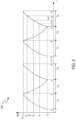
- FIG. 5 shows an example of voltage values versus time on a capacitor, in accordance with embodiments of the present invention
- FIG. 6 shows a flowchart of a method for detecting whether a battery management system is abnormal, in accordance with embodiments of the present invention
- FIG. 7 shows a flowchart of a method for detecting whether a battery management system is abnormal, in accordance with embodiments of the present invention
- FIG. 8 shows a flowchart of a method for detecting whether a battery management system is abnormal, in accordance with embodiments of the present invention
- FIG. 9 shows a flowchart of a method for detecting whether a battery management system is abnormal, in accordance with embodiments of the present invention.
- FIG. 10 shows a curve of an example of voltage values versus time on a capacitor, in accordance with embodiments of the present invention.
- FIG. 11 shows a flowchart of a method for detecting whether a battery management system is abnormal, in accordance with embodiments of the present invention.
- FIG. 12 shows a flowchart of a method for detecting whether a battery management system is abnormal, in accordance with embodiments of the present invention.
- FIG. 1 shows a block diagram illustrating a battery management system 100 , in accordance with embodiments of the present invention.
- the present invention includes methods for detecting whether the battery management system 100 is abnormal.
- a method includes: a preset range of a theoretical time constant is determined when the battery management system 100 is normal; a measured time constant is determined; and a determination is made as to whether the battery management system 100 is abnormal by comparing the measured time constant with the preset range of the theoretical time constant.
- the battery pack includes a cell CELL 1 , CELL 2 , . . . , CELLn, which are coupled in series.
- the battery management system 100 includes monitoring resistors RF 0 , RF 1 , . . . , RFn, capacitors CF 1 , CF 2 , . . . , CFn, balance resistors RB 1 , RB 2 , . . . , RBn, switches SW 1 , SW 2 , . . . , SWn, a measure unit 120 , and a control unit 110 .
- a monitoring resistor RF 0 is coupled to a negative electrode of a cell CELL 1 .
- the monitoring resistors RF 0 , RF 1 , RFn and capacitors CF 1 , CF 2 , . . . , CFn together form Resistor-Capacitance (RC) filters.
- the RC filters are operable for filtering out the high frequency components of voltages provided by the cells, thus eliminating unwanted noise components.
- the measure unit 120 is coupled to the monitoring resistors RF 0 , RF 1 , . . . , RFn, and is operable for measuring voltages of the cells in the battery pack. For example, the measure unit 120 determines a voltage V CELL2 of the cell CELL 2 by measuring the difference between a voltage at a node N 2 and a voltage at a node N 1 .
- V CELL2 e.g., 3V
- V CELL1 e.g., 3.4V
- both the balance resistor RBj and the switch SWj are operable for detecting whether the battery management system 100 is abnormal. A detailed description is given below.
- the control unit 110 includes a memory 111 and a microcontroller unit 112 .
- Program codes are written into the microcontroller unit 112 .
- the microcontroller unit 112 is configured to include or execute a timer 113 , to enable the microcontroller unit 112 to run the program code according to the time sequence set by the timer 113 , thereby realizing the control function and the data processing function.
- the memory 111 is operable for storing data, such as the theoretical time constant.
- control unit 110 controls the switches SW 1 , SW 2 , . . . , SWn to turn on/off, controls the measure unit 120 to measure a voltage on the capacitor CFj, and determines the measured time constant. Because the theoretical time constant and the preset range of the theoretical time constant are determined experimentally (e.g., before the battery management system 100 is put into use), they are stored in the memory 111 . If the measured time constant is in the preset range of the theoretical time constant, then the control unit 110 determines the battery management system 100 is normal; otherwise, the battery management system 100 is abnormal.
- Embodiments according to the present invention are not limited to the configuration of FIG. 1 .
- the methods described herein are applicable when the connection mode of the capacitor CFj in FIG. 1 is different, e.g., a terminal of the capacitor CFj is connected to the monitoring resistor RFj, and the other terminal is connected to ground of the battery management system 100 .
- FIG. 2 shows a circuit diagram illustrating a detection performed on a cell CELLj to determine whether a battery management system is abnormal, in accordance with embodiments of the present invention.
- FIG. 3 shows an example of the variation of the voltage values as a function of time (variation curve) on a capacitor CFj when a battery management system 100 is normal, in accordance with embodiments of the present invention, where the X-axis represents time and the Y-axis represents voltage values on the capacitor CFj.
- FIG. 3 is described in conjunction with FIG. 2 .
- the Battery Management System 100 is Normal.
- the control unit 110 controls the switch SWj to turn off, and the cell CELLj charges the capacitor CFj.
- the capacitor CFj is fully charged at time t 2 .
- the measure unit 120 measures the voltage value on the capacitor CFj (a difference between a voltage at a node N(j ⁇ 1) and a voltage at a node Nj) as the voltage V CELLj of the cell CELLj.
- the control unit 110 controls the switch SWj to turn on, and the capacitor CFj discharges.
- the capacitor CFj does not discharge any more at time t 3 .
- V E V CELLj ⁇ R RBj /(R RBj +R RFj +R RF(j ⁇ 1) ), where R RF(j ⁇ 1) represents a resistance value of the monitoring resistor RF(j ⁇ 1), R RFj represents a resistance value of the monitoring resistor RFj, and R RBj represents a resistance value of the monitoring resistor RBj.
- the control unit 110 controls the switch SWj to turn off, and the cell CELLj charges the capacitor CFj.
- the capacitor CFj is fully charged at time t 4 .
- the voltage value on the capacitor CFj is recovered from V E to V CELLj .
- time t 31 , time t 32 , . . . , time t 3n are selected in the time period from t 3 to t 4 , and the measure unit 120 respectively measures voltage values V 1 , V 2 , . . . , V n , on the capacitor CFj at time t 31 , time t 32 , . . . , time t 3n , to determine (V 1 , ⁇ t 1 ), (V 2 , ⁇ t 2 ), . . .
- ⁇ t 1 represents the length of time between time t 3 and time t 31
- ⁇ t 2 represents the length of time between time t 3 and time t 32
- ⁇ . . , and ⁇ t n represents the length of time between time t 3 and time t 3n .
- the monitoring resistors RFj, RF(j ⁇ 1) and the capacitor CFj form a RC circuit
- ⁇ t i represents the length of time between time t 3 and time t 3n .
- V 1 , ⁇ t 1 ), (V 2 , ⁇ t 2 ), . . . , (V n , ⁇ t n ) are substituted in the above equation to determine the coefficient K and the theoretical time constant ⁇ .
- K V CELLj ⁇ V E .
- each RC circuit is located in a different position in the battery management system 100 , so the theoretical time constant ⁇ corresponding to each RC circuit is not equal.
- Abnormities include an abnormal connection and an abnormal component. If the two terminals of the cell CELLj are not properly connected to the battery management system 100 (e.g., broken or degraded or not operating satisfactorily), then the connection between the battery management system 100 and the cell CELLj is referred to herein as an abnormal connection. If any of the capacitor CFj, the monitoring resistor RFj, and the monitoring resistor RF(j ⁇ 1) is inoperative (e.g., a leakage current of the capacitor CFj, the resistance values of the monitoring resistor RFj, and/or the monitoring resistor RF(j ⁇ 1) are increased/decreased), then this condition is referred to herein as an abnormal component.
- an abnormal component e.g., a leakage current of the capacitor CFj, the resistance values of the monitoring resistor RFj, and/or the monitoring resistor RF(j ⁇ 1) are increased/decreased
- the capacitor CFj cannot be charged in the time period from t 3 to t 4 and the voltage value on the capacitor CFj remains unchanged from time t 3 . Therefore, under ideal conditions, if the connection between the battery management system 100 and the cell CELLj is broken, then the voltage value on the capacitor CFj remains unchanged in the time period from t 3 to t 4 .
- the voltage value on the capacitor CFj is less than V E at time t 3 and cannot be recovered to V CELLj at time t 4 .
- the resistance value R RFj of the monitoring resistor RFj and/or the resistance value R RF(j ⁇ 1) of the monitoring resistor RF(j ⁇ 1) are increased, then the voltage value on the capacitor CFj can decrease to a voltage value near V E at time t 3 and cannot be recovered to V CELLj at time t 4 .
- the voltage value on the capacitor CFj can decrease to a voltage value near V E at time t 3 and can be recovered to V CELLj before time t 4 . Therefore, if one or more components among the capacitor CFj, the monitoring resistor RFj, and the monitoring resistor RF(j ⁇ 1) cannot work effectively, then the variation curve of the voltage values on the capacitor CFj in the time period from t 3 to t 4 will deviate from the curve of FIG. 3 when the battery management system 100 is normal.
- the variation curve of the voltage values on the capacitor CFj in the time period from t 3 to t 4 will deviate from the FIG. 3 curve when the battery management system 100 is normal. Because the variation curve of the voltage values on the capacitor CFj can be reflected by the time constant (that is, the variation curve of the voltage values on the capacitor CFj varies with the time constants), embodiments of the present invention compare the measured time constant with the preset range of the theoretical time constant to determine whether the battery management system 100 is abnormal.
- FIG. 4 shows a flowchart 400 of a method for detecting whether a battery management system 100 is abnormal, in accordance with embodiments of the present invention.
- FIG. 4 is described in conjunction with FIG. 2 and FIG. 5 .
- step 402 the control unit 110 controls the measure unit 120 to measure the voltage value on the capacitor CFj at time t 2 , to produce the voltage V CELLj of the cell CELLj.
- the control unit 110 controls the measure unit 120 to measure the voltage values on the capacitor CFj at least at one time point in the time period from t 3 to t 4 , to produce measured capacitance voltage value(s).
- the control unit 110 determines a theoretical time constant according to at least one measured capacitance voltage value and the measured voltage value V CELLj of the cell CELLj.
- the theoretical time constant is an experimentally determined value. Methods for determining the measured time constant are described in conjunction with the embodiments in FIG. 6 , FIG. 7 , FIG. 8 , FIG. 9 , and FIG. 11 .
- step 404 a preset range of the theoretical time constant is determined according to the theoretical time constant. Both the theoretical time constant and the preset range of the theoretical time constant are stored in the memory 111 of the control unit 110 .
- step 406 the control unit 110 controls the measure unit 120 to measure the voltage value on the capacitor CFj at time t 6 , to produce the voltage V CELLj of the cell CELLj.
- the control unit 110 controls the measure unit 120 to measure the voltage values on the capacitor CFj at least at one time point in the time period from t 7 to t 8 , to produce measured capacitance voltage values.
- the control unit 110 determines a measured time constant according to at least one measured capacitance voltage and the measured voltage value of the cell CELLj. Methods for determining the measured time constant are described in conjunction with the embodiments in FIG. 6 , FIG. 7 , FIG. 8 , FIG. 9 , and FIG. 11 .
- step 408 the control unit 110 determines whether the measured time constant is in the preset range of the theoretical time constant. If yes, then step 408 is followed by step 410 ; otherwise, step 408 is followed by step 409 .
- step 409 the control unit 110 determines that the battery management system 100 is abnormal, and generates an alarm to alert the users.
- step 410 the control unit 110 determines that the battery management system 100 is normal.
- step 411 the control unit 110 determines whether all of the cells are detected. If yes, then step 411 is followed by step 413 ; otherwise, step 411 is followed by step 412 .
- step 412 the battery management system 100 starts to detect the next cell, and the method returns to step 405 .
- step 413 the detection process of FIG. 4 is finished.
- FIG. 6 shows a flowchart 600 of a method for detecting whether a battery management system 100 is abnormal, in accordance with embodiments of the present invention.
- FIG. 6 is described in conjunction with FIG. 2 and FIG. 5 .
- step 602 the control unit 110 controls the measure unit 120 to measure the voltage value on the capacitor CFj at time t 6 , to produce the voltage V CELLj of the cell CELLj.
- step 603 the control unit 110 controls the measure unit 120 to measure the voltage value V 1 on the capacitor CFj at time t 71 in the time period from t 7 to t 8 , to determine (V 1 , ⁇ t 1 ), where ⁇ t 1 is the length of time between t 1 and t 71 .
- K V CELLj ⁇ V E .
- FIG. 7 shows a flowchart 700 of a method for detecting whether a battery management system 100 is abnormal, in accordance with embodiments of the present invention.
- FIG. 7 is described in conjunction with FIG. 2 and FIG. 5 . If the length of time of the third time period T 3 is long enough for the control unit 110 to complete the calculation, the method of FIG. 7 can be used to determine the measured time constant. Compared with the embodiment of FIG. 6 , the embodiment of FIG. 7 can further improve the accuracy of the measured time constant, thereby improving the detection accuracy.
- step 702 the control unit 110 controls the measure unit 120 to measure the voltage values on the capacitor CFj at time t 6 , to produce the voltage V CELLj of the cell CELLj.
- step 703 the control unit 110 controls the measure unit 120 to measure the voltage value V 1 on the capacitor CFj at time t 71 in the time period from t 7 to t 8 , to determine (V 1 , ⁇ t 1 ), where ⁇ t 1 is the length of time between t 7 and t 71 .
- step 704 the control unit 110 controls the measure unit 120 to measure the voltage value V 2 on the capacitor CFj at time t 72 in the time period from t 7 to t 8 , to determine (V 2 , ⁇ t 2 ), where ⁇ t 2 is the length of time between t 7 and t 72 , and ⁇ t 2 is not equal to ⁇ t 1 .
- FIG. 8 shows a flowchart 800 of a method for detecting whether a battery management system 100 is abnormal, in accordance with embodiments of the present invention.
- FIG. 8 is described in conjunction with FIG. 2 and FIG. 5 . If the length of time of the third time period T 3 is long enough for the control unit 110 to complete the calculation, the method of FIG. 8 can be used to determine the measured time constant. Compared with the embodiment of FIG. 7 , the embodiment of FIG. 8 can further improve the accuracy of the measured time constant, thereby improving the detection accuracy.
- step 802 the control unit 110 controls the measure unit 120 to measure the voltage value on the capacitor CFj at time t 6 , to produce the voltage V CELLj of the cell CELLj.
- step 803 the control unit 110 controls the measure unit 120 to measure the voltage value V 1 on the capacitor CFj at time t 71 in the time period from t 7 to t 8 , to determine (V 1 , ⁇ t 1 ), where ⁇ t 1 is the length of time between t 7 and t 71 .
- step 804 the control unit 110 controls the measure unit 120 to measure the voltage value V 2 on the capacitor CFj at time t 72 in the time period from t 7 to t 8 , to determine (V 2 , ⁇ t 2 ), where ⁇ t n is the length of time between t 7 and t 72 , and ⁇ t 2 is not equal to ⁇ t 1 .
- step 805 this process continues until the control unit 110 controls the measure unit 120 to measure the voltage value V n on the capacitor CFj at time t 7n in the time period from t 7 to t 8 , to determine (V n , ⁇ t n ), where ⁇ t n is the length of time between t 7 and t 7n .
- ⁇ t 1 , ⁇ t 2 , . . . , ⁇ t n are not equal to each other.
- ⁇ t n ⁇ (t n ⁇ 1 ), . . . , ⁇ t 3 ⁇ t 2 , ⁇ t 2 ⁇ t 1 .
- two adjacent time periods are not equal.
- step 809 the control unit 110 averages ⁇ 1 , ⁇ 2 , . . . , ⁇ (n ⁇ 1) to determine the measured time constant.
- other methods can be used to calculate ⁇ 1 , ⁇ 2 , . . . , ⁇ (n ⁇ 1) to determine the measured time constant.
- FIG. 9 shows a flowchart 900 of a method for detecting whether a battery management system 100 is abnormal, in accordance with embodiments of the present invention.
- FIG. 9 is described in conjunction with FIG. 2 and FIG. 10 .
- the embodiment of FIG. 9 can reduce uncertainty in the measured time constant that may be introduced by uncertainty in the coefficient K, thereby improving the detection accuracy.
- step 902 the control unit 110 controls the measure unit 120 to measure the voltage value on the capacitor CFj at time t 6 , to produce the voltage V CELLj of the cell CELLj.
- step 903 the control unit 110 controls the measure unit 120 to measure the voltage value V 1 on the capacitor CFj at time t 71 in the time period from t 7 to t 8 , to determine (V 1 , ⁇ t 1 ), where ⁇ t 1 is the length of time between t 7 and t 71 .
- step 904 the control unit 110 controls the measure unit 120 to measure the voltage value V 2 on the capacitor CFj at time t 72 in the time period from t 9 to t 10 , to determine (V 2 , ⁇ t 2 ), where ⁇ t 2 is the length of time between t 9 and t 72 , and ⁇ t 2 is not equal to ⁇ t 1 .
- FIG. 11 shows a flowchart 1100 of a method for detecting whether a battery management system 100 is abnormal, in accordance with embodiments of the present invention.
- FIG. 11 is described in conjunction with FIG. 2 and FIG. 10 .
- the embodiment of FIG. 11 can further improve the accuracy of the measured time constant, thereby improving detection accuracy.
- step 1102 the control unit 110 controls the measure unit 120 to measure the voltage value V 1 on the capacitor CFj at time t 71 in the time period from t 7 to t 8 , to determine (V 1 , ⁇ t 1 ), where ⁇ t 1 is the length of time between t 7 and t 71 .
- step 1103 the control unit 110 controls the measure unit 120 to measure the voltage value V 2 on the capacitor CFj at time t 72 in the time period from t 9 to t 10 , to determine (V 2 , ⁇ t 2 ), where ⁇ t 2 is the length of time between t 9 and t 72 , and ⁇ t 2 is not equal to ⁇ t 1 .
- step 1104 this process continues until the control unit 110 controls the measure unit 120 to measure the voltage value V n on the capacitor CFj at time t 7n in the time period from t (5+2n) to t (6+2n) , to determine (V n , ⁇ t n ), where ⁇ t n is the length of time between t (5+2n) and t 7n .
- ⁇ t 1 , ⁇ t 2 , . . . , ⁇ t n are not equal to each other.
- two or more of ⁇ t 1 , ⁇ t 2 , . . . , ⁇ t n can be equal.
- step 1105 based on (V 1 , ⁇ t 1 ), (V 2 , ⁇ t 2 ), . . . , (V n , ⁇ t n ), the control unit 110 uses the least square method to fit the variation curve of the voltage value on the capacitor CFj, to determine the measured time constant.
- other methods can be used to fit the variation curve of the voltage value on the capacitor CFj based on (V 1 , ⁇ t 1 ), (V 2 , ⁇ t 2 ), . . . , (V n , ⁇ t n ), to determine the measured time constant.
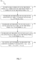
- FIG. 12 shows a flowchart 1200 of a method for detecting whether a battery management system 100 is abnormal.
- FIG. 12 is described in conjunction with FIG. 1 .
- the method includes a first stage 1210 and a second stage 1220 .
- the first stage 1210 includes steps 1201 and 1202 .
- step 1201 the control unit 110 determines a theoretical time constant corresponding to the first cell CELL 1 , when the battery management system 100 is normal.
- step 1202 a preset range of the theoretical time constant is determined according to the theoretical time constant.
- the second stage 1220 includes steps 1203 through 1207 .
- step 1203 the control unit 110 controls the first switch SW 1 to successively turn off for a first time period T 1 , turn on for a second time period T 2 , and turn off for a third time period T 3 .
- step 1204 the control unit 110 controls the measure unit 120 to measure a voltage value on the first capacitor CF 1 at the end of the first time period T 1 , to produce a measured voltage value of the first cell CELL 1 .
- step 1205 the control unit 110 controls the measure unit 120 to measure voltage values on the first capacitor CF 1 at least at one time point in the third time period T 3 , to produce measured capacitance voltage values.
- step 1206 the control unit 110 determines a value of a measured time constant according to at least one measured capacitance voltage value and the measured voltage value of the first cell CELL 1 .
- step 1207 the control unit 110 determines that the battery management system 100 is abnormal, if the value of the measured time constant exceeds the preset range of the theoretical time constant.
- embodiments according to the present invention pertain to methods for detecting whether a battery management system is abnormal.
- the method can accurately detect whether the battery management system is abnormal (e.g., the connection between the battery management system and a cell CELLj is degraded or broken, the R RFj and/or the R RF(j ⁇ 1) are increased/decreased, or a leakage current of the capacitor CFj), thereby improving the detection accuracy.
Landscapes
- Engineering & Computer Science (AREA)
- Physics & Mathematics (AREA)
- General Physics & Mathematics (AREA)
- Power Engineering (AREA)
- Chemical Kinetics & Catalysis (AREA)
- Chemical & Material Sciences (AREA)
- Manufacturing & Machinery (AREA)
- Electrochemistry (AREA)
- General Chemical & Material Sciences (AREA)
- Microelectronics & Electronic Packaging (AREA)
- Measurement Of Current Or Voltage (AREA)
- Charge And Discharge Circuits For Batteries Or The Like (AREA)
- Secondary Cells (AREA)
Abstract
Description
Claims (20)
Priority Applications (2)
| Application Number | Priority Date | Filing Date | Title |
|---|---|---|---|
| US17/204,759 US12061237B2 (en) | 2018-04-20 | 2021-03-17 | Detecting whether a battery management system is abnormal |
| EP21168550.8A EP4040566B1 (en) | 2021-02-09 | 2021-04-15 | Detecting whether a battery management system is abnormal |
Applications Claiming Priority (4)
| Application Number | Priority Date | Filing Date | Title |
|---|---|---|---|
| US15/959,064 US11038356B2 (en) | 2017-04-24 | 2018-04-20 | Open cell detection method and open cell recovery detection method in a battery management system |
| CN202110175863.2 | 2021-02-09 | ||
| CN202110175863.2A CN114910790B (en) | 2021-02-09 | 2021-02-09 | Abnormality detection method in battery management system and battery management system |
| US17/204,759 US12061237B2 (en) | 2018-04-20 | 2021-03-17 | Detecting whether a battery management system is abnormal |
Related Parent Applications (1)
| Application Number | Title | Priority Date | Filing Date |
|---|---|---|---|
| US15/959,064 Continuation-In-Part US11038356B2 (en) | 2017-04-24 | 2018-04-20 | Open cell detection method and open cell recovery detection method in a battery management system |
Publications (2)
| Publication Number | Publication Date |
|---|---|
| US20210199722A1 US20210199722A1 (en) | 2021-07-01 |
| US12061237B2 true US12061237B2 (en) | 2024-08-13 |
Family
ID=75539152
Family Applications (1)
| Application Number | Title | Priority Date | Filing Date |
|---|---|---|---|
| US17/204,759 Active 2040-04-08 US12061237B2 (en) | 2018-04-20 | 2021-03-17 | Detecting whether a battery management system is abnormal |
Country Status (2)
| Country | Link |
|---|---|
| US (1) | US12061237B2 (en) |
| EP (1) | EP4040566B1 (en) |
Families Citing this family (2)
| Publication number | Priority date | Publication date | Assignee | Title |
|---|---|---|---|---|
| US20240175924A1 (en) * | 2022-11-30 | 2024-05-30 | O2Micro Inc. | Battery monitoring circuits |
| KR20260018604A (en) * | 2024-07-31 | 2026-02-09 | 삼성에스디아이 주식회사 | Apparatus and method for battery cell ballancing, battery management system |
Citations (3)
| Publication number | Priority date | Publication date | Assignee | Title |
|---|---|---|---|---|
| JP2015175676A (en) | 2014-03-14 | 2015-10-05 | 日立オートモティブシステムズ株式会社 | Electronic control device |
| US20180043781A1 (en) | 2015-03-11 | 2018-02-15 | Hitachi Automotive Systems, Ltd. | Battery managing device, battery monitoring circuit, and control system |
| US20180316197A1 (en) | 2017-04-24 | 2018-11-01 | O2Micro, Inc. | Open cell detection method and open cell recovery detection method in a battery management system |
-
2021
- 2021-03-17 US US17/204,759 patent/US12061237B2/en active Active
- 2021-04-15 EP EP21168550.8A patent/EP4040566B1/en active Active
Patent Citations (5)
| Publication number | Priority date | Publication date | Assignee | Title |
|---|---|---|---|---|
| JP2015175676A (en) | 2014-03-14 | 2015-10-05 | 日立オートモティブシステムズ株式会社 | Electronic control device |
| US20180043781A1 (en) | 2015-03-11 | 2018-02-15 | Hitachi Automotive Systems, Ltd. | Battery managing device, battery monitoring circuit, and control system |
| US10449862B2 (en) * | 2015-03-11 | 2019-10-22 | Hitachi Automotive Systems, Ltd. | Battery managing device, battery monitoring circuit, and control system |
| US20180316197A1 (en) | 2017-04-24 | 2018-11-01 | O2Micro, Inc. | Open cell detection method and open cell recovery detection method in a battery management system |
| US11038356B2 (en) * | 2017-04-24 | 2021-06-15 | O2Micro Inc. | Open cell detection method and open cell recovery detection method in a battery management system |
Also Published As
| Publication number | Publication date |
|---|---|
| EP4040566A1 (en) | 2022-08-10 |
| EP4040566B1 (en) | 2024-08-07 |
| US20210199722A1 (en) | 2021-07-01 |
Similar Documents
| Publication | Publication Date | Title |
|---|---|---|
| US11927642B2 (en) | Open cell detection method and open cell recovery detection method in a battery management system | |
| US9018959B2 (en) | Insulating state detection unit having failure detector | |
| US11777154B2 (en) | Battery management systems and methods, and open cell detection systems | |
| CN108808759B (en) | Battery device and battery protection method | |
| CN106461732A (en) | Method for estimating state of health of battery | |
| US12061237B2 (en) | Detecting whether a battery management system is abnormal | |
| CN114514433A (en) | Apparatus and method for diagnosing battery | |
| JP2006207269A (en) | Capacitance detection device | |
| JP2018147680A (en) | Temperature abnormality determination device, temperature abnormality determination method, and computer program | |
| CN108966670A (en) | Voltameter and its current acquisition calibration circuit and calibration method | |
| EP1037065B1 (en) | Battery charge monitor for an electronic appliance | |
| CN111521945A (en) | Battery health state detection method, device, electronic device and storage medium | |
| JP4048970B2 (en) | Flying capacitor voltage detection circuit | |
| US8552753B2 (en) | Circuits and methods for sensing resistance | |
| CN114910790B (en) | Abnormality detection method in battery management system and battery management system | |
| JP7705756B2 (en) | BATTERY STATE ESTIMATION METHOD AND BATTERY STATE ESTIMATION DEVICE | |
| CN113281676A (en) | Method and device for judging leakage current inside battery and battery management system | |
| CN109991462A (en) | Voltage detecting circuit, method and system | |
| CN116893355A (en) | Methods, integrated circuits and devices for monitoring batteries | |
| KR101175369B1 (en) | Apparatus and Methode of measuring charges in a battery | |
| JP3175654B2 (en) | Capacitor measurement terminal contact detection method | |
| US20200057524A1 (en) | Touch sensing device and touch sensing method | |
| CA2981224A1 (en) | Method for validating fuse heads | |
| KR20030053925A (en) | Method for Detecting and Correcting Error on Remaining Capacity Data of Battery for Mobile Communication Device | |
| JP2024136183A (en) | Battery deterioration determination device, storage battery system, and battery deterioration determination method |
Legal Events
| Date | Code | Title | Description |
|---|---|---|---|
| AS | Assignment |
Owner name: O2MICRO INC., CALIFORNIA Free format text: ASSIGNMENT OF ASSIGNORS INTEREST;ASSIGNORS:LI, GUOXING;ZENG, XIAOJUN;ZHANG, YINGGUO;SIGNING DATES FROM 20210302 TO 20210303;REEL/FRAME:055629/0623 |
|
| FEPP | Fee payment procedure |
Free format text: ENTITY STATUS SET TO UNDISCOUNTED (ORIGINAL EVENT CODE: BIG.); ENTITY STATUS OF PATENT OWNER: SMALL ENTITY |
|
| FEPP | Fee payment procedure |
Free format text: ENTITY STATUS SET TO SMALL (ORIGINAL EVENT CODE: SMAL); ENTITY STATUS OF PATENT OWNER: SMALL ENTITY |
|
| STPP | Information on status: patent application and granting procedure in general |
Free format text: APPLICATION DISPATCHED FROM PREEXAM, NOT YET DOCKETED |
|
| STPP | Information on status: patent application and granting procedure in general |
Free format text: DOCKETED NEW CASE - READY FOR EXAMINATION |
|
| AS | Assignment |
Owner name: CREDIT SUISSE AG, SINGAPORE BRANCH, AS SECURITY AGENT, SINGAPORE Free format text: IP SECURITY AGREEMENT SUPPLEMENT;ASSIGNOR:O2 MICRO, INC.;REEL/FRAME:064259/0696 Effective date: 20230705 |
|
| STPP | Information on status: patent application and granting procedure in general |
Free format text: EX PARTE QUAYLE ACTION MAILED |
|
| STPP | Information on status: patent application and granting procedure in general |
Free format text: RESPONSE TO EX PARTE QUAYLE ACTION ENTERED AND FORWARDED TO EXAMINER |
|
| STPP | Information on status: patent application and granting procedure in general |
Free format text: NOTICE OF ALLOWANCE MAILED -- APPLICATION RECEIVED IN OFFICE OF PUBLICATIONS |
|
| ZAAA | Notice of allowance and fees due |
Free format text: ORIGINAL CODE: NOA |
|
| ZAAB | Notice of allowance mailed |
Free format text: ORIGINAL CODE: MN/=. |
|
| STPP | Information on status: patent application and granting procedure in general |
Free format text: PUBLICATIONS -- ISSUE FEE PAYMENT VERIFIED |
|
| STCF | Information on status: patent grant |
Free format text: PATENTED CASE |
|
| AS | Assignment |
Owner name: UBS AG, SINGAPORE BRANCH, AS SECURITY AGENT, SINGAPORE Free format text: CHANGE OF NAME;ASSIGNOR:CREDIT SUISSE AG, SINGAPORE BRANCH. AS SECURITY AGENT;REEL/FRAME:069242/0457 Effective date: 20230705 |