US12059995B2 - Apparatus and method for correcting level of headlamp - Google Patents
Apparatus and method for correcting level of headlamp Download PDFInfo
- Publication number
- US12059995B2 US12059995B2 US17/479,512 US202117479512A US12059995B2 US 12059995 B2 US12059995 B2 US 12059995B2 US 202117479512 A US202117479512 A US 202117479512A US 12059995 B2 US12059995 B2 US 12059995B2
- Authority
- US
- United States
- Prior art keywords
- headlamp
- level
- number plate
- plate frame
- vehicle
- Prior art date
- Legal status (The legal status is an assumption and is not a legal conclusion. Google has not performed a legal analysis and makes no representation as to the accuracy of the status listed.)
- Active, expires
Links
Images


Classifications
-
- B—PERFORMING OPERATIONS; TRANSPORTING
- B60—VEHICLES IN GENERAL
- B60Q—ARRANGEMENT OF SIGNALLING OR LIGHTING DEVICES, THE MOUNTING OR SUPPORTING THEREOF OR CIRCUITS THEREFOR, FOR VEHICLES IN GENERAL
- B60Q1/00—Arrangement of optical signalling or lighting devices, the mounting or supporting thereof or circuits therefor
- B60Q1/02—Arrangement of optical signalling or lighting devices, the mounting or supporting thereof or circuits therefor the devices being primarily intended to illuminate the way ahead or to illuminate other areas of way or environments
- B60Q1/04—Arrangement of optical signalling or lighting devices, the mounting or supporting thereof or circuits therefor the devices being primarily intended to illuminate the way ahead or to illuminate other areas of way or environments the devices being headlights
- B60Q1/06—Arrangement of optical signalling or lighting devices, the mounting or supporting thereof or circuits therefor the devices being primarily intended to illuminate the way ahead or to illuminate other areas of way or environments the devices being headlights adjustable, e.g. remotely-controlled from inside vehicle
- B60Q1/08—Arrangement of optical signalling or lighting devices, the mounting or supporting thereof or circuits therefor the devices being primarily intended to illuminate the way ahead or to illuminate other areas of way or environments the devices being headlights adjustable, e.g. remotely-controlled from inside vehicle automatically
- B60Q1/085—Arrangement of optical signalling or lighting devices, the mounting or supporting thereof or circuits therefor the devices being primarily intended to illuminate the way ahead or to illuminate other areas of way or environments the devices being headlights adjustable, e.g. remotely-controlled from inside vehicle automatically due to special conditions, e.g. adverse weather, type of road, badly illuminated road signs or potential dangers
-
- B—PERFORMING OPERATIONS; TRANSPORTING
- B60—VEHICLES IN GENERAL
- B60Q—ARRANGEMENT OF SIGNALLING OR LIGHTING DEVICES, THE MOUNTING OR SUPPORTING THEREOF OR CIRCUITS THEREFOR, FOR VEHICLES IN GENERAL
- B60Q1/00—Arrangement of optical signalling or lighting devices, the mounting or supporting thereof or circuits therefor
- B60Q1/02—Arrangement of optical signalling or lighting devices, the mounting or supporting thereof or circuits therefor the devices being primarily intended to illuminate the way ahead or to illuminate other areas of way or environments
- B60Q1/04—Arrangement of optical signalling or lighting devices, the mounting or supporting thereof or circuits therefor the devices being primarily intended to illuminate the way ahead or to illuminate other areas of way or environments the devices being headlights
- B60Q1/06—Arrangement of optical signalling or lighting devices, the mounting or supporting thereof or circuits therefor the devices being primarily intended to illuminate the way ahead or to illuminate other areas of way or environments the devices being headlights adjustable, e.g. remotely-controlled from inside vehicle
- B60Q1/08—Arrangement of optical signalling or lighting devices, the mounting or supporting thereof or circuits therefor the devices being primarily intended to illuminate the way ahead or to illuminate other areas of way or environments the devices being headlights adjustable, e.g. remotely-controlled from inside vehicle automatically
- B60Q1/10—Arrangement of optical signalling or lighting devices, the mounting or supporting thereof or circuits therefor the devices being primarily intended to illuminate the way ahead or to illuminate other areas of way or environments the devices being headlights adjustable, e.g. remotely-controlled from inside vehicle automatically due to vehicle inclination, e.g. due to load distribution
-
- B—PERFORMING OPERATIONS; TRANSPORTING
- B60—VEHICLES IN GENERAL
- B60Q—ARRANGEMENT OF SIGNALLING OR LIGHTING DEVICES, THE MOUNTING OR SUPPORTING THEREOF OR CIRCUITS THEREFOR, FOR VEHICLES IN GENERAL
- B60Q1/00—Arrangement of optical signalling or lighting devices, the mounting or supporting thereof or circuits therefor
- B60Q1/02—Arrangement of optical signalling or lighting devices, the mounting or supporting thereof or circuits therefor the devices being primarily intended to illuminate the way ahead or to illuminate other areas of way or environments
- B60Q1/04—Arrangement of optical signalling or lighting devices, the mounting or supporting thereof or circuits therefor the devices being primarily intended to illuminate the way ahead or to illuminate other areas of way or environments the devices being headlights
- B60Q1/06—Arrangement of optical signalling or lighting devices, the mounting or supporting thereof or circuits therefor the devices being primarily intended to illuminate the way ahead or to illuminate other areas of way or environments the devices being headlights adjustable, e.g. remotely-controlled from inside vehicle
- B60Q1/08—Arrangement of optical signalling or lighting devices, the mounting or supporting thereof or circuits therefor the devices being primarily intended to illuminate the way ahead or to illuminate other areas of way or environments the devices being headlights adjustable, e.g. remotely-controlled from inside vehicle automatically
-
- B—PERFORMING OPERATIONS; TRANSPORTING
- B60—VEHICLES IN GENERAL
- B60K—ARRANGEMENT OR MOUNTING OF PROPULSION UNITS OR OF TRANSMISSIONS IN VEHICLES; ARRANGEMENT OR MOUNTING OF PLURAL DIVERSE PRIME-MOVERS IN VEHICLES; AUXILIARY DRIVES FOR VEHICLES; INSTRUMENTATION OR DASHBOARDS FOR VEHICLES; ARRANGEMENTS IN CONNECTION WITH COOLING, AIR INTAKE, GAS EXHAUST OR FUEL SUPPLY OF PROPULSION UNITS IN VEHICLES
- B60K35/00—Instruments specially adapted for vehicles; Arrangement of instruments in or on vehicles
- B60K35/20—Output arrangements, i.e. from vehicle to user, associated with vehicle functions or specially adapted therefor
- B60K35/21—Output arrangements, i.e. from vehicle to user, associated with vehicle functions or specially adapted therefor using visual output, e.g. blinking lights or matrix displays
- B60K35/22—Display screens
-
- B—PERFORMING OPERATIONS; TRANSPORTING
- B60—VEHICLES IN GENERAL
- B60K—ARRANGEMENT OR MOUNTING OF PROPULSION UNITS OR OF TRANSMISSIONS IN VEHICLES; ARRANGEMENT OR MOUNTING OF PLURAL DIVERSE PRIME-MOVERS IN VEHICLES; AUXILIARY DRIVES FOR VEHICLES; INSTRUMENTATION OR DASHBOARDS FOR VEHICLES; ARRANGEMENTS IN CONNECTION WITH COOLING, AIR INTAKE, GAS EXHAUST OR FUEL SUPPLY OF PROPULSION UNITS IN VEHICLES
- B60K35/00—Instruments specially adapted for vehicles; Arrangement of instruments in or on vehicles
- B60K35/20—Output arrangements, i.e. from vehicle to user, associated with vehicle functions or specially adapted therefor
- B60K35/21—Output arrangements, i.e. from vehicle to user, associated with vehicle functions or specially adapted therefor using visual output, e.g. blinking lights or matrix displays
- B60K35/23—Head-up displays [HUD]
- B60K35/231—Head-up displays [HUD] characterised by their arrangement or structure for integration into vehicles
-
- B—PERFORMING OPERATIONS; TRANSPORTING
- B60—VEHICLES IN GENERAL
- B60Q—ARRANGEMENT OF SIGNALLING OR LIGHTING DEVICES, THE MOUNTING OR SUPPORTING THEREOF OR CIRCUITS THEREFOR, FOR VEHICLES IN GENERAL
- B60Q1/00—Arrangement of optical signalling or lighting devices, the mounting or supporting thereof or circuits therefor
- B60Q1/0017—Devices integrating an element dedicated to another function
- B60Q1/0023—Devices integrating an element dedicated to another function the element being a sensor, e.g. distance sensor, camera
-
- B—PERFORMING OPERATIONS; TRANSPORTING
- B60—VEHICLES IN GENERAL
- B60Q—ARRANGEMENT OF SIGNALLING OR LIGHTING DEVICES, THE MOUNTING OR SUPPORTING THEREOF OR CIRCUITS THEREFOR, FOR VEHICLES IN GENERAL
- B60Q1/00—Arrangement of optical signalling or lighting devices, the mounting or supporting thereof or circuits therefor
- B60Q1/02—Arrangement of optical signalling or lighting devices, the mounting or supporting thereof or circuits therefor the devices being primarily intended to illuminate the way ahead or to illuminate other areas of way or environments
- B60Q1/04—Arrangement of optical signalling or lighting devices, the mounting or supporting thereof or circuits therefor the devices being primarily intended to illuminate the way ahead or to illuminate other areas of way or environments the devices being headlights
- B60Q1/0408—Arrangement of optical signalling or lighting devices, the mounting or supporting thereof or circuits therefor the devices being primarily intended to illuminate the way ahead or to illuminate other areas of way or environments the devices being headlights built into the vehicle body, e.g. details concerning the mounting of the headlamps on the vehicle body
- B60Q1/045—Arrangement of optical signalling or lighting devices, the mounting or supporting thereof or circuits therefor the devices being primarily intended to illuminate the way ahead or to illuminate other areas of way or environments the devices being headlights built into the vehicle body, e.g. details concerning the mounting of the headlamps on the vehicle body with provision for adjusting the alignment of the headlamp housing with respect to the vehicle body
-
- B—PERFORMING OPERATIONS; TRANSPORTING
- B60—VEHICLES IN GENERAL
- B60Q—ARRANGEMENT OF SIGNALLING OR LIGHTING DEVICES, THE MOUNTING OR SUPPORTING THEREOF OR CIRCUITS THEREFOR, FOR VEHICLES IN GENERAL
- B60Q9/00—Arrangement or adaptation of signal devices not provided for in one of main groups B60Q1/00 - B60Q7/00, e.g. haptic signalling
-
- G—PHYSICS
- G01—MEASURING; TESTING
- G01S—RADIO DIRECTION-FINDING; RADIO NAVIGATION; DETERMINING DISTANCE OR VELOCITY BY USE OF RADIO WAVES; LOCATING OR PRESENCE-DETECTING BY USE OF THE REFLECTION OR RERADIATION OF RADIO WAVES; ANALOGOUS ARRANGEMENTS USING OTHER WAVES
- G01S13/00—Systems using the reflection or reradiation of radio waves, e.g. radar systems; Analogous systems using reflection or reradiation of waves whose nature or wavelength is irrelevant or unspecified
- G01S13/02—Systems using reflection of radio waves, e.g. primary radar systems; Analogous systems
- G01S13/06—Systems determining position data of a target
- G01S13/08—Systems for measuring distance only
-
- G—PHYSICS
- G01—MEASURING; TESTING
- G01S—RADIO DIRECTION-FINDING; RADIO NAVIGATION; DETERMINING DISTANCE OR VELOCITY BY USE OF RADIO WAVES; LOCATING OR PRESENCE-DETECTING BY USE OF THE REFLECTION OR RERADIATION OF RADIO WAVES; ANALOGOUS ARRANGEMENTS USING OTHER WAVES
- G01S13/00—Systems using the reflection or reradiation of radio waves, e.g. radar systems; Analogous systems using reflection or reradiation of waves whose nature or wavelength is irrelevant or unspecified
- G01S13/88—Radar or analogous systems specially adapted for specific applications
- G01S13/93—Radar or analogous systems specially adapted for specific applications for anti-collision purposes
- G01S13/931—Radar or analogous systems specially adapted for specific applications for anti-collision purposes of land vehicles
-
- G—PHYSICS
- G02—OPTICS
- G02B—OPTICAL ELEMENTS, SYSTEMS OR APPARATUS
- G02B27/00—Optical systems or apparatus not provided for by any of the groups G02B1/00 - G02B26/00, G02B30/00
- G02B27/01—Head-up displays
-
- G—PHYSICS
- G06—COMPUTING OR CALCULATING; COUNTING
- G06V—IMAGE OR VIDEO RECOGNITION OR UNDERSTANDING
- G06V20/00—Scenes; Scene-specific elements
- G06V20/50—Context or environment of the image
- G06V20/56—Context or environment of the image exterior to a vehicle by using sensors mounted on the vehicle
- G06V20/58—Recognition of moving objects or obstacles, e.g. vehicles or pedestrians; Recognition of traffic objects, e.g. traffic signs, traffic lights or roads
- G06V20/584—Recognition of moving objects or obstacles, e.g. vehicles or pedestrians; Recognition of traffic objects, e.g. traffic signs, traffic lights or roads of vehicle lights or traffic lights
-
- B—PERFORMING OPERATIONS; TRANSPORTING
- B60—VEHICLES IN GENERAL
- B60K—ARRANGEMENT OR MOUNTING OF PROPULSION UNITS OR OF TRANSMISSIONS IN VEHICLES; ARRANGEMENT OR MOUNTING OF PLURAL DIVERSE PRIME-MOVERS IN VEHICLES; AUXILIARY DRIVES FOR VEHICLES; INSTRUMENTATION OR DASHBOARDS FOR VEHICLES; ARRANGEMENTS IN CONNECTION WITH COOLING, AIR INTAKE, GAS EXHAUST OR FUEL SUPPLY OF PROPULSION UNITS IN VEHICLES
- B60K2360/00—Indexing scheme associated with groups B60K35/00 or B60K37/00 relating to details of instruments or dashboards
- B60K2360/16—Type of output information
- B60K2360/171—Vehicle or relevant part thereof displayed
-
- B—PERFORMING OPERATIONS; TRANSPORTING
- B60—VEHICLES IN GENERAL
- B60K—ARRANGEMENT OR MOUNTING OF PROPULSION UNITS OR OF TRANSMISSIONS IN VEHICLES; ARRANGEMENT OR MOUNTING OF PLURAL DIVERSE PRIME-MOVERS IN VEHICLES; AUXILIARY DRIVES FOR VEHICLES; INSTRUMENTATION OR DASHBOARDS FOR VEHICLES; ARRANGEMENTS IN CONNECTION WITH COOLING, AIR INTAKE, GAS EXHAUST OR FUEL SUPPLY OF PROPULSION UNITS IN VEHICLES
- B60K35/00—Instruments specially adapted for vehicles; Arrangement of instruments in or on vehicles
- B60K35/20—Output arrangements, i.e. from vehicle to user, associated with vehicle functions or specially adapted therefor
- B60K35/28—Output arrangements, i.e. from vehicle to user, associated with vehicle functions or specially adapted therefor characterised by the type of the output information, e.g. video entertainment or vehicle dynamics information; characterised by the purpose of the output information, e.g. for attracting the attention of the driver
-
- B—PERFORMING OPERATIONS; TRANSPORTING
- B60—VEHICLES IN GENERAL
- B60Q—ARRANGEMENT OF SIGNALLING OR LIGHTING DEVICES, THE MOUNTING OR SUPPORTING THEREOF OR CIRCUITS THEREFOR, FOR VEHICLES IN GENERAL
- B60Q2300/00—Indexing codes for automatically adjustable headlamps or automatically dimmable headlamps
- B60Q2300/40—Indexing codes relating to other road users or special conditions
- B60Q2300/41—Indexing codes relating to other road users or special conditions preceding vehicle
-
- G—PHYSICS
- G01—MEASURING; TESTING
- G01S—RADIO DIRECTION-FINDING; RADIO NAVIGATION; DETERMINING DISTANCE OR VELOCITY BY USE OF RADIO WAVES; LOCATING OR PRESENCE-DETECTING BY USE OF THE REFLECTION OR RERADIATION OF RADIO WAVES; ANALOGOUS ARRANGEMENTS USING OTHER WAVES
- G01S7/00—Details of systems according to groups G01S13/00, G01S15/00, G01S17/00
- G01S7/02—Details of systems according to groups G01S13/00, G01S15/00, G01S17/00 of systems according to group G01S13/00
- G01S7/41—Details of systems according to groups G01S13/00, G01S15/00, G01S17/00 of systems according to group G01S13/00 using analysis of echo signal for target characterisation; Target signature; Target cross-section
-
- G—PHYSICS
- G02—OPTICS
- G02B—OPTICAL ELEMENTS, SYSTEMS OR APPARATUS
- G02B27/00—Optical systems or apparatus not provided for by any of the groups G02B1/00 - G02B26/00, G02B30/00
- G02B27/01—Head-up displays
- G02B27/0101—Head-up displays characterised by optical features
- G02B2027/0141—Head-up displays characterised by optical features characterised by the informative content of the display
-
- G—PHYSICS
- G06—COMPUTING OR CALCULATING; COUNTING
- G06T—IMAGE DATA PROCESSING OR GENERATION, IN GENERAL
- G06T7/00—Image analysis
- G06T7/10—Segmentation; Edge detection
- G06T7/11—Region-based segmentation
-
- G—PHYSICS
- G06—COMPUTING OR CALCULATING; COUNTING
- G06V—IMAGE OR VIDEO RECOGNITION OR UNDERSTANDING
- G06V20/00—Scenes; Scene-specific elements
- G06V20/50—Context or environment of the image
- G06V20/56—Context or environment of the image exterior to a vehicle by using sensors mounted on the vehicle
- G06V20/58—Recognition of moving objects or obstacles, e.g. vehicles or pedestrians; Recognition of traffic objects, e.g. traffic signs, traffic lights or roads
-
- G—PHYSICS
- G06—COMPUTING OR CALCULATING; COUNTING
- G06V—IMAGE OR VIDEO RECOGNITION OR UNDERSTANDING
- G06V20/00—Scenes; Scene-specific elements
- G06V20/60—Type of objects
- G06V20/62—Text, e.g. of license plates, overlay texts or captions on TV images
- G06V20/625—License plates
Definitions
- the present disclosure relates to an apparatus and a method for correcting a level of a headlamp, which may automatically correct a lighting angle of the headlamp to a preset ideal target line or induce a diver to perform a correction operation.
- Headlamp leveling devices applied to vehicles recently include a switch type that requests a driver to perform an operation for adjusting a level of a headlamp and an automatic correction type that automatically adjusts a level of a headlamp. Then, according to the switch type, a driver corrects a height of a headlamp while moving a switch provided in a vehicle upwards and downwards, but it is not rarely used and it is not difficult to find a proper height.
- the manual HLLD system may correct the height of the headlamp according to determination of the driver, but because an additional adjustment is not made even though a posture of the vehicle is changed once the height of the headlamp is corrected, an inconvenience may occur to a driver of a preceding vehicle or a vehicle on an opposite side when a lighting angle of the headlamp is high and a proper visual distance is unable to be secured when it is low to the contrary.
- a height of a headlamp is found by using a sensor to automatically correct the height of the headlamp, but a total of two to four sensors used in a front axle and a rear axle thereof cause an increase of costs, and a level of the headlamp is excessively lowered since it is difficult to precisely sense the posture of the vehicle when only the rear axle sensors are used.
- An aspect of the present disclosure is to provide an apparatus and a method for correcting a level of a headlamp, in which a sight of the driver may be sufficiently secured while an influence on a sight of a driver of a preceding vehicle may be minimized by specifying a level of a cutoff line of the headlamp by using a transverse length and a longitudinal length of a number plate frame image, comparing the specified level with a level of a target line calculated based on a change of an inter-vehicle distance, determining whether it is necessary to perform a correction of raising or lowering the level of the headlamp, and a correcting the level of the headlamp such that the cutoff line of the headlamp follows the level of the target line at the corresponding inter-vehicle distance.
- an apparatus for correcting a level of a headlamp may include a number plate frame image extractor configured to acquire a number plate frame image from an image of a preceding vehicle, which is captured by a camera provided in a vehicle, a number plate frame analyzer configured to calculate an inter-vehicle distance to the preceding vehicle using a transverse length of the number plate frame image, and divide a height standard of a rear area of the preceding vehicle, by which the number plate frame is spaced apart from a ground surface, into a plurality of unit areas, by using a longitudinal length of the number plate frame image, a headlamp level comparator configured to compare a level of a cutoff line, at which light of the headlamp reaches the preceding vehicle with a level of a target line that is a preset ideal cutoff line, and determine a necessity for correction of the level of the headlamp, and a headlamp level corrector configured to raise the level of the headlamp in response to determining that the level of the cutoff line is lower
- the number plate frame analyzer may include a distance calculator configured to calculate the inter-vehicle distance to the preceding vehicle by using the transverse length of the number plate frame image, and a height standard divider configured to equally divide the height standard of the rear area of the preceding vehicle, by which the number plate frame is spaced apart from the ground surface, into heights of the plurality of unit areas, by using the longitudinal length of the number plate frame image.
- the distance calculator may be configured to calculate the inter-vehicle distance to the preceding vehicle by comparing the transverse length of the number plate frame image, which is measured on the number plate frame image, with a transverse length of a standard of a number plate to derive a proportional relationship thereof.
- the number plate frame analyzer may be configured to correct a result of the inter-vehicle distance calculated by the distance calculator, by using the inter-vehicle distance to the preceding vehicle, which is measured by a front radar sensor provided in the vehicle.
- the height standard divider may be configured to equally divide the longitudinal length of the number plate frame that appears on the number plate frame image into a plurality of unit areas having the same height, and then equally divide the height standard of the rear area of the preceding vehicle, from the lower end of the number plate frame to the ground surface, into the unit areas.
- the headlamp level corrector may be configured to perform a correction of raising or lowering the level of the headlamp is automatically so that the cutoff line of the headlamp reaches the target line when a headlamp level adjusting device of an automatic correction type, by which the level of the headlamp is automatically adjusted.
- the correction may be performed by proactively performing a primary correction of the headlamp level according to a result recognized by a sensor provided therein when the headlamp level adjusting device of the automatic correction type is provided, and additionally raising or lowering the level of the headlamp such that the cutoff line of the headlamp reaches the target line by the headlamp level corrector.
- the headlamp level corrector may be configured to output a voice or a popup message that requests performance of a correction of raising or lowering the level of the headlamp such that the cutoff line of the headlamp reaches the target line, when a headlamp level adjusting device of a switch type is provided.
- the apparatus may further include a headlamp level indicator configured to indicate the target line and the cutoff line together on the preceding vehicle image while indicating a front image including the preceding vehicle on a display unit provided in the vehicle.
- the headlamp level indicator may be configured to output the image of the preceding vehicle, the cutoff line, and the target line together on a windshield glass when the vehicle is provided with a head up display (HUD).
- HUD head up display
- a method for correcting a level of a headlamp may include acquiring a number plate frame image from an image of a preceding vehicle, which is captured by a camera provided in a vehicle, calculating an inter-vehicle distance to the preceding vehicle by using a transverse length of the number plate frame image, and dividing a height standard of a rear area of the preceding vehicle, by which the number plate frame is spaced apart from a ground surface, into a plurality of unit areas, by using a longitudinal length of the number plate frame image, comparing a level of a cutoff line, at which light of the headlamp reaches the preceding vehicle with a level of a target line that is a preset ideal cutoff line, and determining a necessity for correction of the level of the headlamp, and raising the level of the headlamp in response to determining that the level of the cutoff line is lower than the target line and lowering the level of the headlamp when the level of the cutoff line is higher than the target line to perform
- the analyzing of the number plate frame may include calculating the inter-vehicle distance to the preceding vehicle by using the transverse length of the number plate frame image, and equally dividing the height standard of the rear area of the preceding vehicle, by which the number plate frame is spaced apart from the ground surface, into the plurality of unit areas, by using the longitudinal length of the number plate frame image.
- the calculating of the distance may include calculating the inter-vehicle distance to the preceding vehicle by comparing the transverse length of the number plate frame image, which is measured on the number plate frame image, with a transverse length of a standard of a number plate to derive a proportional relationship thereof.
- a result of the inter-vehicle distance calculated in the calculating of the distance is corrected by using the inter-vehicle distance to the preceding vehicle, which is measured by a front radar sensor provided in the vehicle.
- the dividing of the height standard may include equally dividing the longitudinal length of the number plate frame that appears on the number plate frame image into a plurality of unit areas having the same height, and then equally dividing the height standard of the rear area of the preceding vehicle, from the lower end of the number plate frame to the ground surface, into heights of the unit areas.
- the correcting of the headlamp level may include automatically performing a correction of raising or lowering the level of the headlamp so that the cutoff line of the headlamp reaches the target line when a headlamp level adjusting device of an automatic correction type, by which the level of the headlamp is automatically adjusted.
- the correction may be performed by proactively performing a primary correction of the headlamp level according to a result recognized by a sensor provided therein when the headlamp level adjusting device of the automatic correction type is provided, and additionally raising or lowering the level of the headlamp such that the cutoff line of the headlamp reaches the target line in the correcting of the headlamp level.
- FIG. 2 is an exemplary view illustrating a standard of a number plate
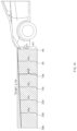
- FIG. 5 is an exemplary view illustrating that a number plate image is divided at equal intervals to be recognized according to the present disclosure
- FIG. 6 is an exemplary view illustrating that a height of a number plate frame from a ground surface is calculated by using a division result of a number plate image according to the present disclosure
- FIG. 7 is an exemplary view illustrating that heights of a number plate frame from a ground surface are calculated for various inter-vehicle distances according to the present disclosure
- FIG. 8 is an exemplary view illustrating a target line that represents an ideal light angle of a headlamp according to the present disclosure
- FIG. 9 is an exemplary view illustrating that a headlamp is excessively lowered
- FIG. 10 is an exemplary view illustrating that a headlamp is excessively raised
- FIG. 11 is an exemplary view illustrating a state, in which a target line is lowered as an inter-vehicle distance to a preceding vehicle becomes larger, is applied to a vehicle according to the present disclosure
- FIG. 13 is an exemplary view illustrating a state, in which a cutoff line of a headlamp is higher than a target line according to the present disclosure
- FIG. 14 is an exemplary view illustrating that a comparison result of a target line of a headlamp and a cutoff line of a headlamp is indicated on an output screen of a multifunctional camera (MFC) according to the present disclosure
- FIG. 15 is an exemplary view illustrating that a comparison result of a target line of a headlamp and a cutoff line of a headlamp is indicated on a windshield glass through a head up display (HUD) according to the present disclosure;
- HUD head up display
- FIG. 16 is a block diagram of a method for correcting a level of a headlamp according to the present disclosure.
- FIG. 17 is a flowchart illustrating a flow of determining whether correction of a level of a headlamp is necessary, and automatically correcting the level of the headlamp or requesting a driver for correction according to the present disclosure.
- vehicle or “vehicular” or other similar term as used herein is inclusive of motor vehicles in general such as passenger automobiles including sports utility vehicles (SUV), buses, trucks, various commercial vehicles, watercraft including a variety of boats and ships, aircraft, and the like, and includes hybrid vehicles, electric vehicles, combustion, plug-in hybrid electric vehicles, hydrogen-powered vehicles and other alternative fuel vehicles (e.g. fuels derived from resources other than petroleum).
- motor vehicles in general such as passenger automobiles including sports utility vehicles (SUV), buses, trucks, various commercial vehicles, watercraft including a variety of boats and ships, aircraft, and the like, and includes hybrid vehicles, electric vehicles, combustion, plug-in hybrid electric vehicles, hydrogen-powered vehicles and other alternative fuel vehicles (e.g. fuels derived from resources other than petroleum).
- SUV sports utility vehicles
- plug-in hybrid electric vehicles e.g. fuels derived from resources other than petroleum
- controller/control unit refers to a hardware device that includes a memory and a processor and is specifically programmed to execute the processes described herein.
- the memory is configured to store the modules and the processor is specifically configured to execute said modules to perform one or more processes which are described further below.
- control logic of the present disclosure may be embodied as non-transitory computer readable media on a computer readable medium containing executable program instructions executed by a processor, controller/control unit or the like.
- the computer readable mediums include, but are not limited to, ROM, RAM, compact disc (CD)-ROMs, magnetic tapes, floppy disks, flash drives, smart cards and optical data storage devices.
- the computer readable recording medium can also be distributed in network coupled computer systems so that the computer readable media is stored and executed in a distributed fashion, e.g., by a telematics server or a Controller Area Network (CAN).
- a telematics server or a Controller Area Network (CAN).
- CAN Controller Area Network
- FIG. 1 is a block diagram of an apparatus for correcting a level of a headlamp according to the present disclosure.
- an apparatus for correcting a level of a headlamp may include a number plate frame image extractor 100 configured to acquire a number plate frame image from an image of a preceding vehicle, which is captured by a camera provided in a vehicle, a number plate frame analyzer 200 configured to calculate an inter-vehicle distance to the preceding vehicle by using a transverse length of the number plate frame image, and divide a height standard of a rear area of the preceding vehicle, by which the number plate frame is spaced apart from a ground surface, into a plurality of unit areas, by using a longitudinal length of the number plate frame image, a headlamp level comparator 300 configured to compare a level of a cutoff line, at which light of the headlamp reaches the preceding vehicle with a level of a target line that is a preset ideal cutoff line, and determine a necessity for correction of the level of the headlamp, and a headlamp level corrector 400 configured to raise the level of the headlamp in response to determining that
- the number plate frame image extractor 100 may be configured to extract the number plate frame image from the image of the preceding vehicle, which is captured by the camera provided in the vehicle, and measure a size of the extracted number plate frame image.
- the standards of the number plates are determined according to countries, and as illustrated in FIG. 2 , the standard of the number plates of Korea is a transverse length of 520 mm and a longitudinal length of 110 mm.
- the size of the number plate frame image extracted in this way becomes smaller as an inter-vehicle distance, by which a preceding vehicle is spaced apart from a vehicle equipped with a camera, increases.
- the size of the image of the preceding vehicle, which is captured by the camera decreases as the inter-vehicle distance increases to 5 m, 10 m, and 15 m.
- the transverse length of a number plate frame image extracted from the image of the preceding vehicle also decreases as the inter-vehicle distance increases, and as illustrated in FIG. 4 , it is measured to be L 1 when the inter-vehicle distance is 5 meters, it is measured to be L 2 when the inter-vehicle distance is 10 meters, and it is measured to be
- the transverse length of the number plate frame image decreases in proportion to an increase of the inter-vehicle distance.
- the number plate frame analyzer 200 may include a distance calculator 210 configured to calculate the inter-vehicle distance to the preceding vehicle by using the transverse length of the number plate frame image, and a height standard divider 220 configured to equally divide the height standard of the number plate frame of the rear area of the preceding vehicle, by which the number plate frame is spaced apart from the ground surface, into the plurality of unit areas, by using the longitudinal length of the number plate frame image.
- a distance calculator 210 configured to calculate the inter-vehicle distance to the preceding vehicle by using the transverse length of the number plate frame image
- a height standard divider 220 configured to equally divide the height standard of the number plate frame of the rear area of the preceding vehicle, by which the number plate frame is spaced apart from the ground surface, into the plurality of unit areas, by using the longitudinal length of the number plate frame image.
- the distance calculator 210 may be configured to calculate the inter-vehicle distance to the preceding vehicle by comparing the transverse length of the number plate frame image, which is measured on the number plate frame image, with a transverse length of a standard of a number plate to derive a proportional relationship thereof.
- the inter-vehicle distance to the preceding vehicle may be calculated by using a degree, by which the transverse length of the number plate frame of the specific standard decreases.
- the distance calculator 210 may be configured to derive a level of a target line that is an ideal cutoff line of the headlamp at a calculated inter-vehicle distance by calculating the inter-vehicle distance to the preceding vehicle by using a proportional relationship, in which the transverse length of the number plate frame image decreases.
- the inter-vehicle distance to the preceding vehicle may be measured by a front radar sensor provided on the front side of the vehicle to detect whether an obstacle or a preceding vehicle is present and measure a distance to the obstacle or the preceding vehicle, and thus may be configured to correct the result of the inter-vehicle distance calculated by the distance calculator 210 and decrease an error of calculation of the distance.
- the height standard divider 220 may be configured to equally divide the longitudinal length of the number plate frame that appears on the number plate frame image into a plurality of unit areas having the same height as illustrated in FIG. 5 and divide the rear area of the preceding vehicle from a lower end of the number plate frame to the ground surface into heights of the unit areas as illustrated in FIG. 6 , and may be configured to calculate a sum of the heights of the unit areas as the height standard (HS) of the number plate frame. Then, the height standard, as illustrated in FIG. 6 , refers to a height from the ground surface to the lower end of the number plate frame.
- a number plate frame having a longitudinal length of 110 mm may be divided into eleven unit areas having the same height of 10 mm.
- the longitudinal length of the number plate frame may be different according to the standards of the number plates of the countries, and it is apparent that the heights of the unit area and the number of the unit areas that divide the longitudinal length of the number plate frame may be set differently without being limited to the example illustrated in FIG. 5 .
- the height standard divider 220 may be configured to calculate a proportional relationship of the unit areas, in which the longitudinal length of the number plate frame is a fixed reference, without calculating the longitudinal length of the number plate frame by using a proportional relationship, in which the longitudinal length of the number plate frame increases relatively according to a change in the inter-vehicle distance to the preceding vehicle.
- the height standard (HS) may be calculated in the same way when the inter-vehicle distances are 15 m, 10 m, and 5 m, without being influenced by an increment of the size of the image of the preceding vehicle, which is captured by the camera, and an increment of the size of the number plate frame image.
- the height standard that represents the height from the ground surface to the lower end of the number plate frame is calculated to be N unit area (here, N is an arbitrary integer) when the inter-vehicle distance is 10 m
- the height standard may be calculated to be N unit areas in the same way even when the inter-vehicle distances are 15 m and 5 m.
- the height standard is stably calculated without being influenced by the inter-vehicle distance, a change in the level of the cutoff line of the headlamp due to a relative change of the level of the cutoff line may be recognized, for example, when the front surface of the vehicle is raised or pressed and lowered due to passengers or the weight and a disposition of loaded cargo.
- the headlamp level comparator 300 may be configured to determine whether the cutoff line of the headlamp is lower or higher than the target line due to the weights of the passengers on board or the loaded cargo or a change of the posture of the vehicle, such as a change in the locations thereof, by comparing the level of the cutoff line, at which the light of the headlamp reaches the preceding vehicle with the level of the target line. To achieve this, the headlamp level comparator 300 may be configured to determine to which unit area of the rear area of the preceding vehicle divided into the plurality of unit areas the level of the cutoff line, at which the light of the headlamp reaches the preceding vehicle, corresponds, to calculate the height standard (HS). The location of the cutoff line of the headlamp may be determined by a front camera including a multifunctional camera (MFC) provided in the vehicle in advance, and may be compared with the level of the target line calculated in advance according to the inter-vehicle distance.
- MFC multifunctional camera
- the headlamp level comparator 300 may be configured to calculate to which location of the rear area of the preceding vehicle the level of the target line that is an ideal cutoff line of the headlamp corresponds. Accordingly, the levels may be compared by recognizing the height standard of the rear area of the preceding vehicle with a set of the unit areas obtained by equally dividing the number plate frame of the preceding vehicle into a specific size and determining to which unit area of the plurality of unit areas that form the rear area of the preceding vehicle the cutoff line and the target line correspond while the locations of the cutoff line of the headlamp and the target line not being compared with numerical feature values.
- FIG. 8 it is defined as an ideal state when light irradiated at the height H 1 of the headlamp installed in the vehicle is set to face the height h 2 obtained by subtracting 100 mm from the height h 1 of the headlamp at a location of the front side by 10 m. Accordingly, an OEM that manufactures a headlamp of a vehicle initially sets the headlamp such that the level of the cutoff line of the headlamp maintains the state.
- the line that faces the height of h 2 (that is, a height of h 1 -100 mm) at a point of the front side by 10 m may be set to the ideal cutoff line that is the target line.
- the target line may be indicated by a straight line that faces the lower side from the headlamp as illustrated in FIGS. 9 and 10 while forming an angle of 0.57° calculated in Equation 1 that represents an initial setting condition.
- Equation 1 h 1 -h 2 is 100 mm when the inter-vehicle distance is 10 m according to the general initial setting condition for setting the target line.
- the light angle of the headlamp that is initially set to form the target line may be changed such that the cutoff line of the headlamp becomes lower than the target line due to various causes, such as when the front side of the vehicle is heavier than the rear side thereof.
- the cutoff line of the headlamp may become lower than the target line as the inter-vehicle distance to the preceding vehicle increases, and this may hamper the driver from securing a sight during nighttime driving.
- the front side of the vehicle may be raised such that the cutoff line of the headlamp becomes higher than the target line.
- the cutoff line of the headlamp becomes higher than the target line as the inter-vehicle distance to the preceding vehicle increases, and thus a sight of the preceding vehicle or the driver of the vehicle that travels on a lane on an opposite side may be obstructed.
- FIGS. 9 and 10 illustrate that the heights of the target lines become proportionally lower (having an inclination of about 0.57°) from h a to h d as the inter-vehicle distance increases by indicating the heights of the target lines calculated when the inter-vehicle distance (h x ) to the preceding vehicle is 5 m, 10 m, 15 m, 20 m, and 25 m, respectively, to “a” when x (here, x is the inter-vehicle distance) is 5 m, “b” when x is 15 m, “c” when x is 20 m, and “d” when x is 25 in.
- a point corresponding to the inter-vehicle distance of 0 m, that is, the installation height of the headlamp is indicated by h 1
- the height of the target line at a point corresponding to the inter-vehicle distance of 10 m that represents the initial setting condition for generating the target line is indicated by h 2 .
- the target line is formed at a location of h a that is closer to the height standard below the number plate, it may be identified on the divided image of the height of the preceding vehicle corresponding to the inter-vehicle distance of 10 m, the target line is formed at a location of h 2 that is lower than h a , and on the divided image of the height of the preceding vehicle corresponding to the inter-vehicle distance of 15 m the target line is formed at a location of h b that is lower than h 2 .
- FIG. 11 illustrates that the target line is indicated on the image of the preceding vehicle while the interval of the inter-vehicle distances is 5 m
- the interval of the inter-vehicle distances may be variously set.
- the headlamp level comparator 300 as illustrated in FIG. 12 , may be configured to recognize the location of the target line determined with reference to the inter-vehicle distance calculated by using the transverse length of the number plate measured on the number plate image by the distance calculator with the locations of the unit areas that divide the height standard at an equal interval on the image of the preceding vehicle.
- the headlamp level corrector 400 may be configured to perform a correction of raising the level of the headlamp such that the cutoff line reaches the height of the target line when the level of the cutoff line is lower than the target line and to perform a correction of lowering the level of the headlamp such that the cutoff line reaches the height of the target line when the level of the cutoff line is higher than the target line.
- the headlamp leveling device (HLLD) of an automatic correction type when the headlamp leveling device (HLLD) of an automatic correction type is provided, a primary correction of the lighting angle of the headlamp is promptly performed according to a result recognized by a sensor and the like provided therein, and then, the lighting angle of the headlamp may be additionally raised or lowered to reach the target line by the headlamp level corrector 400 .
- HLLD headlamp leveling device
- an embodiment of the present disclosure may further include a headlamp level indicator 500 that allows the driver to intuitively recognize whether it is necessary to correct the lighting angle of the headlamp and provides information on a correction direction and a correction degree together by outputting a front image including the preceding vehicle on the display unit provided in the vehicle and indicating the target line and the cutoff line together on the image of the preceding vehicle in a superimposition way.
- the headlamp level indicator 500 as illustrated in FIG. 14 , may be configured to output or indicate the image of the preceding vehicle, the cutoff line, and the target line together on the display unit that displays the image of the multifunctional camera (MFC).
- the inter-vehicle distance to the preceding vehicle may be calculated using a degree, by which the transverse length of the number plate frame of the specific standard decreases. Accordingly, in the distance calculating operation S 210 , a level of a target line that is an ideal cutoff line of the headlamp from a calculated inter-vehicle distance may be derived by calculating the inter-vehicle distance to the preceding vehicle by using a proportional relationship, in which the transverse length of the number plate frame image decreases.
- an error in calculation of the inter-vehicle distance to the preceding vehicle may be decreased by correcting a result of the inter-vehicle distance calculated in the distance calculating operation S 210 by using the inter-vehicle distance measured by a front radar sensor provided in the vehicle.
- the height standard dividing operation 220 the longitudinal length of the number plate frame that appears on the number plate frame image into a plurality of unit areas having the same height may be equally divided and then the rear area of the preceding vehicle from a lower end of the number plate frame to the ground surface into heights of the unit areas may be divided into heights of the unit areas, and a sum of the heights of the unit areas may be calculated as the height standard (HS) of the number plate frame.
- the height standard (HS) refers to a height from the ground surface to the lower end of the number plate frame.
- the longitudinal length of the number plate frame may be different according to the standards of the number plates of the countries, and it is apparent that the heights of the unit area and the number of the unit areas that divide the longitudinal length of the number plate frame may be variously set without being limited to the specific embodiment.
- the headlamp level comparing operation S 300 it may be determined whether the cutoff line of the headlamp is lower or higher than the target line due to a change of the posture of the vehicle and the like by comparing the level of the cutoff line, at which the light of the headlamp reaches the preceding vehicle with the level of the target line
- the headlamp level comparing operation S 300 it may be determined to which unit area of the rear area of the preceding vehicle divided into the plurality of unit areas to calculate the height standard (HS) the level of the cutoff line, at which the light of the headlamp reaches the preceding vehicle, corresponds. Further, in the headlamp level comparing operation S 300 , it may be calculated to which location of the rear area of the preceding vehicle the level of the target line that is an ideal cutoff line of the headlamp corresponds.
- HS height standard
- the levels may be compared by recognizing the height standard of the rear area of the preceding vehicle with a set of the unit areas obtained by equally dividing the number plate frame of the preceding vehicle into a specific size and determining to which unit area of the plurality of unit areas that form the rear area of the preceding vehicle the cutoff line and the target line correspond while the locations of the cutoff line of the headlamp and the target line not being compared with numerical feature values.
- a control to perform a correction of raising the level of the headlamp such that the cutoff line reaches the height of the target line when the level of the cutoff line is lower than the target line and to perform a correction of lowering the level of the headlamp such that the cutoff line reaches the height of the target line when the level of the cutoff line is higher than the target line may be performed.
- a correction of raising or lowering the level of the headlamp such that the cutoff line of the headlamp reaches the target line may be automatically performed when a headlamp leveling device (HLLD) of an automatic correction type, which may automatically adjust the level of the headlamp, is provided, whereby the light of the headlamp may be minimized from causing inconvenience to driving of the preceding vehicle or the vehicle that travels on an opposite lane while a sight of the driver is stably secured.
- HLLD headlamp leveling device
- the headlamp leveling device (HLLD) of an automatic correction type when the headlamp leveling device (HLLD) of an automatic correction type is provided, a primary correction of the lighting angle of the headlamp is promptly performed according to a result recognized by a sensor and the like provided therein, and then, the lighting angle of the headlamp may be additionally raised or lowered to reach the target line in the headlamp level correcting operation S 500 .
- an indication such as a warning that requests performance of a correction of raising or lowering the level of the headlamp may be output such that the cutoff line of the headlamp reaches the target line in a form of a voice of a message including a popup window may be recognized by the driver when the headlamp leveling device (HLLD) of a switch type, in which adjustment of the level of the headlamp depends on manipulation by the driver is provided.
- HLLD headlamp leveling device
- the present disclosure may include a headlamp level indicating operation S 400 of allowing the driver to intuitively recognize whether it is necessary to correct the lighting angle of the headlamp and providing information on a correction direction and a correction degree together by indicating a front image including the preceding vehicle on the display unit provided in the vehicle and indicating the target line and the cutoff line together on the image of the preceding vehicle in a superimposition way whereby the driver may recognize the determination result in the headlamp level comparing operation S 300 . Accordingly, in the headlamp level indicating operation S 400 , the image of the preceding vehicle, the cutoff line, and the target line may be indicated together on the display unit that displays the image of the multifunctional camera (MFC).
- MFC multifunctional camera
- the image of the preceding vehicle which is captured by the multifunctional camera (MFC) provided in the vehicle, the cutoff line, and the target line may be indicated together on the windshield glass when data that may be visually recognized by the driver may be output on a windshield glass through ahead-up display (HUD) provided in the vehicle. Then, in a HUD screen, a distance, by which the cutoff line has to be raised or lowered to follow the height of the target line, may be calculated and indicated or output together.
- MFC multifunctional camera
- HUD ahead-up display
- the level comparison result of the current cutoff line of the headlamp and the target line may be provided to allow the driver to visually recognize the result through the screen of the multifunctional camera (MFC) or the head-up display (HUD), convenience of manipulation of the headlamp may be improved during nighttime driving of the vehicle. Furthermore, since the comparison of the cutoff line of the headlamp and the target line and the following control may be possible based on the image of the preceding vehicle captured by the camera provided in the vehicle in advance, additional costs for the execution may be minimized and the present disclosure may be applied to the vehicle more easily.
- MFC multifunctional camera
- HUD head-up display
- FIG. 17 it may be determined whether a preceding vehicle is present on a front side of the vehicle, a lighting angle of the headlamp may be maintained at a previous value when no preceding vehicle is present (No), a number plate frame image may be extracted from an image of the preceding vehicle, which is captured by a camera provided in the vehicle when a preceding vehicle is present, and then a transverse length and a longitudinal length of the number plate frame image may be measured and analyzed.
- an inter-vehicle distance to the preceding vehicle may be calculated by using a decrease ratio of the transverse length of the number plate frame and the transverse length of the standard of the actual number plate frame. Then, the inter-vehicle distance calculated by using the proportional relationship of the number plate frame image may be compared with the inter-vehicle distance to the preceding vehicle recognized by the measured value of the front radar sensor provided in the vehicle.
- the longitudinal length of the number plate frame image may be equally divided into a plurality of unit areas having a specific height to calculate the level of the target line from the specified inter-vehicle distance.
- the rear area of the preceding vehicle may be divided into heights of unit areas to calculate the height of the area from a lower end of the number plate frame to a ground surface with a sum of the heights of the unit areas. Thereafter, after the level of the target line is calculated from the specified inter-vehicle distance, it may be determined which location of the plurality of unit areas that form the rear area of the preceding vehicle corresponds to the level of the target line.
- the vehicle may be calculated which location of the plurality of unit areas that form the rear area of the preceding vehicle the level of the cutoff line, at which the light irradiated from the headlamp of the vehicle reaches the rear area of the preceding vehicle, reaches.
- HUD head-up display
- convenience of intuitive recognition of the driver may be achieved by indicating a comparison result of the cutoff line of the headlamp and the target line.
- recognition of the driver may be achieved by indicating the comparison result of the cutoff line of the headlamp and the target line on the screen of the multifunctional camera (MFC).
- the vehicle includes an automatic correction device that may automatically correct the lighting angle of the headlamp (Yes), the lighting angle of the headlamp may be automatically raised or lowered until the cutoff line of the headlamp reaches the level of the target line.
- the driver may be informed that the correction is made, through a popup image or a voice.
- the driver may be informed by a popup message or a voice that requests the driver to adjust the lighting angle of the headlamp such that the lighting angle of the headlamp is raised or lowered.
- the lighting angle of the headlamp may be manually corrected by manipulating a switch and the like by the driver such that the cutoff line of the headlamp reaches the level of the target line.
- the lighting angle of the headlamp may be changed while the front side of the vehicle is pressed or raised, and it may be determined whether it is necessary to correct the lighting angle of the headlamp while determining whether a preceding vehicle is present again.
- the level of the cutoff line of the headlamp may be more precisely and conveniently corrected by comparing the cutoff line of the headlamp and the target line based on the image of the preceding vehicle, which is captured by the camera provided in the vehicle and adjust the level of the headlamp such that the level of the headlamp follows the level of the target line, and thus minimizing addition of sensors and minimizing an increase of costs.
- the level comparison result of the current cutoff line of the headlamp and the target line may be provided so that the driver may visually recognize the result through the screen of the multifunctional camera (MFC) or the head-up display (HUD), the driver may intuitively determine a correction of the level of the headlamp, thereby improving convenience of manipulation of the headlamp during nighttime driving.
- the present disclosure may provide various effects that are directly or indirectly recognized.
Landscapes
- Engineering & Computer Science (AREA)
- Mechanical Engineering (AREA)
- Physics & Mathematics (AREA)
- General Physics & Mathematics (AREA)
- Remote Sensing (AREA)
- Radar, Positioning & Navigation (AREA)
- Combustion & Propulsion (AREA)
- Chemical & Material Sciences (AREA)
- Transportation (AREA)
- Theoretical Computer Science (AREA)
- Multimedia (AREA)
- Computer Networks & Wireless Communication (AREA)
- Human Computer Interaction (AREA)
- Electromagnetism (AREA)
- Computer Vision & Pattern Recognition (AREA)
- Optics & Photonics (AREA)
- Lighting Device Outwards From Vehicle And Optical Signal (AREA)
Abstract
Description
Claims (20)
Applications Claiming Priority (2)
| Application Number | Priority Date | Filing Date | Title |
|---|---|---|---|
| KR10-2021-0042173 | 2021-03-31 | ||
| KR1020210042173A KR20220135900A (en) | 2021-03-31 | 2021-03-31 | Apparatus for level correction of head lamp and method thereof |
Publications (2)
| Publication Number | Publication Date |
|---|---|
| US20220314869A1 US20220314869A1 (en) | 2022-10-06 |
| US12059995B2 true US12059995B2 (en) | 2024-08-13 |
Family
ID=83405089
Family Applications (1)
| Application Number | Title | Priority Date | Filing Date |
|---|---|---|---|
| US17/479,512 Active 2043-04-18 US12059995B2 (en) | 2021-03-31 | 2021-09-20 | Apparatus and method for correcting level of headlamp |
Country Status (3)
| Country | Link |
|---|---|
| US (1) | US12059995B2 (en) |
| KR (1) | KR20220135900A (en) |
| CN (1) | CN115139893B (en) |
Families Citing this family (1)
| Publication number | Priority date | Publication date | Assignee | Title |
|---|---|---|---|---|
| JP2024086127A (en) * | 2022-12-16 | 2024-06-27 | トヨタ自動車株式会社 | Display Control Device |
Citations (4)
| Publication number | Priority date | Publication date | Assignee | Title |
|---|---|---|---|---|
| US9135709B2 (en) * | 2013-02-28 | 2015-09-15 | Fujifilm Corporation | Vehicle-to-vehicle distance calculation apparatus and method |
| US20180334083A1 (en) * | 2017-05-19 | 2018-11-22 | Stanley Electric Co., Ltd. | Control device for vehicular lamp and vehicle lighting system |
| US10311722B2 (en) * | 2014-04-14 | 2019-06-04 | Licensys Australasia Pty Ltd | Vehicle identification and/or monitoring system |
| US20220201253A1 (en) * | 2020-12-22 | 2022-06-23 | Axis Ab | Camera and a method therein for facilitating installation of the camera |
Family Cites Families (5)
| Publication number | Priority date | Publication date | Assignee | Title |
|---|---|---|---|---|
| DE19513554A1 (en) * | 1995-04-10 | 1996-10-17 | Bayerische Motoren Werke Ag | Device for adjusting the headlight range of a motor vehicle headlight |
| JP4614347B2 (en) * | 2005-06-23 | 2011-01-19 | 株式会社小糸製作所 | Vehicle lamp |
| FR3021605B1 (en) * | 2014-06-03 | 2016-05-27 | Valeo Vision | METHOD AND SYSTEM FOR CORRECTING THE ORIENTATION OF THE PROJECTERS OF A MOTOR VEHICLE |
| CN105667384B (en) * | 2014-11-19 | 2018-03-30 | 上海汽车集团股份有限公司 | Vehicle head lamp dynamic level adjusting method and device |
| DE102015120204A1 (en) * | 2015-11-23 | 2017-05-24 | Hella Kgaa Hueck & Co. | Method for operating at least one headlight of a vehicle |
-
2021
- 2021-03-31 KR KR1020210042173A patent/KR20220135900A/en active Pending
- 2021-09-20 US US17/479,512 patent/US12059995B2/en active Active
- 2021-10-08 CN CN202111171039.6A patent/CN115139893B/en active Active
Patent Citations (4)
| Publication number | Priority date | Publication date | Assignee | Title |
|---|---|---|---|---|
| US9135709B2 (en) * | 2013-02-28 | 2015-09-15 | Fujifilm Corporation | Vehicle-to-vehicle distance calculation apparatus and method |
| US10311722B2 (en) * | 2014-04-14 | 2019-06-04 | Licensys Australasia Pty Ltd | Vehicle identification and/or monitoring system |
| US20180334083A1 (en) * | 2017-05-19 | 2018-11-22 | Stanley Electric Co., Ltd. | Control device for vehicular lamp and vehicle lighting system |
| US20220201253A1 (en) * | 2020-12-22 | 2022-06-23 | Axis Ab | Camera and a method therein for facilitating installation of the camera |
Non-Patent Citations (1)
| Title |
|---|
| Hossan, Md Tanvir, et al. "A new vehicle localization scheme based on combined optical camera communication and photogrammetry." Mobile Information Systems 2018 (2018): 1-14. * |
Also Published As
| Publication number | Publication date |
|---|---|
| KR20220135900A (en) | 2022-10-07 |
| CN115139893B (en) | 2025-08-08 |
| US20220314869A1 (en) | 2022-10-06 |
| CN115139893A (en) | 2022-10-04 |
Similar Documents
| Publication | Publication Date | Title |
|---|---|---|
| CN111696160B (en) | Automatic calibration method and equipment for vehicle-mounted camera and readable storage medium | |
| US12277730B2 (en) | System and method of calibrating an optical sensor mounted on board of a vehicle | |
| US8279280B2 (en) | Lane departure warning method and system using virtual lane-dividing line | |
| US9135709B2 (en) | Vehicle-to-vehicle distance calculation apparatus and method | |
| US9152887B2 (en) | Object detection device, object detection method, and object detection program | |
| EP1891580B1 (en) | Method and a system for detecting a road at night | |
| US20140244111A1 (en) | System and method for monitoring vehicle speed and driver notification | |
| US20120256874A1 (en) | Operation apparatus | |
| JP2010085186A (en) | Calibration device for on-vehicle camera | |
| WO2021159913A1 (en) | Adas system calibration guiding method and apparatus, and vehicle diagnosis device | |
| US20150178902A1 (en) | Image processing apparatus and image processing method for removing rain streaks from image data | |
| US20150098622A1 (en) | Image processing method and system of around view monitoring system | |
| US12123801B2 (en) | ADAS calibration system for calibrating at least one headlamp of a vehicle | |
| US20170168561A1 (en) | Head up display automatic correction method and correction system | |
| US12059995B2 (en) | Apparatus and method for correcting level of headlamp | |
| KR20210005605A (en) | Online evaluation of camera specific parameters | |
| US10974658B2 (en) | Image display control device | |
| CN110568412A (en) | Method for calibrating sensor assembly | |
| CN115140029B (en) | A method and device for detecting safety capability of an autonomous driving vehicle | |
| US20220402494A1 (en) | A method for evaluating a minimum breaking distance of a vehicle and vehicle | |
| CN111409553A (en) | ADAS display device and method | |
| KR101056285B1 (en) | Method and system for setting autonomous correction and lane departure warning point of vehicle camera | |
| US9381853B2 (en) | Control system and method for auto-light | |
| US20240013555A1 (en) | Image based reference position identification and use for camera monitoring system | |
| US12503114B2 (en) | Apparatus and method for controlling automatic lane change of vehicle |
Legal Events
| Date | Code | Title | Description |
|---|---|---|---|
| AS | Assignment |
Owner name: KIA CORPORATION, KOREA, REPUBLIC OF Free format text: ASSIGNMENT OF ASSIGNORS INTEREST;ASSIGNOR:LEE, JAE WOONG;REEL/FRAME:057537/0032 Effective date: 20210809 Owner name: HYUNDAI MOTOR COMPANY, KOREA, REPUBLIC OF Free format text: ASSIGNMENT OF ASSIGNORS INTEREST;ASSIGNOR:LEE, JAE WOONG;REEL/FRAME:057537/0032 Effective date: 20210809 |
|
| FEPP | Fee payment procedure |
Free format text: ENTITY STATUS SET TO UNDISCOUNTED (ORIGINAL EVENT CODE: BIG.); ENTITY STATUS OF PATENT OWNER: LARGE ENTITY |
|
| STPP | Information on status: patent application and granting procedure in general |
Free format text: DOCKETED NEW CASE - READY FOR EXAMINATION |
|
| STPP | Information on status: patent application and granting procedure in general |
Free format text: NOTICE OF ALLOWANCE MAILED -- APPLICATION RECEIVED IN OFFICE OF PUBLICATIONS |
|
| ZAAA | Notice of allowance and fees due |
Free format text: ORIGINAL CODE: NOA |
|
| ZAAB | Notice of allowance mailed |
Free format text: ORIGINAL CODE: MN/=. |
|
| STPP | Information on status: patent application and granting procedure in general |
Free format text: PUBLICATIONS -- ISSUE FEE PAYMENT VERIFIED |
|
| STCF | Information on status: patent grant |
Free format text: PATENTED CASE |