US120560A - Improvement in sulky attachments for plows - Google Patents
Improvement in sulky attachments for plows Download PDFInfo
- Publication number
- US120560A US120560A US120560DA US120560A US 120560 A US120560 A US 120560A US 120560D A US120560D A US 120560DA US 120560 A US120560 A US 120560A
- Authority
- US
- United States
- Prior art keywords
- plows
- improvement
- plow
- lever
- sulky
- Prior art date
- Legal status (The legal status is an assumption and is not a legal conclusion. Google has not performed a legal analysis and makes no representation as to the accuracy of the status listed.)
- Expired - Lifetime
Links
- 238000010276 construction Methods 0.000 description 2
Images
Classifications
-
- A—HUMAN NECESSITIES
- A01—AGRICULTURE; FORESTRY; ANIMAL HUSBANDRY; HUNTING; TRAPPING; FISHING
- A01B—SOIL WORKING IN AGRICULTURE OR FORESTRY; PARTS, DETAILS, OR ACCESSORIES OF AGRICULTURAL MACHINES OR IMPLEMENTS, IN GENERAL
- A01B63/00—Lifting or adjusting devices or arrangements for agricultural machines or implements
- A01B63/02—Lifting or adjusting devices or arrangements for agricultural machines or implements for implements mounted on tractors
- A01B63/04—Hand devices; Hand devices with mechanical accumulators, e.g. springs
Definitions
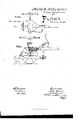
- Figure l of the drawing is a plan view of our invention.
- Fig. 2 is a vertical section of the same.
- This invention has relation to an improved snlky attachment to plows; and consists in the application of novel devices, hereinafter described, for controlling both the front and rear ends of the plow-beam, in order to regulate the depth of the furrows.
- This invention has also reference to certain peculiarities of the Wheels and axle, so that a right or lefthand plow may be used at pleasure.
- A represents the axle, raised in the middle part B B', the wheels, of diii'erent diameters. The smaller wheel runs in one of the completed furrows to guide the plow.
- G C' shows a pair of arms pivoted to the vertical parts of the axle A and projecting to the rear, where they are connected by the transverse bar D, which may be a continuation of the bars O C'.
- E represents the longitudinal plowbeam, supported in the rear to the bar D by a hinge, F, the swinging plate of which is rigidly secured to said bar by bolts.
- E' is the plow.
- the bar C' extends forward of the axle A, and is formed into a foot-piece, c, by pressing upon which the plow-beam and plows are elevated.
- Gr represents the draft-beam, to which the curved rack H and double-armed or elbow-lever H' are pivoted
- the rear arm of this lever is swiveled by a transverse pin, h, to a long vertical loop, I, to which the forward end of the plow-beam is hung by an eye-bolt, i.
- the teeth of the rack H face the lever H', as shown in the drawing.
- the object of the lever H' is to raise the points of the plow, and by this means regulate the depth of a furrow.
- the foot-lever C is intended for the purpose of raising the plow entirely out of the furrow or out of contact with the ground.
- the plow when raised by the lever H', is kept in place by the rack H, which is made to engage with the pin hat the proper point of elevation.
- K represents the drivers seat supported in an elevated position upon a standard, K'.
- the devices herein described are simple, will work easily, and they may be made of sufficient strength to bear heavy plows without being of inconvenient size.
Landscapes
- Life Sciences & Earth Sciences (AREA)
- Engineering & Computer Science (AREA)
- Mechanical Engineering (AREA)
- Soil Sciences (AREA)
- Environmental Sciences (AREA)
- Soil Working Implements (AREA)
Description
UNITED STATES PATENT OFFICE.
JOHN WORRELL AND JAMES H. RYNERSON, OF CLAYTON, INDIANA.
IMPROVEMENT IN SULKV ATTACHMENTS FOR PLOWS.
To all whom it may concern:
Be it known that we, JOHN WORRELL and J AMEs H. RYNERsoN, of Clayton, in the county of Hendricks and State of Indiana, have invented a new and valuable Improvement in Sulky Attachments for Plows 3 and we do hereby declare that the following is a Jfull, clear, and exact description of the construction and operation of the same, reference being had to the annexed drawing making a part of this specication, and to the letters and igures of reference marked thereon.
Figure l of the drawing is a plan view of our invention. Fig. 2 is a vertical section of the same.
This invention has relation to an improved snlky attachment to plows; and consists in the application of novel devices, hereinafter described, for controlling both the front and rear ends of the plow-beam, in order to regulate the depth of the furrows. This invention has also reference to certain peculiarities of the Wheels and axle, so thata right or lefthand plow may be used at pleasure.
In the accompanying drawing illustrating the nature of these improvements, A represents the axle, raised in the middle part B B', the wheels, of diii'erent diameters. The smaller wheel runs in one of the completed furrows to guide the plow. G C' shows a pair of arms pivoted to the vertical parts of the axle A and projecting to the rear, where they are connected by the transverse bar D, which may be a continuation of the bars O C'. E represents the longitudinal plowbeam, supported in the rear to the bar D by a hinge, F, the swinging plate of which is rigidly secured to said bar by bolts. E' is the plow. The bar C' extends forward of the axle A, and is formed into a foot-piece, c, by pressing upon which the plow-beam and plows are elevated.
Gr represents the draft-beam, to which the curved rack H and double-armed or elbow-lever H' are pivoted The rear arm of this lever is swiveled by a transverse pin, h, to a long vertical loop, I, to which the forward end of the plow-beam is hung by an eye-bolt, i. The teeth of the rack H face the lever H', as shown in the drawing. The object of the lever H' is to raise the points of the plow, and by this means regulate the depth of a furrow. The foot-lever C is intended for the purpose of raising the plow entirely out of the furrow or out of contact with the ground. The plow, when raised by the lever H', is kept in place by the rack H, which is made to engage with the pin hat the proper point of elevation. K represents the drivers seat supported in an elevated position upon a standard, K'.
The devices herein described are simple, will work easily, and they may be made of sufficient strength to bear heavy plows without being of inconvenient size.
The sulky-attachment for plows above described is intended to be an improvement upon our patents of July 26, 1870, and March 28, 1871, and the p articular improvements consist mainly in the construction of the curved rack H and hinge F above mentioned.
Having fully described our invention, We claim- The curved rack H and hinge F, in combination with the lever H', beam E, bar D, and arms OC', when constructed and arranged substantially as and for the purpose specified.
In testimony that we claim the above we have hereunto subscribed our names in the presence of two witnesses.
JOHN WORRELL.
JAMES H. RYNERSON.
Witnesses G. W. MGGLURE, W. A. ROGERS. (114)
Publications (1)
| Publication Number | Publication Date |
|---|---|
| US120560A true US120560A (en) | 1871-10-31 |
Family
ID=2190005
Family Applications (1)
| Application Number | Title | Priority Date | Filing Date |
|---|---|---|---|
| US120560D Expired - Lifetime US120560A (en) | Improvement in sulky attachments for plows |
Country Status (1)
| Country | Link |
|---|---|
| US (1) | US120560A (en) |
-
0
- US US120560D patent/US120560A/en not_active Expired - Lifetime
Similar Documents
| Publication | Publication Date | Title |
|---|---|---|
| US120560A (en) | Improvement in sulky attachments for plows | |
| US131404A (en) | Improvement in cultivators | |
| US49667A (en) | Improvement in cultivators | |
| US55381A (en) | Improvement in cultivators | |
| US135912A (en) | Improvement in cultivators | |
| US111366A (en) | Improvement in sulky-plows | |
| US118567A (en) | Improvement in sulky-cultivators | |
| US112079A (en) | Improvement in combined gang-plows and cultivators | |
| US124480A (en) | Improvement in gang-plows | |
| US56295A (en) | Improvement in cultivators | |
| US47989A (en) | Improvement in gang-plows | |
| US132842A (en) | Improvement in gang-plows | |
| US467382A (en) | Cultivator | |
| US45833A (en) | Improvement in cultivators | |
| US119192A (en) | Improvement in gang-plows | |
| US387484A (en) | Sulky-plow | |
| US193983A (en) | Improvement in plows | |
| US111226A (en) | Improvement in gang-plows | |
| US345068A (en) | Feedeeigk theodoee millee | |
| US48696A (en) | Improvement in gang-plows | |
| US58788A (en) | Improvement in gang and subsoil plows | |
| US84970A (en) | Improvement in flows | |
| US41086A (en) | Improvement in cultivators | |
| US795709A (en) | Plow. | |
| US206989A (en) | Improvement in sulky-plows |