US12055566B2 - Locking current transformer - Google Patents
Locking current transformer Download PDFInfo
- Publication number
- US12055566B2 US12055566B2 US17/990,549 US202217990549A US12055566B2 US 12055566 B2 US12055566 B2 US 12055566B2 US 202217990549 A US202217990549 A US 202217990549A US 12055566 B2 US12055566 B2 US 12055566B2
- Authority
- US
- United States
- Prior art keywords
- core
- current transformer
- housing
- distal
- lock
- Prior art date
- Legal status (The legal status is an assumption and is not a legal conclusion. Google has not performed a legal analysis and makes no representation as to the accuracy of the status listed.)
- Active
Links
Images


Classifications
-
- H—ELECTRICITY
- H01—ELECTRIC ELEMENTS
- H01F—MAGNETS; INDUCTANCES; TRANSFORMERS; SELECTION OF MATERIALS FOR THEIR MAGNETIC PROPERTIES
- H01F38/00—Adaptations of transformers or inductances for specific applications or functions
- H01F38/20—Instruments transformers
- H01F38/22—Instruments transformers for single phase AC
- H01F38/28—Current transformers
- H01F38/30—Constructions
-
- G—PHYSICS
- G01—MEASURING; TESTING
- G01R—MEASURING ELECTRIC VARIABLES; MEASURING MAGNETIC VARIABLES
- G01R15/00—Details of measuring arrangements of the types provided for in groups G01R17/00 - G01R29/00, G01R33/00 - G01R33/26 or G01R35/00
- G01R15/14—Adaptations providing voltage or current isolation, e.g. for high-voltage or high-current networks
- G01R15/18—Adaptations providing voltage or current isolation, e.g. for high-voltage or high-current networks using inductive devices, e.g. transformers
- G01R15/186—Adaptations providing voltage or current isolation, e.g. for high-voltage or high-current networks using inductive devices, e.g. transformers using current transformers with a core consisting of two or more parts, e.g. clamp-on type
-
- G—PHYSICS
- G01—MEASURING; TESTING
- G01R—MEASURING ELECTRIC VARIABLES; MEASURING MAGNETIC VARIABLES
- G01R19/00—Arrangements for measuring currents or voltages or for indicating presence or sign thereof
- G01R19/0092—Arrangements for measuring currents or voltages or for indicating presence or sign thereof measuring current only
-
- H—ELECTRICITY
- H01—ELECTRIC ELEMENTS
- H01F—MAGNETS; INDUCTANCES; TRANSFORMERS; SELECTION OF MATERIALS FOR THEIR MAGNETIC PROPERTIES
- H01F19/00—Fixed transformers or mutual inductances of the signal type
- H01F19/04—Transformers or mutual inductances suitable for handling frequencies considerably beyond the audio range
-
- H—ELECTRICITY
- H01—ELECTRIC ELEMENTS
- H01F—MAGNETS; INDUCTANCES; TRANSFORMERS; SELECTION OF MATERIALS FOR THEIR MAGNETIC PROPERTIES
- H01F27/00—Details of transformers or inductances, in general
- H01F27/02—Casings
-
- H—ELECTRICITY
- H01—ELECTRIC ELEMENTS
- H01F—MAGNETS; INDUCTANCES; TRANSFORMERS; SELECTION OF MATERIALS FOR THEIR MAGNETIC PROPERTIES
- H01F27/00—Details of transformers or inductances, in general
- H01F27/02—Casings
- H01F27/027—Casings specially adapted for combination of signal type inductors or transformers with electronic circuits, e.g. mounting on printed circuit boards
-
- H—ELECTRICITY
- H01—ELECTRIC ELEMENTS
- H01F—MAGNETS; INDUCTANCES; TRANSFORMERS; SELECTION OF MATERIALS FOR THEIR MAGNETIC PROPERTIES
- H01F27/00—Details of transformers or inductances, in general
- H01F27/06—Mounting, supporting or suspending transformers, reactors or choke coils not being of the signal type
-
- H—ELECTRICITY
- H01—ELECTRIC ELEMENTS
- H01F—MAGNETS; INDUCTANCES; TRANSFORMERS; SELECTION OF MATERIALS FOR THEIR MAGNETIC PROPERTIES
- H01F27/00—Details of transformers or inductances, in general
- H01F27/24—Magnetic cores
-
- H—ELECTRICITY
- H01—ELECTRIC ELEMENTS
- H01F—MAGNETS; INDUCTANCES; TRANSFORMERS; SELECTION OF MATERIALS FOR THEIR MAGNETIC PROPERTIES
- H01F38/00—Adaptations of transformers or inductances for specific applications or functions
-
- H05K5/0004—
-
- H—ELECTRICITY
- H05—ELECTRIC TECHNIQUES NOT OTHERWISE PROVIDED FOR
- H05K—PRINTED CIRCUITS; CASINGS OR CONSTRUCTIONAL DETAILS OF ELECTRIC APPARATUS; MANUFACTURE OF ASSEMBLAGES OF ELECTRICAL COMPONENTS
- H05K5/00—Casings, cabinets or drawers for electric apparatus
- H05K5/02—Details
- H05K5/0217—Mechanical details of casings
- H05K5/0221—Locks; Latches
-
- H—ELECTRICITY
- H05—ELECTRIC TECHNIQUES NOT OTHERWISE PROVIDED FOR
- H05K—PRINTED CIRCUITS; CASINGS OR CONSTRUCTIONAL DETAILS OF ELECTRIC APPARATUS; MANUFACTURE OF ASSEMBLAGES OF ELECTRICAL COMPONENTS
- H05K5/00—Casings, cabinets or drawers for electric apparatus
- H05K5/02—Details
- H05K5/0217—Mechanical details of casings
- H05K5/023—Handles; Grips
-
- H—ELECTRICITY
- H05—ELECTRIC TECHNIQUES NOT OTHERWISE PROVIDED FOR
- H05K—PRINTED CIRCUITS; CASINGS OR CONSTRUCTIONAL DETAILS OF ELECTRIC APPARATUS; MANUFACTURE OF ASSEMBLAGES OF ELECTRICAL COMPONENTS
- H05K5/00—Casings, cabinets or drawers for electric apparatus
- H05K5/10—Casings, cabinets or drawers for electric apparatus comprising several parts forming a closed casing
Definitions
- the apparatus described herein generally relate to a current transformer for attaching to and measuring electrical current through one or more electrical mains.
- Reducing electricity or power usage provides the benefits, among others, of saving money by lowering payments to electric companies and also protecting the environment by reducing the amount of resources needed to generate the electricity.
- Electricity users such as consumers, businesses, and other entities, may thus desire to reduce their electrical usage to achieve these benefits. Users may be able to more effectively reduce their electricity usage if they have information about electricity usage.
- Power monitors for individual devices are available for measuring the power usage of a single device.
- a device can be plugged into a power monitor, and the monitor can in turn be plugged into a wall outlet.
- These power monitors can provide information about power usage for the one device they are attached to, but it may not be practical to monitor all or even many devices in a house or building with these power monitors, because it would require a large number of devices that can be expensive and also require significant manual effort to install.
- a power monitor can be installed at an electrical panel to obtain information about electricity used by many devices simultaneously over one or more electrical mains each providing, for example, 120 volts.
- the ability to monitor the electricity passing through one or more electrical mains may be enhanced by a physical link to each main capable of sensing the electricity passing through the main.
- various codes restrict the amount of space available to situate a device or devices to perform such sensing.
- What is therefore needed is a device adapted to attach to or in close proximity to an electrical main that is capable of sensing electrical current through the mains that is compact and easily manipulated.
- a current transformer may include a first housing having a first handle portion and a first distal portion; a second housing having a second handle portion and a second distal portion; a first core having a first proximal core end and a first distal core end, the first core mounted in rotational contact within the first distal portion; and a second core having a second proximal core end and a second distal core end, the second core mounted in rotational contact within the second distal portion; wherein the first housing is rotationally coupled to the second housing about a fulcrum point and wherein, when the first housing and the second housing are rotated into a closed position, the first core is adapted to rotate within the first distal portion and the second core is adapted to rotate within the second distal portion to enable contact between the first proximal core end and the second proximal core end and to enable contact between the first distal core end and the second distal core end.
- the pivot member may be attached to the first core and the first housing includes an indentation to receive the pivot member.
- a pivot member may be attached to the first housing and the first core has an indentation to receive the pivot member.
- There may be a gap between the first housing and the first core.
- the first housing may have a semi-elliptical shape.
- a ratio of (i) a distance between the fulcrum point and an end of the first distal portion and (ii) a distance between the fulcrum point and an end of the first handle portion may be at least 5 to 1, 7 to 1, and the like.
- a maximum thickness of the first housing may be less than or equal to 11 millimeters.
- the current transformer may include a lock attached to the second handle portion and adapted to rotate about an axis, wherein the lock is adapted to rotate about the axis into contact with the first handle portion preventing rotation of the first housing and the second housing about the fulcrum point.
- the lock may be made of plastic.
- the current transformer may include a memory chip adapted to store a first scale factor of the first core and a second scale factor of the second core.
- a current sensing device may include a current transformer for sensing a current in an alternating current (AC) power line, the current transformer including a first housing including a first handle portion and a first distal portion; a second housing including a second handle portion and a second distal portion; a first core having a first proximal core end and a first distal core end, the first core mounted in rotational contact within the first distal portion, wherein the first core is wrapped with a first conductor winding; and a second core having a second proximal core end and a second distal core end, the second core mounted in rotational contact within the second distal portion, wherein the second core is wrapped with a second conductor winding; wherein the first housing is rotationally coupled to the second housing about a fulcrum point and wherein, when the first housing and the second housing are rotated into a closed position, the first core is adapted to rotate within the first distal portion and the second core is adapted to
- a pivot member may be attached to the first core and the first housing includes an indentation to receive the pivot member.
- a pivot member may be attached to the first housing and the first core includes an indentation to receive the pivot member.
- There may be a gap between the first housing and the first core.
- the first housing may have a semi-elliptical shape.
- a ratio of (i) a distance between the fulcrum point and an end of the first distal portion and (ii) a distance between the fulcrum point and an end of the first handle portion may be 5 to 1, 7 to 1, and the like.
- a maximum thickness of the first housing may be less than or equal to 11 millimeters.
- the current sensing device may include a lock attached to the second handle portion and adapted to rotate about an axis, wherein the lock is adapted to rotate about the axis into contact with the first handle portion preventing rotation of the first housing and the second housing about the fulcrum point.
- the current sensing device may include a memory chip adapted to store a first scale factor of the first core and a second scale factor of the second core.
- a current transformer assembly may include a first current transformer; a plug; a first wire and a second wire between the plug and the first current transformer adapted to transmit a measurement of the first current transformer; and a memory chip adapted to store a first scale factor of the first current transformer.
- the memory chip may be situated inside the plug.
- the current transformer assembly may include a third wire between the plug and the memory chip, wherein the memory chip is connected to the second wire.
- the current transformer assembly may include a third wire between the plug and the memory chip, and a fourth wire between the plug and the memory chip.
- the current transformer assembly may include a second current transformer, and a third wire and a fourth wire between the plug and the second current transformer adapted to transmit a measurement of the second current transformer, and wherein the memory chip is adapted to store a second scale factor of the second current transformer.
- the memory chip may be connected to the second wire and the fourth wire.
- the memory chip may be adapted to store a first scale factor of the first current transformer and a second scale factor of the second current transformer.
- a system may include a current transformer assembly including a plug, a first current transformer, and a memory chip; a power monitor including at least one processor and at least one memory, wherein the power monitor is configured to: read a first scale factor for the first current transformer from the memory chip, receive a first sensor value from the first current transformer, compute a second sensor value from the first sensor value using the first scale factor, and use the second sensor value to determine information about energy consumption in a building.
- the memory chip may be situated inside the plug. The power monitor may read the first scale factor during a startup or initialization process.
- the current transformer assembly may further include a first wire and a second wire between the plug and the first current transformer, wherein the memory chip is connected to at least one of the first wire and the second wire.
- the current transformer assembly may further include a second current transformer, wherein the power monitor is further configured to: read a second scale factor for the second current transformer from the memory chip, receive a third sensor value from the second current transformer, compute a fourth sensor value from the third sensor value using the second scale factor, and use the second sensor value and the fourth sensor value to determine information about energy consumption in the building.
- the current transformer assembly may further include a first wire and a second wire between the plug and the first current transformer, a third wire and a fourth wire between the plug and the second current transformer, wherein the memory chip is connected to at least one of the first wire, second wire, third wire, and fourth wire.
- the memory chip may be connected to the second wire and the fourth wire.
- a method for calibrating a current transformer may include reading a first scale factor for a first current transformer from a memory chip, receiving a first sensor value from the first current transformer, computing a second sensor value from the first sensor value using the first scale factor, and using the second sensor value to determine current information.
- reading the first scale factor may be performed during a startup or initialization process.
- the information about energy consumption in the building may include information about at least a first electrical power consuming device and a second electrical power consuming device in the building.
- the method may further include reading a second scale factor for a second current transformer from the memory chip, receiving a third sensor value from the second current transformer, computing a fourth sensor value from the third sensor value using the second scale factor, and using the second sensor value and the fourth sensor value to determine information about energy consumption in the building.
- the first scale factor may be a first calibration factor for the first current transformer and the second scale factor may be a second calibration factor for the second current transformer.
- the method may further include reading a current transformer identifier from the memory chip.
- a current transformer may include a first semi-elliptical housing including a first handle portion and a first distal portion, a second semi-elliptical housing including a second handle portion and a second distal portion, a first core having a first proximal core end and a first distal core end the first core mounted in rotational contact within the first distal portion and a second core having a second proximal core end and a second distal core end the second core mounted in rotational contact within the second distal portion wherein the first semi-elliptical housing is rotationally coupled to the second semi-elliptical housing about a fulcrum point.
- a ratio of (i) a distance between the fulcrum point and an end of the first distal portion and (ii) a distance between the fulcrum point and an end of the first handle portion may be at least 5 to 1, 7 to 1, and the like.
- a maximum thickness of the first semi-elliptical housing is less than or equal to 9 millimeters, 11 millimeters, 13 millimeters, and the like.
- a current transformer may include a first housing having a first handle portion and a first distal portion, a second housing having a second handle portion and a second distal portion, a first core having a first proximal core end and a first distal core end the first core mounted within the first distal portion, a second core having a second proximal core end and a second distal core end the second core mounted within the second distal portion; and a lock attached to the second handle portion and adapted to rotate about an axis, wherein the first housing is rotationally coupled to the second housing about a fulcrum point and wherein the lock is adapted to rotate about the axis into contact with the first handle portion preventing rotation of the first housing and the second housing about the fulcrum point.
- the first core may be mounted in rotational contact within the first distal portion and the second core is mounted in rotational contact within the second distal portion.
- the lock may be made of plastic.
- the first housing and or the second housing may have a semi-elliptical shape.
- a current transformer may include a first housing having a first handle portion, a first distal portion and a cylindrical first hinge portion, a second housing having a second handle portion, a second distal portion and a cylindrical second hinge portion, a first core having a first proximal core end and a first distal core end the first core mounted within the first distal portion, a second core having a second proximal core end and a second distal core end the second core mounted within the second distal portion; and a spring; and a hinge including the cylindrical first hinge portion, the cylindrical second hinge portion, and the spring, wherein the cylindrical first hinge portion in rotational contact with the cylindrical second hinge portion about which is positioned the spring, the spring adapted to produce a rotational force between the first housing and the second housing.
- a center of a coil of the spring may be located at a fulcrum of the hinge.
- a coil of the spring may be located within the cylindrical first hinge portion and the cylindrical second hinge portion.
- FIG. 1 illustrates an exemplary and non-limiting embodiment of a current transformer in a closed position.
- FIG. 2 illustrates an exemplary and non-limiting embodiment of a current transformer in an open position with covers removed.
- FIG. 3 A illustrates an exemplary and non-limiting embodiment of an exploded view of a current transformer.
- FIG. 3 B illustrates an exemplary and non-limiting embodiment of an isometric view of a current transformer.
- FIG. 4 A illustrates an exemplary and non-limiting embodiment of a circuit diagram.
- FIG. 4 B illustrates an exemplary and non-limiting embodiment of a circuit diagram.
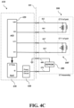
- FIG. 4 C illustrates an exemplary and non-limiting embodiment of a circuit diagram.
- FIG. 5 illustrates an exemplary and non-limiting embodiment of a distal end of a current transformer.
- FIG. 6 illustrates an exemplary and non-limiting embodiment of an exploded view of a current transformer.
- FIG. 7 illustrates an exemplary and non-limiting embodiment of a plug and cord for a current transformer assembly.
- a power monitor may be installed in a building to obtain information about power usage within the building.
- a power monitor may be installed in a conventional electrical panel, may be part of a smart electrical panel, or may be part of a smart electrical meter.
- a power monitor may determine information about power consumption by using sensors that measure an electrical property of the power mains (e.g., alternating current (AC) power line) that provide power to the building or an electrical property of power generated by solar panels.
- a power monitor may have a sensor (e.g., a current sensing device) for each of the two mains.
- the sensors of a power monitor may include a current transformer, such as any of the current transformers described herein.
- a power monitor may have any of the characteristics of power monitors as described in U.S. Pat. Nos. 9,443,195; 9,699,529; or U.S. Pat. No. 10,586,177, each of which are incorporated herein by reference in their entireties.
- Current transformer 100 includes in part a clamp formed of a semi-elliptical first housing 102 and a semi-elliptical second housing 104 .
- First housing 102 is formed of first handle portion 108 and first distal portion 110 .
- second housing 104 is formed of second handle portion 112 and second distal portion 114 .
- First distal portion 110 extends and terminates at first housing terminus 118 while second distal portion 114 extends and terminates at second housing terminus 122 , such as including a mating portion 120 to reduce misalignment.
- First housing 102 and second housing 104 rotate axially about fulcrum point 106 .
- Fulcrum point 106 defines, generally, the division between the second handle portion 112 and second distal portion 114 of second housing 104 .
- Fulcrum point 106 similarly defines, generally, the division between the first handle portion 108 and first distal portion 110 of first housing 102 .
- an internal spring situated around the fulcrum point 106 provides rotational force to each of the first housing 102 and second housing 104 so as to render the current transformer 100 in a closed state with a first housing terminus 118 in contact with a second housing terminus 122 .
- an operator of current transformer 100 may squeeze, with one hand, first handle portion 108 and second handle portion 112 towards one another resulting in a rotation of the first housing 102 and second housing 104 about fulcrum point 106 and separating first housing terminus 118 from second housing terminus 122 .
- First housing terminus 118 and second housing terminus 122 may be thus separated a distance sufficient greater than or equal to a diameter of an electrical main.
- an electrical main may be slid into the gap so formed at which point the pressure applied to first handle portion 108 and second handle portion 112 may be released. Releasing the pressure applied to first handle portion 108 and second handle portion 112 causes the current transformer 100 to return to a closed state whereby the electrical main is secured between first distal portion 110 and second distal portion 114 .
- Fulcrum point 106 divides the longitudinal extent of current transformer 100 into a proximal distance d 1 and a distal distance d 2 .
- the ratio of d 1 to d 2 may be between 1:5 and 1:8, preferably approximately 1:7.
- a ratio of 1:7 allows for a distance d 1 that is sufficiently small to allow for a user to open the current transformer 100 with one hand.
- These ratios produce a reduced end-to-end length of the current transformer 100 that allows the maximum oval area for engagement with a reduced handle size so as to fit into tight places.
- the ratio allows a smaller handle while enabling single hand installation due to low spring force and design features of the hinge.
- first and second housings 102 , 104 are formed of plastic material and have an overall thickness of approximately 11 millimeters (mm), which may be thinner than conventional current transformers. The thickness of the walls of the plastic housing may nevertheless be sufficient to meet the UL94 V-0 flame retardant rating.
- Connector 116 may provide electrical signals to and from current transformer 100 .
- connector 116 transmits a signal generated by the current transformer 100 resulting from electrical current passing through an electrical main.
- core 204 Housed within first distal portion 110 is core 204 .
- Cores 204 , 206 may be fabricated of a ferrite homogeneous material (providing low performance, lowest cost) and/or a homogeneous iron cores (providing mid performance, mid cost), or iron cores made from laminated sheets (providing highest performance, highest cost).
- a ferrite homogeneous material providing low performance, lowest cost
- a homogeneous iron cores providing mid performance, mid cost
- iron cores made from laminated sheets providing highest performance, highest cost
- silicon iron cores there are several grades of silicon iron cores that may be employed.
- silicon iron core that is laminated in sheets to create the structure having, for example, a reduced cross sectional area being approximately 3.5 mm ⁇ 7.5 mm adapted to produce a small geometry with the maximum flux saturation for best performance.
- core 206 housed within second distal portion 114 is core 206 .
- Core 204 is surrounded along a sizeable portion of its length by winding 200 .
- Core 206 is surrounded along a sizeable portion of its length by winding 202 .
- both of core 204 and winding 200 fit inside the walls of first distal portion 110 such that gaps 208 , 208 ′ exist on either side of core 204 and winding 200 between the walls forming first distal portion 110 .
- core 206 and winding 202 fit inside the walls of second distal portion 114 such that gaps 210 , 210 ′ exist on either side of core 206 and winding 202 between the walls forming second distal portion 114 .
- Pivot member 212 Extending through core 204 and winding 200 is pivot member 212 .
- Pivot member 212 is generally cylindrical in shape and is adapted such that opposing ends of pivot member 212 may by inserted into reciprocating holes or indentations 312 (as illustrated in FIG. 3 A ) fabricated into the walls of first distal portion 110 so as to allow core 204 and winding 200 to rotate about pivot member 212 as indicated within first distal portion 110 and as provided by gaps 208 , 208 ′.
- pivot member 212 may be attached to the surface of core 204 .
- one or more pivot members may be fabricated as part of the first and second distal portions with such pivot members engaging with one or more holes or indentations fabricated as part of cores 204 , 206 or in a casing enclosing cores 204 , 206 .
- Pivot member 214 Extending through core 206 and winding 202 is pivot member 214 .
- Pivot member 214 is generally cylindrical in shape and is adapted such that opposing ends of pivot member 214 may by inserted into reciprocating holes 314 (as illustrated in FIG. 3 A ) fabricated into the walls of second distal portion 114 so as to allow core 206 and winding 202 to rotate about pivot member 214 as indicated within second distal portion 114 and as provided by gaps 210 , 210 ′.
- first proximal core end 216 comes into contact with second proximal core end 220 .
- first distal core end 218 comes into contact with second distal core end 222 .
- each core 204 , 206 is adapted to rotate into a position whereby first distal core end 218 rests in contact with second distal core end 222 and first proximal core end 216 rests in contact with second proximal core end 220 .
- the contacts between the distal core ends and/or the proximal core ends may be incomplete or insufficient, and thus reducing the accuracy of the current transformer.
- An advantage of the configuration of current transformer 100 is that the amount of force applied by spring 306 to close the clamp may be reduced.
- the reduced force of spring 306 allows for easier opening of the clamp by an operator using only one hand.
- the configuration of the current transformer allows a reduced force spring to provide sufficient mating and contact between the ends of core 204 and core 206 .
- lock 124 extends from second handle portion 112 and is axially connected thereto so as to rotate about pivot point 126 .
- FIG. 1 shows the current transformer 100 in a closed position.
- lock 124 may be rotated axially about pivot point 126 to engage with first handle portion 108 so as to prevent either first handle portion 108 or second handle portion 112 from moving towards one another when squeezed by a user.
- Engaging lock 124 ensures that the two halves of the cores 204 , 206 , achieve and maintain solid contact with each other.
- Lock 124 further ensures that when a panel of a cabinet in which the current transformer 100 is housed is closed, neither the panel nor other components will force the current transformer 100 to open. As illustrated, the lock 124 closing action is in the desired direction to mechanically wedge the assembly closed.
- the lock 124 may provide a tactile and audible feedback that it is engaged.
- the lock 124 is designed to “CAM” away when the current transformer 100 is being opened, to avoid any cumbersome motion to pull it away while opening the current transformer for installation, in any direction.
- the lock is further designed to be locked with one hand and unlocked with one hand, keeping the hand from any area with a live conductor.
- current transformer 100 complies, generally, with industry standard IEC61010-2-032 directed to hand held and hand manipulated parts whereat a hand held part is defined as a part intended to be supported by one hand during normal use. More specifically, IEC61010-2-032 defines a type A current sensor as: “ . . .
- Type A current sensors designed to be applied around or removed from UNINSULATED HAZARDOUS LIVE conductors.
- Type A current sensors have defined HAND-HELD or hand-manipulated parts providing protection against electric shock from the conductor being measured, and also have protection against short-circuits between wires and busbars during clamping”.
- the lock may be constructed of any appropriate material, such as plastic.
- first hinge portion 302 is adapted to be inserted in rotational contact with second hinge portion 304 forming a hinge providing rotation of first housing 102 and second housing 104 about fulcrum point 106 .
- the concentric circle style hinge is formed by concentrically located first hinge portion 302 and second hinge portion 304 .
- the concentric style hinge provides sufficient support for rotating the first housing 102 with respect to second housing 104 despite the relatively thin nature of the housings.
- the concentric style hinge may also reduce any misalignment of first housing 102 with respect to second housing 104 across all three axes and thus improve mating and contact between the ends of core 204 and core 206 .
- first hinge portion 302 and second hinge portion 304 may be in the shape of a portion of a cylinder. An outer surface of first hinge portion 302 may be in contact with an inner surface of second hinge portion 304 . When the current transformer is opened or closed, the surfaces of first hinge portion 302 and second hinge portion 304 may rotate against one another.
- the cylindrical and concentric construction of the hinge provides a larger surface area than conventional hinges and thus provides more physical support for the hinge.
- First hinge portion 302 and second hinge portion 304 may be constructed of any appropriate material, such as plastic.
- first housing 102 and second housing 104 may have complementary features to mate with first hinge portion 302 and second hinge portion 304 . These complementary features may engage with the first hinge portion 302 and second hinge portion 304 to reduce any misalignment of first housing 102 with respect to second housing 104 across all three axes and thus improve mating and contact between the ends of core 204 and core 206 .
- the spring 306 may be concentric to the hinge and may be, for example, a torsion spring. In some embodiments, a center point of the coil of the spring 306 may be located at the fulcrum of the hinge. In some embodiments, the coil of the spring 306 may be inside both first hinge portion 302 and second hinge portion 304 and one or more legs of the spring may extend through first hinge portion 302 and/or second hinge portion 304 to provide resistance when the clamp is opened. Where the coil of spring 306 is inside hinge portion 302 and second hinge portion 304 , greater separation may be achieved between the live wires of the transformer and the metal of the spring (isolating live parts from dead metal), and the separation may provide for increased safety of the current transformer.
- FIG. 3 B illustrates an exemplary and non-limiting embodiment of an isometric view of a current transformer.
- reciprocating holes or indentations 312 are illustrated to allow core 204 and winding 200 to rotate about pivot member 212 (second pivot member hidden from view), and reciprocating holes or indentations 314 are illustrated to allow core 206 and winding 202 to rotate about pivot member 214 (second pivot member hidden from view).
- FIG. 4 A there is illustrated an exemplary and non-limiting embodiment of a circuit diagram of a current transformer assembly including two current transformers 100 , 100 ′ that is connected to a current transformer interface 410 through a connection interface 460 (e.g., a multi-wire cable with plug for connecting to the current transformer interface).
- the current transformer interface 410 may be used to interface with the current transformer assembly to obtain sensor readings (e.g., by a power monitoring device) or to configure the current transformer assembly, as described in greater detail below.
- the current transformer interface 410 may be integrated into or represent the power monitor as described, where the terms “current transformer interface” and “power monitor” may be used interchangeably herein.
- a memory chip 400 is attached to existing negative wires 464 464 ′ of each current transformer 100 , 100 ′, and thus, in some embodiments, may not require any additional wires (e.g., as provided through the connector interface 460 ) to accommodate connection to the memory chip 400 .
- Memory chip 400 may use any appropriate techniques for storing data, such as a volatile memory chip, a non-volatile memory chip, an EEPROM (electrically erasable programmable read-only memory), or EPROM (erasable programmable read-only memory).
- positive wires 462 462 ′ may be utilized instead of negative wires 464 464 ′ or both negative and positive wires may be utilized (e.g., negative wire 464 ′ and positive wire 462 ′.
- the memory chip 400 may be connected to the two wires of a current transformer 100 , one wire of the current transformer 100 and one wire of the current transformer 100 ′, or two wires of a current transformer 100 ′.
- different current transformers may differ one from another in their sensitivity. As a result, two different current transformers 100 making a reading of the same electrical main may differ slightly.
- a scale factor is computed for each of the two current transformers 100 , 100 ′ and stored on the memory chip 400 .
- the power monitor may obtain the scale factors for the current transformers from memory chip 400 , and use the scale factors to obtain more accurate readings from the current transformers. For example, a true current being measured may be 8 amps.
- a first current transformer may indicate a current value of 10 amps.
- the scale factor stored on memory chip 400 for the first current transformer may allow the power monitor to correct the signal received from the first current transformer to determine that the current is actually 8 amps.
- the scale factor may indicate to adjust the signal or a value received from the first current transformer downwards by a factor of 0.2 or 20%.
- the power monitor may then compute an adjusted value using the scale factor and use the adjusted value for determining information about energy consumption for one or more electrical power consuming devices in a building (such as any of the information described in the incorporated patents and applications).
- each new current transformer 100 , 100 ′ may be read and utilized such that input gathered from the newly swapped current transformers 100 , 100 ′ do not differ in scale from the previously used current transformers.
- the power monitor may read the scale factors from memory chip 400 during a startup or initialization process. In some embodiments, the power monitor may read the scale factors when instructed to do so (e.g., from a server computer in communication with the power monitor) or on a periodic basis.
- the memory chip may be connected to the existing wires (e.g., negative wires) of the current transformer assembly. Similar chips used in Mac power cords use additional wires or contact points while the present embodiment reuses existing wires and connector pins, thus reducing the connector size without interfering with the operation of the current transformer.
- the memory chip 400 may store identifying information related to each current transformer in the form of a current transformer identifier (CTID).
- CTID current transformer identifier
- This identifier may indicate, for example, a date code, date of manufacture, or a location of manufacture.
- the ability to store and retrieve information indicative of a unique current transformer 100 decreases repair costs, increases accuracy, and makes installation easier. In addition, installation is easier as there is no need to match a current transformer to a unit jack. Further, product support is reduced as mis-installed current transformers may result in support calls about inaccuracy. Repair costs are further reduced as there is no need to replace a power monitor and current transformers as a unit—just the failing component.
- current transformer interface 410 may be used to obtain sensor readings from the current transformer, read the scale factors from memory chip 400 , or write the scale factors to memory chip 400 .
- a power monitor may include current transformer interface 410 or a calibration device may include current transformer interface 410 .
- Current transformer interface 410 may include analog-to-digital converter (A/D) 420 .
- A/D 420 may receive analog signals from the current transformers and produce a sequence of digital values (current transformer data or CT data) for further processing.
- Current transformer interface 410 may include system on a chip (SoC) 430 that may receive the CT data from A/D 420 . SoC 430 may further coordinate in receiving sensor data from the current transformers and reading or writing scale factors from memory chip 400 . SoC 430 may include an enable pin or output that switches the current transformer interface 410 between reading sensor data and reading or writing scale factors.
- the enable output may be connected to a multiplexor circuit, such as multiplexors 450 , 450 ′. For example, where the enable output is 0, the multiplexors may be configured to send sensor data to A/D 420 , and where the enable output is 1, the multiplexors may be configured to assist with reading from or writing to memory chip 400 .
- Current transformer interface 410 may include power and interface (I/F) circuit 440 to assist with reading from or writing to memory chip 400 .
- I/F circuit 440 may provide the power needed to perform a read or write operation and an interface to convert the scale factors stored on memory chip 400 into a format to be used by SoC 430 .
- FIG. 4 B there is illustrated an exemplary and non-limiting embodiment of a circuit diagram of a current transformer assembly illustrating a first connection to the memory chip 400 attached to an existing negative wire 464 ′ of the current transformer 100 ′ and a second connection 470 to the memory chip 400 to the power and I/F circuit 440 .
- a positive wire may be utilized instead of negative wire for the first connection.
- the current transformer interface 410 may be used to interface with the current transformer assembly 100 ′ to obtain sensor readings or to configure the current transformer assembly through a first connection 462 ′ and second connection 464 ′, and the memory chip 400 is attached to the power and I/F circuit 440 by one of the first or second connections (e.g., negative wire connection 464 ′, or in embodiments any of the wired connections to the current transformers 100 100 ′) and by a third wire 470 .
- the memory chip 400 would share one of the existing wire connections to the current transformers 100 100 ′ and utilize an additional wired connection 470 to accommodate connectivity with the memory chip 400 .
- the wired connections through the connection interface 460 to the current transformer 100 ′ and the memory chip 400 may include three wires (e.g., in addition to the two wires for the current transformer 100 ).
- FIG. 4 C there is illustrated an exemplary and non-limiting embodiment of a circuit diagram of a current transformer assembly illustrating a first connection to the memory chip 400 attached to the power and I/F circuit 440 and a second connection to the memory chip 400 attached to a common connection point of the current transformer interface 410 .
- the current transformer interface 410 may be used to interface with the current transformer assembly 100 ′ to obtain sensor readings or to configure the current transformer assembly through a first wire connection 462 ′ and second wire connection 464 ′, and the memory chip 400 is attached to the power and I/F circuit 440 by dedicated third connection wire 470 and fourth connection wire 480 .
- connections to the memory chip 400 may be independent of connections to the current transformers 100 100 ′.
- the wired connections through the connection interface 460 to the current transformer 100 ′ and the memory chip 400 may include four wires (e.g., in addition to the two wires for the current transformer 100 ).
- distal end 500 , 502 are in contact with each other when the current transformer 100 in a closed position.
- distal end 502 is tapered or dimpled with respect to opposing distal end 500 .
- This reduced nose area of distal end 502 allows for a reduced height in this region to provide for increased manipulation and orientation in consumer electrical panels.
- the current transformer windings may be kept away from this region allowing the plastic shell to be reduced and create this advantageous shape.
- the interlocking nose pieces provide a shield to prevent exposing this inner core and their windings.
- the tapering accommodates a known barrier/obstruction commonly present in electrical panels and/or solar junction panels.
- first hinge portion 602 is adapted to be inserted in rotational contact with second hinge portion 604 forming a hinge providing rotation of first housing 102 and second housing 104 about fulcrum point 106 .
- the concentric circle style hinge is formed by concentrically located first hinge portion 602 and second hinge portion 604 .
- the coil of spring 606 may be outside both first hinge portion 602 and second hinge portion 604 .
- Plug 702 may be adapted to be plugged into a power monitor.
- First connection 704 may be connected to a first current transformer 100 (not shown) through wires 462 , 464
- second connection 704 ′ may be connected to a second current transformer 100 ′ (not shown) through wires 462 ′, 464 ′.
- a current transformer assembly may have a single current transformer (and thus a single cord and connection, e.g., 462 , 464 ), and in some embodiments, a current transformer assembly may have more than two current transformers (and thus more than two cords and connections 462 , 464 , 462 ′, 464 ′).
- a current transformer assembly includes memory chip 400
- memory chip 400 may be situated in any appropriate location. In some embodiments, memory chip 400 may be situated within the plug 702 .
- the memory chip 400 may connect to some combination of the existing connections 462 , 464 , 462 ′, 464 ′ of the current transformers 100 , 100 ′, to one of the existing connections 462 , 464 , 462 ′, 464 ′ of the current transformers 100 , 100 ′ and an additional dedicated connection 470 (additional wire not shown), or to dedicated connections 470 , 480 (additional wires not shown).
- the methods and systems described herein may be deployed in part or in whole through a machine that executes computer software, program codes, and/or instructions on a processor.
- the present disclosure may be implemented as a method on the machine, as a system or apparatus as part of or in relation to the machine, or as a computer program product embodied in a computer readable medium executing on one or more of the machines.
- the processor may be part of a server, cloud server, client, network infrastructure, mobile computing platform, stationary computing platform, or other computing platform.
- a processor may be any kind of computational or processing device capable of executing program instructions, codes, binary instructions and the like.
- the processor may be or may include a signal processor, digital processor, embedded processor, microprocessor or any variant such as a co-processor (math co-processor, graphic co-processor, communication co-processor and the like) and the like that may directly or indirectly facilitate execution of program code or program instructions stored thereon.
- the processor may enable execution of multiple programs, threads, and codes. The threads may be executed simultaneously to enhance the performance of the processor and to facilitate simultaneous operations of the application.
- methods, program codes, program instructions and the like described herein may be implemented in one or more thread.
- the thread may spawn other threads that may have assigned priorities associated with them; the processor may execute these threads based on priority or any other order based on instructions provided in the program code.
- the processor may include non-transitory memory that stores methods, codes, instructions and programs as described herein and elsewhere.
- the processor may access a non-transitory storage medium through an interface that may store methods, codes, and instructions as described herein and elsewhere.
- the storage medium associated with the processor for storing methods, programs, codes, program instructions or other type of instructions capable of being executed by the computing or processing device may include but may not be limited to one or more of a CD-ROM, DVD, memory, hard disk, flash drive, RAM, ROM, cache and the like.
- a processor may include one or more cores that may enhance speed and performance of a multiprocessor.
- the process may be a dual core processor, quad core processors, other chip-level multiprocessor and the like that combine two or more independent cores to provide speed improvements.
- the methods and systems described herein may be deployed in part or in whole through a machine that executes computer software on a server, client, firewall, gateway, hub, router, or other such computer and/or networking hardware.
- the software program may be associated with a server that may include a file server, print server, domain server, internet server, intranet server, cloud server, and other variants such as secondary server, host server, distributed server and the like.
- the server may include one or more of memories, processors, computer readable media, storage media, ports (physical and virtual), communication devices, and interfaces capable of accessing other servers, clients, machines, and devices through a wired or a wireless medium, and the like.
- the methods, programs, or codes as described herein and elsewhere may be executed by the server.
- other devices required for execution of methods as described in this application may be considered as a part of the infrastructure associated with the server.
- the server may provide an interface to other devices including, without limitation, clients, other servers, printers, database servers, print servers, file servers, communication servers, distributed servers, social networks, and the like. Additionally, this coupling and/or connection may facilitate remote execution of program across the network. The networking of some or all of these devices may facilitate parallel processing of a program or method at one or more location without deviating from the scope of the disclosure.
- any of the devices attached to the server through an interface may include at least one storage medium capable of storing methods, programs, code and/or instructions.
- a central repository may provide program instructions to be executed on different devices.
- the remote repository may act as a storage medium for program code, instructions, and programs.
- the software program may be associated with a client that may include a file client, print client, domain client, internet client, intranet client and other variants such as secondary client, host client, distributed client and the like.
- the client may include one or more of memories, processors, computer readable media, storage media, ports (physical and virtual), communication devices, and interfaces capable of accessing other clients, servers, machines, and devices through a wired or a wireless medium, and the like.
- the methods, programs, or codes as described herein and elsewhere may be executed by the client.
- other devices required for execution of methods as described in this application may be considered as a part of the infrastructure associated with the client.
- the client may provide an interface to other devices including, without limitation, servers, other clients, printers, database servers, print servers, file servers, communication servers, distributed servers and the like. Additionally, this coupling and/or connection may facilitate remote execution of program across the network. The networking of some or all of these devices may facilitate parallel processing of a program or method at one or more location without deviating from the scope of the disclosure.
- any of the devices attached to the client through an interface may include at least one storage medium capable of storing methods, programs, applications, code and/or instructions.
- a central repository may provide program instructions to be executed on different devices.
- the remote repository may act as a storage medium for program code, instructions, and programs.
- the methods and systems described herein may be deployed in part or in whole through network infrastructures.
- the network infrastructure may include elements such as computing devices, servers, routers, hubs, firewalls, clients, personal computers, communication devices, routing devices and other active and passive devices, modules and/or components as known in the art.
- the computing and/or non-computing device(s) associated with the network infrastructure may include, apart from other components, a storage medium such as flash memory, buffer, stack, RAM, ROM and the like.
- the processes, methods, program codes, instructions described herein and elsewhere may be executed by one or more of the network infrastructural elements.
- SaaS software as a service
- PaaS platform as a service
- IaaS infrastructure as a service
- the methods, program codes, and instructions described herein and elsewhere may be implemented on a cellular network has sender-controlled contact media content item multiple cells.
- the cellular network may either be frequency division multiple access (FDMA) network or code division multiple access (CDMA) network.
- FDMA frequency division multiple access
- CDMA code division multiple access
- the cellular network may include mobile devices, cell sites, base stations, repeaters, antennas, towers, and the like.
- the cell network may be a GSM, GPRS, 3G, EVDO, mesh, or other networks types.
- the mobile devices may include navigation devices, cell phones, mobile phones, mobile personal digital assistants, laptops, palmtops, netbooks, pagers, electronic books readers, music players and the like. These devices may include, apart from other components, a storage medium such as a flash memory, buffer, RAM, ROM and one or more computing devices.
- the computing devices associated with mobile devices may be enabled to execute program codes, methods, and instructions stored thereon. Alternatively, the mobile devices may be configured to execute instructions in collaboration with other devices.
- the mobile devices may communicate with base stations interfaced with servers and configured to execute program codes.
- the mobile devices may communicate on a peer-to-peer network, mesh network, or other communications network.
- the program code may be stored on the storage medium associated with the server and executed by a computing device embedded within the server.
- the base station may include a computing device and a storage medium.
- the storage device may store program codes and instructions executed by the computing devices associated with the base station.
- the computer software, program codes, and/or instructions may be stored and/or accessed on machine readable media that may include: computer components, devices, and recording media that retain digital data used for computing for some interval of time; semiconductor storage known as random access memory (RAM); mass storage typically for more permanent storage, such as optical discs, forms of magnetic storage like hard disks, tapes, drums, cards and other types; processor registers, cache memory, volatile memory, non-volatile memory; optical storage such as CD, DVD; removable media such as flash memory (e.g.
- RAM random access memory
- mass storage typically for more permanent storage, such as optical discs, forms of magnetic storage like hard disks, tapes, drums, cards and other types
- processor registers cache memory, volatile memory, non-volatile memory
- optical storage such as CD, DVD
- removable media such as flash memory (e.g.
- USB sticks or keys floppy disks, magnetic tape, paper tape, punch cards, standalone RAM disks, Zip drives, removable mass storage, off-line, and the like; other computer memory such as dynamic memory, static memory, read/write storage, mutable storage, read only, random access, sequential access, location addressable, file addressable, content addressable, network attached storage, storage area network, bar codes, magnetic ink, and the like.
- the methods and systems described herein may transform physical and/or or intangible items from one state to another.
- the methods and systems described herein may also transform data representing physical and/or intangible items from one state to another.
- machines may include, but may not be limited to, personal digital assistants, laptops, personal computers, mobile phones, other handheld computing devices, medical equipment, wired or wireless communication devices, transducers, chips, calculators, satellites, tablet PCs, electronic books, gadgets, electronic devices, devices has sender-controlled contact media content item artificial intelligence, computing devices, networking equipment, servers, routers and the like.
- the elements depicted in the flow chart and block diagrams or any other logical component may be implemented on a machine capable of executing program instructions.
- the methods and/or processes described above, and steps associated therewith, may be realized in hardware, software or any combination of hardware and software suitable for a particular application.
- the hardware may include a general-purpose computer and/or dedicated computing device or specific computing device or particular aspect or component of a specific computing device.
- the processes may be realized in one or more microprocessors, microcontrollers, embedded microcontrollers, programmable digital signal processors or other programmable device, along with internal and/or external memory.
- the processes may also, or instead, be embodied in an application specific integrated circuit, a programmable gate array, programmable array logic, or any other device or combination of devices that may be configured to process electronic signals. It will further be appreciated that one or more of the processes may be realized as a computer executable code capable of being executed on a machine-readable medium.
- the computer executable code may be created using a structured programming language such as C, an object oriented programming language such as C++, or any other high-level or low-level programming language (including assembly languages, hardware description languages, and database programming languages and technologies) that may be stored, compiled or interpreted to run on one of the above devices, as well as heterogeneous combinations of processors, processor architectures, or combinations of different hardware and software, or any other machine capable of executing program instructions.
- a structured programming language such as C
- an object oriented programming language such as C++
- any other high-level or low-level programming language including assembly languages, hardware description languages, and database programming languages and technologies
- methods described above and combinations thereof may be embodied in computer executable code that, when executing on one or more computing devices, performs the steps thereof.
- the methods may be embodied in systems that perform the steps thereof, and may be distributed across devices in a number of ways, or all of the functionality may be integrated into a dedicated, standalone device or other hardware.
- the means for performing the steps associated with the processes described above may include any of the hardware and/or software described above. All such permutations and combinations are intended to fall within the scope of the present disclosure.
Landscapes
- Engineering & Computer Science (AREA)
- Power Engineering (AREA)
- Microelectronics & Electronic Packaging (AREA)
- Physics & Mathematics (AREA)
- General Physics & Mathematics (AREA)
- Multimedia (AREA)
- Measuring Instrument Details And Bridges, And Automatic Balancing Devices (AREA)
- Transformers For Measuring Instruments (AREA)
Abstract
Description
Claims (24)
Priority Applications (2)
| Application Number | Priority Date | Filing Date | Title |
|---|---|---|---|
| US17/990,549 US12055566B2 (en) | 2019-07-11 | 2022-11-18 | Locking current transformer |
| US18/786,809 US20240385224A1 (en) | 2019-07-11 | 2024-07-29 | Locking current transformer |
Applications Claiming Priority (3)
| Application Number | Priority Date | Filing Date | Title |
|---|---|---|---|
| US201962873132P | 2019-07-11 | 2019-07-11 | |
| US16/858,897 US11536747B2 (en) | 2019-07-11 | 2020-04-27 | Current transformer with self-adjusting cores |
| US17/990,549 US12055566B2 (en) | 2019-07-11 | 2022-11-18 | Locking current transformer |
Related Parent Applications (1)
| Application Number | Title | Priority Date | Filing Date |
|---|---|---|---|
| US16/858,897 Continuation US11536747B2 (en) | 2019-07-11 | 2020-04-27 | Current transformer with self-adjusting cores |
Related Child Applications (1)
| Application Number | Title | Priority Date | Filing Date |
|---|---|---|---|
| US18/786,809 Continuation US20240385224A1 (en) | 2019-07-11 | 2024-07-29 | Locking current transformer |
Publications (2)
| Publication Number | Publication Date |
|---|---|
| US20230081587A1 US20230081587A1 (en) | 2023-03-16 |
| US12055566B2 true US12055566B2 (en) | 2024-08-06 |
Family
ID=74102269
Family Applications (5)
| Application Number | Title | Priority Date | Filing Date |
|---|---|---|---|
| US16/858,905 Active 2041-03-30 US11768228B2 (en) | 2019-07-11 | 2020-04-27 | Current transformer with calibration information |
| US16/858,897 Active 2040-09-02 US11536747B2 (en) | 2019-07-11 | 2020-04-27 | Current transformer with self-adjusting cores |
| US17/990,549 Active US12055566B2 (en) | 2019-07-11 | 2022-11-18 | Locking current transformer |
| US18/449,469 Active US12385951B2 (en) | 2019-07-11 | 2023-08-14 | Current transformer with calibration information |
| US18/786,809 Pending US20240385224A1 (en) | 2019-07-11 | 2024-07-29 | Locking current transformer |
Family Applications Before (2)
| Application Number | Title | Priority Date | Filing Date |
|---|---|---|---|
| US16/858,905 Active 2041-03-30 US11768228B2 (en) | 2019-07-11 | 2020-04-27 | Current transformer with calibration information |
| US16/858,897 Active 2040-09-02 US11536747B2 (en) | 2019-07-11 | 2020-04-27 | Current transformer with self-adjusting cores |
Family Applications After (2)
| Application Number | Title | Priority Date | Filing Date |
|---|---|---|---|
| US18/449,469 Active US12385951B2 (en) | 2019-07-11 | 2023-08-14 | Current transformer with calibration information |
| US18/786,809 Pending US20240385224A1 (en) | 2019-07-11 | 2024-07-29 | Locking current transformer |
Country Status (1)
| Country | Link |
|---|---|
| US (5) | US11768228B2 (en) |
Families Citing this family (8)
| Publication number | Priority date | Publication date | Assignee | Title |
|---|---|---|---|---|
| US10750252B2 (en) | 2017-02-22 | 2020-08-18 | Sense Labs, Inc. | Identifying device state changes using power data and network data |
| US10740691B2 (en) | 2018-10-02 | 2020-08-11 | Sense Labs, Inc. | Identifying devices connected to a smart plug |
| US11768228B2 (en) | 2019-07-11 | 2023-09-26 | Sense Labs, Inc. | Current transformer with calibration information |
| USD944731S1 (en) * | 2019-07-11 | 2022-03-01 | Sense Labs, Inc. | Electrical current sensor |
| USD995387S1 (en) * | 2020-08-04 | 2023-08-15 | Yetong Enterprise Co., Ltd. | Dual field coil eddy current brake |
| CN113053646B (en) * | 2021-04-06 | 2025-08-15 | 江阴市星火电子科技有限公司 | Compact outdoor open-close type current transformer |
| EP4124869B1 (en) * | 2021-07-31 | 2023-10-11 | LEM International SA | Current transducer |
| FR3137177B1 (en) * | 2022-06-23 | 2024-06-21 | Chauvin Arnoux | Clamp meter for AC and DC leakage currents |
Citations (150)
| Publication number | Priority date | Publication date | Assignee | Title |
|---|---|---|---|---|
| US3263021A (en) | 1964-05-21 | 1966-07-26 | Metalastik Ltd | Cable spacers for multi-conductor electrical overhead transmission lines |
| US3611136A (en) * | 1969-09-29 | 1971-10-05 | Tomosuke Ito | Spring-operated field strength measuring device in an electromagnetic-type amperemeter |
| USD248851S (en) | 1976-07-29 | 1978-08-08 | Howard Langlie | Corner insulator for electric fences |
| US4316142A (en) | 1979-11-20 | 1982-02-16 | Kyoritsu Electrical Instruments Works, Ltd. | Clamp type ammeter |
| USD274614S (en) | 1982-02-26 | 1984-07-10 | Esterline Angus Instrument Corp. | Current transformer |
| USD313791S (en) | 1987-01-20 | 1991-01-15 | Kitagawa Industries Co., Ltd. | Absorber of electric noise |
| FR2673727A1 (en) * | 1991-03-04 | 1992-09-11 | Marechaux Dubost Instr | Clip-on ammeter with improved actuating device |
| US5162772A (en) | 1990-03-01 | 1992-11-10 | Ferrishield, Inc. | Ferrite suppressor case with internal locking system |
| US5652507A (en) * | 1996-01-31 | 1997-07-29 | Eaton Corporation | Apparatus and method for measuring an AC current which saturates the core of a current transformer |
| US5945993A (en) | 1998-01-30 | 1999-08-31 | Hewlett-Packard Company | Pictograph-based method and apparatus for controlling a plurality of lighting loads |
| US6311105B1 (en) | 1998-05-29 | 2001-10-30 | Powerweb, Inc. | Multi-utility energy control system |
| US6456060B1 (en) * | 2000-08-29 | 2002-09-24 | Actuant Corporation | Multi-meter with locking clamp |
| US20020178047A1 (en) | 2000-09-15 | 2002-11-28 | Or Ellen Pak-Wah | Energy management system and method for monitoring and optimizing energy usage, identifying energy savings and facilitating procurement of energy savings products and services |
| US20030216971A1 (en) | 1999-07-15 | 2003-11-20 | Logical Energy Solutions, Llc | User interface for a system using digital processors and networks to facilitate, analyze and manage resource consumption |
| US20040142662A1 (en) | 2003-01-21 | 2004-07-22 | Thomas Ehrenberg | Remote change of status signal device |
| US20040255171A1 (en) | 2003-06-13 | 2004-12-16 | Zimmer Vincent J. | Power management for clustered computing platforms |
| US20050034023A1 (en) | 2002-12-16 | 2005-02-10 | Maturana Francisco P. | Energy management system |
| US20050085973A1 (en) | 2003-08-26 | 2005-04-21 | Ken Furem | System and method for remotely analyzing machine performance |
| US20050108582A1 (en) | 2000-09-27 | 2005-05-19 | Fung Henry T. | System, architecture, and method for logical server and other network devices in a dynamically configurable multi-server network environment |
| US20060155514A1 (en) | 2004-12-16 | 2006-07-13 | Caroline Drouart | Method of tracking the performance of an industrial appliance |
| US7085814B1 (en) | 1999-06-11 | 2006-08-01 | Microsoft Corporation | Data driven remote device control model with general programming interface-to-network messaging adapter |
| US20060235574A1 (en) | 2005-04-19 | 2006-10-19 | Genscape, Inc. | Method and system for AC power grid monitoring |
| USD534120S1 (en) | 2005-01-19 | 2006-12-26 | Power Measurement Ltd. | Current transformer body |
| USD550619S1 (en) | 2006-11-02 | 2007-09-11 | Power Measurement Ltd. | Current transformer body |
| CN101083586A (en) | 2006-05-31 | 2007-12-05 | Sap股份公司 | Modular monitor service for smart item monitoring |
| US7353182B1 (en) | 2000-06-30 | 2008-04-01 | Accenture Llp | System and method for providing a multi-channel customer interaction center |
| CN101241367A (en) | 2008-03-03 | 2008-08-13 | 当代天启技术(北京)有限公司 | Architecture automatized control system and method |
| US20080306985A1 (en) | 2007-06-11 | 2008-12-11 | Lucid Design Group, Llc | Collecting, sharing, comparing, and displaying resource usage data |
| US20090058399A1 (en) * | 2007-08-30 | 2009-03-05 | Fluke Corporation | Clamp jaw assembly |
| US20090222360A1 (en) | 2008-02-28 | 2009-09-03 | Bernd Schmitt | Managing consistent interfaces for business objects across heterogeneous systems |
| USD610541S1 (en) | 2009-03-25 | 2010-02-23 | Phoenix Contact Gmbh & Co. Kg | Current transducer |
| US20100211222A1 (en) | 2009-02-19 | 2010-08-19 | Michel Ghosn | Method and apparatus for comprehensive energy measurement and analysis of a building |
| US20100217550A1 (en) | 2009-02-26 | 2010-08-26 | Jason Crabtree | System and method for electric grid utilization and optimization |
| JP2010213411A (en) | 2009-03-09 | 2010-09-24 | A-One Meditec Co Ltd | Power management system |
| KR20100111170A (en) | 2009-04-06 | 2010-10-14 | 주식회사 바른기술 | Power saving system and method using ethernet network based multi-outlet |
| US20100332373A1 (en) | 2009-02-26 | 2010-12-30 | Jason Crabtree | System and method for participation in energy-related markets |
| WO2011002735A1 (en) | 2009-07-01 | 2011-01-06 | Carnegie Mellon University | Methods and apparatuses for monitoring energy consumption and related operations |
| WO2011029137A2 (en) | 2009-09-09 | 2011-03-17 | La Trobe University | Method and system for energy management |
| US20110066300A1 (en) | 2009-09-11 | 2011-03-17 | General Electric Company | Method and system for demand response in a distribution network |
| CN102098323A (en) | 2009-12-01 | 2011-06-15 | 法国电信公司 | Status prompt method and system |
| US20110196547A1 (en) | 2010-02-09 | 2011-08-11 | Jong Soo Park | Apparatus for controlling a power using a smart device and method thereof |
| US20110245987A1 (en) | 2010-04-06 | 2011-10-06 | Battelle Memorial Institute | Grid regulation services for energy storage devices based on grid frequency |
| CA2802915A1 (en) | 2010-06-17 | 2011-12-22 | Awesense Wireless Inc. | Method, sensor apparatus and system for determining losses in an electrical power grid |
| CN102314547A (en) | 2010-06-08 | 2012-01-11 | 霍尼韦尔国际公司 | The system and method that is used for virtual submeter |
| JP2012016270A (en) | 2010-07-02 | 2012-01-19 | Jiaotong Univ | Electric power monitoring device and method of identifying state of electric appliance |
| US20120022713A1 (en) | 2010-01-14 | 2012-01-26 | Deaver Sr Brian J | Power Flow Simulation System, Method and Device |
| US20120065802A1 (en) | 2010-09-14 | 2012-03-15 | Joulex, Inc. | System and methods for automatic power management of remote electronic devices using a mobile device |
| US20120092060A1 (en) | 2010-10-15 | 2012-04-19 | Echola Systems, Llc. | Reliable low-cost hybrid switch module for switched power distribution systems |
| CN102549521A (en) | 2009-10-07 | 2012-07-04 | 住友电气工业株式会社 | Power management system, power management device, network management device, information processing device, program, power management method, and information processing method |
| US20120181869A1 (en) | 2007-03-14 | 2012-07-19 | Steve Chapel | Parallel redundant power distribution |
| US20120197448A1 (en) | 2011-02-01 | 2012-08-02 | Samsung Electronics Co., Ltd. | Electric device, power management apparatus and method for controlling the same |
| US20120197560A1 (en) | 2011-01-28 | 2012-08-02 | Hampden Kuhns | Signal identification methods and systems |
| US8239073B2 (en) | 2008-04-17 | 2012-08-07 | Asoka Usa Corporation | Systems and methods for controlling energy consumption |
| WO2012106709A2 (en) | 2011-02-04 | 2012-08-09 | Myenersave, Inc. | Systems and methods for improving the accuracy of appliance level disaggregation in non-intrusive appliance load monitoring techniques |
| US20120221718A1 (en) | 2009-08-21 | 2012-08-30 | Imes Kevin R | Energy management method |
| US20120239773A1 (en) | 2011-03-14 | 2012-09-20 | David Tayvel Blustein | Modular Intelligent Power System |
| US20120278272A1 (en) | 2011-04-27 | 2012-11-01 | Hyungsul Kim | System and method for disaggregating power load |
| US20120280833A1 (en) | 2011-05-06 | 2012-11-08 | Greenwave Reality, Pte Ltd. | Smart Meter Emulation |
| US20120290239A1 (en) | 2011-05-11 | 2012-11-15 | Industrial Technology Research Institute | Thin metal film measurement method |
| CN102822639A (en) | 2010-01-25 | 2012-12-12 | 吉尼瓦洁净技术公司 | Automatic detection of appliances |
| US20120319675A1 (en) | 2011-06-14 | 2012-12-20 | International Business Machines Corporation | Calibration of non-contact voltage sensors |
| US20130033267A1 (en) * | 2009-10-28 | 2013-02-07 | Joseph Yossi Harlev | Optical sensor assembly for installation on a current carrying cable |
| WO2013022035A1 (en) | 2011-08-08 | 2013-02-14 | 日東電工株式会社 | Smart tap |
| US20130066479A1 (en) | 2011-09-14 | 2013-03-14 | Honeywell International Inc. | Energy consumption disaggregation system |
| US20130076343A1 (en) | 2011-02-09 | 2013-03-28 | International Business Machines Corporation | Non-contact current and voltage sensing clamp |
| US20130132009A1 (en) | 2010-08-06 | 2013-05-23 | Jerome Rolia | Systems and methods for apportioning power consumption |
| US20130183043A1 (en) | 2012-01-13 | 2013-07-18 | David Elberbaum | Apparatus for employing low ohmic alloy conductors and method for simplifying current drain data retrieval |
| WO2013106923A1 (en) | 2012-01-20 | 2013-07-25 | Energy Aware Technology Inc. | System and method of compiling and organizing power consumption data and converting such data into one or more user actionable formats |
| US20130241746A1 (en) | 2011-08-15 | 2013-09-19 | Digimarc Corporation | A/b/c phase determination and synchrophasor measurement using common electric smart meters and wireless communications |
| US20130262197A1 (en) | 2012-04-02 | 2013-10-03 | Accenture Global Services Limited | Community energy management system |
| US20130268357A1 (en) | 2011-09-15 | 2013-10-10 | Stephan HEATH | Methods and/or systems for an online and/or mobile privacy and/or security encryption technologies used in cloud computing with the combination of data mining and/or encryption of user's personal data and/or location data for marketing of internet posted promotions, social messaging or offers using multiple devices, browsers, operating systems, networks, fiber optic communications, multichannel platforms |
| WO2013179671A1 (en) | 2012-06-01 | 2013-12-05 | パナソニック株式会社 | Equipment monitoring device, equipment monitoring system, registration terminal and equipment monitoring method |
| US20140052304A1 (en) | 2012-08-16 | 2014-02-20 | Infosys Limited | Dynamic enforcement of power management policy and methods thereof |
| US8674823B1 (en) | 2009-05-12 | 2014-03-18 | Plug ID, LLC. | Power management system |
| JP2014072561A (en) | 2012-09-27 | 2014-04-21 | Nitto Denko Corp | Home electric appliance remote monitoring system |
| JP2014086995A (en) | 2012-10-26 | 2014-05-12 | Mitsubishi Electric Corp | Frequency detection circuit |
| US8760151B2 (en) | 2010-08-10 | 2014-06-24 | Cooper Technologies Company | Ajustable overhead conductor monitoring device |
| US20140188565A1 (en) | 2012-12-27 | 2014-07-03 | International Business Machines Corporation | Customer demographic data change detection based on monitored utility consumption |
| US20140192677A1 (en) | 2012-06-29 | 2014-07-10 | Yen Hsiang Chew | Network routing protocol power saving method for network elements |
| US20140207255A1 (en) | 2013-01-24 | 2014-07-24 | Honeywell International, Inc. | Apparatus and method for determining an aggregate control connection status of a field device in a process control system |
| US20140214729A1 (en) | 2013-01-29 | 2014-07-31 | Industrial Technology Research Institute | Management system, smart meter, server, operation method and management method |
| US20140266784A1 (en) | 2013-03-15 | 2014-09-18 | Liebert Corporation | Mesh network synchronous power monitoring systems and methods |
| US20140278241A1 (en) | 2013-03-15 | 2014-09-18 | General Electric Company | Performance monitoring and analysis for power plants |
| KR101448683B1 (en) | 2013-08-12 | 2014-10-08 | 주식회사 인코어드 테크놀로지스 | Apparatus and system for providing an information of energy |
| US20140303796A1 (en) | 2013-04-05 | 2014-10-09 | Electronics And Telecommunications Research Institute | Apparatus and method for controlling building energy |
| US8913629B2 (en) | 2008-06-16 | 2014-12-16 | Qualcomm Atheros, Inc. | Managing coexistence on a shared power line medium |
| US8930152B2 (en) | 2009-09-25 | 2015-01-06 | University Of Washington | Whole structure contactless power consumption sensing |
| JP2015060453A (en) | 2013-09-19 | 2015-03-30 | 株式会社東芝 | Information processor and method thereof |
| US20150094968A1 (en) | 2009-02-26 | 2015-04-02 | Distributed Energy Management Inc. | Comfort-driven optimization of electric grid utilization |
| US20150102800A1 (en) | 2012-04-12 | 2015-04-16 | Schneider Electric It Corporation | System and method for detecting branch circuit current |
| US20150112906A1 (en) | 2013-10-22 | 2015-04-23 | Sandia Corporation | Methods, systems and computer program products for determining systems re-tasking |
| US20150127185A1 (en) | 2013-11-07 | 2015-05-07 | Panasonic Intellectual Property Management Co., Ltd. | Power supply-demand control method and power supply-demand control apparatus |
| US20150142695A1 (en) | 2013-11-18 | 2015-05-21 | Ye He | Energy Disaggregation Techniques for Whole-House Energy Consumption Data |
| US20150149128A1 (en) | 2013-11-22 | 2015-05-28 | General Electric Company | Systems and methods for analyzing model parameters of electrical power systems using trajectory sensitivities |
| US20150161020A1 (en) | 2013-12-08 | 2015-06-11 | Google Inc. | Methods and systems for generating virtual smart-meter data |
| US9057746B1 (en) | 2014-11-26 | 2015-06-16 | Sense Labs, Inc. | Determining information about devices in a building using different sets of features |
| US20150204558A1 (en) | 2014-01-20 | 2015-07-23 | Emerson Electric Co. | Selectively Connecting a Climate Control System Controller With More Than One Destination Server |
| JP2015136254A (en) | 2014-01-17 | 2015-07-27 | 株式会社リコー | Power supply device and device discrimination method |
| US20150244121A1 (en) | 2013-08-21 | 2015-08-27 | N2 Global Solutions Incorporated | System and apparatus for providing and managing electricity |
| CN104885406A (en) | 2012-12-18 | 2015-09-02 | 三星电子株式会社 | Method and device for remotely controlling home devices in a home network system |
| CN104897978A (en) | 2014-03-05 | 2015-09-09 | 汤姆逊许可公司 | Electrical activity sensor device for detecting electrical activity and electrical activity monitoring apparatus |
| US20150261944A1 (en) | 2014-03-17 | 2015-09-17 | Sensory, Incorporated | Unobtrusive verification of user identity |
| US20150271575A1 (en) | 2014-03-24 | 2015-09-24 | Sumitomo Electric Industries, Ltd. | Monitoring system for photovoltaic power generation and communication method therefor |
| US20150271557A1 (en) | 2014-03-24 | 2015-09-24 | Joseph Akwo Tabe | Multimedia television system for interactive social media and social network |
| US9152737B1 (en) | 2014-11-26 | 2015-10-06 | Sense Labs, Inc. | Providing notifications to a user |
| US9172623B1 (en) | 2014-11-26 | 2015-10-27 | Sense Labs, Inc. | Communication of historical and real-time information about devices in a building |
| US20150324696A1 (en) | 2012-06-29 | 2015-11-12 | Markus F. Hirschbold | Prediction of available generator running time |
| CN105119882A (en) | 2014-11-11 | 2015-12-02 | 岭勤科技有限公司 | Intelligent household product configuration method |
| US20160093297A1 (en) | 2014-09-26 | 2016-03-31 | Michael E. Deisher | Method and apparatus for efficient, low power finite state transducer decoding |
| US20160132772A1 (en) | 2013-06-21 | 2016-05-12 | Schneider Electric USA, Inc. | Systems and methods for energy expert collaboration features |
| US20160139575A1 (en) | 2014-11-11 | 2016-05-19 | Webee LLC | Systems and methods for smart spaces |
| US20160148099A1 (en) | 2014-11-26 | 2016-05-26 | Sense Labs, Inc. | Assisted labeling of devices with disaggregation |
| US20160146866A1 (en) | 2014-11-26 | 2016-05-26 | Sense Labs, Inc. | Determining information about devices in a building using different sets of features |
| WO2016081510A1 (en) | 2014-11-17 | 2016-05-26 | Curb Inc. | Resource monitoring system with disaggregation of devices and device-specific notifications |
| US9355000B1 (en) | 2011-08-23 | 2016-05-31 | The Mathworks, Inc. | Model level power consumption optimization in hardware description generation |
| WO2016085500A1 (en) | 2014-11-26 | 2016-06-02 | Sense Labs, Inc. | Communication of historical and real-time information about devices in a building |
| WO2016085942A1 (en) | 2014-11-26 | 2016-06-02 | Sense Labs Inc. | Determining information about devices in a building using different sets of features |
| US20160195864A1 (en) | 2014-12-04 | 2016-07-07 | Belkin International, Inc. | Autonomous, distributed, rule-based intelligence |
| US20160313744A1 (en) | 2014-04-22 | 2016-10-27 | Paul Amelio | System and method for providing and managing electricity |
| US20160322831A1 (en) * | 2015-01-13 | 2016-11-03 | Fluke Corporation | Power source system with multiple electrical outputs |
| US20160336745A1 (en) | 2015-05-14 | 2016-11-17 | Apple Inc. | Dynamic power sharing among multiple physical ports |
| US20160369777A1 (en) | 2015-06-03 | 2016-12-22 | Bigwood Technology, Inc. | System and method for detecting anomaly conditions of sensor attached devices |
| US20170045560A1 (en) | 2011-09-21 | 2017-02-16 | Imprenditore Pty Limited | Power monitoring and signal unit |
| US20170082992A1 (en) | 2015-09-18 | 2017-03-23 | General Electric Company | Systems and methods to control a power split between energy generation and energy storage assets |
| US20170086143A1 (en) | 2015-06-29 | 2017-03-23 | Iotas, Inc. | Multi-factor provisioning of wireless devices |
| US20170102411A1 (en) * | 2015-10-13 | 2017-04-13 | Fluke Corporation | Clamp meter |
| US9634853B2 (en) | 2014-02-06 | 2017-04-25 | Paul Jones | Smart power management apparatus and method leveraging monitoring status of manual switch |
| US20170134182A1 (en) | 2014-06-20 | 2017-05-11 | Kortek Industries Pty Ltd | Wireless Power Control, Metrics and Management |
| US20170176502A1 (en) | 2014-03-31 | 2017-06-22 | Nec Corporation | Monitoring device, monitoring system, monitoring method, and non-transitory storage medium |
| US20170176503A1 (en) | 2014-03-31 | 2017-06-22 | Nec Corporation | Monitoring device, monitoring system, monitoring method, and non-transitory storage medium |
| US9699529B1 (en) | 2017-02-22 | 2017-07-04 | Sense Labs, Inc. | Identifying device state changes using power data and network data |
| US9800958B1 (en) | 2017-02-22 | 2017-10-24 | Sense Labs, Inc. | Training power models using network data |
| US9958925B2 (en) | 2007-03-14 | 2018-05-01 | Zonit Structured Solutions, Llc | Smart electrical outlets and associated networks |
| US10001792B1 (en) | 2013-06-12 | 2018-06-19 | Opower, Inc. | System and method for determining occupancy schedule for controlling a thermostat |
| US20180196094A1 (en) | 2014-11-26 | 2018-07-12 | Sense Labs, Inc. | Identifying and categorizing power consumption with disaggregation |
| US20180209191A1 (en) * | 2017-01-25 | 2018-07-26 | Ford Global Technologies Llc | Lock device in an armrest console and an armrest console employing the same |
| DE202018002755U1 (en) | 2017-06-12 | 2018-08-17 | Lg Electronics Inc. | Wireless power meter and cloud device for monitoring power consumption based on current measurement |
| US20180238933A1 (en) | 2015-02-26 | 2018-08-23 | Potential Labs, Llc | Determining energy usage of a residence based on current monitoring |
| WO2018156546A1 (en) | 2017-02-22 | 2018-08-30 | Sense Labs, Inc. | Identifying device state changes using power data and network data |
| EP3370070A1 (en) | 2017-03-03 | 2018-09-05 | Veris Industries, LLC | Non-contact voltage sensor |
| US20180269634A1 (en) | 2017-03-15 | 2018-09-20 | Gregory Tompkins | Power detection and activation outlet assembly |
| US20180343507A1 (en) | 2017-02-22 | 2018-11-29 | Sense Labs, Inc. | Identifying device state changes using power data and network data |
| US20190346484A1 (en) | 2018-05-09 | 2019-11-14 | Fluke Corporation | Clamp probe for non-contact electrical parameter measurement |
| US20200011901A1 (en) | 2018-07-06 | 2020-01-09 | Hsiang Cheng Electric Corp. | Device for accurate measurement based on wire diameter |
| USD873126S1 (en) | 2018-12-13 | 2020-01-21 | Yi Chang Lanqier Garment Co., Ltd. | Clip |
| US20200075235A1 (en) | 2018-08-31 | 2020-03-05 | S&C Electric Company | Spiral core current transformer for energy harvesting applications |
| US10586177B1 (en) | 2018-10-02 | 2020-03-10 | Sense Labs, Inc. | Training a mathematical model for a device using a smart plug |
| US20200212667A1 (en) | 2018-12-27 | 2020-07-02 | Rain Bird Corporation | Irrigation controller having transformer with resettable fuse |
| US20210011057A1 (en) | 2019-07-11 | 2021-01-14 | Sense Labs, Inc. | Current transformer with calibration information |
| USD944731S1 (en) | 2019-07-11 | 2022-03-01 | Sense Labs, Inc. | Electrical current sensor |
Family Cites Families (6)
| Publication number | Priority date | Publication date | Assignee | Title |
|---|---|---|---|---|
| KR101306612B1 (en) * | 2005-06-10 | 2013-09-11 | 버드 테크놀로지 그룹 인크. | System and method for analyzing power flow in semiconductor plasma generation systems |
| CA2609611A1 (en) * | 2007-09-10 | 2009-03-10 | Veris Industries, Llc | Split core status indicator |
| CN101925826B (en) * | 2008-02-06 | 2013-07-31 | 三菱电机株式会社 | Power measuring system, measuring apparatus, load terminal, and device control system |
| WO2013020273A1 (en) * | 2011-08-09 | 2013-02-14 | 深圳市良辉科技有限公司 | Leakage protection plug |
| DE102016216321A1 (en) * | 2016-08-30 | 2018-03-01 | Siemens Aktiengesellschaft | Switching device and method for switching a current |
| US10677621B1 (en) * | 2017-09-20 | 2020-06-09 | Continental Control Systems Llc | Sensor apparatus for two-wire sensor measurement and information read-out system |
-
2020
- 2020-04-27 US US16/858,905 patent/US11768228B2/en active Active
- 2020-04-27 US US16/858,897 patent/US11536747B2/en active Active
-
2022
- 2022-11-18 US US17/990,549 patent/US12055566B2/en active Active
-
2023
- 2023-08-14 US US18/449,469 patent/US12385951B2/en active Active
-
2024
- 2024-07-29 US US18/786,809 patent/US20240385224A1/en active Pending
Patent Citations (205)
| Publication number | Priority date | Publication date | Assignee | Title |
|---|---|---|---|---|
| US3263021A (en) | 1964-05-21 | 1966-07-26 | Metalastik Ltd | Cable spacers for multi-conductor electrical overhead transmission lines |
| US3611136A (en) * | 1969-09-29 | 1971-10-05 | Tomosuke Ito | Spring-operated field strength measuring device in an electromagnetic-type amperemeter |
| USD248851S (en) | 1976-07-29 | 1978-08-08 | Howard Langlie | Corner insulator for electric fences |
| US4316142A (en) | 1979-11-20 | 1982-02-16 | Kyoritsu Electrical Instruments Works, Ltd. | Clamp type ammeter |
| USD274614S (en) | 1982-02-26 | 1984-07-10 | Esterline Angus Instrument Corp. | Current transformer |
| USD313791S (en) | 1987-01-20 | 1991-01-15 | Kitagawa Industries Co., Ltd. | Absorber of electric noise |
| US5162772A (en) | 1990-03-01 | 1992-11-10 | Ferrishield, Inc. | Ferrite suppressor case with internal locking system |
| FR2673727A1 (en) * | 1991-03-04 | 1992-09-11 | Marechaux Dubost Instr | Clip-on ammeter with improved actuating device |
| US5652507A (en) * | 1996-01-31 | 1997-07-29 | Eaton Corporation | Apparatus and method for measuring an AC current which saturates the core of a current transformer |
| US5945993A (en) | 1998-01-30 | 1999-08-31 | Hewlett-Packard Company | Pictograph-based method and apparatus for controlling a plurality of lighting loads |
| US6311105B1 (en) | 1998-05-29 | 2001-10-30 | Powerweb, Inc. | Multi-utility energy control system |
| US7085814B1 (en) | 1999-06-11 | 2006-08-01 | Microsoft Corporation | Data driven remote device control model with general programming interface-to-network messaging adapter |
| US20030216971A1 (en) | 1999-07-15 | 2003-11-20 | Logical Energy Solutions, Llc | User interface for a system using digital processors and networks to facilitate, analyze and manage resource consumption |
| US7353182B1 (en) | 2000-06-30 | 2008-04-01 | Accenture Llp | System and method for providing a multi-channel customer interaction center |
| US6456060B1 (en) * | 2000-08-29 | 2002-09-24 | Actuant Corporation | Multi-meter with locking clamp |
| US20020178047A1 (en) | 2000-09-15 | 2002-11-28 | Or Ellen Pak-Wah | Energy management system and method for monitoring and optimizing energy usage, identifying energy savings and facilitating procurement of energy savings products and services |
| US20050108582A1 (en) | 2000-09-27 | 2005-05-19 | Fung Henry T. | System, architecture, and method for logical server and other network devices in a dynamically configurable multi-server network environment |
| US20050034023A1 (en) | 2002-12-16 | 2005-02-10 | Maturana Francisco P. | Energy management system |
| US20040142662A1 (en) | 2003-01-21 | 2004-07-22 | Thomas Ehrenberg | Remote change of status signal device |
| US20040255171A1 (en) | 2003-06-13 | 2004-12-16 | Zimmer Vincent J. | Power management for clustered computing platforms |
| US20050085973A1 (en) | 2003-08-26 | 2005-04-21 | Ken Furem | System and method for remotely analyzing machine performance |
| US20060155514A1 (en) | 2004-12-16 | 2006-07-13 | Caroline Drouart | Method of tracking the performance of an industrial appliance |
| USD534120S1 (en) | 2005-01-19 | 2006-12-26 | Power Measurement Ltd. | Current transformer body |
| US20060235574A1 (en) | 2005-04-19 | 2006-10-19 | Genscape, Inc. | Method and system for AC power grid monitoring |
| CN101083586A (en) | 2006-05-31 | 2007-12-05 | Sap股份公司 | Modular monitor service for smart item monitoring |
| USD550619S1 (en) | 2006-11-02 | 2007-09-11 | Power Measurement Ltd. | Current transformer body |
| US20120181869A1 (en) | 2007-03-14 | 2012-07-19 | Steve Chapel | Parallel redundant power distribution |
| US9958925B2 (en) | 2007-03-14 | 2018-05-01 | Zonit Structured Solutions, Llc | Smart electrical outlets and associated networks |
| US20080306985A1 (en) | 2007-06-11 | 2008-12-11 | Lucid Design Group, Llc | Collecting, sharing, comparing, and displaying resource usage data |
| US7884598B2 (en) | 2007-08-30 | 2011-02-08 | Fluke Corporation | Clamp jaw assembly |
| US20090058399A1 (en) * | 2007-08-30 | 2009-03-05 | Fluke Corporation | Clamp jaw assembly |
| US20090222360A1 (en) | 2008-02-28 | 2009-09-03 | Bernd Schmitt | Managing consistent interfaces for business objects across heterogeneous systems |
| CN101241367A (en) | 2008-03-03 | 2008-08-13 | 当代天启技术(北京)有限公司 | Architecture automatized control system and method |
| US8239073B2 (en) | 2008-04-17 | 2012-08-07 | Asoka Usa Corporation | Systems and methods for controlling energy consumption |
| US8913629B2 (en) | 2008-06-16 | 2014-12-16 | Qualcomm Atheros, Inc. | Managing coexistence on a shared power line medium |
| US20100211222A1 (en) | 2009-02-19 | 2010-08-19 | Michel Ghosn | Method and apparatus for comprehensive energy measurement and analysis of a building |
| US20150094968A1 (en) | 2009-02-26 | 2015-04-02 | Distributed Energy Management Inc. | Comfort-driven optimization of electric grid utilization |
| US20100332373A1 (en) | 2009-02-26 | 2010-12-30 | Jason Crabtree | System and method for participation in energy-related markets |
| US20100217550A1 (en) | 2009-02-26 | 2010-08-26 | Jason Crabtree | System and method for electric grid utilization and optimization |
| JP2010213411A (en) | 2009-03-09 | 2010-09-24 | A-One Meditec Co Ltd | Power management system |
| USD610541S1 (en) | 2009-03-25 | 2010-02-23 | Phoenix Contact Gmbh & Co. Kg | Current transducer |
| KR20100111170A (en) | 2009-04-06 | 2010-10-14 | 주식회사 바른기술 | Power saving system and method using ethernet network based multi-outlet |
| US9429599B1 (en) | 2009-05-12 | 2016-08-30 | Plug ID, LLC. | Power management system |
| US8674823B1 (en) | 2009-05-12 | 2014-03-18 | Plug ID, LLC. | Power management system |
| WO2011002735A1 (en) | 2009-07-01 | 2011-01-06 | Carnegie Mellon University | Methods and apparatuses for monitoring energy consumption and related operations |
| US20120290230A1 (en) | 2009-07-01 | 2012-11-15 | Carnegie Mellon University | Methods and Apparatuses for Monitoring Energy Consumption and Related Operations |
| US20120221718A1 (en) | 2009-08-21 | 2012-08-30 | Imes Kevin R | Energy management method |
| WO2011029137A2 (en) | 2009-09-09 | 2011-03-17 | La Trobe University | Method and system for energy management |
| US20110066300A1 (en) | 2009-09-11 | 2011-03-17 | General Electric Company | Method and system for demand response in a distribution network |
| US8930152B2 (en) | 2009-09-25 | 2015-01-06 | University Of Washington | Whole structure contactless power consumption sensing |
| CN102549521A (en) | 2009-10-07 | 2012-07-04 | 住友电气工业株式会社 | Power management system, power management device, network management device, information processing device, program, power management method, and information processing method |
| US20130033267A1 (en) * | 2009-10-28 | 2013-02-07 | Joseph Yossi Harlev | Optical sensor assembly for installation on a current carrying cable |
| CN102098323A (en) | 2009-12-01 | 2011-06-15 | 法国电信公司 | Status prompt method and system |
| US20120022713A1 (en) | 2010-01-14 | 2012-01-26 | Deaver Sr Brian J | Power Flow Simulation System, Method and Device |
| CN102822639A (en) | 2010-01-25 | 2012-12-12 | 吉尼瓦洁净技术公司 | Automatic detection of appliances |
| US20110196547A1 (en) | 2010-02-09 | 2011-08-11 | Jong Soo Park | Apparatus for controlling a power using a smart device and method thereof |
| US20110245987A1 (en) | 2010-04-06 | 2011-10-06 | Battelle Memorial Institute | Grid regulation services for energy storage devices based on grid frequency |
| CN102314547A (en) | 2010-06-08 | 2012-01-11 | 霍尼韦尔国际公司 | The system and method that is used for virtual submeter |
| CA2802915A1 (en) | 2010-06-17 | 2011-12-22 | Awesense Wireless Inc. | Method, sensor apparatus and system for determining losses in an electrical power grid |
| JP2012016270A (en) | 2010-07-02 | 2012-01-19 | Jiaotong Univ | Electric power monitoring device and method of identifying state of electric appliance |
| US20130132009A1 (en) | 2010-08-06 | 2013-05-23 | Jerome Rolia | Systems and methods for apportioning power consumption |
| US8760151B2 (en) | 2010-08-10 | 2014-06-24 | Cooper Technologies Company | Ajustable overhead conductor monitoring device |
| US20120065802A1 (en) | 2010-09-14 | 2012-03-15 | Joulex, Inc. | System and methods for automatic power management of remote electronic devices using a mobile device |
| US20120092060A1 (en) | 2010-10-15 | 2012-04-19 | Echola Systems, Llc. | Reliable low-cost hybrid switch module for switched power distribution systems |
| US20120197560A1 (en) | 2011-01-28 | 2012-08-02 | Hampden Kuhns | Signal identification methods and systems |
| US20120197448A1 (en) | 2011-02-01 | 2012-08-02 | Samsung Electronics Co., Ltd. | Electric device, power management apparatus and method for controlling the same |
| WO2012106709A2 (en) | 2011-02-04 | 2012-08-09 | Myenersave, Inc. | Systems and methods for improving the accuracy of appliance level disaggregation in non-intrusive appliance load monitoring techniques |
| US20130076343A1 (en) | 2011-02-09 | 2013-03-28 | International Business Machines Corporation | Non-contact current and voltage sensing clamp |
| US20120239773A1 (en) | 2011-03-14 | 2012-09-20 | David Tayvel Blustein | Modular Intelligent Power System |
| US20120278272A1 (en) | 2011-04-27 | 2012-11-01 | Hyungsul Kim | System and method for disaggregating power load |
| US20120280833A1 (en) | 2011-05-06 | 2012-11-08 | Greenwave Reality, Pte Ltd. | Smart Meter Emulation |
| US20120290239A1 (en) | 2011-05-11 | 2012-11-15 | Industrial Technology Research Institute | Thin metal film measurement method |
| US20120319675A1 (en) | 2011-06-14 | 2012-12-20 | International Business Machines Corporation | Calibration of non-contact voltage sensors |
| WO2013022035A1 (en) | 2011-08-08 | 2013-02-14 | 日東電工株式会社 | Smart tap |
| US20130241746A1 (en) | 2011-08-15 | 2013-09-19 | Digimarc Corporation | A/b/c phase determination and synchrophasor measurement using common electric smart meters and wireless communications |
| US9355000B1 (en) | 2011-08-23 | 2016-05-31 | The Mathworks, Inc. | Model level power consumption optimization in hardware description generation |
| EP2570775A1 (en) | 2011-09-14 | 2013-03-20 | Honeywell International Inc. | An energy consumption disaggregation system |
| US20130066479A1 (en) | 2011-09-14 | 2013-03-14 | Honeywell International Inc. | Energy consumption disaggregation system |
| US20130268357A1 (en) | 2011-09-15 | 2013-10-10 | Stephan HEATH | Methods and/or systems for an online and/or mobile privacy and/or security encryption technologies used in cloud computing with the combination of data mining and/or encryption of user's personal data and/or location data for marketing of internet posted promotions, social messaging or offers using multiple devices, browsers, operating systems, networks, fiber optic communications, multichannel platforms |
| US20170045560A1 (en) | 2011-09-21 | 2017-02-16 | Imprenditore Pty Limited | Power monitoring and signal unit |
| US20130183043A1 (en) | 2012-01-13 | 2013-07-18 | David Elberbaum | Apparatus for employing low ohmic alloy conductors and method for simplifying current drain data retrieval |
| US20150012147A1 (en) | 2012-01-20 | 2015-01-08 | Energy Aware Technology Inc. | System and method of compiling and organizing power consumption data and converting such data into one or more user actionable formats |
| WO2013106923A1 (en) | 2012-01-20 | 2013-07-25 | Energy Aware Technology Inc. | System and method of compiling and organizing power consumption data and converting such data into one or more user actionable formats |
| US20130262197A1 (en) | 2012-04-02 | 2013-10-03 | Accenture Global Services Limited | Community energy management system |
| US20150102800A1 (en) | 2012-04-12 | 2015-04-16 | Schneider Electric It Corporation | System and method for detecting branch circuit current |
| WO2013179671A1 (en) | 2012-06-01 | 2013-12-05 | パナソニック株式会社 | Equipment monitoring device, equipment monitoring system, registration terminal and equipment monitoring method |
| US20140192677A1 (en) | 2012-06-29 | 2014-07-10 | Yen Hsiang Chew | Network routing protocol power saving method for network elements |
| US20150324696A1 (en) | 2012-06-29 | 2015-11-12 | Markus F. Hirschbold | Prediction of available generator running time |
| US20140052304A1 (en) | 2012-08-16 | 2014-02-20 | Infosys Limited | Dynamic enforcement of power management policy and methods thereof |
| JP2014072561A (en) | 2012-09-27 | 2014-04-21 | Nitto Denko Corp | Home electric appliance remote monitoring system |
| JP2014086995A (en) | 2012-10-26 | 2014-05-12 | Mitsubishi Electric Corp | Frequency detection circuit |
| CN104885406A (en) | 2012-12-18 | 2015-09-02 | 三星电子株式会社 | Method and device for remotely controlling home devices in a home network system |
| US20140188565A1 (en) | 2012-12-27 | 2014-07-03 | International Business Machines Corporation | Customer demographic data change detection based on monitored utility consumption |
| US20140207255A1 (en) | 2013-01-24 | 2014-07-24 | Honeywell International, Inc. | Apparatus and method for determining an aggregate control connection status of a field device in a process control system |
| US20140214729A1 (en) | 2013-01-29 | 2014-07-31 | Industrial Technology Research Institute | Management system, smart meter, server, operation method and management method |
| US20140278241A1 (en) | 2013-03-15 | 2014-09-18 | General Electric Company | Performance monitoring and analysis for power plants |
| US20140266784A1 (en) | 2013-03-15 | 2014-09-18 | Liebert Corporation | Mesh network synchronous power monitoring systems and methods |
| US20140303796A1 (en) | 2013-04-05 | 2014-10-09 | Electronics And Telecommunications Research Institute | Apparatus and method for controlling building energy |
| US10001792B1 (en) | 2013-06-12 | 2018-06-19 | Opower, Inc. | System and method for determining occupancy schedule for controlling a thermostat |
| US20160132772A1 (en) | 2013-06-21 | 2016-05-12 | Schneider Electric USA, Inc. | Systems and methods for energy expert collaboration features |
| KR101448683B1 (en) | 2013-08-12 | 2014-10-08 | 주식회사 인코어드 테크놀로지스 | Apparatus and system for providing an information of energy |
| US20150244121A1 (en) | 2013-08-21 | 2015-08-27 | N2 Global Solutions Incorporated | System and apparatus for providing and managing electricity |
| JP2015060453A (en) | 2013-09-19 | 2015-03-30 | 株式会社東芝 | Information processor and method thereof |
| US20150112906A1 (en) | 2013-10-22 | 2015-04-23 | Sandia Corporation | Methods, systems and computer program products for determining systems re-tasking |
| US20150127185A1 (en) | 2013-11-07 | 2015-05-07 | Panasonic Intellectual Property Management Co., Ltd. | Power supply-demand control method and power supply-demand control apparatus |
| WO2015073997A2 (en) | 2013-11-18 | 2015-05-21 | Bidgely Inc. | Improvements in energy disaggregation techniques for whole-house energy consumption data |
| US20150142695A1 (en) | 2013-11-18 | 2015-05-21 | Ye He | Energy Disaggregation Techniques for Whole-House Energy Consumption Data |
| US20150149128A1 (en) | 2013-11-22 | 2015-05-28 | General Electric Company | Systems and methods for analyzing model parameters of electrical power systems using trajectory sensitivities |
| US20150161020A1 (en) | 2013-12-08 | 2015-06-11 | Google Inc. | Methods and systems for generating virtual smart-meter data |
| JP2015136254A (en) | 2014-01-17 | 2015-07-27 | 株式会社リコー | Power supply device and device discrimination method |
| US20150204558A1 (en) | 2014-01-20 | 2015-07-23 | Emerson Electric Co. | Selectively Connecting a Climate Control System Controller With More Than One Destination Server |
| US9634853B2 (en) | 2014-02-06 | 2017-04-25 | Paul Jones | Smart power management apparatus and method leveraging monitoring status of manual switch |
| CN104897978A (en) | 2014-03-05 | 2015-09-09 | 汤姆逊许可公司 | Electrical activity sensor device for detecting electrical activity and electrical activity monitoring apparatus |
| US20150261944A1 (en) | 2014-03-17 | 2015-09-17 | Sensory, Incorporated | Unobtrusive verification of user identity |
| US20150271575A1 (en) | 2014-03-24 | 2015-09-24 | Sumitomo Electric Industries, Ltd. | Monitoring system for photovoltaic power generation and communication method therefor |
| US20150271557A1 (en) | 2014-03-24 | 2015-09-24 | Joseph Akwo Tabe | Multimedia television system for interactive social media and social network |
| US20170176503A1 (en) | 2014-03-31 | 2017-06-22 | Nec Corporation | Monitoring device, monitoring system, monitoring method, and non-transitory storage medium |
| US20170176502A1 (en) | 2014-03-31 | 2017-06-22 | Nec Corporation | Monitoring device, monitoring system, monitoring method, and non-transitory storage medium |
| US20160313744A1 (en) | 2014-04-22 | 2016-10-27 | Paul Amelio | System and method for providing and managing electricity |
| US20170134182A1 (en) | 2014-06-20 | 2017-05-11 | Kortek Industries Pty Ltd | Wireless Power Control, Metrics and Management |
| US20160093297A1 (en) | 2014-09-26 | 2016-03-31 | Michael E. Deisher | Method and apparatus for efficient, low power finite state transducer decoding |
| US20160139575A1 (en) | 2014-11-11 | 2016-05-19 | Webee LLC | Systems and methods for smart spaces |
| CN105119882A (en) | 2014-11-11 | 2015-12-02 | 岭勤科技有限公司 | Intelligent household product configuration method |
| WO2016081510A1 (en) | 2014-11-17 | 2016-05-26 | Curb Inc. | Resource monitoring system with disaggregation of devices and device-specific notifications |
| US20210293864A1 (en) | 2014-11-26 | 2021-09-23 | Sense Labs, Inc. | Electrical panel for determining information about devices using different sets of features |
| US20160148099A1 (en) | 2014-11-26 | 2016-05-26 | Sense Labs, Inc. | Assisted labeling of devices with disaggregation |
| US10175276B2 (en) | 2014-11-26 | 2019-01-08 | Sense Labs, Inc. | Identifying and categorizing power consumption with disaggregation |
| US10338112B2 (en) | 2014-11-26 | 2019-07-02 | Sense Labs, Inc. | Communication of historical and real-time information about devices in a building |
| US20160328651A1 (en) | 2014-11-26 | 2016-11-10 | Sense Labs, Inc. | Assisted labeling of devices with disaggregation |
| US10809286B2 (en) | 2014-11-26 | 2020-10-20 | Sense Labs, Inc. | Power monitor with multiple modes of operation |
| US20180196094A1 (en) | 2014-11-26 | 2018-07-12 | Sense Labs, Inc. | Identifying and categorizing power consumption with disaggregation |
| WO2016085942A1 (en) | 2014-11-26 | 2016-06-02 | Sense Labs Inc. | Determining information about devices in a building using different sets of features |
| US9172623B1 (en) | 2014-11-26 | 2015-10-27 | Sense Labs, Inc. | Communication of historical and real-time information about devices in a building |
| US9057746B1 (en) | 2014-11-26 | 2015-06-16 | Sense Labs, Inc. | Determining information about devices in a building using different sets of features |
| US20210293863A1 (en) | 2014-11-26 | 2021-09-23 | Sense Labs, Inc. | Electrical meter for determining information about devices using different sets of features |
| WO2016085500A1 (en) | 2014-11-26 | 2016-06-02 | Sense Labs, Inc. | Communication of historical and real-time information about devices in a building |
| US20160146866A1 (en) | 2014-11-26 | 2016-05-26 | Sense Labs, Inc. | Determining information about devices in a building using different sets of features |
| US9443195B2 (en) | 2014-11-26 | 2016-09-13 | Sense Labs, Inc. | Assisted labeling of devices with disaggregation |
| US20160147243A1 (en) | 2014-11-26 | 2016-05-26 | Sense Labs, Inc. | Communication of historical and real-time information about devices in a building |
| US9691030B2 (en) | 2014-11-26 | 2017-06-27 | Sense Labs, Inc. | Assisted labeling of devices with disaggregation |
| US9152737B1 (en) | 2014-11-26 | 2015-10-06 | Sense Labs, Inc. | Providing notifications to a user |
| US20170192042A1 (en) | 2014-11-26 | 2017-07-06 | Sense Labs, Inc. | Power monitor with multiple modes of operation |
| US20200400729A1 (en) | 2014-11-26 | 2020-12-24 | Sense Labs, Inc. | Electrical meter with multiple modes of operation |
| US9739813B2 (en) | 2014-11-26 | 2017-08-22 | Sense Labs, Inc. | Determining information about devices in a building using different sets of features |
| US20210048459A1 (en) | 2014-11-26 | 2021-02-18 | Sense Labs, Inc. | Electrical panel with multiple modes of operation |
| US20160195864A1 (en) | 2014-12-04 | 2016-07-07 | Belkin International, Inc. | Autonomous, distributed, rule-based intelligence |
| US9735588B2 (en) | 2015-01-13 | 2017-08-15 | Fluke Corporation | Power source system with multiple electrical outputs |
| US20160322831A1 (en) * | 2015-01-13 | 2016-11-03 | Fluke Corporation | Power source system with multiple electrical outputs |
| US20180238933A1 (en) | 2015-02-26 | 2018-08-23 | Potential Labs, Llc | Determining energy usage of a residence based on current monitoring |
| US20160336745A1 (en) | 2015-05-14 | 2016-11-17 | Apple Inc. | Dynamic power sharing among multiple physical ports |
| US20160369777A1 (en) | 2015-06-03 | 2016-12-22 | Bigwood Technology, Inc. | System and method for detecting anomaly conditions of sensor attached devices |
| US20170086143A1 (en) | 2015-06-29 | 2017-03-23 | Iotas, Inc. | Multi-factor provisioning of wireless devices |
| US20170082992A1 (en) | 2015-09-18 | 2017-03-23 | General Electric Company | Systems and methods to control a power split between energy generation and energy storage assets |
| US20170102411A1 (en) * | 2015-10-13 | 2017-04-13 | Fluke Corporation | Clamp meter |
| US20180209191A1 (en) * | 2017-01-25 | 2018-07-26 | Ford Global Technologies Llc | Lock device in an armrest console and an armrest console employing the same |
| US11146868B2 (en) | 2017-02-22 | 2021-10-12 | Sense Labs, Inc. | Identifying device state changes using power data and network data |
| WO2018156546A1 (en) | 2017-02-22 | 2018-08-30 | Sense Labs, Inc. | Identifying device state changes using power data and network data |
| US20180242056A1 (en) | 2017-02-22 | 2018-08-23 | Sense Labs, Inc. | Identifying device state changes using power data and network data |
| US9699529B1 (en) | 2017-02-22 | 2017-07-04 | Sense Labs, Inc. | Identifying device state changes using power data and network data |
| US9942630B1 (en) | 2017-02-22 | 2018-04-10 | Sense Labs, Inc. | Identifying devices using power data and network data |
| US20200329287A1 (en) | 2017-02-22 | 2020-10-15 | Sense Labs, Inc. | Identifying device state changes using power data and network data |
| US20230017026A1 (en) | 2017-02-22 | 2023-01-19 | Sense Labs, Inc. | Identifying devices using power data and network data |
| US10750252B2 (en) | 2017-02-22 | 2020-08-18 | Sense Labs, Inc. | Identifying device state changes using power data and network data |
| US20230019666A1 (en) | 2017-02-22 | 2023-01-19 | Sense Labs, Inc. | Electrical meter for identifying devices using power data and network data |
| US20230016529A1 (en) | 2017-02-22 | 2023-01-19 | Sense Labs, Inc. | Electrical panel for identifying devices using power data and network data |
| US11503386B2 (en) | 2017-02-22 | 2022-11-15 | Sense Labs, Inc. | Identifying device state changes using power data and network data |
| US20180343507A1 (en) | 2017-02-22 | 2018-11-29 | Sense Labs, Inc. | Identifying device state changes using power data and network data |
| US20210392417A1 (en) | 2017-02-22 | 2021-12-16 | Sense Labs, Inc. | Identifying device state changes using power data and network data |
| US9800958B1 (en) | 2017-02-22 | 2017-10-24 | Sense Labs, Inc. | Training power models using network data |
| US10735829B2 (en) | 2017-02-22 | 2020-08-04 | Sense Labs, Inc. | Identifying device state changes using power data and network data |
| EP3370070A1 (en) | 2017-03-03 | 2018-09-05 | Veris Industries, LLC | Non-contact voltage sensor |
| US20180269634A1 (en) | 2017-03-15 | 2018-09-20 | Gregory Tompkins | Power detection and activation outlet assembly |
| DE202018002755U1 (en) | 2017-06-12 | 2018-08-17 | Lg Electronics Inc. | Wireless power meter and cloud device for monitoring power consumption based on current measurement |
| US20190346484A1 (en) | 2018-05-09 | 2019-11-14 | Fluke Corporation | Clamp probe for non-contact electrical parameter measurement |
| US20200011901A1 (en) | 2018-07-06 | 2020-01-09 | Hsiang Cheng Electric Corp. | Device for accurate measurement based on wire diameter |
| US20200075235A1 (en) | 2018-08-31 | 2020-03-05 | S&C Electric Company | Spiral core current transformer for energy harvesting applications |
| US20200104756A1 (en) | 2018-10-02 | 2020-04-02 | Sense Labs, Inc. | Training a mathematical model for a device using a smart plug |
| US20220044156A1 (en) | 2018-10-02 | 2022-02-10 | Sense Labs, Inc. | Electrical panel for identifying devices connected to a smart plug |
| US11588896B2 (en) | 2018-10-02 | 2023-02-21 | Sense Labs, Inc. | Electrical meter for identifying devices connected to a smart plug |
| US20210081845A1 (en) | 2018-10-02 | 2021-03-18 | Sense Labs, Inc. | Determining a power main of a smart plug |
| US10878343B2 (en) | 2018-10-02 | 2020-12-29 | Sense Labs, Inc. | Determining a power main of a smart plug |
| US10740691B2 (en) | 2018-10-02 | 2020-08-11 | Sense Labs, Inc. | Identifying devices connected to a smart plug |
| US11582310B2 (en) | 2018-10-02 | 2023-02-14 | Sense Labs, Inc. | Electrical meter for training a mathematical model for a device using a smart plug |
| US11182699B2 (en) | 2018-10-02 | 2021-11-23 | Sense Labs, Inc. | Determining device state changes using smart plugs |
| WO2020072490A1 (en) | 2018-10-02 | 2020-04-09 | Sense Labs, Inc. | System and methods of operation of a smart plug |
| US20220044157A1 (en) | 2018-10-02 | 2022-02-10 | Sense Labs, Inc. | Electrical meter for identifying devices connected to a smart plug |
| US20220044160A1 (en) | 2018-10-02 | 2022-02-10 | Sense Labs, Inc. | Electrical panel for determining device state changes using smart plugs |
| US20220044158A1 (en) | 2018-10-02 | 2022-02-10 | Sense Labs, Inc. | Electrical panel for training a mathematical model for a device using a smart plug |
| US20220044159A1 (en) | 2018-10-02 | 2022-02-10 | Sense Labs, Inc. | Electrical meter for training a mathematical model for a device using a smart plug |
| US20220044154A1 (en) | 2018-10-02 | 2022-02-10 | Sense Labs, Inc. | Electrical panel for determining a power main of a smart plug |
| US20220044161A1 (en) | 2018-10-02 | 2022-02-10 | Sense Labs, Inc. | Electrical meter for determining device state changes using smart plugs |
| US11582309B2 (en) | 2018-10-02 | 2023-02-14 | Sense Labs, Inc. | Electrical panel for training a mathematical model for a device using a smart plug |
| US20220044155A1 (en) | 2018-10-02 | 2022-02-10 | Sense Labs, Inc. | Electrical meter for determining a power main of a smart plug |
| US10586177B1 (en) | 2018-10-02 | 2020-03-10 | Sense Labs, Inc. | Training a mathematical model for a device using a smart plug |
| US20200107086A1 (en) | 2018-10-02 | 2020-04-02 | Sense Labs, Inc. | Identifying devices connected to a smart plug |
| US20200107085A1 (en) | 2018-10-02 | 2020-04-02 | Sense Labs, Inc. | Determining a power main of a smart plug |
| US11556858B2 (en) | 2018-10-02 | 2023-01-17 | Sense Labs, Inc. | Electrical panel for determining device state changes using smart plugs |
| US11556857B2 (en) | 2018-10-02 | 2023-01-17 | Sense Labs, Inc. | Electrical panel for determining a power main of a smart plug |
| USD873126S1 (en) | 2018-12-13 | 2020-01-21 | Yi Chang Lanqier Garment Co., Ltd. | Clip |
| US20200212667A1 (en) | 2018-12-27 | 2020-07-02 | Rain Bird Corporation | Irrigation controller having transformer with resettable fuse |
| US11536747B2 (en) | 2019-07-11 | 2022-12-27 | Sense Labs, Inc. | Current transformer with self-adjusting cores |
| USD944731S1 (en) | 2019-07-11 | 2022-03-01 | Sense Labs, Inc. | Electrical current sensor |
| US20210011056A1 (en) | 2019-07-11 | 2021-01-14 | Sense Labs, Inc. | Current transformer with self-adjusting cores |
| US20210011057A1 (en) | 2019-07-11 | 2021-01-14 | Sense Labs, Inc. | Current transformer with calibration information |
| US11768228B2 (en) | 2019-07-11 | 2023-09-26 | Sense Labs, Inc. | Current transformer with calibration information |
Non-Patent Citations (55)
| Title |
|---|
| "Chapter 8. Remote OS Detection", Nmap Network Scanning, https://nmap.org/book/osdetect.html (accessed Mar. 13, 2017), 6 pages. |
| "DC Electric Power", http://hyperphysics.phy-astr.gsu.edu/hbase/electric/elepow.html, (accessed on Aug. 5, 2016), 1 Page. |
| "Host Discovery, Chapter 15. Nmap Reference Guide", Nmap Network Scanning, https://nmap.org/book/man-host-discovery.html (accessed Mar. 13, 2017), 9 pages. |
| "Simple Service Discovery Protocol", Wikipedia, https://en.wikipedia.org/wiki/Simple_Service_Discovery_Protocol (accessed on Mar. 13, 2017), 3 pages. |
| 14906856.1, , "European Application Serial No. 14906856.1, Extended European Search Report mailed Mar. 16, 2018", Sense Labs, Inc., 8 pages. |
| 15863620.9, , "European Application Serial No. 15863620.9, Extended European Search Report mailed on Oct. 17, 2018", Sense Labs, Inc., 5 pages. |
| 18756635.1, , "European Application Serial No. 18756635.1, Extended European Search Report mailed Nov. 17, 2020", Sense Labs, Inc., 8 pages. |
| 19206642.1, , "European Application Serial No. 19206642.1, Extended European Search Report mailed Feb. 26, 2020", Sense Labs, Inc., 9 pages. |
| 2019351894, , "Australian Application Serial No. 2019351894, Examination Report mailed Apr. 20, 2021", Sense Labs, Inc., 3 pages. |
| 2202632.2, , "United Kingdom Application Serial No. 2202632.2, Search Report mailed Mar. 30, 2022", Sense Labs, Inc., 1 page. |
| 22168888.0, , "European Application Serial No. 22168888.0, Extended European Search Report mailed Jul. 28, 2022", Sense Labs, Inc., 8 pages. |
| Aliexpress, , "Current Sensor Clamp Current Sensor", Link: https://www.aliexpress.com/item/4000269161232.html?ws_ab_test=searchweb0_0,searchweb201602_0,searchweb201603_0,ppcSwitch_0&algo_pvid=5c669c1e-d376-4a8e-893a-db216e298d26&algo_expid=5c669c1e-d376-4a8e-893a-db216e298d26-22. Visited Sep. 13, 2020., 2020, 12 pages. |
| Alles, Hal et al., "A Commercial Disaggregation System for Residential and Light Commercial Buildings", Presented on Jun. 3, 2014 at the NILM Workshop 2014, University of Texas at Austin, http://nilmworkshop14.files.wordpress.com/2014/05/alles_commercial.pdf, accessed on Dec. 22, 2014, 4 pages. |
| Anderson, Kyle et al., "Unsupervised Approximate Power Trace Decomposition Algorithm", Presented on Jun. 3, 2014 at the NILM Workshop 2014, University of Texas at Austin, http://nilmworkshop14.files.wordpress.com/2014/05/anderson_unsupervised.pdf , accessed on Dec. 22, 2014, 4 pages. |
| Anonymous, , "Nonintrusive load monitoring—Wikipedia", XP055701403, Retrieved from the Internet: URL:https://en.wikipedia.org/w/index.php?title=Nonintrusive_load_monitoring&oldid=632823046 [retrieved on Jun. 5, 2020], Nov. 7, 2014, 3 pages. |
| Anonymous, , "Smart meter", Wikipedia, Retrieved from the Internet: URL:https://en.wikipedia.org/w/index.php?title=Smart_meter&oldid=634667241 [retrieved on Oct. 8, 2019], 2014, 18 pages. |
| Armel, K. C. et al., "Is Disaggregation the Holy Grail of Energy Efficiency? The Case of Electricity", Precourt Energy Efficiency Center Technical Paper Series: PTP-2012-05-1, Stanford University, http://web.stanford.edu/group/peec/cgi-bin/docs/behavior/research/disaggregation-armel.pdf accpt./publ. in: Energy Policy, 2013, vol. 52, issue C, pp. 213-234, accessed on Dec. 22, 2014, May 1, 2012, 50 pages. |
| Barker, Sean et al., "NILM Redux: The Case for Emphasizing Applications over Accuracy", Presented on Jun. 3, 2014 at the NILM Workshop 2014, University of Texas at Austin, http://nilmworkshop14.files.wordpress.com/2014/05/barker_nilm.pdf , accessed on Dec. 22, 2014, 4 pages. |
| Barsim, Karim S. et al., "An Approach for Unsupervised Non-Intrusive Load Monitoring of Residential Appliances", Presented on Jun. 3, 2014 at the NILM Workshop 2014, University of Texas at Austin, http://nilmworkshop14.files.wordpress.com/2014/05/barsim_approach.pdf , accessed on Dec. 22, 2014, 5 pages. |
| Batra, Nipun et al., "NILMTK: An Open Source Toolkit for Non-intrusive Load Monitoring", Presented on Jun. 3, 2014 at the NILM Workshop 2014, University of Texas at Austin, http://nilmworkshop14.files.wordpress.com/2014/05/batra_nilmtk.pdf , accessed on Dec. 22, 2014, 4 pages. |
| Bilski, Piotr et al., "Analysis of the artificial intelligence methods applicability to the non-intrusive load monitoring", Presented on Jun. 3, 2014 at the NILM Workshop 2014, University of Texas at Austin, http://nilmworkshop14.files.wordpress.com/2014/05/bilski_analysis.pdf , accessed on Dec. 22, 2014, 4 pages. |
| Brown, Richard et al., "Using Wireless Power Meters to Measure Energy Use of Miscellaneous and Electronic Devices in Buildings", Proceedings of the Energy Efficiency in Domestic Appliances and Lighting (EEDAL) 20001 Conference, Copenhagen, Denmark, May 24-26, 2011, 14 Pages. |
| Cheshire, S. et al., "Multicast DNS", Internet Engineering Task Force (IETF), Request for Comments: 6762, Category: Standards Track, ISSN: 2070-1721, Apple, Inc., https://tools.ietf.org/html/rfc6762 (accessed Mar. 13, 2017), Feb. 2013, 140 pages. |
| Cheshire, Stuart , "Zero Configuration Networking (Zeroconf)", http://www.zeroconf.org/ (accessed Mar. 13, 2017), 4 pages. |
| Dewesoft, , "High-accuracy Current Sensors and Transducers", Link: https://dewesoft.com/products/interfaces-and-sensors/current-clamps-and-transducers. Visited Sep. 13, 2020., 2020, 17 pages. |
| Dong, Roy et al., "Energy Disaggregation via Adaptive Filtering", Presented on Jun. 3, 2014 at the NILM Workshop 2014, University of Texas at Austin, http://nilmworkshop14.files.wordpress.com/2014/05/dong_energy.pdf , accessed on Dec. 22, 2014, 4 pages. |
| Figueiredo, Marisa et al., "On the Optimization of Appliance Loads Inferred by Probabilistic Models", Presented on Jun. 3, 2014 at the NILM Workshop 2014, University of Texas at Austin, http://nilmworkshop14.files.wordpress.com/2014/05/figueiredo_optimization.pdf , accessed on Dec. 22, 2014, 4 pages. |
| Froehlich, Jon et al., "Disaggregated End-Use Energy Sensing for the Smart Grid", Pervasive Computing, IEEE, vol. 10, iss. 1, Jan-Mar. 2011, pp. 28-39. |
| Goland, Yaron Y. et al., "Simple Service Discovery Protocol/1.0, Operating without an Arbiter, <draft-cai-ssdp-v1-03.txt>", Internet Engineering Task Force, Internet Draft, Microsoft Corporation, Shivaun Albright, Hewlett-Packard Company, https://tools.ietf.org/html/draft-cai-ssdp-v1-03, (accessed on Mar. 13, 2017), Oct. 28, 1999, 36 pages. |
| Holmegaard, Emil et al., "Towards Automatic Identification of Activity Modes in Electricity Consumption Data for Small and Medium Sized Enterprises", Presented on Jun. 3, 2014 at the NILM Workshop 2014, University of Texas at Austin, http://nilmworkshop14.files.wordpress.com/2014/05/holmegaard_towards.pdf , accessed on Dec. 22, 2014, 4 pages. |
| Jacquemod, Cyril et al., "Innovating current sensor for NILM application", Presented on Jun. 3, 2014 at the NILM Workshop 2014, University of Texas at Austin, http://nilmworkshop14.files.wordpress.com/2014/05/jacquemod_innovating.pdf , accessed Dec. 22, 2014, 4 pages. |
| Jazizadeh, Farrokh et al., "An unsupervised hierarchical clustering based heuristic algorithm for facilitated training of electricity consumption disaggregation systems", Advanced Engineering Informatics 28.4, 2014, pp. 311-326. |
| Kelly, Jack et al., "Metadata for Energy Disaggregation", Presented on Jun. 3, 2014 at the NILM Workshop 2014, University of Texas at Austin, http://nilmworkshop14.files.wordpress.com/2014/05/kelly_metadata.pdf , accessed on Dec. 22, 2014, 4 pages. |
| Li, Yeqing et al., "Energy Disaggregation via Hierarchical Factorial HMM", Presented on Jun. 3, 2014 at the NILM Workshop 2014, University of Texas at Austin, http://nilmworkshop14.files.wordpress.com/2014/05/li_energy.pdf , accessed on Dec. 22, 2014, 4 pages. |
| Liao, Jing et al., "Power Disaggregation for Low-sampling Rate Data", Presented on Jun. 3, 2014 at the NILM Workshop 2014, University of Texas at Austin, http://nilmworkshop14.files.wordpress.com/2014/05/liao_power.pdf , accessed on Dec. 22, 2014, 4 pages. |
| Maasoumy, M. et al., "Handling model uncertainty in model predictive control for energy efficient buildings", Energy and Building, vol. 77, Apr. 1, 2014 (online), pp. 377-392. |
| Makonin, Stephen et al., "Efficient Sparse Matrix Processing for Nonintrusive Load Monitoring (NILM)", Presented on Jun. 3, 2014 at the NILM Workshop 2014, University of Texas at Austin, http://nilmworkshop14.files.wordpress.com/2014/05/makonin_efficient.pdf , accessed on Dec. 22, 2014, 4 pages. |
| Makonin, Stephen et al., "The cognitive power meter: Looking beyond the smart meter", 2013 26th IEEE Canadian Conference on Electrical and Computer Engineering (CCECE). IEEE, 2013, pp. 1-5. |
| PCT/US18/18897, , "International Application Serial No. PCT/US18/18897, International Preliminary Report on Patentability mailed Sep. 6, 2019", Sense Labs, Inc., 5 pages. |
| PCT/US18/18897, , "International Application Serial No. PCT/US18/18897, International Search Report and Written Opinion mailed Mar. 16, 2018", Sense Labs, Inc., 8 Pages. |
| PCT/US19/54062, , "International Application Serial No. PCT/US19/54062, International Preliminary Report on Patentability mailed Apr. 15, 2021", Sense Labs, Inc., 14 pages. |
| PCT/US19/54062, , "International Application Serial No. PCT/US19/54062, International Search Report and Written Opinion mailed Jan. 2, 2020", Sense Labs, Inc., 15 pages. |
| PCT/US2014/067662, , "International Application Serial No. PCT/US2014/067662, International Preliminary Report on Patentability and Written Opinion mailed Jun. 8, 2017", Sense Labs, Inc., 10 Pages. |
| PCT/US2014/067662, , "International Application Serial No. PCT/US2014/067662, International Search Report and Written Opinion mailed Aug. 12, 2015", Sense Labs, Inc., 13 pages. |
| PCT/US2015/062346, , "International Application Serial No. PCT/US2015/062346 International Search Report and Written Opinion mailed Feb. 29, 2016", Sense Labs, Inc., 14 pages. |
| PCT/US2015/062346, , "International Application Serial No. PCT/US2015/062346, International Preliminary Report on Patentability and Written Opinion mailed Jun. 8, 2017", Sense Labs, Inc., 11 Pages. |
| Perez, Krystian X. et al., "Nonintrusive Disaggregation of Residential Air-Conditioning Loads from Sub-hourly Smart Meter Data", Presented on Jun. 3, 2014 at the NILM Workshop 2014, University of Texas at Austin, http://nilmworkshop14.files.wordpress.com/2014/05/perez_nonintrusive1.pdf , accessed on Dec. 22, 2014, 4 pages. |
| Phillips, Dennis E. et al., "Supero: A sensor system for unsupervised residential power usage monitoring", 2013 IEEE International Conference on Pervasive Computing and Communications (PerCom). IEEE, 2013, pp. 66-75. |
| Tang, Guoming et al., "Semi-Intrusive Load Monitoring for Large-Scale Appliances", Presented on Jun. 3, 2014 at the NILM Workshop 2014, University of Texas at Austin, http://nilmworkshop14.files.wordpress.com/2014/05/tang_semiintrusive.pdf , accessed on Dec. 22, 2014, 4 pages. |
| Trung, Kien N. et al., "Event Detection and Disaggregation Algorithms for NIALM System", Presented on Jun. 3, 2014 at the NILM Workshop 2014, University of Texas at Austin, http://nilmworkshop14.files.wordpress.com/2014/05/trung_event.pdf , accessed on Dec. 22, 2014, 4 pages. |
| Tyler, Chris et al., "Direct, Instantanious Identification of Home Appliances", Presented on Jun. 3, 2014 at the NILM Workshop 2014, University of Texas at Austin, http://nilmworkshop14.files.wordpress.com/2014/05/tyler_direct.pdf , accessed on Dec. 22, 2014, 4 pages. |
| U.S. Appl. No. 18/449,469, filed Aug. 14, 2023, Pending, John Andrew Watlington. |
| U.S. Appl. No. 29/823,873, filed Jan. 20, 2022, Pending, Jeffrey Jay Weinstein, Walter L. Xu. |
| Zalewski, Michal , "pOf v3 (version 3.09b)", http://Icamtuf.coredump.cx/p0f3/ (accessed on Mar. 13, 2017), copyright 2012-2014, 4 pages. |
| Zeifman, Michael , "Disaggregation of home energy display data using probabilistic approach", IEEE Transactions on Consumer Electronics 58.1, 2012, pp. 23-31. |
Also Published As
| Publication number | Publication date |
|---|---|
| US12385951B2 (en) | 2025-08-12 |
| US20240385224A1 (en) | 2024-11-21 |
| US20230081587A1 (en) | 2023-03-16 |
| US20210011056A1 (en) | 2021-01-14 |
| US11768228B2 (en) | 2023-09-26 |
| US11536747B2 (en) | 2022-12-27 |
| US20210011057A1 (en) | 2021-01-14 |
| US20240036081A1 (en) | 2024-02-01 |
Similar Documents
| Publication | Publication Date | Title |
|---|---|---|
| US12055566B2 (en) | Locking current transformer | |
| CN114171301B (en) | Magnetic shielding type current transformer | |
| US20130200971A1 (en) | Split-core current transformer | |
| CN108155762B (en) | Resolver and motor | |
| US20160370204A1 (en) | Wireless intelligent electronic device | |
| US11515677B2 (en) | Power connector with integrated status monitoring | |
| US11626698B2 (en) | Power connector with integrated power monitoring | |
| WO2020244144A1 (en) | Unit-type current transformer | |
| JP2016038383A (en) | Sensor devices and methods for use in sensing current through conductor | |
| US7352164B2 (en) | Device for measuring an electric current | |
| US9453858B2 (en) | Sensor device and method of manufacture and use | |
| CN201717081U (en) | Dry type DC transformer bushing for intelligent on-line monitoring | |
| US9246195B1 (en) | Rechargeable battery | |
| US8681466B2 (en) | Magnetic core coupling in a current transformer with integrated magnetic actuator | |
| US20240151798A1 (en) | Self-correcting electrical current measuring devices | |
| CN209281284U (en) | Laptop | |
| CN209400010U (en) | Operation and maintenance device | |
| CN204575209U (en) | A kind of open type big current contact arm temperature measuring equipment | |
| CN109540214A (en) | Operation and maintenance device | |
| CN223566153U (en) | Bar code identification device | |
| CA3023230C (en) | Power connector with integrated power monitoring | |
| TWI575926B (en) | A mobile phone back cover with near field communication | |
| CN203587654U (en) | Double apartment single-phase electric meter box | |
| JPH067225U (en) | Split type zero-phase current transformer |
Legal Events
| Date | Code | Title | Description |
|---|---|---|---|
| FEPP | Fee payment procedure |
Free format text: ENTITY STATUS SET TO UNDISCOUNTED (ORIGINAL EVENT CODE: BIG.); ENTITY STATUS OF PATENT OWNER: LARGE ENTITY |
|
| STPP | Information on status: patent application and granting procedure in general |
Free format text: DOCKETED NEW CASE - READY FOR EXAMINATION |
|
| STPP | Information on status: patent application and granting procedure in general |
Free format text: NON FINAL ACTION MAILED |
|
| STPP | Information on status: patent application and granting procedure in general |
Free format text: RESPONSE TO NON-FINAL OFFICE ACTION ENTERED AND FORWARDED TO EXAMINER |
|
| AS | Assignment |
Owner name: SENSE LABS, INC., MASSACHUSETTS Free format text: ASSIGNMENT OF ASSIGNORS INTEREST;ASSIGNORS:WATLINGTON, JOHN ANDREW;BAMBERG, JOSEPH LOUIS;XU, WALTER L.;SIGNING DATES FROM 20221111 TO 20221112;REEL/FRAME:066789/0527 Owner name: SENSE LABS, INC., MASSACHUSETTS Free format text: ASSIGNMENT OF ASSIGNORS INTEREST;ASSIGNOR:WEINSTEIN, JEFFREY JAY;REEL/FRAME:066789/0293 Effective date: 20200603 |
|
| ZAAA | Notice of allowance and fees due |
Free format text: ORIGINAL CODE: NOA |
|
| ZAAB | Notice of allowance mailed |
Free format text: ORIGINAL CODE: MN/=. |
|
| STPP | Information on status: patent application and granting procedure in general |
Free format text: AWAITING TC RESP., ISSUE FEE NOT PAID |
|
| STPP | Information on status: patent application and granting procedure in general |
Free format text: NOTICE OF ALLOWANCE MAILED -- APPLICATION RECEIVED IN OFFICE OF PUBLICATIONS |
|
| ZAAA | Notice of allowance and fees due |
Free format text: ORIGINAL CODE: NOA |
|
| AS | Assignment |
Owner name: SCHNEIDER ELECTRIC USA, INC., MASSACHUSETTS Free format text: ASSIGNMENT OF ASSIGNORS INTEREST;ASSIGNOR:SENSE LABS, INC.;REEL/FRAME:067810/0023 Effective date: 20240412 |
|
| STPP | Information on status: patent application and granting procedure in general |
Free format text: PUBLICATIONS -- ISSUE FEE PAYMENT VERIFIED |
|
| STCF | Information on status: patent grant |
Free format text: PATENTED CASE |