US12054812B2 - Magnesium alloy - Google Patents
Magnesium alloy Download PDFInfo
- Publication number
- US12054812B2 US12054812B2 US17/738,648 US202217738648A US12054812B2 US 12054812 B2 US12054812 B2 US 12054812B2 US 202217738648 A US202217738648 A US 202217738648A US 12054812 B2 US12054812 B2 US 12054812B2
- Authority
- US
- United States
- Prior art keywords
- alloy
- phase
- additive manufacturing
- alloys
- eutectic
- Prior art date
- Legal status (The legal status is an assumption and is not a legal conclusion. Google has not performed a legal analysis and makes no representation as to the accuracy of the status listed.)
- Active, expires
Links
Images


Classifications
-
- C—CHEMISTRY; METALLURGY
- C22—METALLURGY; FERROUS OR NON-FERROUS ALLOYS; TREATMENT OF ALLOYS OR NON-FERROUS METALS
- C22C—ALLOYS
- C22C23/00—Alloys based on magnesium
- C22C23/06—Alloys based on magnesium with a rare earth metal as the next major constituent
-
- B—PERFORMING OPERATIONS; TRANSPORTING
- B22—CASTING; POWDER METALLURGY
- B22F—WORKING METALLIC POWDER; MANUFACTURE OF ARTICLES FROM METALLIC POWDER; MAKING METALLIC POWDER; APPARATUS OR DEVICES SPECIALLY ADAPTED FOR METALLIC POWDER
- B22F10/00—Additive manufacturing of workpieces or articles from metallic powder
- B22F10/20—Direct sintering or melting
- B22F10/25—Direct deposition of metal particles, e.g. direct metal deposition [DMD] or laser engineered net shaping [LENS]
-
- B—PERFORMING OPERATIONS; TRANSPORTING
- B22—CASTING; POWDER METALLURGY
- B22F—WORKING METALLIC POWDER; MANUFACTURE OF ARTICLES FROM METALLIC POWDER; MAKING METALLIC POWDER; APPARATUS OR DEVICES SPECIALLY ADAPTED FOR METALLIC POWDER
- B22F10/00—Additive manufacturing of workpieces or articles from metallic powder
- B22F10/20—Direct sintering or melting
- B22F10/28—Powder bed fusion, e.g. selective laser melting [SLM] or electron beam melting [EBM]
-
- B—PERFORMING OPERATIONS; TRANSPORTING
- B22—CASTING; POWDER METALLURGY
- B22F—WORKING METALLIC POWDER; MANUFACTURE OF ARTICLES FROM METALLIC POWDER; MAKING METALLIC POWDER; APPARATUS OR DEVICES SPECIALLY ADAPTED FOR METALLIC POWDER
- B22F10/00—Additive manufacturing of workpieces or articles from metallic powder
- B22F10/60—Treatment of workpieces or articles after build-up
- B22F10/64—Treatment of workpieces or articles after build-up by thermal means
-
- B—PERFORMING OPERATIONS; TRANSPORTING
- B33—ADDITIVE MANUFACTURING TECHNOLOGY
- B33Y—ADDITIVE MANUFACTURING, i.e. MANUFACTURING OF THREE-DIMENSIONAL [3-D] OBJECTS BY ADDITIVE DEPOSITION, ADDITIVE AGGLOMERATION OR ADDITIVE LAYERING, e.g. BY 3-D PRINTING, STEREOLITHOGRAPHY OR SELECTIVE LASER SINTERING
- B33Y40/00—Auxiliary operations or equipment, e.g. for material handling
- B33Y40/20—Post-treatment, e.g. curing, coating or polishing
-
- C—CHEMISTRY; METALLURGY
- C22—METALLURGY; FERROUS OR NON-FERROUS ALLOYS; TREATMENT OF ALLOYS OR NON-FERROUS METALS
- C22C—ALLOYS
- C22C1/00—Making non-ferrous alloys
- C22C1/04—Making non-ferrous alloys by powder metallurgy
-
- C—CHEMISTRY; METALLURGY
- C22—METALLURGY; FERROUS OR NON-FERROUS ALLOYS; TREATMENT OF ALLOYS OR NON-FERROUS METALS
- C22C—ALLOYS
- C22C1/00—Making non-ferrous alloys
- C22C1/04—Making non-ferrous alloys by powder metallurgy
- C22C1/0408—Light metal alloys
-
- B—PERFORMING OPERATIONS; TRANSPORTING
- B33—ADDITIVE MANUFACTURING TECHNOLOGY
- B33Y—ADDITIVE MANUFACTURING, i.e. MANUFACTURING OF THREE-DIMENSIONAL [3-D] OBJECTS BY ADDITIVE DEPOSITION, ADDITIVE AGGLOMERATION OR ADDITIVE LAYERING, e.g. BY 3-D PRINTING, STEREOLITHOGRAPHY OR SELECTIVE LASER SINTERING
- B33Y10/00—Processes of additive manufacturing
-
- B—PERFORMING OPERATIONS; TRANSPORTING
- B33—ADDITIVE MANUFACTURING TECHNOLOGY
- B33Y—ADDITIVE MANUFACTURING, i.e. MANUFACTURING OF THREE-DIMENSIONAL [3-D] OBJECTS BY ADDITIVE DEPOSITION, ADDITIVE AGGLOMERATION OR ADDITIVE LAYERING, e.g. BY 3-D PRINTING, STEREOLITHOGRAPHY OR SELECTIVE LASER SINTERING
- B33Y30/00—Apparatus for additive manufacturing; Details thereof or accessories therefor
-
- B—PERFORMING OPERATIONS; TRANSPORTING
- B33—ADDITIVE MANUFACTURING TECHNOLOGY
- B33Y—ADDITIVE MANUFACTURING, i.e. MANUFACTURING OF THREE-DIMENSIONAL [3-D] OBJECTS BY ADDITIVE DEPOSITION, ADDITIVE AGGLOMERATION OR ADDITIVE LAYERING, e.g. BY 3-D PRINTING, STEREOLITHOGRAPHY OR SELECTIVE LASER SINTERING
- B33Y40/00—Auxiliary operations or equipment, e.g. for material handling
-
- B—PERFORMING OPERATIONS; TRANSPORTING
- B33—ADDITIVE MANUFACTURING TECHNOLOGY
- B33Y—ADDITIVE MANUFACTURING, i.e. MANUFACTURING OF THREE-DIMENSIONAL [3-D] OBJECTS BY ADDITIVE DEPOSITION, ADDITIVE AGGLOMERATION OR ADDITIVE LAYERING, e.g. BY 3-D PRINTING, STEREOLITHOGRAPHY OR SELECTIVE LASER SINTERING
- B33Y70/00—Materials specially adapted for additive manufacturing
-
- B—PERFORMING OPERATIONS; TRANSPORTING
- B33—ADDITIVE MANUFACTURING TECHNOLOGY
- B33Y—ADDITIVE MANUFACTURING, i.e. MANUFACTURING OF THREE-DIMENSIONAL [3-D] OBJECTS BY ADDITIVE DEPOSITION, ADDITIVE AGGLOMERATION OR ADDITIVE LAYERING, e.g. BY 3-D PRINTING, STEREOLITHOGRAPHY OR SELECTIVE LASER SINTERING
- B33Y80/00—Products made by additive manufacturing
-
- Y—GENERAL TAGGING OF NEW TECHNOLOGICAL DEVELOPMENTS; GENERAL TAGGING OF CROSS-SECTIONAL TECHNOLOGIES SPANNING OVER SEVERAL SECTIONS OF THE IPC; TECHNICAL SUBJECTS COVERED BY FORMER USPC CROSS-REFERENCE ART COLLECTIONS [XRACs] AND DIGESTS
- Y02—TECHNOLOGIES OR APPLICATIONS FOR MITIGATION OR ADAPTATION AGAINST CLIMATE CHANGE
- Y02P—CLIMATE CHANGE MITIGATION TECHNOLOGIES IN THE PRODUCTION OR PROCESSING OF GOODS
- Y02P10/00—Technologies related to metal processing
- Y02P10/25—Process efficiency
Definitions
- the present disclosure relates generally to magnesium (Mg) alloys, and more particularly to Mg alloys that are suitable for use with additive manufacturing (AM) processes.
- Mg magnesium
- AM additive manufacturing
- AM refers to various processes that employ fusion-based (also referred to as beam-based, where the energy source may be a laser, electron beam, weld torch or the like) or deformation-based processes in which material is deposited, joined or solidified in a selective, layered fashion to create or repair a near net shape three-dimensional object.
- fusion-based also referred to as beam-based, where the energy source may be a laser, electron beam, weld torch or the like
- deformation-based processes in which material is deposited, joined or solidified in a selective, layered fashion to create or repair a near net shape three-dimensional object.
- AM processes include three-dimensional (3D) printing, electron beam sintering, electron beam melting, direct metal deposition, laser engineered net shaping, directed energy deposition (DED), laser metal deposition (LMD), stereolithography, selective laser sintering (SLS), direct metal laser sintering (DMLS), selective laser melting (SLM), electron beam melting (EBM) and laser powder bed fusion (LPBF).
- AM may also include wire extrusion technologies such as fused filament fabrication (FFF), among others.
- FFF fused filament fabrication
- a non-exhaustive list of some commercially-available AM systems include the 3D Systems Pro-X300 (USA), Directed Energy Deposition System by Beam Machine (USA) and the EOSINT M 280 DMLS AM System, available from EOS GmbH of Kunststoff, Germany.
- AM possesses some benefits relative to traditional manufacturing approaches, they have heretofore been unsatisfactory for the repair or manufacture of components that use high-performance magnesium-aluminum (Mg—Al) alloys.
- Mg—Al magnesium-aluminum
- these alloys are optimized for use as wrought processes and as such lack certain properties that are needed for AM.
- the rapid solidification that is associated with certain forms of AM the normal cooling-related shrinkage and thermal contraction of a heated material in a semi-solid state becomes obstructed along grain boundaries that are not fed with sufficient material that is still in its liquid state and has yet to cool and solidify.
- Mg alloys such as AZ91D, WE41, AZ31 and AMX602
- WE43 and AZ91 Other classes of Mg alloys, such as the die-cast Mg—Al-rare earth (Mg—Al-RE) alloys, have been designed to resist hot cracking to allow for use as castings.
- Mg—Al-RE die-cast Mg—Al-rare earth
- Mg—Al-RE die-cast Mg—Al-rare earth
- Mg—Al-RE die-cast Mg—Al-rare earth
- eutectic reactions that take place during solidification are believed to improve processability that in turn contributes to improved hot tear resistance.
- the eutectic constituents (usually Laves phase) are of considerable fraction and are an equilibrium (insoluble), non-strengthening phase that results in significantly inferior properties relative to their high-strength wrought grade counterparts.
- the authors of the present disclosure have discovered that using certain AM-based component processes in conjunction with Mg—Al alloys that have well-defined minimum and maximum percentages of additional elements can significantly improve numerous alloy mechanical and structural properties for the component. Furthermore, authors of the present disclosure have discovered that such alloys are useful in either new component fabrication or existing component repair processes. Examples of such improved properties include hot tear-resistance, mechanical properties, corrosion resistance and flammability. Furthermore, the authors of the present disclosure have discovered that AM is best considered a combination of micro-welding and micro-casting, and that from this the integration of a couple of factors in the form of design constraints are required in order to optimize both the alloy and process selected.
- both the solidification dynamics and material properties can be controlled in order to increase hot tearing resistance and other desirable properties.
- a Mg (also referred to herein as Mg-based) alloy configured for use in AM has, by weight, about 0% to about 6% neodymium (Nd), 0% to about 1% zirconium (Zr), 0% to about 8% yttrium (Y), 0% to about 16% erbium (Er), 0% to about 16% calcium (Ca), 0% to about 1% gadolinium (Gd) and 0% to about 1% manganese (Mn).
- the balance can comprise—in addition to Mg—one or more of incidental elements and impurities.
- the just-deposited layer of the alloy has a measurable amount (for example, about 15%) of non-equilibrium (soluble) eutectic constituents to give it improved resistance to hot tearing.
- the coarse eutectic constituents can then be completely dissolved in order to restore the layer of the solidified alloy to a single-phase Mg matrix that is substantially eutectic-free.
- the alloy contains a selected percent of soluble Laves phase eutectic for hot tearing resistance, and a selected percent Mg 24 R 5 -phase precipitated at a selected temperature for high strength, where R is Ca, Y, Er or Gd.
- the Mg alloy can contain about 0.8% of soluble Laves phase eutectic, and greater than 6% of Mg 41 R 5 -Phase precipitated at about 250° Celsius (C).
- the Mg alloy contains a selected percent of soluble Laves phase eutectic, and a selected percent Mg 41 R 5 -phase precipitated at a selected temperature, where R is Ca, Y, Er or Gd.
- the Mg alloy can contain about 0.8% of soluble Laves phase eutectic, greater than 0.1% of Mg 41 R5-phase precipitated at about 250° C.
- the Mg alloy contains above 1% of large ⁇ ′ and fine ⁇ ′′-phase precipitate phases, where ⁇ ′ is Mg 12 (Y, Nd or Er) and ⁇ ′′ Mg 3 (Y, Nd, Er or Gd), respectively, dynamically precipitated at a selected temperature for high strength that proceeds as follows: ⁇ -Mg ⁇ ′′ ⁇ ′ ⁇ (Mg 3 R) ⁇ Mg 24 R 5 ⁇ Mg 41 R 5 .
- an alloy has, by weight, any one or more of the following: 0% to about 6% Nd, 0% to about 1% Zr, 0% to about 8% Y, 0% to about 16% Er, 0% to about 16% Ca and 0% to about 1% Gd.
- a more particular embodiment of the alloy includes having about 2% Er, about 0.1% Ca, about 5.37% Y, about 3.337% Nd, 0.477% Gd and about 0.603% Zr.
- Another more particular embodiment of the alloy includes having about 5% Er, about 0.1% Ca, about 4.317% Y, 2.682% Nd, 0.383% Gd and about 0.485% Zr.
- Another more particular embodiment of the alloy includes having about 8% Er, about 0.1% Ca, about 3.264% Y, 2.028% Nd, 0.290% Gd and about 0.366% Zr. Another more particular embodiment of the alloy includes having about 2% Er, about 0.5% Ca, about 5.266% Y, 3.272% Nd, 0.467% Gd and about 0.591% Zr. Another more particular embodiment of the alloy includes having about 5% Er, about 0.5% Ca, about 4.212% Y, 2.618% Nd, 0.374% Gd and about 0.473% Zr; about 8% Er, about 0.5% Ca, about 3.159% Y, 1.963% Nd, 0.28% Gd, about 0.355% Zr.
- Another more particular embodiment of the alloy includes having about 2% Er, about 2% Ca, about 4.874% Y, 3.029% Nd, 0.433% Gd and about 0.547% Zr. Another more particular embodiment of the alloy includes having about 5% Er, about 2% Ca, about 3.821% Y, 2.374% Nd, 0.339% Gd and about 0.429% Zr. Another more particular embodiment of the alloy includes having about 8% Er, about 2% Ca, about 2.768% Y, 1.72% Nd, 0.246% Gd and about 0.311% Zr. Another more particular embodiment of the alloy incorporates one or more ⁇ ′′ ⁇ ′ ⁇ (Mg 3 R) ⁇ Mg 24 R 5 ⁇ Mg 41 R 5 precipitate phases, where R is Ca, Y, Er, Gd or Nd.
- an alloy consists of, by weight, 3% to about 6% Nd, 0% to about 1% Zr, 4% to about 8% Y, 0% to about 16% Er, 0% to about 16% Ca and 0.5% to about 1% Gd.
- the balance of weight percent is Mg, incidental elements and impurities.
- a more particular embodiment of the alloy includes having about 2% Er, about 0.1% Ca, about 8% Y, 6% Nd, 0.971% Gd and about 0.98% Zr.
- Another particular embodiment of the alloy includes having about 5% Er, about 0.1% Ca, about 7% Y, 5% Nd, 0.74% Gd and about 0.85% Zr.
- Another particular embodiment of the alloy includes having about 8% Er, about 0.1% Ca, about 6% Y, 4.3% Nd, 0.246% Gd and about 0.7% Zr. Another particular embodiment of the alloy includes having about 2% Er, about 0.5% Ca, about 7.541% Y, 5.47% Nd, 0.971% Gd and about 0.9% Zr. Another particular embodiment of the alloy includes having 5% Er, about 0.5% Ca, about 7% Y, 5.42% Nd, 0.7% Gd and about 0.812% Zr. Another particular embodiment of the alloy includes having about 8% Er, about 0.5% Ca, about 6.24% Y, 4.68% Nd, 0.246% Gd and about 0.7% Zr.
- Another particular embodiment of the alloy includes having about 2% Er, about 2% Ca, about 6.75% Y, 4.25% Nd, 0.681% Gd and about 0.92% Zr. Another particular embodiment of the alloy includes having about 5% Er, about 2% Ca, about 6.431% Y, 4.26% Nd, 0.61% Gd and about 0.689% Zr. Another particular embodiment of the alloy includes having about 8% Er, about 2% Ca, about 6.13% Y, 4.124% Nd, 0.51% Gd and about 0.6% Zr.
- a method of assembling an article includes depositing a layer of powdered feedstock material onto a platform of an AM system, fusing at least a portion of the deposited layer, solidifying the fused portion of the deposited layer such that at least about 10 to 15 percent of the portion being solidified comprises a non-equilibrium eutectic constituent and returning the solidified layer to a substantially single-phase Mg matrix by heat treating.
- a substantial entirety of the non-equilibrium eutectic constituent that developed during the solidifying is dissolved prior to repeating the depositing, fusing, solidifying and heat treating steps. This approach continues until the article has been assembled.
- the currently-observed property improvements for the Mg alloys disclosed herein generally correspond to alloy mixtures with eutectic phases of between about 10 and 15 percent
- the authors of the present disclosure envision the possibility of such improvements to extend to other ranges, as well as more particular ranges within the presently-disclosed boundaries, and that further thermodynamic calculations may reveal other such ranges all of which are deemed to be within the scope of the present disclosure.
- the maximum eutectic may correspond to about 15 percent; however, as can been seen from FIG. 2 (that will be discussed in more detail as follows), it can be interpreted that the eutectic composition can be as low as about 2.0 percent and still prevent hot tearing or cracking.
- the alloy consists of, by weight, 0% to about 6% Nd, 0% to about 1% Zr, 0% to about 8% Y, 0% to about 16% Er, 0% to about 16% Ca, 0% to about 1% Gd, 0% to about 1% Mn and the balance being Mg and incidental elements and impurities.
- FIGS. 2 A through 2 D depict changes to a hot tearing figure of merit for some of the Mg-based alloys disclosed herein relative to a legacy alloy;
- FIG. 3 depicts an energy-dispersive X-ray spectroscopy (EDS) mapping of one of the Mg-based alloys disclosed herein in its as-deposited state;
- EDS energy-dispersive X-ray spectroscopy
- FIG. 4 depicts an X-ray diffraction (XRD) pattern of the alloy of FIG. 3 in its as-deposited and heat-treated conditions;
- FIG. 5 depicts EDS results of an as-deposited sample
- FIG. 6 depicts EDS results of a heat-treated sample
- FIG. 7 depicts improved compressive yield strength of some of the Mg-based alloys of the present disclosure in a DED-based as-deposited condition compared to a couple of legacy alloys after a T6 heat-treatment;
- FIG. 8 depicts an experimental setup for testing flammability of the various Mg-based alloys discussed herein;
- FIGS. 9 A through 9 D depict thermocouple data from flammability experiments conducted on some of the Mg alloys of the present disclosure as well as for a couple of legacy alloys;
- FIG. 10 depicts the effect of rare earth elements on ignition temperature of an Mg alloy
- FIG. 11 depicts various micrograph views of the development of eutectic phases during solidification of various alloys
- FIG. 12 depicts various micrograph views of one of the heat-treated alloys showing the presence of Y and Er phases at grain boundary regions
- FIG. 13 depicts a schematic of laser powder bed fusion (LPBF) process that may be used to create the Mg alloys disclosed herein.
- LPBF laser powder bed fusion
- a technical problem relates to understanding the dynamics of eutectic phase precipitation and its impact on certain properties of an Mg-based alloy being formed. It is understood that eutectic solidification occurs in an alloy when a single liquid phase decomposes into two solid phases which are in equilibrium with the liquid at the eutectic temperatures. More particularly, eutectic solidification occurs when crystallization of one phase starts by nucleation; this phase solidifies until the resulting change in the composition of the liquid is sufficient to cause the other phase to nucleate. The second phase then grows and the process is reversed.
- the eutectic process commences with the formation of a nucleus of one of the phases where a crystal of the formed phase will grow until the surrounding liquid has become rich enough in the other constituent for the second phase to nucleate. Subsequently, the two initial crystals that form in this way will grow side by side. If growth is radial, each crystal will grow wider as it expands outward from its point of nucleation. The extent to which the crystals can grow wider depends on the speed of growth, since diffusion in the liquid is necessary to keep the surface of each phase supplied with appropriate atoms for continuous solidification. The greater the speed of solidification, the less will be the maximum thickness of the lamellae that are associated with the most common type of eutectic structure.
- aspects of the present disclosure provide a technical solution that improves one or more material figures of merit through manipulating various interdependent design constraints, including 1) maximizing the amount of eutectic formed at the last stages of solidification, 2) minimizing as-built grain size, 3) minimizing the alloy freezing range, 4) maximizing the solidus temperature and 5) minimizing second-phase precipitation during cooling in the solid-state.
- the alloys disclosed herein were designed with integrated computational materials engineering (ICME) tools and the CALPHAD (CALculation of PHAse Diagrams) approach, enabling quantitative prediction of precipitate phase fraction, yield strength, hot tearing index, and Scheil (i.e., non-equilibrium) freezing range for arbitrary alloy compositions. With these tools, alloy compositions were optimized according to these five design constraints.
- a positive technical effect takes place when Mg alloys are configured with optimal solidification behavior consistent with a particular AM process.
- a solidification reaction where the presence or absence of non-equilibrium eutectic phases is manipulated during the layer-by-layer buildup of an article that is being made or repaired via AM, hot tearing and other undesirable externalities associated with traditional AM is minimized or outright avoided.
- the disclosed alloys were designed to solidify with up to about 15% of non-equilibrium (soluble) eutectic constituents for improved resistance to hot tearing. The eutectic constituents are then made to be substantially dissolved during post-AM solution treatment to restore a single-phase Mg matrix that is free of these coarse eutectic constituents.
- composition is the main factor in deciding cracking susceptibility for such alloys.
- cladded layers with hypoeutectic structures have a lower cracking susceptibility than those with a eutectic and hyper-eutectic structure.
- the alloy Because a large amount of dendrites are formed already within a eutectic system well above the solidus (i.e., at high temperature), the alloy possesses a high strength during final solidification of the remaining liquid, resisting contraction stresses.
- a large amount of liquid freezes isothermally at the eutectic temperature (i.e., at low temperature) and shrinkage stresses are kept small.
- a high fraction of eutectic phase in the microstructure and a eutectic phase with sufficient wettability result in a decreasing susceptibility to hot cracking.
- the eutectic surrounds the entire primary crystalline grains. Furthermore, a sufficient eutectic film between grains eases the movement of the granular system. Thus, if solidification-related contraction and associated stresses arise, any cracks that do develop are healed by backfilling.
- eutectic phases in Mg-based alloys may be adversely affected by certain types of eutectic phases in Mg-based alloys.
- a ⁇ -eutectic phase that may form in a cast AZ91 alloy during makes the alloy susceptible to fracture that initiates by cracking the ⁇ -eutectic particles, while providing a subsequent dissolution treatment eliminates the brittle ⁇ -eutectic phase which in turn can lead to reduced cracking and associated enhancements in ductility.
- Other activities take place during rapid solidification processes that can make a material more prone to hot tearing.
- macrosegregation may take place in large components, such as those fabricated in various casting or forging processes.
- microsegregation which is common in AM processes
- microsegregation takes place on the scale of grain boundaries and secondary dendrite arm spacing of alloying elements, thereby leading to non-equilibrium microstructure that causes localized depletion and enrichment of elements.
- the extent of microsegregation depends on solidification conditions such as local cooling rates, thermal gradients and changes in chemical composition that in turn control the migration of solutes at the solid/liquid interface. Therefore, in order to homogenize the solution, a post-process solution treatment is performed followed by aging for precipitating the required strengthening phases. During this process eutectics are usually dissolved and a more equilibrium microstructure is obtained.
- the Mg alloys may comprise one or more of Zr, aluminum, Mn, and Ca along with incidental elements and impurities.
- the alloys may further comprise Y, Er and Nd.
- the disclosed alloys incorporate Mg 24 R 5 precipitate phases, where R is Y, Ca or Gd.
- the alloys may incorporate rare earth additions (such as Y, Er, Nd or Gd) to form a reactive dispersion to getter the high oxygen contents inherent to AM processes in order to reduce Mg oxides into finer, less detrimental oxide structures that in turn encourages improvements in refined flaw size, flammability, toughness and fatigue.
- the disclosed alloys incorporate Mn for iron (Fe) and silicon (Si) gettering.
- the disclosed alloys include trace amounts of Zr for enhancing the rate and magnitude of solid solution grain refinement and age hardening.
- HIP hot isostatic processing
- heat treatment steps may be included for promoting the dissolving of the eutectic constituents in order to restore a substantially single-phase Mg matrix.
- Such heat treating may be used for other purposes as well, including one or more of porosity reduction, stress relief and component strengthening (such as through precipitation hardening).
- porosity reduction macroscale and microscale internal porosity values may be used as part of a heat treatment model to improve the accuracy of predictions related to distortion, microstructure, dendrites and second phases such as eutectic reinforcement particles and nanoscale precipitates.
- the alloys may comprise, by weight, about 0% to about 2% Ca, about 0% to about 6% Aluminum, about 0% to about 1% Mn, up to about 1% Zr, and the balance of weight percent comprising Mg and incidental elements and impurities.
- the alloys may further comprise, by weight, 0 to about 8% Y, 0 to about 16% Er, up to about 1% Gd, 0 to about 6% Nd, up to about 1% Gd, 0 up to about 2% Ca and the balance of weight percent comprising Mg and incidental elements and impurities.
- a Mg alloy which is suitable for AM, includes by weight: 0% to about 6% Nd, 0% to about 1% Zr, 0% to about 8% Y, 0% to about 16% Er, 0% to about 16% Ca, 0% to about 1% Gd, 0% to about 1% Mn, or combinations thereof.
- the balance is Mg and incidental elements and impurities.
- an alloy which is suitable for AM, includes by weight: 3% to about 6% Nd, 0% to about 1% Zr, 4% to about 8% Y, 0% to about 16% Er, 0% to about 16% Ca, 0.5% to about 1% Gd, or combinations thereof.
- the balance comprises Mg and incidental elements and impurities.
- Incidental elements and impurities in the disclosed alloys may include, but are not limited to, Si, Fe, nickel (Ni), copper (Cu), Dy, lithium (Li), Gd, Mn, samarium (Sm) or mixtures thereof, and may be present in the alloys disclosed herein in amounts totaling no more than 1%, no more than 0.9%, no more than 0.8%, no more than 0.7%, no more than 0.6%, no more than 0.5%, no more than 0.4%, no more than 0.3%, no more than 0.2%, no more than 0.1%, no more than 0.05%, no more than 0.01%, or no more than 0.001%.
- the alloys include no more than 0.05% of Fe and Si each, and no more than 0.01% of other incidentals.
- alloys described herein may in one form consist only of the above-mentioned constituents or may consist essentially of such constituents, while in another form may include additional constituents.
- the disclosed alloys are designed to contain a selected percent of soluble Laves phase eutectic for hot tearing resistance and a selected percent Mg 24 R 5 -phase precipitated at a selected temperature for high strength. In certain embodiments, the disclosed alloys are designed to contain about 0.8% of soluble Laves phase eutectic for hot tearing resistance and greater than 6% of Mg 24 R 5 -Phase precipitated at about 250° C.
- the alloy comprises, by weight, about 2% Er, about 0.1% Ca, about 5.37% Y, about 3.337% Nd, about 0.603% Zr, 0.477% Gd and the balance of weight percent comprising Mg and incidental elements and impurities.
- the alloy comprises about 2.86% Er, about 0.19% Ca, about 2.86% Y, about 3.22% Nd, about 0.39% Zr, 1.575% Gd and the balance of weight percent comprising Mg and incidental elements and impurities.
- the disclosed alloys incorporate Mg 24 R 5 precipitate phases, where R is Ca, Y, Er, Gd or Dy.
- the alloys may incorporate one or more rare earth additions (such as Y, Er, Gd or Dy) to form a reactive dispersion to getter the high oxygen contents inherent to AM processes, for refined flaw size and improved toughness and fatigue.
- DED allows some element tailoring for alloy development purposes. As such, it is possible to advantageously include or eliminate elements during processing, depending on the need. It will be further understood that within the particular context of the Mg24R5 precipitate phases, certain elements such as Zr, Mn, Ca and others will not be present, while in other precipitate phases they may be.
- the disclosed alloys incorporate Mn for Fe and Si gettering.
- the disclosed alloys include Ca and Er for enhancing the flammability, rate and magnitude of Laves phase age hardening.
- the inclusion of Zr may result in Zr particles with grain interiors, which contribute to grain refinement.
- the disclosed alloys are designed to contain a selected percent of soluble Laves phase eutectic for hot tearing resistance and a selected percent Laves phase precipitated at a selected temperature for high strength. In certain embodiments, the disclosed alloys are designed to contain about 10% of soluble Laves-phase eutectic for hot tearing resistance, and greater than 6% T-phase, precipitated at about 250° C.
- the alloy comprises, by weight, about 5% Er, about 0.383% Ca, about 4.317% Y, about 2.682% Nd, about 0.485% Zr, 1.575% Gd and the balance of weight percent comprising Mg and incidental elements and impurities. In certain embodiments, the alloy comprises, by weight, about 4.57% Er, about 0.065% Ca, about 2.3% Y, about 2.587% Nd, about 0.313% Zr, 1.264% Gd and the balance of weight percent comprising Mg and incidental elements and impurities.
- the disclosed alloys incorporate Mg 24 R 5 precipitate phases, where R is Ca, Y, Er, Gd or Dy.
- the alloys may incorporate rare earth additions such as those discussed previously in order to form a reactive dispersion to getter the high oxygen contents inherent to AM processes, for refined flaw size and improved toughness and fatigue.
- the disclosed alloys incorporate Mn for iron and silicon gettering.
- the disclosed alloys include Ca and Er for enhancing the flammability, rate and magnitude of Laves phase age hardening. Zr particles are observed in grain interiors, which contribute to grain refinement.
- each series have different amounts of rare earth elements, and that these, as well as other elements that have been included, result in different microstructure, phase transformations and mechanical properties.
- the disclosed alloys are designed to contain above 4% phase, precipitated at a selected temperature for high strength.
- the solvus temperature of equilibrium ⁇ ′ and ⁇ ′′ phase may be less than a selected temperature.
- the solidification temperature range may be restricted to a maximum temperature.
- the disclosed alloys contain up to or above 1% ⁇ ′ and ⁇ ′′-phase, precipitated at about 200° C., for high strength.
- the solvus temperature of equilibrium ⁇ ′ and ⁇ ′′-phase may be less than about 400° C.
- the solidification temperature range may be a maximum of 170° C.
- the alloys may comprise, by weight, about 4% to about 9% zinc, about 0.5% to about 3% Mg, up to about 0.5% Cu, up to about 1% Zr and the balance of weight percent comprising Mg and incidental elements and impurities.
- the disclosed alloys incorporate ⁇ ′ and ⁇ ′′-phase precipitate phases, where ⁇ ′ is Mg 12 (Y, Nd or Er) and Mg3 (Y, Nd, Er or Gd), respectively.
- the alloys may incorporate one or more of the aforementioned rare earth additions.
- the disclosed alloys incorporate Mn for iron and silicon gettering.
- the disclosed alloys include Ca and Er for enhancing the flammability, rate and magnitude of Laves phase age hardening. Zr particles are observed in grain interiors, which—as previously noted—contribute to grain refinement.
- the disclosed Mg alloys can be fabricated into various input stock forms relevant to the AM system of interest.
- One example relevant to powder-bed fusion or DED systems includes incorporating primary elements into a homogeneous melt and fabrication into powder form using available atomization techniques such as inert gas atomization.
- the alloys can also be fabricated into wire form via conventional ingot metallurgy and wire drawing techniques for use in wire-based AM systems.
- An apparatus 100 includes an energy source (such as a laser) 110 to generate a concentrated energy beam 120 that may be redirected through a mirror 125 and associated beam control mechanisms such as a lens-based beam scanner (not shown).
- the feedstock material 130 to be melted may be stored in one or more hoppers 140 that is delivered through feed lines 150 such that in the case of multiple ingredients may be either combined upstream (as shown) or mixed upon delivery into a vessel 160 for either gravity or forced introduction onto a substrate 170 .
- feedstock material 130 to be melted may be stored in one or more hoppers 140 that is delivered through feed lines 150 such that in the case of multiple ingredients may be either combined upstream (as shown) or mixed upon delivery into a vessel 160 for either gravity or forced introduction onto a substrate 170 .
- controller 190 is configured as a general-purpose computing device that may include—among other things—one or more processors or processing units 190 A, computer-readable media in the form of memory 190 B, and input/output (I/O) 190 C, all signally coupled via bus 190 D.
- processors or processing units 190 A may include—among other things—one or more processors or processing units 190 A, computer-readable media in the form of memory 190 B, and input/output (I/O) 190 C, all signally coupled via bus 190 D.
- I/O input/output
- the processor 190 A may be in the form of a general-purpose processor such as a central processing unit (CPU), an application specific integrated circuit (ASIC), a field programmable gate array (FPGA), a digital signal processor (DSP), a microprocessor unit (MPU), a graphics processing unit (GPU), system-on-a-chip (SoC) or other programmable logic device, discrete gate or transistor logic, discrete hardware components or any combination thereof designed to perform the operations described herein.
- the processor 190 A may include modules to perform various arithmetic, control logic and related processing functions.
- memory 190 B that is accessible to the processor 190 A and may be adapted to store various programs that will be discussed in more details as follows.
- memory 190 B is in readable or writable form may include both volatile media (such as random access memory, RAM, cache or the like, in one form for the storage of data) and non-volatile media (such as read-only memory, ROM, often in the form of flash, hard disks, optical disks such as compact disks (CDs), digital video disks (DVDs) or the like, in one form for the storage of programs for various algorithmic control logic-based operations), as well in removable and non-removable media configurations.
- Memory 190 B may be connected to the bus 190 D by one or more data media interfaces.
- I/O 190 C input is configured as a keyboard, mouse, verbal command, joystick or other known means, while output may be in the form of video display, audio message or other known means.
- the I/O 190 C may be configured to have wired or wireless connectivity through known communication protocols.
- the bus 190 D is shown as a wired connection, it will be appreciated that it may be configured to have at least some of its functionality embodied in a wireless format (including the transmitting or receiving of radio-frequency signals via antenna, and that all such variants are deemed to be within the scope of the present disclosure.
- One or more programs 190 E to carry out one or more operations or methodologies as discussed herein may be stored in memory 190 B.
- such programs 190 E may include an operating system, one or more application programs, program data or the like, as well as programs for network connectivity such as through a suitable communication protocol including local area network (LAN) or wide area network) WAN, as well as a public network (such as the internet), a WiFi network or the like, along with a suitable network adapter or other bus-enabled interface.
- LAN local area network
- WAN wide area network
- a public network such as the internet
- WiFi network or the like
- Such connectivity may be through a distributed, remote environment such as a server-client network environment, peer-to-peer environment, through the cloud or the like (none of which are shown).
- various modules making up one or more parts of the program or programs 190 E may be located in both local and remote computer system storage media, including those discussed herein.
- the program or programs 190 E may be in modular format such that each module generally carries out one or more discrete functions or tasks of the functions or methodologies of embodiments of the apparatus 100 as described herein.
- These modules may include—among other things—various instruction sets, logic, programs, routines, objects, components, data structures or the like in order to perform particular tasks or implement particular abstract data types. It is understood that by programming or otherwise loading the programs 190 E and related executable instructions onto the controller 190 , at least one of the processor 190 A and memory 190 B are changed. This in turn transforms at least a part of the controller 190 into a particular machine or apparatus having the novel functionality for managing the operation of the one or more AM systems and processes disclosed herein.
- creating an article 180 from an Mg alloy further includes providing a three-dimensional design (such as through controller 190 ), and subjecting the powdered alloy composition of the feedstock material 130 to an AM procedure that employs a laser beam.
- AM processes with the disclosed alloys, the desired alloy microstructure and properties can be generated directly in a component-shaped version of the article 180 .
- additional equipment may be used to help to spread or otherwise distribute the deposited material on the substrate 170 ; such additional equipment may be computer operated through the controller 190 and include a coater (or recoater) arm or rake that may travel over the substrate 170 to remove excess material through vacuuming, blowing, scraping or the like that in turn may be sent to a material recycle or waste container.
- additional equipment may be computer operated through the controller 190 and include a coater (or recoater) arm or rake that may travel over the substrate 170 to remove excess material through vacuuming, blowing, scraping or the like that in turn may be sent to a material recycle or waste container.
- other beam control mechanisms may be made responsive to a computer-controlled scan pattern (also managed by controller 190 ) in order to achieve precise deposition and placement of the feedstock material 130 .
- Height control equipment may be used to selectively raise and lower the platform upon which the substrate is placed.
- the platform may be lowered to allow another layer of feedstock material 130 to be deposited and then melted or sintered.
- post-fabrication equipment may include (in addition to the aforementioned heat treatment being used for dissolving the one or more non-equilibrium eutectic constituents that developed during solidification) a stress relief heat treatment process.
- thermal and chemical post-processing procedures may additionally be used to finish a fabricated article 180 that—although shown notionally as having a generally planar shape in the figure—will be understood to represent a variety of articles, such as structural components in general, as well as vehicular and aerospace structural components in particular, such as a helicopter gearbox housing.
- the DED process of FIG. 1 differs from DLMS, SLS or SLM largely in the mode used to build each individual layer of the deposited feedstock material 130 in what is known as a layer-by-layer mode of forming.
- a layer is constructed by point-to-point deposition such that powders are first directed towards a specific position and then followed by melting the powders and subsequent rapid solidification.
- the melting under DED is achieved through laser heating (such as through the concentrated energy beam 120 ) to create a melt pool in the substrate 170 and deposited layers while either powder or wire versions of feedstock material 130 is fed into the melt pool.
- powder-based DED AM multiple powder hoppers 140 each filled with different feedstock material 130 can be used.
- the relative fractions of these powders delivered to the melt pool can be varied, such as by a few volume percent per layer.
- DED is well-suited for fabricating new alloys and complex functionally graded materials (FGMs).
- FGMs complex functionally graded materials
- gradual changes in compositions or constituents are enabled by changing the ingredient powders during the deposition process.
- the present direct feeding approach the different feedstock materials 130 that are stored in the multiple powder hoppers 140 can be combined in situ during DED.
- a layer of the feedstock material 130 in powder form is deposited on the substrate 170 with thickness on the order of tens to thousands of micrometers, after which the concentrated energy beam 120 in the form of a laser beam (similar to energy source 110 ) selectively scans the layer of powders per a pre-determined path, causing melting and sintering of the deposited powders as they are scanned.
- SLM provides high precision and small feature in order to produce lightweight structures based on lattices, which are particularly appealing features for complex structures with internal passages such as turbine blades that may be more difficult to achieve with DED subsets such as laser metal deposition (LMD).
- LMD laser metal deposition
- the melt pool size is smaller, often about 0.05 to 0.15 mm.
- DED cooling rates are about 10 3 to 10 5 C/s, while those for Mg-based alloys are closer to 10 4 C/s.
- the cooling rates in an SLS and SLM processes are typically between 10 5 to 10 8 ° C./s in general and for Mg-based alloys, between 4.3 ⁇ 10 6 and 7.3 ⁇ 10 6 ° C./s. Much of these cooling rates are.
- the melted (that is to say, the fused) layer of the deposited feedstock material 130 that has been subjected to the concentrated energy beam 120 under DED will entirely solidify by the time the next layer is deposited; such solidification includes that of the non-equilibrium eutectic solidification stages.
- the melt pool size during DED is about 2 to 3 mm.
- the previously-deposited layer Upon formation of a subsequent layer, the previously-deposited layer will exhibit a residual heat of between 100° C. and 400° C. on the substrate; because the temperature of this area surrounding the melt pool is lower than the melting point of Mg and the last solidifying eutectic phase, the melt pool typically will remelt the previous layer, thereby promoting metallurgical bonding with the previous layer.
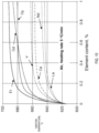
- FIGS. 2 A through 2 D compared to the known alloy WE43, some of the alloys developed in accordance with the present disclosure show signification reduction in hot tearing, as measured by a strain cracking index (SCI, also referred to as solidification cracking susceptibility (SCS)).
- SCI strain cracking index
- SCS solidification cracking susceptibility
- a select number of the newly-developed alloys that are disclosed herein are referred to in a shorthand manner, such as Alloy 1, Alloy 2, Alloy 3, Alloy 5 or Alloy 9.
- the alloys and methods disclosed herein promote improved hot-tearing resistance of a layer-by-layer generated component or related article that is not achievable in either conventional wrought or casting processes.
- the authors of the present disclosure have identified ways to reduce the likelihood of solidification cracking that can arise due to—among other things—the rapid cooling and associated solidification rate.
- the rapid solidification that is associated with certain forms of AM interferes with the normal cooling-related shrinkage and thermal contraction of a heated material in a semi-solid state by not providing adequate amounts of material that is still in its liquid state to the grain boundaries. When the liquid becomes trapped between dendrite arms, it causes stress resulting from the lower density of the liquid when compared to the solid.
- the SCS or SCI is related to the ability of the liquid to move out of the area between dendrite arms when shrinkage occurs.
- liquid feeding ability is related to the slope of the temperature versus the square root of the solid fraction as defined by the Kou SCS model.
- the temperature versus the square root of the solid fraction is obtained using the Scheil-Gulliver solidification model and used to calculate the SCS.
- FIG. 2 B a more detailed view of the region of interest from FIG. 2 A is shown. In it, the quantity
- the controller 190 may be configured to algorithmically predict the SCS by one or more of the aforementioned models. It will be appreciated that the foregoing analysis can be used to predict the SCS or SCI of any of the Alloy 1, Alloy 2, Alloy 3, Alloy 5 or Alloy 9 materials disclosed herein.
- FIGS. 2 C, and 2 D the relationship between SCI and total solid fraction is shown for the various alloys.
- the region of interest of FIG. 2 C is shown in greater detail in FIG. 2 D where the larger SCI numbers correspond to a high susceptibility to hot tearing H while the smaller SCI numbers correspond to a low susceptibility to hot tearing L.
- the microstructure influence on improved properties is shown for one of the Mg-based alloys developed herein.
- the as-deposited alloy (referred to herein as Alloy 1) is shown as an EDS mapping, including various bright phases segregated at grain boundary. Elemental charts shown to the right of each mapping indicate the corresponding percentages of various elements within the highlighted regions. Thus, the superimposed lines around the eutectic regions indicate the elemental distribution of the selected area to show how phases have formed post-solidification, while also showing with particularity the respective compositions of those individual phases.
- grain size, grain morphology (equiaxed), distribution of intermetallic and eutectic phases in the inter and intragrain or cell boundaries are factors that may be relied upon, as are the elemental composition of the phases formed.
- This data can be used for several predictions, such as phase field modeling, advancing the aforementioned CALPHAD databases, strength predictions or the like.
- the EDS investigation reveals the presence of Y, Ca and Er elements at the grain boundary regions which are forming these phases. Also, the EDS confirms the presence of Y, Nd and Er to influence the process of grain refinement and formation of the strengthening precipitate phase such as Mg 41 (Nd, Er) 5 and Mg 24 (Y, Er) 5 . EDS also reveals the formation of nano-size Zr-rich precipitates forming close to the grain boundary. The coarser flakes also contained Zr along with the main rare earths Nd, Er and Y, while the finer oxygen-rich flakes exhibiting the highest aspect ratio among all the secondary phases in the microstructure contained only Zr and Y, with no sign of Er or Ca.
- an XRD pattern of Alloy 1 in as-deposited and heat-treated conditions is shown.
- the XRD techniques shown here confirm the presence of Y, Nd and Er to influence the process of grain refinement and formation of the strengthening precipitate phase such as Mg 41 (Nd, Er) 5 and Mg 24 (Y, Er) 5 .
- the formation of yttrium oxide (Y 2 O 3 ) is confirmed, where the intensity increased gradually in the heat-treated condition.
- EDS mapping was used to investigate the elements present in the microstructure of an as-deposited and heat-treated sample, respectively.
- the mapping revealed the segregation of Y at the grain boundary regions of this microstructure, forming this bright continuous phase.
- EDS results show that the grain boundary regions are rich with Y, Nd and bright nanoscale precipitates are rich with Zr for Alloy 5.
- This mapping also shows that Nd is distributed into the Mg matrix uniformly, while the presence of nano precipitates rich with Zr at dendrite and grain boundaries is also in evidence.
- elemental charts shown to the right of each mapping indicate the corresponding percentages of various elements within the highlighted regions.
- the mapping revealed an increase in grain size compared to the as-deposited microstructure. Bright Y-rich phases are present in the grain boundary regions, even after heat treatment.
- FIG. 7 improved compressive yield strength of some of the present Mg-based alloys in the as-deposited condition are shown relative to legacy alloys such as AZ31 and AZ91C after a T6 heat-treatment.
- legacy alloys such as AZ31 and AZ91C
- the compression and tensile results reveal that the AM fabricated Mg alloys that are disclosed herein have better room temperature tensile and compressive strengths than legacy alloys such as AZ31 and AZ91C.
- the authors of the present disclosure believe that with the proper alloy and AM process, components may be manufactured that exhibit properties that are significantly better than existing Mg alloys; in one non-limiting example, YS of greater than 285 MPa is believed to be attainable, as are UTS of greater than 405 MPa along with elongation (EL) of greater than 8% at alloy densities of less than 2.3 g/cc. Moreover, flammability and corrosion resistance is expected by be enhanced relative to legacy alloys and conventional manufacturing processes.
- an experimental setup of for measuring the flammability of Mg-based alloys First a sample of one of the Mg-based alloys is formed, after which it is placed in a furnace, ignited and then analyzed to determine how much metal oxide remains.
- the experimental procedure as shown includes the use of a thermocouple attached to the core of the sample to ensure an uninterrupted contact and an accurate measurement of the temperature evolution.
- thermocouple data from the flammability experiments show an abbreviated time duration to focus on the region where the ignition occurs.
- literature data on the ignition temperature of various legacy alloys disregards the time to ignition.
- FIGS. 9 B through 9 D in the Mg-based alloys of the present disclosure, the temperature vs time curves represented in the plot extend from temperatures of approximately 1200° F. (649° C.) and higher.
- Each of these alloys (Alloy 1, Alloy 5 and Alloy 9) show higher ignition temperature of compared to the legacy alloys.
- the portion of each of FIGS. 9 B, 9 C and 9 D are marked with a star to indicate the measured ignition point.
- the use of the non-rare earth Ca is seen as promising, due in part to its general availability and low cost along with the results that show that Ca is very effective in raising the ignition temperature of Mg alloys.
- additions of 0.27-5.22 wt % Ca increased the ignition temperature of AZ91 alloy to 650° C., which is well with the temperature required to put it into the liquid state.
- the authors of the present disclosure have found that for Ca amounts of up to 5 wt %, the ignition temperature reached over 900° C., while significant growths were observed for even small amounts starting at around 0.5 wt % Ca.
- An alternative form of alloying with Ca may be performed via oxide dispersion CaO.
- FIG. 11 SEM micrographs that depict eutectic phases for both as-deposited and heat-treated samples are shown. In particular, the formation of bright phases around the grain boundary in some regions of the microstructure can be seen. High magnification images show the continuous formation of these bright phases at grain boundaries.
- intermetallic phases such as Mg3Gd, Mg3(Nd,Er), Mg24+x(Y,Er)5, Mg41(Nd,Er)5 and Mg45.9Gd9.08 can form eutectic with the primary Mg phase.
- FIG. 13 in conjunction with FIG. 1 , although it is the DED process that is depicted in FIG. 1 , the authors of the present disclosure have discovered that DMLS, SLM and SLS may be used to produce the Mg-based alloys disclosed herein.
- a schematic of the LPBF/SLM process is shown, where the laser-based heat source is applied to particles contained within a powder bed (often in an inert atmosphere) such that a layer-by-layer buildup occurs.
- This process is particularly beneficial for use in high-value components, particularly those with complex geometries and relatively low production volume, such as airfoils for gas turbine engines.
- the deposited material (for example, in powder form) is impacted by the concentrated energy beam 120 such that subsequent processing and sintered layers are defined.
- the material may take on various forms, including molten, re-melted and solidified.
- the use of the prepositional phrase “at least one of” is deemed to be an open-ended expression that has both conjunctive and disjunctive attributes.
- a claim that states “at least one of A, B and C” means A alone, B alone, C alone, A and B together, A and C together, B and C together, or A, B and C together.
- the singular forms “a,” “an” and “the” include plural references unless the context clearly dictates otherwise.
- the modifier “about” used in connection with a quantity is inclusive of the stated value and has the meaning dictated by the context (for example, it includes at least the degree of error associated with the measurement of the particular quantity).
- the modifier “about” should also be considered as disclosing the range defined by the absolute values of the two endpoints. For example, the expression “from about 2 to about 4” also discloses the range “from 2 to 4.”
- the term “about” may refer to plus or minus 10% of the indicated number. For example, “about 10%” may indicate a range of 9% to 11%, and “about 1” may mean from 0.9 to 1.1. Other meanings of “about” may be apparent from the context, such as rounding off, so, for example “about 1” may also mean from 0.5 to 1.4.
- each intervening number there between with the same degree of precision is explicitly contemplated.
- the numbers 7 and 8 are contemplated in addition to 6 and 9, and for the range 6.0 to 7.0, the number 6.0, 6.1, 6.2, 6.3, 6.4, 6.5, 6.6, 6.7, 6.8, 6.9 and 7.0 are explicitly contemplated.
Landscapes
- Chemical & Material Sciences (AREA)
- Engineering & Computer Science (AREA)
- Materials Engineering (AREA)
- Manufacturing & Machinery (AREA)
- Mechanical Engineering (AREA)
- Metallurgy (AREA)
- Organic Chemistry (AREA)
- Physics & Mathematics (AREA)
- Plasma & Fusion (AREA)
- Thermal Sciences (AREA)
- Powder Metallurgy (AREA)
Abstract
Description
Where fs and T are the total solid fraction and temperature, respectively.
Thus, increasing
near fs 1/2=1 increases the crack susceptibility by decreasing the growth rate dR/dt (growth rate of grains) that is needed for the grains to bond together to resist cracking. It also increases the length of the liquid channel along the grain boundary. A longer grain boundary channel hinders the liquid feeding that is needed to fill the grain boundary to resist cracking. In fact, from a mechanics point of view, a longer grain boundary channel is also easier to open up and propagate under tension.
near fs 1/2=1 can be used as an index for the SCS, that is, the steeper the slope of the T−fs 1/2 curve near fs 1/2=1 is, the greater the crack susceptibility. In one form, the susceptibility of a certain Mg-based alloy to hot tear cracking may be formed into an index as a straightforward way to compare the alloys against legacy alloys. In one form, the
| TABLE 1 | |||||
| Ultimate | |||||
| Tensile | |||||
| As-Deposited | Yield Strength | Strength | Elongation | ||
| Alloys | (MPa) | (MPa) | (%) | ||
| |
128.7 | 192.6 | 7.89 | ||
| |
120.5 | 204.6 | 9.75 | ||
| |
111.4 | 166.4 | 5.32 | ||
| Alloy 4 | 106.7 | 157.5 | 4.99 | ||
Claims (9)
Priority Applications (1)
| Application Number | Priority Date | Filing Date | Title |
|---|---|---|---|
| US17/738,648 US12054812B2 (en) | 2021-05-07 | 2022-05-06 | Magnesium alloy |
Applications Claiming Priority (2)
| Application Number | Priority Date | Filing Date | Title |
|---|---|---|---|
| US202163185825P | 2021-05-07 | 2021-05-07 | |
| US17/738,648 US12054812B2 (en) | 2021-05-07 | 2022-05-06 | Magnesium alloy |
Publications (2)
| Publication Number | Publication Date |
|---|---|
| US20230044652A1 US20230044652A1 (en) | 2023-02-09 |
| US12054812B2 true US12054812B2 (en) | 2024-08-06 |
Family
ID=85153229
Family Applications (1)
| Application Number | Title | Priority Date | Filing Date |
|---|---|---|---|
| US17/738,648 Active 2042-06-09 US12054812B2 (en) | 2021-05-07 | 2022-05-06 | Magnesium alloy |
Country Status (1)
| Country | Link |
|---|---|
| US (1) | US12054812B2 (en) |
Families Citing this family (2)
| Publication number | Priority date | Publication date | Assignee | Title |
|---|---|---|---|---|
| CN117182251A (en) * | 2023-10-11 | 2023-12-08 | 中北大学 | A forming method of Mg-9.2Gd-3.2Y-2Zn-0.4Zr alloy |
| CN117259786A (en) * | 2023-10-31 | 2023-12-22 | 吉林大学 | A selective laser melting forming method that synergistically improves the strength and plasticity of magnesium alloys |
Citations (3)
| Publication number | Priority date | Publication date | Assignee | Title |
|---|---|---|---|---|
| US20170072103A1 (en) * | 2014-05-05 | 2017-03-16 | The University Of Toledo | Biodegradable Magnesium Alloys and Composites |
| US20190153570A1 (en) * | 2016-01-19 | 2019-05-23 | Qian Zhou | Fully degradable magnesium alloy and preparation method thereof |
| US20220154315A1 (en) * | 2019-02-20 | 2022-05-19 | Husqvarna Ab | A Magnesium Alloy, A Piston Manufactured by Said Magnesium Alloy and a Method for Manufacturing Said Piston |
-
2022
- 2022-05-06 US US17/738,648 patent/US12054812B2/en active Active
Patent Citations (3)
| Publication number | Priority date | Publication date | Assignee | Title |
|---|---|---|---|---|
| US20170072103A1 (en) * | 2014-05-05 | 2017-03-16 | The University Of Toledo | Biodegradable Magnesium Alloys and Composites |
| US20190153570A1 (en) * | 2016-01-19 | 2019-05-23 | Qian Zhou | Fully degradable magnesium alloy and preparation method thereof |
| US20220154315A1 (en) * | 2019-02-20 | 2022-05-19 | Husqvarna Ab | A Magnesium Alloy, A Piston Manufactured by Said Magnesium Alloy and a Method for Manufacturing Said Piston |
Also Published As
| Publication number | Publication date |
|---|---|
| US20230044652A1 (en) | 2023-02-09 |
Similar Documents
| Publication | Publication Date | Title |
|---|---|---|
| Zhang et al. | A novel crack-free Ti-modified Al-Cu-Mg alloy designed for selective laser melting | |
| Sun et al. | Electron beam additive manufacturing of Inconel 718 alloy rods: Impact of build direction on microstructure and high-temperature tensile properties | |
| JP7066884B2 (en) | Method for producing nanocrystal articles using additive manufacturing | |
| Croteau et al. | Microstructure and mechanical properties of Al-Mg-Zr alloys processed by selective laser melting | |
| Wang et al. | Selective laser melting of W-Ni-Cu composite powder: Densification, microstructure evolution and nano-crystalline formation | |
| Mosallanejad et al. | In-situ alloying of a fine grained fully equiaxed Ti-based alloy via electron beam powder bed fusion additive manufacturing process | |
| Fiocchi et al. | Low temperature annealing dedicated to AlSi10Mg selective laser melting products | |
| Ramakrishnan et al. | Microstructural control of an Al–W aluminum matrix composite during direct laser metal deposition | |
| JP6374939B2 (en) | Nickel-base superalloy and method for producing the same | |
| Dynin et al. | Structure and mechanical properties of an advanced aluminium alloy AlSi10MgCu (Ce, Zr) produced by selective laser melting | |
| Daram et al. | Microstructure and phase evolution of functionally graded multi-materials of Ni–Ti alloy fabricated by laser powder bed fusion process | |
| Ding et al. | Microstructural control of alloy 718 fabricated by electron beam melting with expanded processing window by adaptive offset method | |
| US12054812B2 (en) | Magnesium alloy | |
| Collins et al. | The influence of the enthalpy of mixing during the laser deposition of complex titanium alloys using elemental blends | |
| CN110832093A (en) | Aluminum alloys for additive technology | |
| Zhang et al. | Effect of C addition on microstructure and mechanical properties of laser micro-alloying Ti–Al–V–C titanium matrix composites | |
| Ryou et al. | Microstructural evolution and hot cracking prevention in direct-laser-deposited Ni-based superalloy through Hf addition | |
| Fereiduni et al. | Process-structure-property relationships in additively manufactured metal matrix composites | |
| JP2022148950A (en) | Method for manufacturing shaped object using Fe-based alloy powder | |
| Kimura et al. | Combined factors for enhanced high-temperature strength of Al-Mn-Cr heat-resistant alloy fabricated using laser-based powder bed fusion | |
| Daram et al. | Compositionally graded titanium to aluminum processed by laser powder bed fusion process: Microstructure evolution and mechanical properties | |
| Poddar et al. | Experimental investigation on microstructure and mechanical properties of gravity-die-cast magnesium alloys | |
| Zhang et al. | Laser powder micro-deposition of compositional gradient Ti–Cr alloy | |
| Ma et al. | Tailoring microstructure and oxidation resistance in directed energy deposited Inconel 625 alloy by the addition of submicron-ZrC particles | |
| Yadav et al. | Fabrication of promising material ‘titanium aluminide’: methods and issues (a status report) |
Legal Events
| Date | Code | Title | Description |
|---|---|---|---|
| FEPP | Fee payment procedure |
Free format text: ENTITY STATUS SET TO UNDISCOUNTED (ORIGINAL EVENT CODE: BIG.); ENTITY STATUS OF PATENT OWNER: SMALL ENTITY |
|
| AS | Assignment |
Owner name: MRL MATERIALS RESOURCES LLC, OHIO Free format text: ASSIGNMENT OF ASSIGNORS INTEREST;ASSIGNORS:SALEM, AYMAN A.;SATKO, DANIEL P.;RAMAKRISHNAN, ABHISHEK;SIGNING DATES FROM 20210510 TO 20210519;REEL/FRAME:059899/0147 |
|
| FEPP | Fee payment procedure |
Free format text: ENTITY STATUS SET TO SMALL (ORIGINAL EVENT CODE: SMAL); ENTITY STATUS OF PATENT OWNER: SMALL ENTITY |
|
| STPP | Information on status: patent application and granting procedure in general |
Free format text: NON FINAL ACTION MAILED |
|
| STPP | Information on status: patent application and granting procedure in general |
Free format text: FINAL REJECTION MAILED |
|
| STPP | Information on status: patent application and granting procedure in general |
Free format text: RESPONSE AFTER FINAL ACTION FORWARDED TO EXAMINER |
|
| STPP | Information on status: patent application and granting procedure in general |
Free format text: DOCKETED NEW CASE - READY FOR EXAMINATION |
|
| STPP | Information on status: patent application and granting procedure in general |
Free format text: NOTICE OF ALLOWANCE MAILED -- APPLICATION RECEIVED IN OFFICE OF PUBLICATIONS |
|
| ZAAA | Notice of allowance and fees due |
Free format text: ORIGINAL CODE: NOA |
|
| ZAAB | Notice of allowance mailed |
Free format text: ORIGINAL CODE: MN/=. |
|
| STPP | Information on status: patent application and granting procedure in general |
Free format text: PUBLICATIONS -- ISSUE FEE PAYMENT VERIFIED |
|
| STCF | Information on status: patent grant |
Free format text: PATENTED CASE |