US12054243B2 - Rotary-wing aircraft - Google Patents
Rotary-wing aircraft Download PDFInfo
- Publication number
- US12054243B2 US12054243B2 US17/222,603 US202117222603A US12054243B2 US 12054243 B2 US12054243 B2 US 12054243B2 US 202117222603 A US202117222603 A US 202117222603A US 12054243 B2 US12054243 B2 US 12054243B2
- Authority
- US
- United States
- Prior art keywords
- damper
- mass
- stiffness
- fuselage
- rotary
- Prior art date
- Legal status (The legal status is an assumption and is not a legal conclusion. Google has not performed a legal analysis and makes no representation as to the accuracy of the status listed.)
- Active, expires
Links
- 230000007246 mechanism Effects 0.000 claims abstract description 35
- 230000004044 response Effects 0.000 claims abstract description 31
- 230000008859 change Effects 0.000 claims abstract description 8
- 230000007423 decrease Effects 0.000 claims description 16
- 230000008878 coupling Effects 0.000 claims description 3
- 238000010168 coupling process Methods 0.000 claims description 3
- 238000005859 coupling reaction Methods 0.000 claims description 3
- 239000002828 fuel tank Substances 0.000 description 25
- 230000003247 decreasing effect Effects 0.000 description 19
- 239000012530 fluid Substances 0.000 description 18
- 239000011553 magnetic fluid Substances 0.000 description 14
- 238000013016 damping Methods 0.000 description 12
- 238000000034 method Methods 0.000 description 11
- 238000012545 processing Methods 0.000 description 11
- 239000000446 fuel Substances 0.000 description 7
- 239000003795 chemical substances by application Substances 0.000 description 5
- XLYOFNOQVPJJNP-UHFFFAOYSA-N water Substances O XLYOFNOQVPJJNP-UHFFFAOYSA-N 0.000 description 5
- 238000010586 diagram Methods 0.000 description 4
- 239000003905 agrochemical Substances 0.000 description 3
- 238000006073 displacement reaction Methods 0.000 description 2
- 238000005265 energy consumption Methods 0.000 description 2
- 239000006249 magnetic particle Substances 0.000 description 2
- 239000000463 material Substances 0.000 description 2
- 239000000575 pesticide Substances 0.000 description 2
- 230000001141 propulsive effect Effects 0.000 description 2
- 229920002430 Fibre-reinforced plastic Polymers 0.000 description 1
- 239000006096 absorbing agent Substances 0.000 description 1
- 238000010521 absorption reaction Methods 0.000 description 1
- 230000001133 acceleration Effects 0.000 description 1
- 230000004075 alteration Effects 0.000 description 1
- 238000013459 approach Methods 0.000 description 1
- 230000005540 biological transmission Effects 0.000 description 1
- 230000008602 contraction Effects 0.000 description 1
- 238000001514 detection method Methods 0.000 description 1
- 239000006185 dispersion Substances 0.000 description 1
- 230000000694 effects Effects 0.000 description 1
- 239000011151 fibre-reinforced plastic Substances 0.000 description 1
- 238000010304 firing Methods 0.000 description 1
- 238000007667 floating Methods 0.000 description 1
- 239000007788 liquid Substances 0.000 description 1
- 238000005259 measurement Methods 0.000 description 1
- 239000007769 metal material Substances 0.000 description 1
- 238000012986 modification Methods 0.000 description 1
- 230000004048 modification Effects 0.000 description 1
- 230000003287 optical effect Effects 0.000 description 1
- 230000008569 process Effects 0.000 description 1
- 230000009467 reduction Effects 0.000 description 1
- 230000035939 shock Effects 0.000 description 1
- 239000007921 spray Substances 0.000 description 1
- 238000005507 spraying Methods 0.000 description 1
- 230000002123 temporal effect Effects 0.000 description 1
Images


Classifications
-
- B—PERFORMING OPERATIONS; TRANSPORTING
- B64—AIRCRAFT; AVIATION; COSMONAUTICS
- B64C—AEROPLANES; HELICOPTERS
- B64C27/00—Rotorcraft; Rotors peculiar thereto
- B64C27/001—Vibration damping devices
-
- B—PERFORMING OPERATIONS; TRANSPORTING
- B64—AIRCRAFT; AVIATION; COSMONAUTICS
- B64C—AEROPLANES; HELICOPTERS
- B64C27/00—Rotorcraft; Rotors peculiar thereto
- B64C27/04—Helicopters
-
- B—PERFORMING OPERATIONS; TRANSPORTING
- B64—AIRCRAFT; AVIATION; COSMONAUTICS
- B64D—EQUIPMENT FOR FITTING IN OR TO AIRCRAFT; FLIGHT SUITS; PARACHUTES; ARRANGEMENT OR MOUNTING OF POWER PLANTS OR PROPULSION TRANSMISSIONS IN AIRCRAFT
- B64D1/00—Dropping, ejecting, releasing or receiving articles, liquids, or the like, in flight
- B64D1/02—Dropping, ejecting, or releasing articles
-
- B—PERFORMING OPERATIONS; TRANSPORTING
- B64—AIRCRAFT; AVIATION; COSMONAUTICS
- B64D—EQUIPMENT FOR FITTING IN OR TO AIRCRAFT; FLIGHT SUITS; PARACHUTES; ARRANGEMENT OR MOUNTING OF POWER PLANTS OR PROPULSION TRANSMISSIONS IN AIRCRAFT
- B64D1/00—Dropping, ejecting, releasing or receiving articles, liquids, or the like, in flight
- B64D1/16—Dropping or releasing powdered, liquid, or gaseous matter, e.g. for fire-fighting
-
- B—PERFORMING OPERATIONS; TRANSPORTING
- B64—AIRCRAFT; AVIATION; COSMONAUTICS
- B64D—EQUIPMENT FOR FITTING IN OR TO AIRCRAFT; FLIGHT SUITS; PARACHUTES; ARRANGEMENT OR MOUNTING OF POWER PLANTS OR PROPULSION TRANSMISSIONS IN AIRCRAFT
- B64D37/00—Arrangements in connection with fuel supply for power plant
- B64D37/32—Safety measures not otherwise provided for, e.g. preventing explosive conditions
-
- B—PERFORMING OPERATIONS; TRANSPORTING
- B64—AIRCRAFT; AVIATION; COSMONAUTICS
- B64D—EQUIPMENT FOR FITTING IN OR TO AIRCRAFT; FLIGHT SUITS; PARACHUTES; ARRANGEMENT OR MOUNTING OF POWER PLANTS OR PROPULSION TRANSMISSIONS IN AIRCRAFT
- B64D7/00—Arrangement of military equipment, e.g. armaments, armament accessories or military shielding, in aircraft; Adaptations of armament mountings for aircraft
- B64D7/08—Arrangement of rocket launchers
-
- F—MECHANICAL ENGINEERING; LIGHTING; HEATING; WEAPONS; BLASTING
- F16—ENGINEERING ELEMENTS AND UNITS; GENERAL MEASURES FOR PRODUCING AND MAINTAINING EFFECTIVE FUNCTIONING OF MACHINES OR INSTALLATIONS; THERMAL INSULATION IN GENERAL
- F16F—SPRINGS; SHOCK-ABSORBERS; MEANS FOR DAMPING VIBRATION
- F16F15/00—Suppression of vibrations in systems; Means or arrangements for avoiding or reducing out-of-balance forces, e.g. due to motion
- F16F15/002—Suppression of vibrations in systems; Means or arrangements for avoiding or reducing out-of-balance forces, e.g. due to motion characterised by the control method or circuitry
-
- F—MECHANICAL ENGINEERING; LIGHTING; HEATING; WEAPONS; BLASTING
- F16—ENGINEERING ELEMENTS AND UNITS; GENERAL MEASURES FOR PRODUCING AND MAINTAINING EFFECTIVE FUNCTIONING OF MACHINES OR INSTALLATIONS; THERMAL INSULATION IN GENERAL
- F16F—SPRINGS; SHOCK-ABSORBERS; MEANS FOR DAMPING VIBRATION
- F16F2228/00—Functional characteristics, e.g. variability, frequency-dependence
- F16F2228/04—Frequency effects
-
- F—MECHANICAL ENGINEERING; LIGHTING; HEATING; WEAPONS; BLASTING
- F16—ENGINEERING ELEMENTS AND UNITS; GENERAL MEASURES FOR PRODUCING AND MAINTAINING EFFECTIVE FUNCTIONING OF MACHINES OR INSTALLATIONS; THERMAL INSULATION IN GENERAL
- F16F—SPRINGS; SHOCK-ABSORBERS; MEANS FOR DAMPING VIBRATION
- F16F2228/00—Functional characteristics, e.g. variability, frequency-dependence
- F16F2228/06—Stiffness
- F16F2228/066—Variable stiffness
-
- F—MECHANICAL ENGINEERING; LIGHTING; HEATING; WEAPONS; BLASTING
- F16—ENGINEERING ELEMENTS AND UNITS; GENERAL MEASURES FOR PRODUCING AND MAINTAINING EFFECTIVE FUNCTIONING OF MACHINES OR INSTALLATIONS; THERMAL INSULATION IN GENERAL
- F16F—SPRINGS; SHOCK-ABSORBERS; MEANS FOR DAMPING VIBRATION
- F16F2230/00—Purpose; Design features
- F16F2230/18—Control arrangements
-
- F—MECHANICAL ENGINEERING; LIGHTING; HEATING; WEAPONS; BLASTING
- F16—ENGINEERING ELEMENTS AND UNITS; GENERAL MEASURES FOR PRODUCING AND MAINTAINING EFFECTIVE FUNCTIONING OF MACHINES OR INSTALLATIONS; THERMAL INSULATION IN GENERAL
- F16F—SPRINGS; SHOCK-ABSORBERS; MEANS FOR DAMPING VIBRATION
- F16F9/00—Springs, vibration-dampers, shock-absorbers, or similarly-constructed movement-dampers using a fluid or the equivalent as damping medium
- F16F9/32—Details
- F16F9/50—Special means providing automatic damping adjustment, i.e. self-adjustment of damping by particular sliding movements of a valve element, other than flexions or displacement of valve discs; Special means providing self-adjustment of spring characteristics
- F16F9/512—Means responsive to load action, i.e. static load on the damper or dynamic fluid pressure changes in the damper, e.g. due to changes in velocity
- F16F9/5123—Means responsive to load action, i.e. static load on the damper or dynamic fluid pressure changes in the damper, e.g. due to changes in velocity responsive to the static or steady-state load on the damper
-
- F—MECHANICAL ENGINEERING; LIGHTING; HEATING; WEAPONS; BLASTING
- F16—ENGINEERING ELEMENTS AND UNITS; GENERAL MEASURES FOR PRODUCING AND MAINTAINING EFFECTIVE FUNCTIONING OF MACHINES OR INSTALLATIONS; THERMAL INSULATION IN GENERAL
- F16F—SPRINGS; SHOCK-ABSORBERS; MEANS FOR DAMPING VIBRATION
- F16F9/00—Springs, vibration-dampers, shock-absorbers, or similarly-constructed movement-dampers using a fluid or the equivalent as damping medium
- F16F9/32—Details
- F16F9/53—Means for adjusting damping characteristics by varying fluid viscosity, e.g. electromagnetically
- F16F9/535—Magnetorheological [MR] fluid dampers
-
- Y—GENERAL TAGGING OF NEW TECHNOLOGICAL DEVELOPMENTS; GENERAL TAGGING OF CROSS-SECTIONAL TECHNOLOGIES SPANNING OVER SEVERAL SECTIONS OF THE IPC; TECHNICAL SUBJECTS COVERED BY FORMER USPC CROSS-REFERENCE ART COLLECTIONS [XRACs] AND DIGESTS
- Y02—TECHNOLOGIES OR APPLICATIONS FOR MITIGATION OR ADAPTATION AGAINST CLIMATE CHANGE
- Y02T—CLIMATE CHANGE MITIGATION TECHNOLOGIES RELATED TO TRANSPORTATION
- Y02T50/00—Aeronautics or air transport
- Y02T50/40—Weight reduction
Definitions
- the disclosure relates to a rotary-wing aircraft.
- various external devices for instance, a fuel tank, a storage pod
- a fuel tank for instance, a fuel tank, a storage pod
- JP-A No. 2002-029499 describes a helicopter in which storage pods are mounted via an adapter on the right and left sides of the fuselage, and a storage pod for relay is mounted via another adapter on the lower side of the fuselage.
- the storage pods are suspended and supported by a damper tube from an upper side of the fuselage to stably maintain the state of the storage pods mounted on the fuselage.
- An aspect of the disclosure provides a rotary-wing aircraft.
- This includes a fuselage, and an external device.
- the fuselage is provided with a rotary wing.
- the external device mounted on an outside of the fuselage.
- the external device includes a mounting device, a mass variation device, and a damper.
- the mounting device is fixed to the fuselage and disposed so as to project in a lateral direction of the fuselage.
- the mass variation device is mounted on the mounting device and has mass that varies as the mass variation device is used.
- the damper couples the fuselage to the mounting device and supports the mounting device.
- the damper includes a stiffness variable mechanism configured to change stiffness of the damper in response to variation in the mass of the mass variation device.
- FIG. 1 is a side view illustrating a helicopter according to an embodiment of the disclosure
- FIG. 2 is a plan view illustrating the helicopter according to the embodiment
- FIG. 3 is a front view illustrating the helicopter according to the embodiment.
- FIG. 4 is a front view schematically illustrating external devices mounted on the outside of the fuselage of the helicopter according to the embodiment
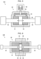
- FIG. 5 is a schematic diagram illustrating an example of a hydraulic damper including a stiffness variable mechanism according to the embodiment
- FIG. 6 is a schematic diagram illustrating an example of a magneto-rheological damper including the stiffness variable mechanism according to the embodiment
- FIG. 7 is a timing chart illustrating a variation of the natural frequency of an external device when the stiffness of the damper is not controlled according to a reference example
- FIG. 8 is a timing chart illustrating a variation of the natural frequency of an external device when the stiffness of the damper is controlled by a controller according to the embodiment
- FIG. 9 is a timing chart illustrating a variation of the natural frequency of an external device when the stiffness of the damper is controlled by a controller according to the embodiment.
- FIG. 10 is a flowchart illustrating a method of controlling the stiffness of the damper by the controller according to the embodiment
- FIG. 11 is a graph illustrating a specific example of amplitude data for every time interval according to the embodiment.
- FIG. 12 is a graph illustrating a specific example of amplitude data for every frequency interval according to the embodiment.
- the blades of a rotor rotate at a substantially constant number of revolutions, and vibration occurs mainly in the rotor hub, the vibration having a frequency equal to the number of revolutions multiplied by the number of the blades.
- the rotor in rotation becomes a source of vibration, and the whole fuselage vibrates at a predetermined frequency.
- the natural frequency of the external device changes in response to variation of the mass of the external device.
- the external device includes a fuel tank
- use of the fuel in the fuel tank during the operation of the helicopter reduces the mass of the fuel tank, and the natural frequency of the fuel tank is thus increased.
- the natural frequency of the external device may fall, during the operation of the helicopter, within a range of frequency which causes resonance with the fuselage vibration accompanied by the rotation of the rotor.
- the helicopter 1 is, for example, a single rotor helicopter including the fuselage 2 provided with one main rotor 4 .
- the helicopter may be a twin rotor helicopter with multiple main rotors (for example, a coaxial rotor helicopter, a tandem rotor helicopter, a side-by-side rotor helicopter, an intermeshing rotor helicopter, or a multi-rotor helicopter with three or more rotors).
- the main rotor 4 is a rotary wing to obtain power, such as aerodynamic lift and a moving-directional propulsive force for the helicopter 1 , and is provided on the upper side of the fuselage 2 .
- the main rotor 4 includes a rotor shaft coupled to a rotational driving force generator such as an engine, a rotor hub mounted on the rotor shaft, and multiple blades 3 radially mounted on the rotor hub. Although four blades 3 are provided in the embodiment, the number of blades may be two or greater than or equal to four.
- the main rotor 4 is rotated by, for example, an engine and the trajectory surface (rotary disk surface) of multiple blades 3 is changed, and thus the aerodynamic lift and the moving-directional propulsive force for the helicopter 1 are changed. Consequently, the helicopter 1 can fly in various flight states (for example, floating, descending, hovering, forward moving, rearward moving, and turning).
- FIG. 4 is a front view schematically illustrating the external devices 10 to be mounted on the outside of the fuselage 2 of the helicopter 1 according to the embodiment.
- the external devices 10 are mounted on the outside of the fuselage 2 of the helicopter 1 .
- Each external device 10 is an additional device to be optionally mounted as appropriate to add an additional function to the helicopter 1 .
- the external device 10 is detachably mounted on the outside of the fuselage 2 .
- Each external device 10 is disposed on the lateral side of the fuselage 2 to project outwardly of the fuselage 2 in a right-left direction. Although two external devices 10 , 10 are provided on the right and left sides of the fuselage 2 in the embodiment, a single external device 10 may be provided on one side (either one of a left side or a right side) of the fuselage 2 .
- the external device 10 includes a mounting device 12 , a mass variation device 14 , and a damper 16 .
- the mounting device 12 is a mounting member for mounting the mass variation device 14 to the fuselage 2 .
- the mounting device 12 is fixed to the lateral face on the lateral side (the left side or the right side) of the fuselage 2 and is disposed to project in a lateral direction of the fuselage 2 .
- the mounting device 12 can have any shape as long as the shape allows the mass variation device 14 to be mounted.
- the mounting device 12 is made of a material (for example, metal materials or fiber-reinforced plastics) having strength to be able to stably support the mass variation device 14 mounted.
- the mounting device 12 is made of, for example, a plate-like or frame-like member having a substantially L-shaped cross-section.
- One end (base side) of the mounting device 12 is fixed to a hard point of the lateral face of the fuselage 2 , and the other end (mounting side) of the mounting device 12 is disposed to project laterally in a substantially horizontal direction of the fuselage 2 .
- the mounting device 12 is disposed so as to project to the right and left sides from the fuselage 2 in this manner, and thus the mass variation device 14 can be easily mounted on the lower surface or the upper surface of the mounting device 12 .
- an existing device such as a stub wing pre-installed in the helicopter 1 may be utilized as the mounting device 12 .
- a fixing device such as an adapter for mounting the mass variation device 14 may be additionally newly installed as the mounting device 12 in the fuselage 2 .
- both right and left lateral sides of the fuselage 2 are each provided with one mounting device 12 .
- the configuration is not limited to such an example.
- one or multiple mounting devices 12 may be provided on either one of the lateral sides of the fuselage 2 , or multiple mounting devices 12 may be provided on both the lateral sides of the fuselage 2 .
- the mass variation device 14 is an additional device mounted on the fuselage 2 and provides an additional function to the helicopter 1 .
- the mass variation device 14 is a device whose mass varies with its use.
- the mass variation device 14 may be, for example, a fuel tank, a water sprayer, a fire extinguishing agent sprayer, an agricultural chemical sprayer, a storage device which stores various cargoes, or various weapons (for example, a missile launcher, a rocket launcher, a gun pod, and a mine dispersion device).
- the mass of the mass variation device 14 When the function of such mass variation device 14 is used during flight of the helicopter 1 , the mass of the mass variation device 14 itself is decreased, and, as a result, the mass of the whole external device 10 is also decreased.
- the mass variation device 14 is a fuel tank
- use of the fuel stored in the fuel tank during flight of the helicopter 1 causes the mass of the fuel tank to be decreased by the amount of consumption of fuel.
- the mass variation device 14 is a water sprayer, a sprayer such as a fire extinguishing agent sprayer, or an agricultural chemical sprayer
- spraying an object to be sprayed such as water, fire extinguishing agent, pesticide
- the mass variation device 14 is a weapon, firing a missile, a rocket, or a bullet from the weapon during flight of the helicopter 1 causes the mass of the weapon to be decreased by the mass of the fired missile, rocket, or bullet.
- the mass variation device 14 is a fuel tank.
- the mass variation device of the disclosure is not limited to the example of a fuel tank, and may be one of the above-mentioned various devices (such as a sprayer, a storage device, and a weapon) as long as the mass variation device has a mass which varies with its use.
- the mass variation device 14 is detachably mounted on the mounting device 12 . Therefore, when the additional function of the mass variation device 14 is used, the mass variation device 14 is simply mounted, thus the versatility of the helicopter 1 increases, and the helicopter 1 can be reduced in weight.
- the mass variation device 14 mounted on the mounting device 12 can be replaced by one of multiple different mass variation devices 14 to be mounted on the fuselage 2 , thus a variety of additional functions can be optionally added to the helicopter 1 .
- the damper 16 is a vibration absorption device that supports the mounting device 12 on which the mass variation device 14 mounted, and attenuates the vibration of the mounting device 12 .
- the damper 16 When being displaced due to the vibration of the mounting device 12 , the damper 16 generates resistance and converts the kinetic energy of the vibration into heat to attenuate the vibration.
- the resistance generated in the damper 16 is referred to as a damping force.
- a hydraulic pressure damper utilizing viscous resistance of fluid such as an oil
- a magneto-rheological damper utilizing resistance of fluid such as a magneto-rheological fluid
- the damper 16 couples one of the right and left lateral sides of the fuselage 2 to the mounting device 12 and supports the mounting device 12 .
- One end of the damper 16 is fixed to the lateral face of the fuselage 2 , and the other end of the damper 16 is fixed to the mounting device 12 .
- the damper 16 is, in some embodiments, made of a cylinder damper telescopic in the axial direction (longitudinal direction) of the cylinder, for example.
- the cylinder damper has a structure in which a tube that stores a cylinder rod and a piston is filled with fluid, such as an oil, and the fluid flows in the tube by movement of the piston according to expansion and contraction of the cylinder rod.
- the path of movement of the fluid is provided with a port (a hole with a small flow path area) having an orifice or a valve, viscous resistance occurs when the fluid passes through the port, and thus a damping force is obtained.
- the damper 16 can absorb and attenuate the vibration by utilizing the viscous resistance of the fluid.
- the viscous resistance of the fluid can be increased or decreased by changing the flow path area of the above-mentioned port having an orifice or a valve.
- the damping force on the vibration by using the damper 16 in other words, the stiffness (spring constant k) of the damper 16 can be controlled.
- two dampers 16 are installed in one mounting device 12 provided on one side of the fuselage 2 , and the one mounting device 12 is supported by the two dampers 16 .
- one damper 16 may be set to one mounting device 12 , or three of more dampers 16 may be set to one mounting device 12 .
- the mass variation device 14 is detachably mounted on the lower side of the mounting device 12 and is suspended by the mounting device 12 .
- the damper 16 is disposed on the upper side of the mounting device 12 .
- One end (the end near the fuselage 2 ) of the damper 16 is fixed to the lateral face of the fuselage 2 at a position higher than the mounting device 12 , and the other end (the end on the outer side of the fuselage 2 in the right-left direction) of the damper 16 is fixed to the upper side (for example, the upper surface) of the mounting device 12 .
- the damper 16 suspends from an upper position the mounting device 12 on which the mass variation device 14 is mounted and supports the mounting device 12 .
- the mounting structure is a structure in which the damper 16 is disposed on the upper side of the mounting device 12 , and the mass variation device 14 is suspended from the lower side of the mounting device 12 .
- the damper 16 does not interfere with operations when the mass variation device 14 is mounted or dismounted on or from the mounting device 12 or when the mass variation device 14 is used.
- the mass variation device 14 can be disposed on the lower side of the mounting device 12 .
- the mass variation device 14 is a sprayer or a weapon
- an object to be sprayed such as water, pesticide, fire extinguishing agent
- a weapon is easily fired from the mass variation device 14 to a position below the fuselage 2 .
- the structure is not limited to the example of the above-described mounting structure.
- the mounting structure may be a structure in which the mass variation device 14 is disposed on the upper side of the mounting device 12 , the damper 16 is disposed on the lower side of the mounting device 12 , and the mounting device 12 is supported by the damper 16 from the lower side.
- the mounting structure may be a structure in which the mass variation device 14 is mounted on the front side or the rear side of the mounting device 12 which projects laterally from the fuselage 2 , and the damper 16 is disposed on the upper side or the lower side of the mounting device 12 .
- a stiffness variable mechanism 20 provided in the damper 16 according to the embodiment and a controller 30 that controls the stiffness of the damper 16 using the stiffness variable mechanism 20 are described.
- the blades 3 of the main rotor 4 rotate at a substantially constant number of revolutions, and vibration occurs mainly in the rotor hub, the vibration having a frequency equal to the number of revolutions multiplied by the number of the blades.
- the main rotor 4 in rotation becomes a source of vibration, and the whole fuselage of the helicopter 1 vibrates at a substantially constant frequency.
- the vibration of the fuselage 2 accompanied by the rotation of the main rotor 4 is referred to as “fuselage vibration”, and the frequency of the fuselage vibration is referred to as the “fuselage frequency”.
- the natural frequency of the external device 10 mounted on the outside of the fuselage 2 is varied, for example, by the mass and stiffness of the external device 10 .
- the natural frequency of the external device 10 is also varied in response to variation in the mass.
- the natural frequency of the external device 10 may fall within a range of resonance with the fuselage vibration (a range of frequency in which the external device 10 resonates with the fuselage vibration).
- the external device 10 resonates with the fuselage vibration, vibrates with a large amplitude, and thus stable flight may be obstructed.
- the damper 16 is provided with the stiffness variable mechanism 20 with which the stiffness of the damper 16 is controlled in response to variation in the mass of the mass variation device 14 .
- the controller 30 that controls the stiffness variable mechanism 20
- various sensors that obtain information to be used for the control are provided in the embodiment.
- the sensors include, for example, a sensor that detects information on the mass of the mass variation device 14 , and a sensor that obtains information on the vibration of the external device 10 including the mounting device 12 and the mass variation device 14 .
- the controller 30 includes, for example, an arithmetic processing unit, such as a central processing unit (CPU) or a micro processing unit (MPU), and an image processing device, such as a graphic processing unit (GPU).
- the arithmetic processing unit performs various arithmetic processes by executing programs stored in a memory device. Note that part or all of the arithmetic processing unit may be updatable software such as firmware or may be a program module executable by a command from a CPU.
- the controller 30 controls the stiffness variable mechanism 20 and adjusts the stiffness of the damper 16 to an appropriate value, based on the results of detection made by the above-described various sensors and control information to control the mass variation device 14 .
- the stiffness and the natural frequency of the whole external device 10 are controlled by the controller 30 in response to variation in the mass of the mass variation device 14 , and thus the resonance of the external device 10 with the fuselage vibration can be reduced.
- the stiffness variable mechanism 20 is a mechanism to change the stiffness of the damper 16 and is provided in the damper 16 itself. During flight of the helicopter 1 , the stiffness variable mechanism 20 changes the stiffness of the damper 16 in response to variation in the mass of the mass variation device 14 .
- the helicopter 1 according to the embodiment includes the controller 30 that controls the stiffness variable mechanism 20 of the damper 16 .
- the controller 30 automatically controls the stiffness of the damper 16 by using the stiffness variable mechanism 20 in response to variation in the mass of the mass variation device 14 .
- the stiffness of the damper 16 is the axial stiffness in the direction in which the damper 16 expands and contracts (for example, in the axial direction (longitudinal direction) of the cylinder damper).
- the damping force by the damper 16 on the vibration can be changed by changing the stiffness of the damper 16 .
- the damper 16 couples the mounting device 12 , on which the mass variation device 14 is mounted, to the fuselage 2 , and supports the mounting device 12 and the mass variation device 14 .
- the stiffness of the external device 10 mounted on the outside of the fuselage 2 is controlled by changing the stiffness of the damper 16 , thereby enabling the natural frequency of the external device 10 to be controlled.
- the natural frequency Fn [Hz] of an object in a single-degree-of-freedom system is represented by the following Expression (1) using the mass m [kg] of the object and the stiffness (spring constant k [N/m]) of the object.
- Fn (1 ⁇ 2 ⁇ ) ⁇ (k/m) 0.5 (1)
- the natural frequency of the external device 10 may change and may fall within the resonance range with the fuselage vibration.
- the natural frequency of the external device 10 is controlled in response to variation in the mass of the mass variation device 14 so that the natural frequency of the external device 10 falls outside the resonance range. Consequently, the vibration of the external device 10 can be prevented from resonating with the fuselage vibration.
- the mass variation device 14 of the external device 10 is a fuel tank.
- the stiffness of the damper 16 remains substantially constant, when the mass of the fuel tank is decreased by use of the fuel in the fuel tank, the natural frequency of the external device 10 is gradually increased in response to the decrease of the mass. As a consequence, the natural frequency of the external device 10 may fall within the resonance range with the fuselage vibration, and the external device 10 may resonate.
- the controller 30 reduces the stiffness (spring constant k) of the damper 16 in response to decrease in the mass of the fuel tank by controlling the stiffness variable mechanism 20 .
- the natural frequency of the external device 10 can be maintained at a substantially constant value by reducing the increase in the natural frequency. Therefore, even when the mass of the fuel tank is varied, the natural frequency of the external device 10 can be controlled so as to fall outside the resonance range, thus resonance between the external device 10 and the fuselage vibration can be prevented.
- the controller 30 controls the natural frequency of the external device 10 to fall outside the resonance range by controlling the stiffness of the damper 16 in response to variation in the mass of the mass variation device 14 .
- the controller 30 obtains information on the vibration of the external device 10 or information on the mass of the mass variation device 14 , and detects a factor of variation in the natural frequency of the external device 10 .
- the controller 30 then automatically controls the stiffness of the damper 16 based on the obtained information on the vibration of the external device 10 or information on the mass of the mass variation device 14 .
- the information on the vibration of the external device 10 indicates the vibration state of the external device 10 which actually vibrates during flight of the helicopter 1 , and includes information indicating the frequency and amplitude of the external device 10 , for example.
- the frequency of the external device 10 can be measured with a vibration sensor by installing the vibration sensor at a predetermined position of the external device 10 (for example, a predetermined position of the mounting device 12 or the mass variation device 14 ), for example.
- the vibration sensor include a well-known sensor, such as a displacement sensor (for example, a capacitive, eddy-current, or optical displacement sensor), an acceleration sensor (for example, a piezoelectric, conductive, or strain gauge sensor), or a speed sensor (for example, a conductive speed sensor).
- the frequency or the like of the external device 10 is continuously or intermittently measured by the vibration sensor during flight of the helicopter 1 , and is output to the controller 30 .
- the controller 30 controls the stiffness of the damper 16 based on the variation in the frequency of the external device 10 measured by and received from the vibration sensor. For example, when the frequency of the external device 10 is likely to fall within the resonance range, the controller 30 simply increases or decreases the stiffness of the damper 16 so that the frequency of the external device 10 deviates from the resonance range.
- the stiffness of the damper 16 can be automatically controlled by directly measuring the frequency of the external device 10 by using the vibration sensor provided in the external device 10 .
- the frequency of the above-described fuselage vibration caused by the main rotor 4 is not a completely fixed value, and may vary to some extent according to, for example, flight conditions.
- the frequency of the external device 10 is directly measured by the vibration sensor, and the measured frequency is reflected on stiffness control of the damper 16 . Consequently, even when the frequency of the fuselage vibration is varied according to flight conditions, and the natural frequency of the external device 10 is changed in response to the variation in the mass of the mass variation device 14 , the natural frequency can be prevented from falling within the resonance range with the fuselage vibration.
- the information on the mass of the mass variation device 14 may directly indicate, for example, the mass itself of the mass variation device 14 , or may indirectly indicate the mass of the mass variation device 14 .
- the mass of the mass variation device 14 can be directly measured, for example, by providing a mass meter that measures the mass of the mass variation device 14 .
- the information indirectly indicating the mass of the mass variation device 14 may indicate, for example, the remaining amount or the consumed amount of objects (for example, the fuel in the fuel tank, the sprayed object of a sprayer, the cargo of the storage device, fired objects such as a missile or a rocket of a weapon) which are factors of variation in the mass in the mass variation device 14 .
- the controller 30 can estimate and calculate the mass of the mass variation device 14 by processing the information, and also can estimate the natural frequency of the external device 10 corresponding to the mass.
- correlation between the information (for example, the remaining amount of fuel in the fuel tank) indirectly indicating the mass of the mass variation device 14 and the natural frequency of the external device 10 is measured in advance, and the controller 30 may hold a table indicating the correlation.
- the controller 30 obtains from the mass variation device 14 the information indirectly indicating the mass of the mass variation device 14 during flight of the helicopter 1 , and thereby can estimate the variation in the natural frequency of the external device 10 based on the information. Therefore, when the natural frequency of the external device 10 is changed in response to variation in the mass of the mass variation device 14 , the controller 30 may increase or decrease the stiffness of the damper 16 so that the natural frequency does not fall within the resonance range.
- the controller 30 obtains information on the vibration of the external device 10 or information indicating the mass of the mass variation device 14 during flight of the helicopter 1 .
- the controller 30 then automatically controls the stiffness of the damper 16 based on the information in response to variation in the mass of the mass variation device 14 .
- the controller 30 generates a control signal to control the stiffness variable mechanism 20 of the damper 16 and outputs the signal to the stiffness variable mechanism 20 .
- the stiffness variable mechanism 20 changes the stiffness (damping force) of the damper 16 based on the control signal.
- the controller 30 increases or decreases the stiffness of the damper 16 in response to variation in the mass of the mass variation device 14 so that the natural frequency of the external device 10 falls outside the resonance range with the fuselage vibration.
- the natural frequency of the external device 10 can be adjusted so as to deviate from the resonance range, thus the external device 10 can be prevented from resonating with the fuselage vibration.
- FIG. 5 is a schematic diagram illustrating an example of a hydraulic damper 16 A including the stiffness variable mechanism 20 according to the embodiment.
- FIG. 6 is a schematic diagram illustrating an example of a magneto-rheological damper 16 B including the stiffness variable mechanism 20 according to the embodiment.
- the hydraulic damper 16 A includes a cylinder 51 , a piston 52 , a rod 53 , a flow path 54 , an orifice 55 , and an opening/closing valve 56 .
- Viscous fluid 50 (such as an oil) having a predetermined viscosity is sealed in the cylinder 51 .
- the piston 52 and the rod 53 are provided in the cylinder 51 and reciprocate in the axial direction.
- the flow path 54 for moving the viscous fluid 50 is provided at a location adjacent to the space where the piston 52 and the rod 53 reciprocate in the cylinder 51 .
- the flow path 54 is provided with the orifice 55 .
- the orifice 55 is a gap provided in the middle of the flow path 54 , and serves as a flow path of the viscous fluid 50 .
- the flow path area of the viscous fluid 50 in the flow path 54 is determined by the diameter of the orifice 55 (hereinafter referred to as the orifice diameter).
- the opening/closing valve 56 is installed at a position adjacent to the position of the orifice 55 installed in the flow path 54 .
- the opening/closing valve 56 is a valve (for example, an electromagnetic valve) for adjusting the orifice diameter by opening or closing the orifice 55 .
- the opening/closing valve is electrically coupled to the controller 30 (see FIG. 4 ) and is controlled to open or close by the controller 30 .
- Changing the orifice diameter by the opening/closing valve enables the viscous resistance of the viscous fluid 50 passing through the orifice 55 to be changed, and thus the stiffness of the hydraulic damper 16 A can be changed.
- the viscous resistance of the viscous fluid 50 is increased by decreasing the orifice diameter, and thus the stiffness of the hydraulic damper 16 A is increased.
- the viscous resistance of the viscous fluid 50 is decreased by increasing the orifice diameter, and thus the stiffness of the hydraulic damper 16 A is decreased.
- the mechanism to change the orifice diameter by the opening/closing valve 56 serves as the stiffness variable mechanism 20 that makes the stiffness (damping force) of the hydraulic damper 16 A variable.
- the magneto-rheological damper 16 B includes a cylinder 61 , a piston 62 , a rod 63 , an electric magnet 64 , and an orifice 65 .
- a magnetic fluid 60 is sealed in the cylinder 61 .
- the magnetic fluid 60 (MR fluid) is a fluid in which magnetic particles are dispersed in an oil, for example.
- MR fluid a fluid in which magnetic particles are dispersed in an oil, for example.
- the magnetic fluid 60 has such a characteristic that in response to a magnetic field, its viscosity changes according to a magnetic field strength.
- the piston 62 and the rod 63 provided in the cylinder 61 reciprocate in the axial direction.
- the orifice 65 through which the magnetic fluid 60 flows, is formed through the piston 62 .
- the magnetic fluid 60 flows through the orifice 65 between one side and the other side of the piston 62 .
- the electric magnet 64 is disposed on the outside of the cylinder 61 and includes a coil which generates a magnetic field.
- the electric magnet 64 applies the generated magnetic field to the magnetic fluid 60 in the cylinder 61 .
- the electric magnet 64 is electrically coupled to the controller 30 (see FIG. 4 ), and the voltage applied to the coil is controlled by the controller 30 .
- the magnetic field strength generated from the electric magnet 64 can be changed by changing the voltage to be applied to the coil of the electric magnet 64 . Changing the magnetic field strength of the electric magnet 64 enables the state of the magnetic fluid 60 in the cylinder 61 to be changed between a liquid state and a semisolid state, and thus the viscous resistance of the magnetic fluid 60 can be changed.
- the mechanism to change the magnetic field strength applied to the magnetic fluid 60 by the electric magnet 64 serves as the stiffness variable mechanism 20 that makes the stiffness (damping force) of the magneto-rheological damper 16 B variable.
- FIG. 7 is a timing chart illustrating a reference example of a variation of the natural frequency of the external device 10 when the stiffness of the damper 16 is not controlled.
- FIGS. 8 and 9 are each a timing chart illustrating a variation of the natural frequency of the external device 10 when the stiffness of the damper 16 is controlled by the controller 30 according to the embodiment.
- the natural frequency of the external device 10 is changed in response to variation of mass, and may fall within the resonance range with the fuselage vibration.
- the stiffness of the damper 16 is maintained at a substantially constant value without controlling the stiffness of the damper 16 in response to variation of the mass.
- the natural frequency of the external device 10 is gradually increased in response to the decrease of the mass.
- the natural frequency of the external device 10 falls within the resonance range with the fuselage vibration, and the external device 10 resonates with the fuselage vibration.
- the stiffness of the damper 16 is controlled in response to variation in the mass of the mass variation device 14 .
- the controller 30 controls the stiffness of the damper 16 at a high value according to the large mass.
- the natural frequency of the external device 10 is set to a predetermined value lower than the resonance range, and resonance between the external device 10 and the fuselage vibration can be avoided.
- the controller 30 gradually reduces the stiffness of the damper in response to the decrease of the mass of the mass variation device 14 .
- increase of the natural frequency of the external device 10 is avoided, and the natural frequency of the external device 10 can be maintained at a substantially constant value in a band lower than the resonance range. Therefore, even when the mass of the mass variation device 14 is varied, the natural frequency of the external device 10 can be controlled so as to fall outside the resonance range, and thus resonance between the external device 10 and the fuselage vibration can be prevented.
- FIG. 9 further illustrates the control when multiple resonance ranges are present between the external device 10 and the fuselage vibration.
- multiple resonance ranges may be present near the band which is one time, two times, four times, of the fuselage frequency accompanied by the rotation of the main rotor 4 .
- FIG. 9 an example is illustrated in which there are three resonance ranges: a first resonance range, a second resonance range, and a third resonance range.
- the stiffness of the damper 16 is controlled so that the natural frequency of the external device 10 does not fall within any of the multiple resonance ranges.
- the controller 30 controls the stiffness of the damper 16 in response to variation in the mass of the mass variation device 14 so that the natural frequency of the external device 10 deviates from any of the multiple resonance ranges.
- the stiffness of the damper 16 is controlled at a lower level in response to decrease in the mass of the mass variation device 14 , and thus the natural frequency of the external device 10 is controlled at a substantially constant value in a band between the first resonance range and the second resonance range.
- the natural frequency of the external device 10 is adjusted to a substantially intermediate value between the first resonance range and the second resonance range by setting the stiffness of the damper high.
- the stiffness of the damper 16 is gradually reduced.
- increase in the natural frequency of the external device 10 is avoided, the natural frequency is maintained at a substantially constant value higher than the first resonance range and lower than the second resonance range, and thus the natural frequency is controlled so as not to fall within the first resonance range or the second resonance range.
- the natural frequency of the external device 10 can be appropriately controlled so as to deviate from any of the multiple resonance ranges.
- the controller 30 controls the stiffness of the damper 16 in response to variation in the mass of the mass variation device 14 , and thus the natural frequency of the external device 10 is controlled so as to deviate from each resonance range.
- the controller 30 controls the stiffness of the damper 16 so that the natural frequency deviates from the resonance range.
- the external device 10 can be prevented from resonating with the fuselage vibration caused by the rotation of the main rotor 4 .
- a method of setting the stiffness of the damper 16 to a high value all the time may also be considered.
- the stiffness of the damper 16 is set high, a problem arises in that the fuselage stiffness exceeds normal specifications, and the mass of the helicopter 1 is also increased.
- a method for preventing resonance of the external device 10 is used in some embodiments, the method including changing the stiffness of the damper 16 when appropriate in response to variation in the mass of the mass variation device 14 . Consequently, the fuselage stiffness can be prevented from exceeding normal specifications, and the mass of the helicopter 1 can be controlled at a low level.
- an active vibration damping device may be installed in the external device 10 .
- the active vibration damping device has a disadvantage in that the energy consumption is high, and the energy efficiency is low.
- the control method according to the embodiment does not use an active vibration damping device, and the damper 16 is simply provided with the stiffness variable mechanism 20 .
- the energy consumption is low, and the device configuration is simple according to the control method of the embodiment.
- FIG. 10 is a flowchart illustrating a method of controlling the stiffness of the damper 16 by the controller 30 according to the embodiment.
- the controller 30 measures the vibration of the external device 10 (S 10 ), determines based on the measurement result whether resonance of the external device 10 has occurred (S 12 , S 14 ), and controls the stiffness of the damper 16 as appropriate (S 16 ). Such processing S 10 to S 16 is continued and repeatedly performed until the fuselage 2 of the helicopter 1 is stopped (S 18 ).
- the controller 30 measures the vibration of the mounting device of the external device 10 by a sensor, and obtains information which indicates the vibration (S 10 ). For example, the controller 30 obtains amplitude data for every time interval from an accelerometer installed in the mounting device
- amplitude data for every time interval is illustrated in FIG. 11 .
- the amplitude data is information indicating actual vibration (temporal variation of amplitude) of the mounting device 12 during flight of the helicopter 1 .
- the controller 30 performs fast Fourier transform (FFT) on the amplitude data for every time interval obtained in S 10 , thereby deriving amplitude data for every frequency interval (S 12 ).
- FFT fast Fourier transform
- FIG. 12 A specific example of the amplitude data for every frequency interval is illustrated in FIG. 12 .
- a peak of amplitude is observed in some frequencies, and a peak with a large amplitude is observed, particularly, in a specific frequency in a low-frequency band.
- the controller 30 determines whether the external device 10 resonates with the fuselage vibration based on the amplitude data for every frequency interval obtained in S 12 (S 14 ). For example, as illustrated in FIG. 12 , the controller 30 determines whether the external device 10 has resonated with the fuselage vibration based on whether the amplitude value, for example, in the above-mentioned specific frequency (the rotational frequency of the main rotor 4 ; fuselage frequency) has exceeded a predetermined prescribed value.
- the prescribed value is a threshold for determining whether the external device 10 is in a resonance state or a non-resonance state.
- the controller 30 determines the external device 10 to be in a resonance state, and controls the stiffness of the damper 16 in S 16 .
- the controller 30 determines the external device 10 to be in a non-resonance state. In this case, stiffness control processing of the damper 16 in S 16 is not performed, and the above-described processing in S 10 to S 14 is repeated until the fuselage is stopped (S 18 ).
- the controller 30 When the external device 10 is determined to be in a resonance state in S 14 , the controller 30 eliminates the resonance state by controlling the stiffness of the damper 16 (S 16 ).
- a predetermined threshold for example, a prescribed value illustrated in FIG. 12
- the controller 30 controls the stiffness variable mechanism 20 so that the stiffness of the damper 16 is decreased.
- the controller 30 stops the control of the stiffness of the damper 16 .
- the natural frequency of the external device 10 is increased due to the decrease in the mass of the fuel tank.
- the natural frequency of the external device 10 is increased and falls within the resonance range, and thus the external device 10 resonates with the fuselage vibration at the specific frequency caused by the main rotor 4 .
- the controller 30 controls the stiffness variable mechanism 20 to reduce the stiffness of the damper 16 , and decreases the natural frequency of the external device 10 .
- the natural frequency of the external device 10 can be maintained at a low frequency before the decrease in the mass of the fuel tank, and can be outside the resonance range, and thus resonance of the external device 10 can be prevented.
- the rotary-wing aircraft is the helicopter 1 .
- the rotary-wing aircraft of the disclosure may be, for example, a vertical take-off and landing (VTOL) aircraft, a gyroplane, a gyrodyne, or a drone as long as the aircraft obtains the main aerodynamic lift by one or more rotary wings.
- the rotary-wing aircraft may be a manned aircraft or an unmanned aircraft.
- the mass variation device 14 is a fuel tank
- the mass variation device of the disclosure may be any one of other various devices which can be mounted on a rotary-wing aircraft, such as the above-mentioned water sprayer, fire extinguishing agent sprayer, agricultural chemical sprayer, a transport device, or various weapons, provided that the mass of the mass variation device is varied as it is used.
Landscapes
- Engineering & Computer Science (AREA)
- Aviation & Aerospace Engineering (AREA)
- Mechanical Engineering (AREA)
- General Engineering & Computer Science (AREA)
- Physics & Mathematics (AREA)
- Acoustics & Sound (AREA)
- Vibration Prevention Devices (AREA)
Abstract
Description
Fn=(½π)×(k/m)0.5 (1)
Claims (19)
Applications Claiming Priority (4)
| Application Number | Priority Date | Filing Date | Title |
|---|---|---|---|
| JP2020083506 | 2020-05-11 | ||
| JP2020-083506 | 2020-05-11 | ||
| JP2020149648A JP7543037B2 (en) | 2020-05-11 | 2020-09-07 | Rotorcraft |
| JP2020-149648 | 2020-09-07 |
Publications (2)
| Publication Number | Publication Date |
|---|---|
| US20210347470A1 US20210347470A1 (en) | 2021-11-11 |
| US12054243B2 true US12054243B2 (en) | 2024-08-06 |
Family
ID=75801504
Family Applications (1)
| Application Number | Title | Priority Date | Filing Date |
|---|---|---|---|
| US17/222,603 Active 2042-11-15 US12054243B2 (en) | 2020-05-11 | 2021-04-05 | Rotary-wing aircraft |
Country Status (2)
| Country | Link |
|---|---|
| US (1) | US12054243B2 (en) |
| EP (1) | EP3909850B1 (en) |
Cited By (1)
| Publication number | Priority date | Publication date | Assignee | Title |
|---|---|---|---|---|
| US12195172B2 (en) * | 2023-03-20 | 2025-01-14 | Hyundai Motor Company | Skid device for aircraft and method for controlling the same |
Families Citing this family (1)
| Publication number | Priority date | Publication date | Assignee | Title |
|---|---|---|---|---|
| CN120153993B (en) * | 2025-05-14 | 2026-04-07 | 河南沐鹤农林科技有限公司 | A vibration-damping medicine storage box for agricultural drones |
Citations (17)
| Publication number | Priority date | Publication date | Assignee | Title |
|---|---|---|---|---|
| US3766828A (en) * | 1969-12-08 | 1973-10-23 | Hughes Aircraft Co | Modular airborne launcher |
| US4343447A (en) | 1980-03-28 | 1982-08-10 | The United States Of America As Represented By The Administrator Of The National Aeronautics And Space Administration | Decoupler pylon: wing/store flutter suppressor |
| US4502652A (en) * | 1981-09-12 | 1985-03-05 | Deutsche Forschungs- Und Versuchsanstalt Fur Luft-Und Raumfahrt E.V. | Process and apparatus for suppressing external load carrying wing flutter for aircraft |
| GB2177668A (en) | 1984-08-31 | 1987-01-28 | Westland Plc | Helicopter with missile supporting means |
| DE3538274A1 (en) | 1985-10-28 | 1987-04-30 | Messerschmitt Boelkow Blohm | Support for external-load carriers |
| JPH02231214A (en) | 1989-03-03 | 1990-09-13 | Bridgestone Corp | Automatic vibration removing device for transport |
| JPH04176796A (en) | 1990-11-13 | 1992-06-24 | Mitsubishi Heavy Ind Ltd | Helicopter vibration absorbing device |
| US5148734A (en) * | 1991-04-18 | 1992-09-22 | The United States Of America As Represented By The Secretary Of The Air Force | Universal aircraft rocket/missile launcher (UARML) and triple launcher adapter (TLA) |
| JPH0999722A (en) | 1995-10-03 | 1997-04-15 | Unisia Jecs Corp | Vehicle suspension |
| US6164915A (en) * | 1998-04-23 | 2000-12-26 | Eurocopter | Simplified anti-vibration suspension device for a helicopter |
| JP2002029499A (en) | 2000-07-12 | 2002-01-29 | Fuji Heavy Ind Ltd | Video transmission equipment for aircraft |
| US20080142633A1 (en) * | 2006-05-06 | 2008-06-19 | Mcguire Dennis | Helicopter reduced vibration isolator axial support strut |
| US20090321556A1 (en) * | 2005-05-16 | 2009-12-31 | Agusta S.P.A. | Helicopter with an improved vibration control device |
| US8353237B2 (en) * | 2007-03-22 | 2013-01-15 | Flight Refuelling Limited | Cartridge for store ejection from aircraft |
| US20190360505A1 (en) * | 2017-02-12 | 2019-11-28 | ClearMotion, Inc. | Hydraulic actuator with a frequency dependent relative pressure ratio |
| US20200164984A1 (en) * | 2018-11-26 | 2020-05-28 | The Boeing Company | Container retention and release apparatus for use with aircraft |
| US20200164982A1 (en) * | 2018-11-26 | 2020-05-28 | The Boeing Company | Container retention and release apparatus for use with aircraft |
-
2021
- 2021-04-05 US US17/222,603 patent/US12054243B2/en active Active
- 2021-05-04 EP EP21172074.3A patent/EP3909850B1/en active Active
Patent Citations (17)
| Publication number | Priority date | Publication date | Assignee | Title |
|---|---|---|---|---|
| US3766828A (en) * | 1969-12-08 | 1973-10-23 | Hughes Aircraft Co | Modular airborne launcher |
| US4343447A (en) | 1980-03-28 | 1982-08-10 | The United States Of America As Represented By The Administrator Of The National Aeronautics And Space Administration | Decoupler pylon: wing/store flutter suppressor |
| US4502652A (en) * | 1981-09-12 | 1985-03-05 | Deutsche Forschungs- Und Versuchsanstalt Fur Luft-Und Raumfahrt E.V. | Process and apparatus for suppressing external load carrying wing flutter for aircraft |
| GB2177668A (en) | 1984-08-31 | 1987-01-28 | Westland Plc | Helicopter with missile supporting means |
| DE3538274A1 (en) | 1985-10-28 | 1987-04-30 | Messerschmitt Boelkow Blohm | Support for external-load carriers |
| JPH02231214A (en) | 1989-03-03 | 1990-09-13 | Bridgestone Corp | Automatic vibration removing device for transport |
| JPH04176796A (en) | 1990-11-13 | 1992-06-24 | Mitsubishi Heavy Ind Ltd | Helicopter vibration absorbing device |
| US5148734A (en) * | 1991-04-18 | 1992-09-22 | The United States Of America As Represented By The Secretary Of The Air Force | Universal aircraft rocket/missile launcher (UARML) and triple launcher adapter (TLA) |
| JPH0999722A (en) | 1995-10-03 | 1997-04-15 | Unisia Jecs Corp | Vehicle suspension |
| US6164915A (en) * | 1998-04-23 | 2000-12-26 | Eurocopter | Simplified anti-vibration suspension device for a helicopter |
| JP2002029499A (en) | 2000-07-12 | 2002-01-29 | Fuji Heavy Ind Ltd | Video transmission equipment for aircraft |
| US20090321556A1 (en) * | 2005-05-16 | 2009-12-31 | Agusta S.P.A. | Helicopter with an improved vibration control device |
| US20080142633A1 (en) * | 2006-05-06 | 2008-06-19 | Mcguire Dennis | Helicopter reduced vibration isolator axial support strut |
| US8353237B2 (en) * | 2007-03-22 | 2013-01-15 | Flight Refuelling Limited | Cartridge for store ejection from aircraft |
| US20190360505A1 (en) * | 2017-02-12 | 2019-11-28 | ClearMotion, Inc. | Hydraulic actuator with a frequency dependent relative pressure ratio |
| US20200164984A1 (en) * | 2018-11-26 | 2020-05-28 | The Boeing Company | Container retention and release apparatus for use with aircraft |
| US20200164982A1 (en) * | 2018-11-26 | 2020-05-28 | The Boeing Company | Container retention and release apparatus for use with aircraft |
Non-Patent Citations (2)
| Title |
|---|
| Extended European Search Report issued in corresponding European Patent Application No. 21172074.3-1010, dated Oct. 7, 2021. |
| Notice of Reasons for Refusal received in Japanese Patent Application No. 2020-149648, mailed Apr. 2, 2024. |
Cited By (1)
| Publication number | Priority date | Publication date | Assignee | Title |
|---|---|---|---|---|
| US12195172B2 (en) * | 2023-03-20 | 2025-01-14 | Hyundai Motor Company | Skid device for aircraft and method for controlling the same |
Also Published As
| Publication number | Publication date |
|---|---|
| EP3909850A1 (en) | 2021-11-17 |
| US20210347470A1 (en) | 2021-11-11 |
| EP3909850B1 (en) | 2023-08-16 |
Similar Documents
| Publication | Publication Date | Title |
|---|---|---|
| US10843905B2 (en) | Systems and methods for slung load stabilization | |
| US12054243B2 (en) | Rotary-wing aircraft | |
| US6543719B1 (en) | Oscillating air jets for implementing blade variable twist, enhancing engine and blade efficiency, and reducing drag, vibration, download and ir signature | |
| KR101445221B1 (en) | System and method for adjusting control law gain according to the change of center of gravity of aircraft | |
| US11772785B2 (en) | Tail rotor configurations for rotorcraft yaw control systems | |
| US11760472B2 (en) | Rudders for rotorcraft yaw control systems | |
| US11932380B2 (en) | Vibration isolation systems for compound helicopters | |
| US10017263B2 (en) | Model based contact predictor | |
| US11720123B2 (en) | Airframe protection systems for use on rotorcraft | |
| US11685524B2 (en) | Rotorcraft quiet modes | |
| WO2020016890A1 (en) | A flight system with a payload launcher | |
| EP2731868B1 (en) | A system and method for reducing the transmission of vibration from a first vibrating body to a second body | |
| CN110015443A (en) | Aircraft with active supports | |
| Cecrdle | Analysis of twin turboprop aircraft whirl-flutter stability boundaries | |
| JP7543037B2 (en) | Rotorcraft | |
| KR101416518B1 (en) | Antivibration suspension means for a tie bar of an aircraft power transmission gearbox, an antivibration suspension device, and an aircraft | |
| US12179928B2 (en) | Aircraft with arm having eigenmodes in disjunct frequency ranges | |
| US20110255967A1 (en) | Active force generation/isolation system employing magneto rheological fluid (mrf) | |
| US9988146B2 (en) | Rotor balancing apparatus | |
| Levin et al. | Dynamic investigation of the angular motion of a rotating body-parachute system | |
| KR20240084119A (en) | Landing gear system with mr damper | |
| CN211059607U (en) | Target drone avionics system shock absorption and fixing device | |
| US4577812A (en) | Centrifugally operated moving-mass roll control system | |
| RU2409801C2 (en) | Method of reducing probability of destruction of shells of jet valley fire system (jvfs) in flight which is based on reduction of impact of flutter oscillations | |
| US20150132131A1 (en) | Rotor balancing apparatus |
Legal Events
| Date | Code | Title | Description |
|---|---|---|---|
| AS | Assignment |
Owner name: SUBARU CORPORATION, JAPAN Free format text: ASSIGNMENT OF ASSIGNORS INTEREST;ASSIGNORS:NAGANUMA, KATSUNORI;NAGAI, HIROSHI;SAGARA, TAKU;AND OTHERS;SIGNING DATES FROM 20210326 TO 20210331;REEL/FRAME:055827/0714 |
|
| FEPP | Fee payment procedure |
Free format text: ENTITY STATUS SET TO UNDISCOUNTED (ORIGINAL EVENT CODE: BIG.); ENTITY STATUS OF PATENT OWNER: LARGE ENTITY |
|
| STPP | Information on status: patent application and granting procedure in general |
Free format text: DOCKETED NEW CASE - READY FOR EXAMINATION |
|
| STPP | Information on status: patent application and granting procedure in general |
Free format text: NON FINAL ACTION MAILED |
|
| STPP | Information on status: patent application and granting procedure in general |
Free format text: RESPONSE TO NON-FINAL OFFICE ACTION ENTERED AND FORWARDED TO EXAMINER |
|
| STPP | Information on status: patent application and granting procedure in general |
Free format text: FINAL REJECTION MAILED |
|
| STPP | Information on status: patent application and granting procedure in general |
Free format text: RESPONSE AFTER FINAL ACTION FORWARDED TO EXAMINER |
|
| STPP | Information on status: patent application and granting procedure in general |
Free format text: NOTICE OF ALLOWANCE MAILED -- APPLICATION RECEIVED IN OFFICE OF PUBLICATIONS |
|
| ZAAA | Notice of allowance and fees due |
Free format text: ORIGINAL CODE: NOA |
|
| ZAAB | Notice of allowance mailed |
Free format text: ORIGINAL CODE: MN/=. |
|
| STPP | Information on status: patent application and granting procedure in general |
Free format text: NOTICE OF ALLOWANCE MAILED -- APPLICATION RECEIVED IN OFFICE OF PUBLICATIONS |
|
| ZAAA | Notice of allowance and fees due |
Free format text: ORIGINAL CODE: NOA |
|
| STPP | Information on status: patent application and granting procedure in general |
Free format text: PUBLICATIONS -- ISSUE FEE PAYMENT RECEIVED |
|
| STPP | Information on status: patent application and granting procedure in general |
Free format text: PUBLICATIONS -- ISSUE FEE PAYMENT VERIFIED |
|
| STCF | Information on status: patent grant |
Free format text: PATENTED CASE |