US12054063B2 - Method and systems for energy exchange between vehicles - Google Patents
Method and systems for energy exchange between vehicles Download PDFInfo
- Publication number
- US12054063B2 US12054063B2 US16/612,302 US201816612302A US12054063B2 US 12054063 B2 US12054063 B2 US 12054063B2 US 201816612302 A US201816612302 A US 201816612302A US 12054063 B2 US12054063 B2 US 12054063B2
- Authority
- US
- United States
- Prior art keywords
- vehicle
- vehicles
- energy store
- route
- electrical energy
- Prior art date
- Legal status (The legal status is an assumption and is not a legal conclusion. Google has not performed a legal analysis and makes no representation as to the accuracy of the status listed.)
- Active, expires
Links
Images


Classifications
-
- B—PERFORMING OPERATIONS; TRANSPORTING
- B60—VEHICLES IN GENERAL
- B60L—PROPULSION OF ELECTRICALLY-PROPELLED VEHICLES; SUPPLYING ELECTRIC POWER FOR AUXILIARY EQUIPMENT OF ELECTRICALLY-PROPELLED VEHICLES; ELECTRODYNAMIC BRAKE SYSTEMS FOR VEHICLES IN GENERAL; MAGNETIC SUSPENSION OR LEVITATION FOR VEHICLES; MONITORING OPERATING VARIABLES OF ELECTRICALLY-PROPELLED VEHICLES; ELECTRIC SAFETY DEVICES FOR ELECTRICALLY-PROPELLED VEHICLES
- B60L50/00—Electric propulsion with power supplied within the vehicle
- B60L50/50—Electric propulsion with power supplied within the vehicle using propulsion power supplied by batteries or fuel cells
- B60L50/60—Electric propulsion with power supplied within the vehicle using propulsion power supplied by batteries or fuel cells using power supplied by batteries
-
- B—PERFORMING OPERATIONS; TRANSPORTING
- B60—VEHICLES IN GENERAL
- B60L—PROPULSION OF ELECTRICALLY-PROPELLED VEHICLES; SUPPLYING ELECTRIC POWER FOR AUXILIARY EQUIPMENT OF ELECTRICALLY-PROPELLED VEHICLES; ELECTRODYNAMIC BRAKE SYSTEMS FOR VEHICLES IN GENERAL; MAGNETIC SUSPENSION OR LEVITATION FOR VEHICLES; MONITORING OPERATING VARIABLES OF ELECTRICALLY-PROPELLED VEHICLES; ELECTRIC SAFETY DEVICES FOR ELECTRICALLY-PROPELLED VEHICLES
- B60L53/00—Methods of charging batteries, specially adapted for electric vehicles; Charging stations or on-board charging equipment therefor; Exchange of energy storage elements in electric vehicles
- B60L53/10—Methods of charging batteries, specially adapted for electric vehicles; Charging stations or on-board charging equipment therefor; Exchange of energy storage elements in electric vehicles characterised by the energy transfer between the charging station and the vehicle
- B60L53/12—Inductive energy transfer
- B60L53/126—Methods for pairing a vehicle and a charging station, e.g. establishing a one-to-one relation between a wireless power transmitter and a wireless power receiver
-
- B—PERFORMING OPERATIONS; TRANSPORTING
- B60—VEHICLES IN GENERAL
- B60L—PROPULSION OF ELECTRICALLY-PROPELLED VEHICLES; SUPPLYING ELECTRIC POWER FOR AUXILIARY EQUIPMENT OF ELECTRICALLY-PROPELLED VEHICLES; ELECTRODYNAMIC BRAKE SYSTEMS FOR VEHICLES IN GENERAL; MAGNETIC SUSPENSION OR LEVITATION FOR VEHICLES; MONITORING OPERATING VARIABLES OF ELECTRICALLY-PROPELLED VEHICLES; ELECTRIC SAFETY DEVICES FOR ELECTRICALLY-PROPELLED VEHICLES
- B60L53/00—Methods of charging batteries, specially adapted for electric vehicles; Charging stations or on-board charging equipment therefor; Exchange of energy storage elements in electric vehicles
- B60L53/10—Methods of charging batteries, specially adapted for electric vehicles; Charging stations or on-board charging equipment therefor; Exchange of energy storage elements in electric vehicles characterised by the energy transfer between the charging station and the vehicle
- B60L53/14—Conductive energy transfer
- B60L53/16—Connectors, e.g. plugs or sockets, specially adapted for charging electric vehicles
-
- B—PERFORMING OPERATIONS; TRANSPORTING
- B60—VEHICLES IN GENERAL
- B60L—PROPULSION OF ELECTRICALLY-PROPELLED VEHICLES; SUPPLYING ELECTRIC POWER FOR AUXILIARY EQUIPMENT OF ELECTRICALLY-PROPELLED VEHICLES; ELECTRODYNAMIC BRAKE SYSTEMS FOR VEHICLES IN GENERAL; MAGNETIC SUSPENSION OR LEVITATION FOR VEHICLES; MONITORING OPERATING VARIABLES OF ELECTRICALLY-PROPELLED VEHICLES; ELECTRIC SAFETY DEVICES FOR ELECTRICALLY-PROPELLED VEHICLES
- B60L53/00—Methods of charging batteries, specially adapted for electric vehicles; Charging stations or on-board charging equipment therefor; Exchange of energy storage elements in electric vehicles
- B60L53/30—Constructional details of charging stations
- B60L53/34—Plug-like or socket-like devices specially adapted for contactless inductive charging of electric vehicles
-
- B—PERFORMING OPERATIONS; TRANSPORTING
- B60—VEHICLES IN GENERAL
- B60L—PROPULSION OF ELECTRICALLY-PROPELLED VEHICLES; SUPPLYING ELECTRIC POWER FOR AUXILIARY EQUIPMENT OF ELECTRICALLY-PROPELLED VEHICLES; ELECTRODYNAMIC BRAKE SYSTEMS FOR VEHICLES IN GENERAL; MAGNETIC SUSPENSION OR LEVITATION FOR VEHICLES; MONITORING OPERATING VARIABLES OF ELECTRICALLY-PROPELLED VEHICLES; ELECTRIC SAFETY DEVICES FOR ELECTRICALLY-PROPELLED VEHICLES
- B60L53/00—Methods of charging batteries, specially adapted for electric vehicles; Charging stations or on-board charging equipment therefor; Exchange of energy storage elements in electric vehicles
- B60L53/30—Constructional details of charging stations
- B60L53/35—Means for automatic or assisted adjustment of the relative position of charging devices and vehicles
- B60L53/38—Means for automatic or assisted adjustment of the relative position of charging devices and vehicles specially adapted for charging by inductive energy transfer
-
- B—PERFORMING OPERATIONS; TRANSPORTING
- B60—VEHICLES IN GENERAL
- B60L—PROPULSION OF ELECTRICALLY-PROPELLED VEHICLES; SUPPLYING ELECTRIC POWER FOR AUXILIARY EQUIPMENT OF ELECTRICALLY-PROPELLED VEHICLES; ELECTRODYNAMIC BRAKE SYSTEMS FOR VEHICLES IN GENERAL; MAGNETIC SUSPENSION OR LEVITATION FOR VEHICLES; MONITORING OPERATING VARIABLES OF ELECTRICALLY-PROPELLED VEHICLES; ELECTRIC SAFETY DEVICES FOR ELECTRICALLY-PROPELLED VEHICLES
- B60L53/00—Methods of charging batteries, specially adapted for electric vehicles; Charging stations or on-board charging equipment therefor; Exchange of energy storage elements in electric vehicles
- B60L53/50—Charging stations characterised by energy-storage or power-generation means
- B60L53/53—Batteries
-
- G—PHYSICS
- G01—MEASURING; TESTING
- G01C—MEASURING DISTANCES, LEVELS OR BEARINGS; SURVEYING; NAVIGATION; GYROSCOPIC INSTRUMENTS; PHOTOGRAMMETRY OR VIDEOGRAMMETRY
- G01C21/00—Navigation; Navigational instruments not provided for in groups G01C1/00 - G01C19/00
- G01C21/26—Navigation; Navigational instruments not provided for in groups G01C1/00 - G01C19/00 specially adapted for navigation in a road network
- G01C21/34—Route searching; Route guidance
- G01C21/3407—Route searching; Route guidance specially adapted for specific applications
- G01C21/3415—Dynamic re-routing, e.g. recalculating the route when the user deviates from calculated route or after detecting real-time traffic data or accidents
-
- G—PHYSICS
- G01—MEASURING; TESTING
- G01C—MEASURING DISTANCES, LEVELS OR BEARINGS; SURVEYING; NAVIGATION; GYROSCOPIC INSTRUMENTS; PHOTOGRAMMETRY OR VIDEOGRAMMETRY
- G01C21/00—Navigation; Navigational instruments not provided for in groups G01C1/00 - G01C19/00
- G01C21/26—Navigation; Navigational instruments not provided for in groups G01C1/00 - G01C19/00 specially adapted for navigation in a road network
- G01C21/34—Route searching; Route guidance
- G01C21/3453—Special cost functions, i.e. other than distance or default speed limit of road segments
- G01C21/3469—Fuel consumption; Energy use; Emission aspects
-
- G—PHYSICS
- G05—CONTROLLING; REGULATING
- G05D—SYSTEMS FOR CONTROLLING OR REGULATING NON-ELECTRIC VARIABLES
- G05D1/00—Control of position, course, altitude or attitude of land, water, air or space vehicles, e.g. using automatic pilots
- G05D1/0088—Control of position, course, altitude or attitude of land, water, air or space vehicles, e.g. using automatic pilots characterized by the autonomous decision making process, e.g. artificial intelligence, predefined behaviours
-
- G—PHYSICS
- G05—CONTROLLING; REGULATING
- G05D—SYSTEMS FOR CONTROLLING OR REGULATING NON-ELECTRIC VARIABLES
- G05D1/00—Control of position, course, altitude or attitude of land, water, air or space vehicles, e.g. using automatic pilots
- G05D1/02—Control of position or course in two dimensions
- G05D1/021—Control of position or course in two dimensions specially adapted to land vehicles
- G05D1/0212—Control of position or course in two dimensions specially adapted to land vehicles with means for defining a desired trajectory
- G05D1/0223—Control of position or course in two dimensions specially adapted to land vehicles with means for defining a desired trajectory involving speed control of the vehicle
-
- G—PHYSICS
- G05—CONTROLLING; REGULATING
- G05D—SYSTEMS FOR CONTROLLING OR REGULATING NON-ELECTRIC VARIABLES
- G05D1/00—Control of position, course, altitude or attitude of land, water, air or space vehicles, e.g. using automatic pilots
- G05D1/02—Control of position or course in two dimensions
- G05D1/021—Control of position or course in two dimensions specially adapted to land vehicles
- G05D1/0287—Control of position or course in two dimensions specially adapted to land vehicles involving a plurality of land vehicles, e.g. fleet or convoy travelling
- G05D1/0291—Fleet control
-
- G—PHYSICS
- G05—CONTROLLING; REGULATING
- G05D—SYSTEMS FOR CONTROLLING OR REGULATING NON-ELECTRIC VARIABLES
- G05D1/00—Control of position, course, altitude or attitude of land, water, air or space vehicles, e.g. using automatic pilots
- G05D1/20—Control system inputs
- G05D1/22—Command input arrangements
- G05D1/221—Remote-control arrangements
- G05D1/227—Handing over between remote control and on-board control; Handing over between remote control arrangements
-
- G—PHYSICS
- G05—CONTROLLING; REGULATING
- G05D—SYSTEMS FOR CONTROLLING OR REGULATING NON-ELECTRIC VARIABLES
- G05D1/00—Control of position, course, altitude or attitude of land, water, air or space vehicles, e.g. using automatic pilots
- G05D1/60—Intended control result
- G05D1/65—Following a desired speed profile
-
- G—PHYSICS
- G05—CONTROLLING; REGULATING
- G05D—SYSTEMS FOR CONTROLLING OR REGULATING NON-ELECTRIC VARIABLES
- G05D1/00—Control of position, course, altitude or attitude of land, water, air or space vehicles, e.g. using automatic pilots
- G05D1/60—Intended control result
- G05D1/69—Coordinated control of the position or course of two or more vehicles
-
- B—PERFORMING OPERATIONS; TRANSPORTING
- B60—VEHICLES IN GENERAL
- B60L—PROPULSION OF ELECTRICALLY-PROPELLED VEHICLES; SUPPLYING ELECTRIC POWER FOR AUXILIARY EQUIPMENT OF ELECTRICALLY-PROPELLED VEHICLES; ELECTRODYNAMIC BRAKE SYSTEMS FOR VEHICLES IN GENERAL; MAGNETIC SUSPENSION OR LEVITATION FOR VEHICLES; MONITORING OPERATING VARIABLES OF ELECTRICALLY-PROPELLED VEHICLES; ELECTRIC SAFETY DEVICES FOR ELECTRICALLY-PROPELLED VEHICLES
- B60L2240/00—Control parameters of input or output; Target parameters
- B60L2240/10—Vehicle control parameters
- B60L2240/12—Speed
-
- B—PERFORMING OPERATIONS; TRANSPORTING
- B60—VEHICLES IN GENERAL
- B60L—PROPULSION OF ELECTRICALLY-PROPELLED VEHICLES; SUPPLYING ELECTRIC POWER FOR AUXILIARY EQUIPMENT OF ELECTRICALLY-PROPELLED VEHICLES; ELECTRODYNAMIC BRAKE SYSTEMS FOR VEHICLES IN GENERAL; MAGNETIC SUSPENSION OR LEVITATION FOR VEHICLES; MONITORING OPERATING VARIABLES OF ELECTRICALLY-PROPELLED VEHICLES; ELECTRIC SAFETY DEVICES FOR ELECTRICALLY-PROPELLED VEHICLES
- B60L2240/00—Control parameters of input or output; Target parameters
- B60L2240/60—Navigation input
- B60L2240/62—Vehicle position
- B60L2240/622—Vehicle position by satellite navigation
-
- B—PERFORMING OPERATIONS; TRANSPORTING
- B60—VEHICLES IN GENERAL
- B60L—PROPULSION OF ELECTRICALLY-PROPELLED VEHICLES; SUPPLYING ELECTRIC POWER FOR AUXILIARY EQUIPMENT OF ELECTRICALLY-PROPELLED VEHICLES; ELECTRODYNAMIC BRAKE SYSTEMS FOR VEHICLES IN GENERAL; MAGNETIC SUSPENSION OR LEVITATION FOR VEHICLES; MONITORING OPERATING VARIABLES OF ELECTRICALLY-PROPELLED VEHICLES; ELECTRIC SAFETY DEVICES FOR ELECTRICALLY-PROPELLED VEHICLES
- B60L2240/00—Control parameters of input or output; Target parameters
- B60L2240/60—Navigation input
- B60L2240/68—Traffic data
-
- B—PERFORMING OPERATIONS; TRANSPORTING
- B60—VEHICLES IN GENERAL
- B60L—PROPULSION OF ELECTRICALLY-PROPELLED VEHICLES; SUPPLYING ELECTRIC POWER FOR AUXILIARY EQUIPMENT OF ELECTRICALLY-PROPELLED VEHICLES; ELECTRODYNAMIC BRAKE SYSTEMS FOR VEHICLES IN GENERAL; MAGNETIC SUSPENSION OR LEVITATION FOR VEHICLES; MONITORING OPERATING VARIABLES OF ELECTRICALLY-PROPELLED VEHICLES; ELECTRIC SAFETY DEVICES FOR ELECTRICALLY-PROPELLED VEHICLES
- B60L2260/00—Operating Modes
- B60L2260/20—Drive modes; Transition between modes
- B60L2260/32—Auto pilot mode
-
- B—PERFORMING OPERATIONS; TRANSPORTING
- B60—VEHICLES IN GENERAL
- B60L—PROPULSION OF ELECTRICALLY-PROPELLED VEHICLES; SUPPLYING ELECTRIC POWER FOR AUXILIARY EQUIPMENT OF ELECTRICALLY-PROPELLED VEHICLES; ELECTRODYNAMIC BRAKE SYSTEMS FOR VEHICLES IN GENERAL; MAGNETIC SUSPENSION OR LEVITATION FOR VEHICLES; MONITORING OPERATING VARIABLES OF ELECTRICALLY-PROPELLED VEHICLES; ELECTRIC SAFETY DEVICES FOR ELECTRICALLY-PROPELLED VEHICLES
- B60L53/00—Methods of charging batteries, specially adapted for electric vehicles; Charging stations or on-board charging equipment therefor; Exchange of energy storage elements in electric vehicles
- B60L53/50—Charging stations characterised by energy-storage or power-generation means
- B60L53/57—Charging stations without connection to power networks
-
- Y—GENERAL TAGGING OF NEW TECHNOLOGICAL DEVELOPMENTS; GENERAL TAGGING OF CROSS-SECTIONAL TECHNOLOGIES SPANNING OVER SEVERAL SECTIONS OF THE IPC; TECHNICAL SUBJECTS COVERED BY FORMER USPC CROSS-REFERENCE ART COLLECTIONS [XRACs] AND DIGESTS
- Y02—TECHNOLOGIES OR APPLICATIONS FOR MITIGATION OR ADAPTATION AGAINST CLIMATE CHANGE
- Y02T—CLIMATE CHANGE MITIGATION TECHNOLOGIES RELATED TO TRANSPORTATION
- Y02T10/00—Road transport of goods or passengers
- Y02T10/60—Other road transportation technologies with climate change mitigation effect
- Y02T10/70—Energy storage systems for electromobility, e.g. batteries
-
- Y—GENERAL TAGGING OF NEW TECHNOLOGICAL DEVELOPMENTS; GENERAL TAGGING OF CROSS-SECTIONAL TECHNOLOGIES SPANNING OVER SEVERAL SECTIONS OF THE IPC; TECHNICAL SUBJECTS COVERED BY FORMER USPC CROSS-REFERENCE ART COLLECTIONS [XRACs] AND DIGESTS
- Y02—TECHNOLOGIES OR APPLICATIONS FOR MITIGATION OR ADAPTATION AGAINST CLIMATE CHANGE
- Y02T—CLIMATE CHANGE MITIGATION TECHNOLOGIES RELATED TO TRANSPORTATION
- Y02T10/00—Road transport of goods or passengers
- Y02T10/60—Other road transportation technologies with climate change mitigation effect
- Y02T10/7072—Electromobility specific charging systems or methods for batteries, ultracapacitors, supercapacitors or double-layer capacitors
-
- Y—GENERAL TAGGING OF NEW TECHNOLOGICAL DEVELOPMENTS; GENERAL TAGGING OF CROSS-SECTIONAL TECHNOLOGIES SPANNING OVER SEVERAL SECTIONS OF THE IPC; TECHNICAL SUBJECTS COVERED BY FORMER USPC CROSS-REFERENCE ART COLLECTIONS [XRACs] AND DIGESTS
- Y02—TECHNOLOGIES OR APPLICATIONS FOR MITIGATION OR ADAPTATION AGAINST CLIMATE CHANGE
- Y02T—CLIMATE CHANGE MITIGATION TECHNOLOGIES RELATED TO TRANSPORTATION
- Y02T10/00—Road transport of goods or passengers
- Y02T10/60—Other road transportation technologies with climate change mitigation effect
- Y02T10/72—Electric energy management in electromobility
-
- Y—GENERAL TAGGING OF NEW TECHNOLOGICAL DEVELOPMENTS; GENERAL TAGGING OF CROSS-SECTIONAL TECHNOLOGIES SPANNING OVER SEVERAL SECTIONS OF THE IPC; TECHNICAL SUBJECTS COVERED BY FORMER USPC CROSS-REFERENCE ART COLLECTIONS [XRACs] AND DIGESTS
- Y02—TECHNOLOGIES OR APPLICATIONS FOR MITIGATION OR ADAPTATION AGAINST CLIMATE CHANGE
- Y02T—CLIMATE CHANGE MITIGATION TECHNOLOGIES RELATED TO TRANSPORTATION
- Y02T90/00—Enabling technologies or technologies with a potential or indirect contribution to GHG emissions mitigation
- Y02T90/10—Technologies relating to charging of electric vehicles
- Y02T90/12—Electric charging stations
-
- Y—GENERAL TAGGING OF NEW TECHNOLOGICAL DEVELOPMENTS; GENERAL TAGGING OF CROSS-SECTIONAL TECHNOLOGIES SPANNING OVER SEVERAL SECTIONS OF THE IPC; TECHNICAL SUBJECTS COVERED BY FORMER USPC CROSS-REFERENCE ART COLLECTIONS [XRACs] AND DIGESTS
- Y02—TECHNOLOGIES OR APPLICATIONS FOR MITIGATION OR ADAPTATION AGAINST CLIMATE CHANGE
- Y02T—CLIMATE CHANGE MITIGATION TECHNOLOGIES RELATED TO TRANSPORTATION
- Y02T90/00—Enabling technologies or technologies with a potential or indirect contribution to GHG emissions mitigation
- Y02T90/10—Technologies relating to charging of electric vehicles
- Y02T90/14—Plug-in electric vehicles
-
- Y—GENERAL TAGGING OF NEW TECHNOLOGICAL DEVELOPMENTS; GENERAL TAGGING OF CROSS-SECTIONAL TECHNOLOGIES SPANNING OVER SEVERAL SECTIONS OF THE IPC; TECHNICAL SUBJECTS COVERED BY FORMER USPC CROSS-REFERENCE ART COLLECTIONS [XRACs] AND DIGESTS
- Y02—TECHNOLOGIES OR APPLICATIONS FOR MITIGATION OR ADAPTATION AGAINST CLIMATE CHANGE
- Y02T—CLIMATE CHANGE MITIGATION TECHNOLOGIES RELATED TO TRANSPORTATION
- Y02T90/00—Enabling technologies or technologies with a potential or indirect contribution to GHG emissions mitigation
- Y02T90/10—Technologies relating to charging of electric vehicles
- Y02T90/16—Information or communication technologies improving the operation of electric vehicles
Definitions
- the disclosure relates to a method and a system for the exchange of electrical energy between moving electrically powered vehicles, and to an electrically powered vehicle which is configured to be used in a method and/or system of this type.
- Electrically powered vehicles also described as electric vehicles
- Electrical energy is delivered to the electric motor(s) by an electrical energy store of the vehicle.
- An accumulator is generally employed as an energy store.
- electric vehicles are lighter, easier to maintain, more energy-efficient, quieter and cleaner than fossil fuel-powered vehicles.
- Different models of electric vehicles are now commercially available in increasing numbers. To date, however, electric vehicles have only accounted for a small proportion of new registrations.
- a major obstacle to the more widespread use of electric vehicles is the limited capacity of the accumulator (also described as the traction battery), and the associated restricted range of the vehicle.
- the charging process in a charging station is time-consuming, and the density of charging stations is low, such that regular diversions must be undertaken for the purposes of charging.
- At least a first and a second vehicle are provided, each of which is preferably electrically powered (an electric vehicle).
- Both vehicles respectively comprise at least one electrical energy store, specifically in the form of a traction battery.
- the vehicles can preferably be electrically powerable, specifically by the delivery of the energy stored in the energy store to an electric motor.
- the energy store of the first vehicle can emit electrical energy, and the energy store of the second vehicle can receive energy.
- the first vehicle is moved along a first route, or is to be moved along said first route.
- the second vehicle is moved along a second route, or is to be moved along said second route.
- the first and the second routes differ from one another.
- the first route and/or the second are changed, such that both routes, further to the change, at least coincide along a route section, or along an extended routed section (in the event that for example they already coincided along a shorter route section).
- the first vehicle is steered along the first route, or along the changed first route
- the second vehicle is steered along the second route, or along the changed second route such that, in each case, the two vehicles move along the coinciding route section at a mutual distance from one another that is smaller than a predefined maximum distance.
- electrical energy e.g.
- the energy store of the first vehicle is herein specifically partially discharged, and the energy store of the second vehicle is partially or fully charged.
- the maximum distance e.g. is the distance up to which, by means of an electrical coupling device on the vehicle, electrical energy can be transmitted, e.g. by electrical contact-connection and/or by inductive coupling.
- the first and the second routes are specifically routes which are programed in a respective navigation system of each of the vehicles.
- the routes stipulate a distance which is to be travelled along over one or more roads (or other vehicle-accessible roadways). Additionally, if a road comprises a number of lanes, the routes optionally stipulate the required lane. Routes can incorporate time information, e.g. can specify the point in time at which the respective vehicle is scheduled to pass a specific point on the route. Routes run respectively from a starting point to a destination point. In the road traffic system, there are generally a number of potential routes between the same starting points and destination points.
- the change to the first and/or the second route comprises a change to the time information for the first and/or the second route. It is thus possible to constitute a changed route, by the vehicle passing a specific point on the route at a different point in time to that scheduled on the original route. Specifically, it is possible for the route of one of the vehicles, or both the vehicles, to be changed, not spatially, but only temporally. Alternatively, one or both routes is/are only changed spatially. Further alternatively, one or both routes is/are changed both temporally and spatially.
- an energy store If an energy store is fully charged, it can receive no energy. If it is fully discharged, it can emit no energy.
- the energy store of the vehicles assumes a state of charge which lies between a fully charged state and a fully discharged state, such that an energy store of this type can both receive and emit energy.
- the method it can be provided that only one such first vehicle is available, the energy store of which assumes a state of charge which lies above a predefined threshold value.
- the threshold value lies above a state of charge (calculated e.g. on the basis of information regarding the route) wherein sufficient electrical energy is stored in the energy store to propel the first vehicle along the first route (and/or along the altered first route).
- the method provides that only one such second vehicle is made available, the energy store of which assumes a state of charge which lies below a further threshold value.
- the further threshold value for example, lies below a state of charge (calculated e.g. on the basis of information regarding the route), wherein insufficient electrical energy is stored in the energy store to propel the second vehicle along the second route (and/or along the altered second route).
- the destination point of the second route is the closest charging station to the second vehicle, which is appropriate for the charging of the energy store of the second vehicle. Provision of the first and/or second vehicle optionally comprises a selection from a plurality of vehicles.
- the method it can be provided that, between the vehicles and/or between the vehicles and a central unit, information and/or queries are exchanged.
- This information relates e.g. to the states of charge of the energy stores of the vehicles and/or to one or both of the first and second routes.
- a query is submitted, e.g. to request a charging process.
- Alteration of the first and/or the second route can be executed on the basis of information exchanged. Alteration of the first and/or the second route can be executed on their own account by both vehicles.
- one of the vehicles, or the central unit initiates the alteration of the first and/or the second route, and transmits the first and/or the second route to the first and/or the second vehicle.
- the method described is inspired by the social behavior of honey bees. Worker bees who return to the colony after a fruitless search for food can generate a communication signal in order to receive nectar or honey from other bees.
- the concept is applied to electrically powered vehicles whereby, during travel, contact is established between two or more vehicles for the purposes of mutual charging. As this occurs during travel, time is saved, and the range of the vehicle which receives energy is extended.
- the method described involves a peer-to-peer exchange of energy. Electric vehicles undertake the mutual exchange of surplus energy.
- the first and/or the second vehicle can be employed for the conveyance of persons and/or goods, and specifically can be a passenger car.
- the first and/or the second vehicle is/are configured as (a) partially autonomously or autonomously driven vehicle(s).
- autonomously driven vehicles are also described as self-driving vehicles.
- An autonomously driven vehicle can be steered without the intervention of a human driver, specifically along a predefined route.
- a partially autonomously driven vehicle can execute various functions without the intervention of a human driver, and specifically can be driven along certain types of routes, such as routes which are routed exclusively on high-speed roads, or through congestion.
- routes which are routed exclusively on high-speed roads, or through congestion are route which are routed exclusively on high-speed roads, or through congestion.
- Many automobile manufacturers and businesses in the digital economy are developing and marketing vehicles which today are already capable of fully-autonomous driving and, in some cases, are also commercially employed for the conveyance of persons.
- Partially autonomous vehicles are commercially obtainable.
- a route can be planned prior to the time of departure.
- the route specifically by the central unit, can be spatially and temporally optimized (and thus altered), such that pairs of vehicles are present on a given route section.
- Particularly efficient algorithms for such an optimization of routes are known, e.g. in conjunction with the conveyance of multiple passengers having different starting and destination points, using the same vehicle.
- a particularly simple option is provided for the determination of a plurality of potential changed routes, the mutual comparison thereof, and the selection of the best route or routes.
- the first or second vehicle en route to its destination point (simultaneously or sequentially), can be brought into spatial and temporal contact with a plurality of second/first vehicles.
- Steering of the vehicles along the altered routes can involve a slow-down, an acceleration and/or a stoppage of the first and/or the second vehicle, in order to bring the two vehicles together, specifically for the steering thereof along the coinciding route section at a distance from one another which is smaller than the predefined maximum distance.
- a third vehicle which is specifically also an electrically powered and/or autonomously driven or partially autonomously driven vehicle, can be located in an interspace between the first and the second vehicle. According to one configuration of the method, the transmission of electrical energy from the energy store of the first vehicle to the energy store of the second vehicle is executed via the third vehicle. The third vehicle thus transmits electrical energy from the first vehicle to the second vehicle.
- the method prior to the step for the transmission of electrical energy from the first to the second vehicle, can include provision to the effect that the third vehicle is steered such that it is removed from the interspace between the first and the second vehicle.
- This can specifically be achieved by the initiation of a process for the overtaking of the first, second and/or third vehicle, by the transmission of at least one command to the first, second and/or third vehicle.
- the command can originate from one of the other vehicles, or from the central unit.
- an electrically powered first vehicle and an electrically powered second vehicle are provided. Both vehicles respectively comprise at least one electrical energy store, and can be electrically powered by means of energy stored in the energy store.
- the energy store of the first vehicle can emit electrical energy.
- the energy store of the second vehicle can receive energy.
- the first vehicle is steered along a first route
- the second vehicle is steered along a second route respectively such that both vehicles, at least along a coinciding route section, move at a mutual distance from one another.
- information concerning a driving state of at least one of the two vehicles is transmitted.
- the distance between the vehicles is adjusted, by the steering of the first and/or the second vehicle on the basis of the information transmitted, such that said distance (specifically during the movement of both vehicles) is greater than a predefined minimum distance and smaller than a predefined maximum distance. If, for example, said distance is initially greater than the maximum distance, it is reduced by means of adjustment until it is smaller than the maximum distance. For such time as the distance (specifically during the movement of both vehicles) is greater than the minimum distance and smaller than the maximum distance, electrical energy is transmitted from the energy store of the first vehicle to the energy store of the second vehicle e.g. by means of a coupling device for the electrical coupling of the energy stores of both vehicles.
- a small distance between the vehicles is advantageous, specifically a distance which is smaller than the maximum distance.
- Information can be exchanged directly between the vehicles, or exchanged e.g. via the central unit.
- the maximum distance is smaller than a customary safety distance.
- Adjustment of the distance by steering the first and/or second vehicle can be based upon a model of the respective other vehicle, specifically a motion model.
- Parameters considered for this purpose can include e.g. the position, speed and acceleration of the other vehicle, together with, optionally, data concerning the vehicle type (engine capacity, etc.), the age of the vehicle and data concerning wear, e.g. to the brakes.
- the vehicles are arranged such that the vehicle having the higher weight runs in front.
- At least one of the two vehicles transmits information concerning an intended driving maneuver and/or adjustment of motion, and executes said driving maneuver/adjustment of motion with a specified or specifiable time delay (e.g. 50 ms).
- a specified or specifiable time delay e.g. 50 ms.
- the vehicles do not engage in contact (or, optionally, are only contacted by means of the coupling device, which is not understood as contact between the vehicles; optionally, there is also no contact between the coupling devices of the vehicles). Damage to the vehicles and/or any impairments of comfort can be prevented as a result.
- the transmission of information with respect to at least one driving state of both vehicles respectively is executed between the first and the second vehicle. It can specifically be provided that the adjustment of the distance between the vehicles is achieved by the steering of both the first and the second vehicle, on the basis of the information transmitted.
- Information transmitted with respect to a driving state can constitute information concerning an actual driving state, a target driving state and/or an anticipated driving state.
- Said information includes, for example, a speed, an acceleration and/or a steering angle.
- Information concerning the actual driving state comprises e.g. a current measured value of a speed, an acceleration and/or a steering angle.
- Information concerning the target driving state comprises e.g. corresponding target values in a control loop.
- Information concerning the anticipated driving state comprises e.g. a subsequent actual driving state, the probable existence of which at a specific future point in time is calculated on the basis of the route of the vehicle and/or by the observation of the environment of the vehicle.
- Information with respect to a driving state of the first vehicle can be transmitted to the second vehicle, and information with respect to a driving state of the second vehicle can be transmitted to the first vehicle. This permits a particularly accurate control of both vehicles between the minimum and maximum distance. Transmission of information can also be respectively executed via the central unit and/or directly from vehicle to vehicle.
- the transmission of electrical energy from the energy store of the first vehicle to the energy store of the second vehicle can be executed by means of a coupling device, which transmits energy in the form of light, specifically by means of a laser beam.
- a coupling device which transmits energy in the form of light, specifically by means of a laser beam.
- a plurality of light barriers are arranged around the laser beam. It can thus be provided that the laser beam is switched off when one of the light barriers is obstructed.
- a system of this type comprises an electrically powered first vehicle, which comprises an electrical energy store, wherein the first vehicle can be electrically powered by means of energy stored in the energy store, and an electrically powered second vehicle, which comprises an electrical energy store, wherein the second vehicle can be electrically powered by means of the energy stored in the energy store.
- the system further comprises a coupling device, which is configured and designed for the transmission of electrical energy between the energy store of the first vehicle and the energy store of the second vehicle by means of an electrical coupling (e.g. inductive, or by way of electrical contact) of a first coupling element of the coupling device, which is arranged on the first vehicle, with a second coupling element of the coupling device, which is arranged on the second vehicle.
- At least one of the two coupling elements comprises an arm, which is moveable with respect to the vehicle on which said coupling element is arranged. The arm is configured to bridge a distance between the two vehicles, up to a predefined maximum distance.
- both vehicles can observe a mutual distance from one another, which is greater e.g. than the minimum distance which is to be observed for safety reasons, but nevertheless transmit energy efficiently.
- the coupling device is configured for the transmission of electrical energy from the energy store of the first vehicle to the energy store of the second vehicle by the emission of light, specifically in the form of a laser beam.
- the first vehicle comprises a laser, specifically a high-power laser
- the second vehicle comprises a photovoltaic cell.
- a plurality of light barriers are arranged around the laser beam. It can thus be provided that the laser beam is switched off if one of the light barriers is obstructed.
- the light barriers are encoded, e.g. according to wavelength and/or wherein radiation from the light barriers assumes differing pulse characteristics.
- the high-power laser is switched off if at least one of the encoded light beams does not engage with the respectively associated receiver. It can thus be prevented that the high-power laser is directed to a location other than the photovoltaic cell, e.g. in the event of relative movements between the vehicles. Moreover, information can be transmitted by means of radiation from the light barriers, e.g. concerning a driving state.
- the two coupling elements can be magnetically and/or mechanically interlockable. Any spurious separation of the coupling elements can be prevented accordingly.
- the coupling device comprises a drive system, which is configured to move the arm relative to the vehicle on which the coupling device is mounted.
- the drive system is moved the arm in accordance with a distance between the two vehicles and/or in accordance with forces and/or accelerations acting on the arm.
- the arm can be a flexible arm and/or can comprise at least one pneumatic muscle.
- a pneumatic muscle is e.g. inflatable.
- An inflated pneumatic muscle is shorter and/or less flexible than a deflated pneumatic muscle.
- both vehicles comprise a telescopic arm, specifically a telescopic arm having pneumatic muscles.
- the telescopic arm can comprise a bimetal.
- the coupling device can comprise at least one sensor, which is configured and designed for the measurement of forces acting on the arm and/or on the vehicle to which the arm is fitted, or of accelerations acting on the arm.
- the coupling device can further comprise a drive system for moving the arm.
- the coupling device can be configured to control the drive system in accordance with at least one value delivered by the sensor.
- the first or the second coupling element can comprise a plurality of induction coils, which are arranged along a concavely or convexly configured section of a vehicle front or a vehicle tail of the first or second vehicle.
- both the first and the second coupling element respectively comprise a plurality of induction coils, which are arranged along a concavely or convexly configured section of a vehicle front or a vehicle tail of the first and second vehicle.
- Efficient inductive energy transmission between the vehicles which are running one behind another can thus be achieved, in a variety of different angular positions.
- at least one of the plurality of induction coils, which is closest to at least one induction coil of the respective other coupling element, is employed.
- the first coupling element comprises a plurality of induction coils, which are arranged along a concavely configured section of the vehicle tail of the first vehicle
- the second coupling element comprises a plurality of induction coils, which are arranged along a convexly configured section of the vehicle front of the second vehicle.
- Particularly efficient energy transmission is thus possible in a variety of angular positions of the vehicles, e.g. during the driving of said vehicles around a curve.
- a coupling device is provided, in accordance with any configuration described herein.
- a system for the exchange of electrical energy between two (specifically moving) electrically powered vehicles which comprises means for the execution of the steps of any method described herein.
- the system is additionally configured in accordance with one of the above-mentioned systems.
- an electrically powered vehicle which comprises an electrical energy store, wherein the vehicle can be electrically powered by means of the energy stored therein, together with a first coupling element and/or a second coupling element of a coupling device for the transmission of electrical energy between the energy store of the vehicle and an energy store of a further vehicle, wherein the vehicle is configured and designed to be employed in any method described herein, or in any system described herein.
- FIG. 1 shows a system for the exchange of electrical energy between two moving, electrically powered vehicles.
- FIG. 2 shows two electrically powered vehicles for application in the system according to FIG. 1 , which are mutually electrically coupled by means of an exemplary embodiment of an inductive coupling device.
- FIG. 3 shows three electrically powered vehicles for application in the system according to FIG. 1 , which are mutually electrically coupled by means of a plurality of inductive coupling devices.
- FIGS. 4 A & 4 B show two electrically powered vehicles for application in the system according to FIG. 1 , which are mutually electrically coupled by means of an exemplary embodiment of an inductive coupling device.
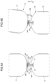
- FIGS. 5 A & 5 B show two electrically powered vehicles for application in the system according to FIG. 1 , which are mutually electrically coupled by means of an exemplary embodiment of an electrically contacting coupling device.
- FIGS. 6 A & 6 B show the coupling device according to FIGS. 5 A and 5 B .
- FIGS. 7 A & 7 B show two electrically powered vehicles for application in the system according to FIG. 1 , which are mutually electrically coupled by means of an exemplary embodiment of an inductive coupling device.
- FIG. 8 shows a flow diagram of a method for the exchange of electrical energy between two moving electrically powered vehicles.
- FIGS. 9 A to 9 C show a coupling element with a telescopic arm, having pneumatic muscles.
- FIGS. 10 A & 10 B show two electrically powered vehicles, which are coupled by means of a coupling device for the transmission of energy, for application in the system according to FIG. 1 and in the method according to FIG. 8 , wherein the coupling device comprises the arm according to FIGS. 9 A to 9 C .
- FIG. 11 shows a cross-section of the arm according to FIGS. 9 A to 10 B .
- FIG. 12 shows two electrically powered vehicles for application in the system according to FIG. 1 and in the method according to FIG. 8 , which are mutually coupled by means of an exemplary embodiment of a coupling device, which is configured for the phototransmission of energy.
- FIG. 13 shows an arrangement of laser beams in the coupling device according to FIG. 12 .
- FIG. 1 shows a system 1 , in which an electrically powered vehicle can be supplied with energy during travel, in order to increase the range of the latter.
- the system 1 comprises a plurality of electrically powered vehicles, also frequently described as electric vehicles, including a first vehicle F 1 and a second vehicle F 2 .
- the vehicles F 1 , F 2 each comprise at least one electrical energy store 10 , as can be seen e.g. with reference to FIG. 2 , which can be supplied with electrical energy and can store electrical energy.
- the energy store is preferably an accumulator. Electrical energy stored in the energy store can be emitted e.g. to an electric motor of the respective vehicle F 1 , F 2 , which is coupled to the wheels of the vehicle, for the electric propulsion of said vehicle.
- both vehicles F 1 , F 2 are passenger cars.
- the system 1 further comprises a central unit Z.
- the central unit Z comprises a communication unit and a data processing unit, specifically a computer.
- the communication unit of the central unit is configured for wireless communication, or is operatively connected to a device for wireless data communication.
- the communication unit of the central unit comprises a mobile radio module or a mobile radio base station.
- the vehicles F 1 , F 2 in the system 1 are autonomously driven vehicles. They can thus travel along a route, without the necessity for a human driver to steer the vehicle F 1 , F 2 .
- each of the vehicles F 1 , F 2 comprises a control unit 11 , which is responsible for steering (see FIG. 2 ).
- the route to be travelled can e.g. be entered in the control unit 11 by a passenger or the control unit 11 receives a predefined route via a communication unit 12 of the respective vehicle F 1 , F 2 .
- the communication unit 12 is configured for wireless data communication e.g. the communication unit comprises a mobile radio module.
- the communication units 12 of the vehicles F 1 , F 2 can communicate with one another and/or with the communication unit of the central unit Z, and specifically exchange information in this manner.
- the central unit Z can communicate predefined routes to the vehicles F 1 , F 2 .
- the vehicles F 1 , F 2 can moreover comprise one or more appropriate environment sensors and/or one or more cameras, which deliver information to the control unit 11 .
- the control unit 11 steers the vehicle F 1 , F 2 along the predefined route, wherein it employs information from the environment sensors and/or the cameras for the safe navigation through traffic.
- the first vehicle F 1 moves along a predefined first route R 1
- the second vehicle moves along a predefined second route R 2 .
- Both routes R 1 , R 2 extend respectively from a starting point to a destination point.
- the routes run along roads S, or along other roadways which are accessible to the vehicles F 1 , F 2 .
- the routes R 1 , R 2 run along schematically represented roads of a city.
- the first and second routes R 1 , R 2 are mutually distinct, and incorporate no overlapping route section.
- the vehicles F 1 , F 2 In order to navigate the first route R 1 through to the destination point, the vehicles F 1 , F 2 require a specific quantity of energy. The exact value of this quantity of energy is dependent upon a number of characteristics including, for example, the course of the route, the actual density of traffic, weather conditions, etc.. For these parameters, estimated values are available, which can be calculated on the basis of map data which are saved in the vehicles F 1 , F 2 and/or in the central unit Z, and/or on the basis of data provided by the vehicles F 1 , F 2 in the system 1 or e.g. by other vehicles. This calculation can be executed by the vehicles F 1 , F 2 in the system 1 , or by the central unit Z.
- a threshold value for the state of charge of the energy store 10 of each vehicle F 1 , F 2 is defined. If the actual state of charge exceeds the threshold value, the vehicle F 1 , F 2 has a surplus of stored energy, and is able to emit energy. If the actual state of charge lies below the threshold value (or a further threshold value), the vehicle F 1 , F 2 has a shortfall of stored energy, and will need to take on energy before reaching its destination point.
- the first electric vehicle F 1 has a surplus of stored energy
- the second vehicle F 2 has a shortfall of energy.
- the second vehicle F 2 would need to incorporate an intermediate stop at a charging station in its second route R 2 , or even alter its route, in order make such an intermediate stop possible. This is wasteful of time, and also potentially of energy. Potentially, the distance to the nearest charging station may even be such that it cannot be reached with the remaining energy or within the associated range, such that it may even be necessary for the vehicle to be towed.
- the vehicles F 1 , F 2 communicate their states of charge to the central unit Z.
- the central unit Z further calculates the threshold values, or also obtains these from the vehicles F 1 , F 2 .
- the vehicles F 1 , F 2 communicate an energy shortfall and/or an energy surplus to the central unit Z.
- the central unit Z calculates an altered first route R 1 ′ and an altered second route R 2 ′, each of which preferably assumes the same starting and destination points as the first or second routes R 1 , R 2 .
- the changed routes R 1 ′, R 2 ′ incorporate a coinciding route section RA. On the coinciding route section RA, the changed routes R 1 ′, R 2 ′ cover the same road(s).
- the changed routes R 1 ′, R 2 ′ incorporate both spatial and temporal information. Temporal information specifies at which point in time a specific point on the changed route R 1 ′, R 2 ′ is to be passed.
- the system 1 can comprise a plurality of vehicles, from which it can select a pair comprised of a first and a second vehicle, the routes of which show exceptionally good potential for mutual matching.
- the altered routes R 1 ′, R 2 ′ are transmitted by the central unit Z to the vehicles F 1 , F 2 .
- the vehicles F 1 , F 2 are steered along the changed routes R 1 ′, R 2 ′.
- On the coinciding route section RA they move in proximity to one another.
- Changing of the routes can be executed such that the two vehicles F 1 , F 2 share the longest possible (common) coinciding route section RA.
- the two vehicles F 1 , F 2 merge into the traffic flow such that, by the start of this coinciding route section RA, they are already driving one behind another.
- the system 1 comprises a coupling device 13 A for the transmission of electrical energy between the vehicles F 1 , F 2 .
- the coupling device 13 A according to FIG. 2 is configured as an inductive coupling device.
- the coupling device 13 A comprises a first coupling element 14 A, which is arranged on the vehicle tail FH of each of the vehicles F 1 , F 2 , and a second coupling element 15 A, which is arranged on the vehicle front FF of each of the vehicles F 1 , F 2 . If a first coupling element 14 A and a second coupling element 15 A are positioned at a distance A from one another which is smaller than a predefined maximum distance (e.g. 2 meters, 1 meter, 50 cm or 20 cm), they can exchange energy by induction.
- each of the coupling elements 14 A, 15 A comprises at least one induction coil.
- the induction coil of the first coupling element 14 A generates an alternating magnetic field.
- this alternating magnetic field generates an alternating current in the induction coil of the second coupling element 15 A which (specifically by the use of a rectifier) is employed for the charging of the energy store 10 of the second vehicle F 2 .
- the coupling device 13 A can execute resonant-inductive coupling. Resonant-inductive coupling enlarges the potential distance between the induction coils by 1 to 2 m.
- the vehicles F 1 , F 2 are positioned one behind another on the coinciding route section RA at a distance A which is smaller than the predefined maximum distance.
- the energy store 10 of the first vehicle F 1 via the coupling device 13 A, delivers electrical energy to the energy store 10 of the second vehicle F 2 .
- the state of charge of the energy store 10 of the second vehicle F 2 is increased accordingly.
- Energy transmission can be executed under stationary conditions (e.g. in congestion or at traffic lights) and/or in motion.
- the second vehicle F 2 is thus charged during travel, and its range is increased. Specifically, if the first vehicle F 1 cannot emit sufficient energy, it is possible to repeat the process with a further vehicle in the system 1 which has an energy surplus.
- one or more of the vehicles F 1 , F 2 can also assume the functions of the central unit Z.
- the first vehicle F 1 is driving ahead of the second vehicle F 2 , and one or more further road users are present between the vehicles F 1 , F 2 .
- the coinciding route section RA comprises a multi-lane carriageway
- the first vehicle F 1 could drive somewhat slower
- the second vehicle F 2 could drive somewhat faster, such that vehicles present between the vehicles F 1 , F 2 either overtake the first vehicle F 1 , or are themselves overtaken by the second vehicle F 2 .
- An overtaking process is thus initiated or induced.
- Initiation of the overtaking process and/or waiting for a turn-off can be established and triggered by communication between the vehicles F 1 , F 2 and/or the intervening road users and/or by communication with the central unit Z.
- the intervening road user can be a third vehicle F 3 in the system 1 , which can communicate with the first and second vehicles F 1 , F 2 and/or with the central unit Z.
- the first vehicle F 1 can be instructed, for a short waiting period (e.g. less than 30 s) to make a stop in a designated stopping place (e.g. a parking space, an entrance, etc.).
- a short waiting period e.g. less than 30 s
- a stop in a designated stopping place e.g. a parking space, an entrance, etc.
- an overtaking of these vehicles might be purchased or requested.
- An intervening vehicle will then provide a gap between itself and the first vehicle F 1 , into which the second vehicle F 2 can overtake.
- a third vehicle F 3 in the system 1 which is situated between the first and second vehicles F 1 , F 2 to transmit electrical energy from the first vehicle F 1 to the second vehicle F 2 .
- the third vehicle F 3 comprises a first and a second coupling element 14 A, 15 A, by means of which it can receive energy from the first vehicle F 1 and can deliver energy to the second vehicle F 2 .
- the third vehicle F 3 functions as a passive transmission partner. This functionality is transferable to a larger number of vehicles, in order to constitute a vehicle train in which one or more of said vehicles are supplied with energy by one or more other vehicle(s).
- one of the plurality of vehicles F 1 , F 2 , F 3 which are electrically coupled by means of the coupling devices 13 A, in this case the first vehicle F 1 , can supply electrical energy to a plurality of the other vehicles F 2 , F 3 .
- FIGS. 4 A and 4 B show a first vehicle F 1 and a second vehicle F 2 in the system 1 according to FIG. 1 , which only differ from the vehicles F 1 , F 2 according to FIG. 2 with respect to their coupling device 13 B.
- the coupling device 13 B comprises a first coupling element 14 B, which is fitted to the first vehicle F 1 , specifically in the example according to FIGS. 4 A and 4 B on the vehicle tail FH.
- the coupling device 13 B further comprises a second coupling element 15 B, which is fitted to the second vehicle F 2 , in the example represented on the vehicle front FF.
- Both coupling elements 14 B, 15 B respectively comprise an induction coil 140 , 152 .
- the induction coils 140 , 152 can be mutually inductively coupled for the transmission of electrical energy. Coupling over the shortest possible distance is particularly efficient.
- the first coupling element 14 B comprises a coil carrier 141 , to which the induction coil 140 is attached.
- the coil carrier 141 is attached to the vehicle tail FH of the first vehicle F 1 , e.g. onto or in the fender.
- the coil carrier 141 is constituted, for example, in the form of a block or a pad of rubber or similar.
- the second coupling element 15 B comprises an arm 150 .
- the arm 150 is moveable relative to the second vehicle F 2 .
- the arm 150 is configured for longitudinal displacement along the longitudinal axis of the vehicle (which extends from the vehicle tail FH to the vehicle front FF).
- the arm 150 can thus be retracted and deployed in the direction of travel (in relation to a straight driving trajectory). In this manner, the arm 150 can offset and bridge a distance A between the vehicles F 1 , F 2 which varies during the travel of said vehicles F 1 , F 2 , in order to permit the achievement of the shortest possible distance between the induction coils 140 , 152 .
- a coil carrier 153 is arranged on the end of the arm 150 which is averted from the second vehicle F 2 .
- the induction coil 152 of the second coupling element 15 B is attached to the coil carrier 153 .
- the coil carrier 153 is mounted on the arm 150 so as to be pivotable about an articulated joint 151 . If the second vehicle F 2 is situated on a flat road, the pivoting axis of the articulated joint 151 is essentially oriented perpendicularly to the road. By means of the pivoting facility, the two induction coils 140 , 152 can continue to be mutually oriented even in a curved driving trajectory (see FIG. 4 B ), in order to permit the achievement of the maximum coupling efficiency.
- the arm 150 further permits the interception of any impacts due to components such as shock-absorbers or yielding articulated joints, without the measurement of distance and any subsequent adjustment (also described as “passive compliance”).
- the coupling device 13 B further comprises a sensor 16 , e.g. in the form of a force, acceleration or distance sensor, which is configured to measure a force and/or an acceleration acting on the arm 150 , or to measure the distance A between the vehicles F 1 , F 2 .
- a sensor 16 e.g. in the form of a force, acceleration or distance sensor, which is configured to measure a force and/or an acceleration acting on the arm 150 , or to measure the distance A between the vehicles F 1 , F 2 .
- the coupling device 13 B also comprises a drive system 17 , in order to move the arm 150 relatively to the second vehicle F 2 and/or to pivot the coil carrier 153 about the articulated joint 151 .
- the arm 150 and/or the coil carrier 153 can be moved by means of the drive system 17 , for the purposes of the active orientation of the induction coil 152 of the second coupling element 15 B vis-à-vis the induction coil 140 of the first coupling element 14 B (also described as “active compliance”).
- the drive system 17 can be controlled in accordance with measured values from the sensor 16 .
- the coupling device 13 B further comprises an interlocking mechanism, for the mutual mechanical interlocking of the two coil carriers 141 , 153 , e.g. in a positive locking and/or non-positive locking manner.
- the interlocking mechanism can be controlled in accordance with measured values from the sensor 16 , e.g. opened i.e. unlocked in the event of an overshoot of a predefined force.
- the interlocking mechanism comprises a hook 159 on the second coupling element 15 B which, for the closure of the interlocking mechanism, engages with a counter-bearing 146 on the first coupling element 14 B.
- FIGS. 5 A and 5 B show a first vehicle F 1 and a second vehicle F 2 in the system 1 according to FIG. 1 , which only differ from the vehicles F 1 , F 2 according to FIG. 2 with respect to their coupling device 13 C.
- the coupling device 13 C permits coupling by direct electrical contact.
- the coupling device 13 C comprises a first coupling element 14 C, which is fitted to the first vehicle F 1 , specifically in the example according to FIGS. 5 A and 5 B on the vehicle tail FH.
- the coupling device 13 C further comprises a second coupling element 15 C, which is fitted to the second vehicle F 2 , in the example represented on the vehicle front FF.
- Both coupling elements 14 C, 15 C respectively comprise an electrical contact.
- the electrical contacts of the coupling elements 14 C, 15 C are brought into mutual contact. Direct electrical contact of this type can exhibit very low losses in the transmission of electrical energy.
- the coupling device 13 C comprises a moveable arm 150 , a sensor 16 and a drive system 17 , and is capable of longitudinal displacement, as per the coupling device 13 B according to FIGS. 4 A and 4 B .
- the first coupling element 14 C comprises a coupling socket 142 (or a socket in general) and the second coupling element 15 C comprises a coupling ball 155 (or a plug-in element in general).
- the coupling ball 155 can engage with the coupling socket 142 in a contact-connected manner, by means of the movable arm 150 .
- the coupling socket 142 partially encloses the coupling ball 155 .
- the coupling ball in combination with the arm 150 , is pivotable in the coupling socket 142 over a specific angular range. This permits a tolerance margin in the relative orientations of the vehicles F 1 , F 2 to one another, for example on curves or on hills.
- the electrical contacts 143 , 144 of the coupling socket 142 and the electrical contacts 156 , 157 of the coupling ball 155 extend, in cross-section, over a specific angular range (e.g.
- the arm 150 If the arm 150 is operated with passive compliance, it can be deployed from the second vehicle F 2 and, then, by means of vehicle movements, inserted into the socket, and retained therein.
- the arm 150 can passively offset a variation in the distance A between the vehicles F 1 , F 2 , and specifically compensate a convergence or divergence of the vehicles F 1 , F 2 .
- a spring mechanism can ensure that contact with the first vehicle F 1 is maintained, even where the distance A increases.
- the arm 150 can additionally move independently in the socket, with no adjustment in the vehicle position and, if required, can execute the tracking of mutual changes in the relative position of the vehicles F 1 , F 2 .
- the coupling device 13 C further comprises a magnetic interlocking mechanism (alternatively or additionally, it might also incorporate a mechanical interlocking mechanism, as per the coupling device 13 B according to FIGS. 4 A, 4 B ).
- a magnetic interlocking mechanism alternatively or additionally, it might also incorporate a mechanical interlocking mechanism, as per the coupling device 13 B according to FIGS. 4 A, 4 B ).
- an electromagnet 158 , 145 is arranged on the coupling ball 155 and/or the coupling socket 142 , by the activation of which the coupling elements 14 C, 15 C are mutually magnetically interlocked.
- the coupling socket 142 can incorporate an array of carbon brushes. These are compressed against the coupling ball 155 e.g. by means of springs, such that electrical contact is consistently maintained.
- FIGS. 7 A and 7 B show a first vehicle F 1 and a second vehicle F 2 for the system 1 according to FIG. 1 , which only differ from the vehicles F 1 , F 2 according to FIG. 2 with respect to their coupling device 13 D.
- the coupling device 13 D permits inductive coupling.
- the coupling device 13 D comprises a first coupling element 14 D, which is fitted to the first vehicle F 1 , specifically in the example according to FIGS. 7 A and 7 B on the vehicle tail FH.
- the coupling device 13 D also comprises a second coupling element 15 D, which is fitted to the second vehicle F 2 , in the example represented on the vehicle front FF.
- the vehicle front FF of the second vehicle F 2 and the vehicle tail FH of the first vehicle F 1 assume complementary shapes.
- the vehicle front FF of the second vehicle F 2 is configured to a convex design.
- the vehicle tail FH of the first vehicle F 1 is configured to a concave design.
- a plurality of induction coils 152 , 140 of the coupling device 13 D are arranged.
- Induction coils 152 of the coupling element 15 D of the second vehicle F 2 constitute a convex arrangement.
- Induction coils 140 of the coupling element of the first vehicle F 1 constitute a matching concave arrangement.
- the induction coils 140 , 152 are arranged along correspondingly shaped fenders of the vehicles F 1 , F 2 , specifically along the full width of the fenders.
- a distance which exceeds the range of the arm 150 prevents any direct electrical contact-connection of the coupling device 13 C according to FIGS. 5 A- 6 B .
- the mutual distance A of the vehicles F 1 , F 2 from one another should be smaller than a predefined maximum distance Amax and greater than a predefined minimum distance Amin. This is permitted by the following process steps, illustrated in FIG. 8 :
- step S 200 the electrically powered first vehicle F 1 is provided, which comprises the electrical energy store 10 , wherein the first vehicle F 1 can be electrically powered by means of energy stored therein, and wherein the energy store 10 can emit electrical energy, and specifically features an energy surplus.
- step S 201 the electrically powered second vehicle F 2 is provided, which comprises the electrical energy store 10 , wherein the second vehicle F 2 can be electrically powered by means of the energy stored therein, wherein the energy store 10 can receive electrical energy, and specifically features a shortfall of energy.
- step S 202 the first vehicle F 1 is steered along the first route R 1 and the second vehicle F 2 is steered along the second route R 2 , such that both vehicles F 1 , F 2 , at least along the coinciding route section RA, move relative to one another at the distance A.
- step S 203 information with respect to a driving state of at least one of the two vehicles F 1 , F 2 is transmitted between the first and the second vehicle F 1 , F 2 .
- This is achieved e.g. by means of direct communication between the vehicles F 1 , F 2 and/or by means of communication via the central unit Z.
- a prediction of the driving state or the driving behavior of one of the two, or of both vehicles F 1 , F 2 is calculated.
- step S 204 the distance A between the vehicles F 1 , F 2 , due to the steering of the first and/or the second vehicle F 1 , F 2 on the basis of the information thus transmitted, is adjusted or set such that the distance A during the movement of both vehicles F 1 , F 2 along the coinciding route section RA is greater than the predefined minimum distance Amin and smaller than the predefined maximum distance Amax.
- step S 106 electrical energy is then transmitted from the energy store 10 of the first vehicle F 1 , by means of the respective coupling device 13 A- 13 D, to the energy store 10 of the second vehicle F 2 , while the distance A during the movement of both vehicles F 1 , F 2 along the coinciding route section RA is greater than the minimum distance Amin and smaller than the maximum distance Amax.
- one of the vehicles can measure its distance to the other vehicle and, in accordance with the results of this measurement, can adjust its relative position to the other vehicle. Accordingly, no exchange of information is required, and step S 203 is optional.
- a plurality of latencies are then cumulatively combined, specifically the following: a sensor latency, a cognitive latency (pending the initiation of a change in behavior of the vehicle) and an engine latency (further to which the change in behavior is detectable) of the other vehicle, together with a sensor latency, a cognitive latency and an engine latency of the vehicle which adjusts the distance.
- the first vehicle F 1 e.g. can transmit actual states, e.g. with respect to its speed and/or acceleration to the second vehicle F 2 , thereby obviating the measurement thereof by the latter, and the associated latency.
- the second vehicle F 2 delivers current or future control commands (e.g. target values for a speed and/or acceleration) for the second vehicle F 2 .
- the second vehicle F 2 by reference to these control commands and by means of a predictive model, can calculate an anticipated actual state of the first vehicle F 1 .
- Input parameters of the predictive model include e.g. a speed and an acceleration, and additionally, optionally, a gradient of the carriageway and/or wind and weather conditions.
- the first vehicle F 1 can execute the delayed implementation of its notified control commands by a predefined or predefinable latency period, in order to further improve the synchronization of the vehicles F 1 , F 2 .
- the first vehicle F 1 calculates a prediction of future control commands (on its own account, e.g. for the coming seconds). These predicted control commands can be transmitted by the first vehicle F 1 to the second vehicle F 2 . By reference to these predicted control commands, the second vehicle F 2 can minimize fluctuations in the vehicle distance.
- the first vehicle F 1 for each time increment, refreshes a model of its future actions (specially control commands).
- This model might (concurrently) incorporate a plurality of different scenarios and a probability of the execution thereof (e.g. an overtaking maneuver, a braking maneuver or a change of lane, by way of corresponding movement trajectories, inclusive of speeds and accelerations, etc., with their respective probability over time).
- the second vehicle F 2 on the basis of its own sensor data or sensor data relayed by the first vehicle F 1 , and by the application of the model of the first vehicle F 1 , might calculate a prediction of which predicted control commands are to be transmitted by the first vehicle F 1 to the second vehicle F 2 .
- the second vehicle F 2 can thus adjust the distance A to the first vehicle F 1 by predicting the movement of the first vehicle F 1 .
- the adjustment of the second vehicle F 2 is executed e.g. by means of the communication by the first vehicle F 1 to the second vehicle of a real-time prediction of its driving behavior or driving state.
- This can include various information, specifically a hierarchy of information, such as e.g. a prediction of vehicle acceleration (positive or negative), for example in the respective next tenth of a second, a planned change of direction, e.g. over the next few seconds, and/or sensor data or road characteristics which permit the prediction of vehicle behavior or a drive state, such as e.g. potholes which are logged in a memory of one of the vehicles F 1 , F 2 , or of the central unit Z.
- a hierarchy of information such as e.g. a prediction of vehicle acceleration (positive or negative), for example in the respective next tenth of a second, a planned change of direction, e.g. over the
- the first vehicle F 1 can adjust the distance A to the second vehicle F 2 , wherein it controls the second vehicle F 2 .
- the first vehicle F 1 is in possession of the relevant information required for the control of the vehicle train F 1 , F 2 .
- Driving control of the second vehicle F 2 can thus be surrendered to the first vehicle F 1 .
- the second vehicle F 2 can here receive and directly implement commands from the first vehicle F 1 (specifically by way of the control of an electric motor, a brake and/or a steering angle).
- the first vehicle F 1 delays its own control commands, in order to compensate any transmission latency of the commands to the second vehicle F 2 .
- the first vehicle F 1 in its control of the vehicle train F 1 , F 2 , can predict the behavior of the second vehicle F 2 by the employment of a previously communicated vehicle model.
- This vehicle model incorporates e.g. characteristic variables which permit the calculation of the behavior of the second vehicle F 2 , in response to given control commands, in a number of future time increments.
- the vehicle model can be transmitted by the second vehicle F 2 to the first vehicle F 1 (e.g. in the form of a handshake).
- the vehicle model can predict engine values with reference to corresponding anticipated and measured actual values and, optionally, can be inversely employed by the first vehicle F 1 (tailoring target behavior to engine values), in order to calculate engine values for the second vehicle F 2 which will result in behavior that the first vehicle F 1 anticipates on its own account.
- the second vehicle F 2 can provide a dedicated interface, via which the first vehicle F 1 communicates target values for the driving behavior or driving state of the second vehicle F 2 (at a future time point) to the second vehicle F 2 .
- the second vehicle F 2 can then employ a dedicated control loop (and optionally a model of its own future driving behavior or driving state) in order to achieve the target specifications of the first vehicle F 1 .
- both vehicles F 1 , F 2 undertake the mutual exchange of information.
- the vehicles F 1 , F 2 can share e.g. a schedule of (their own respective) future driving behavior or driving state, in order to improve their respective prediction of the driving behavior or driving state of one or both vehicles F 1 , F 2 .
- the distance can be adjusted without the exchange of information between the vehicles F 1 , F 2 .
- the second vehicle F 2 Independently of the first vehicle F 1 , the second vehicle F 2 can measure its distance and its relative position to the first vehicle F 1 , and can adjust its acceleration such that the distance remains constant.
- this can require a very rapid implementation of control commands and correspondingly necessitate high-speed sensors, i.e. having a small temporal latency and a high temporal sampling rate.
- Both vehicles F 1 , F 2 can also measure and adjust the distance relative to one another.
- a vehicle If a vehicle identifies a shortfall of energy, it can submit a request to the central unit Z. Alternatively or additionally, the central unit Z monitors the states of charge of a plurality of vehicles and identifies, optionally in consideration of the respective route plan, a shortfall or surplus of stored energy. The system 1 then executes the following steps.
- an electrically powered first vehicle F 1 is identified and provided, which comprises an electrical energy store 10 , wherein the first vehicle F 1 can be electrically powered by means of energy stored therein, and wherein the energy store 10 can emit electrical energy (specifically features an energy surplus), and wherein the first vehicle F 1 is currently moving, or is subsequently to be moved along a first route R 1 , e.g. by the programing of a navigation system.
- a second electrically powered vehicle F 2 is identified and provided. This is, for example, the vehicle which has submitted the request to the central unit Z.
- the second vehicle comprises an electrical energy store 10 , wherein the second vehicle F 2 can be electrically powered by means of energy stored therein, and wherein the energy store 10 can receive electrical energy (and specifically features a shortfall of energy), and wherein the second vehicle F 2 is moving, or is to be moved along a second route R 2 .
- step S 101 can also be executed prior to step S 100 .
- a first vehicle F 1 can then be identified (e.g. selected from a large number of potential first vehicles) and provided which, e.g. assumes a similar current location, a similar course of the first route R 1 and/or the energy store of which 10 has a sufficient state of charge.
- the second route R 2 is changed such that both routes R 1 , R 2 or, if one or both routes have been changed, the changed route(s) R 1 ′, R 2 ′ at least coincide along a route section RA or along an extended route section.
- such vehicles can be identified in steps S 100 , S 101 , and provided as first and second vehicles F 1 , F 2 which already assume routes R 1 , R 2 having a coinciding route section RA.
- step S 104 the first vehicle F 1 is steered along the first route R 1 or, if the latter has been changed, along the changed first route R 1 ′, and the second vehicle F 2 is steered along the second route R 2 or, if this has been changed, along the changed second route R 2 ′ such that, specifically in each case, the two vehicles F 1 , F 2 move along the coinciding route section RA at a distance A from one another which is smaller than a predefined maximum distance Amax.
- the maximum distance Amax is e.g. 50 cm, 1 m, 2 m or 5 m.
- vehicles situated between the vehicles F 1 , F 2 are removed from the interspace (step S 105 ).
- step S 106 electrical energy is move from the energy store 10 of the first vehicle F 1 on F 1 , F 2 moving along the coinciding route section RA and/or situated on the coinciding route section RA.
- this is executed via one or more vehicles F 3 which are situated between the first and the second vehicle F 1 , F 2 .
- the method can proceed from step S 104 or step S 105 to step S 203 .
- Steps S 203 , S 204 , S 106 and/or S 104 can be executed simultaneously.
- the system 1 comprises means for executing the process steps illustrated in FIG. 8 , specifically at least the first and second vehicle F 1 , F 2 , at least one of the coupling devices 13 A- 13 D described herein, and/or the central unit Z.
- both vehicles can comprise both a first coupling element 14 A- 14 D and a second coupling element 15 A- 15 D.
- the arrangement of the first coupling element 14 A- 14 D and of the second coupling element 15 A- 15 D on the first and second vehicle F 1 , F 2 can also be interchanged vis-à-vis the arrangements illustrated in FIGS. 2 to 7 B .
- first and the second vehicles F 1 , F 2 are essentially of an identical design.
- FIGS. 9 A to 9 C show an exemplary embodiment of a (second) coupling element 15 E of a coupling device for a vehicle F 2 , e.g. a vehicle in the system according to FIG. 1 and/or for employment in the method according to FIG. 8 .
- the coupling element 15 E is arranged on the vehicle front FF (specifically on the fender) of the vehicle F 2 .
- the coupling element 15 E comprises a telescopic arm 150 ′.
- the telescopic arm 150 ′ comprises a coupling head 185 .
- the coupling head 185 is configured for the transmission of energy.
- the coupling head 185 is configured as per the coil carrier 153 according to FIGS. 4 A and 4 B .
- the coupling head 185 is fitted to the end of a cable 180 .
- the cable 180 is an electric cable 180 .
- the cable 180 can be wound onto a cable reel 182 and paid-out from said cable reel 182 .
- the cable reel 182 optionally comprises a motor, for the optional wind-up or pay-out of the cable.
- Guide rollers 184 on the fender of the vehicle F 2 guide the cable 180 .
- the guide rollers 184 are motorized, and are specifically configured for the deployment of the cable 180 (and optionally, additionally, for the retraction thereof).
- FIG. 9 A represents a state in with the cable 180 , together with the coupling head 185 , is retracted
- FIGS. 9 B and 9 C respectively represent a state in which the cable 180 , together with the coupling head 185 , is at least partially deployed.
- the arm 150 ′ further comprises pneumatic muscles 181 .
- the pneumatic muscles 181 are inflatable by means of a compressor 183 , e.g. using air or another fluid.
- the compressor 183 is fitted to the vehicle F 2 .
- the pneumatic muscles 181 are deflatable by means of the compressor 183 and/or additional controllable valves, i.e. air (or fluid in general) can be released from the pneumatic muscles 181 .
- the pneumatic muscles 181 are arranged longitudinally and parallel to the cable 180 . Specifically, the pneumatic muscles 181 are attached to the cable 180 . In the example according to FIG. 11 , four pneumatic muscles 181 are arranged around the cable 180 , wherein another number is also conceivable.
- the arm 150 ′ can comprise at least one, specifically two or more pneumatic muscles 181 . If the arm 150 ′ comprises only one pneumatic muscle 181 , this is fitted e.g. on the upper side of the cable 180 (in relation to a vehicle which is positioned on a flat base surface.
- An uninflated pneumatic muscle 181 is flexible, e.g. of similar flexibility to the cable 180 .
- the cable 180 can then be wound onto the cable reel 182 in combination with the pneumatic muscles 181 .
- the pneumatic muscles 181 Prior to winding-on, or during winding-on, the pneumatic muscles 181 (insofar as they are inflated) are evacuated. Given that, depending upon the configuration of the pneumatic muscles 181 , this can require a specific time interval, the cable reel 182 can be configured such that it can tension the wound-on arm 150 ′ (on the inner side).
- an inflated pneumatic muscle 181 is essentially rigid. Specifically, an inflated pneumatic muscle 181 is less flexible than in the uninflated state. According to FIG. 9 B , all the pneumatic muscles 181 on the section of cable 180 which is deployed from the fender are inflated. The inflated pneumatic muscles 181 hold the cable 180 straight, e.g. in order to couple the coupling head 185 with a coupling head on another vehicle.
- a pneumatic muscle 181 is shorter than in the uninflated state.
- each pneumatic muscle 181 comprises a (flexible) hose, which contracts under pressure.
- the hose is enclosed e.g. in fibers, which are arranged in a rhomboid-pattern weave.
- a pneumatic muscle comprises one such enclosed hose or, alternatively, a plurality of such enclosed hoses (corresponding to biological muscle fibers).
- the cable 180 will be curved, c.f. FIG. 9 c , wherein the pneumatic muscle 181 represented on the right-hand side of the image is inflated, but that arranged opposite is not.
- the arm 150 ′ comprises a plurality of pneumatic muscles 181 , which are arranged one behind another along the longitudinal extension of the cable 180 .
- the cable 180 can thus be curved e.g. into an S-shape. It can provided that pneumatic muscles 181 are arranged along the entire deployable length of the cable 180 .
- FIGS. 10 A and 10 B show the vehicle F 2 according to FIGS. 9 A to 9 C as a second vehicle F 2 , together with a first vehicle F 1 which is coupled thereto by means of the coupling device 13 E for the transmission of energy.
- the coupling element 15 E can be equipped with sensors, and/or can establish the relative position of the first vehicle F 1 with respect to to the second vehicle F 2 and, in accordance therewith, can actuate at least one pneumatic muscle. This can be executed such that the coupling head 185 is oriented toward coupling head 185 of the other vehicle F 1 .
- the first and/or the second vehicle F 1 , F 2 are steered such that the coupling heads 185 are oriented in relation to one another. Both coupling heads 185 are then e.g. magnetically mutually interlocked.
- one or more pneumatic muscles 181 can be replaced by a static antagonist, e.g. in the form of a flexible metal strip, which is optionally pre-tensioned in one direction.
- a static antagonist e.g. in the form of a flexible metal strip, which is optionally pre-tensioned in one direction.
- one pneumatic muscle 181 for example, with respect to the cable 180 , is arranged in opposition to a static antagonist.
- Coupling of the coupling heads 185 by means of the telescopic arm 150 ′ can be executed e.g. with the vehicles F 1 , F 2 at a standstill (e.g. at a red light) or, alternatively, during travel which, to this end, is optionally limited to a predefined maximum speed.
- a distance is thus set between the vehicles F 1 , F 2 , which can be bridged by the arm 150 ′, e.g. 2 m.
- the pneumatic muscles 181 can be released after the coupling of the coupling heads 185 .
- the arm 150 ′ is flexible, and permits a degree of relative movement between the vehicles F 1 , F 2 (c.f. specifically FIG. 10 B ).
- the cable 180 can optionally be capable of being paid-out further after coupling, e.g. for the provision of a greater safety distance.
- the cable reel 182 is pre-tensioned, and prevents any sagging of the cable 180 .
- the coupling heads 185 become detached, e.g. as a result of an excessive relative movement between the two vehicles F 1 , F 2 , this is detected by the second vehicle F 2 (e.g. by the control unit 11 thereof).
- the compressor 183 is actuated, such that the pneumatic muscles 181 are inflated and the cable 180 is wound-in (wherein the pneumatic muscles 181 are again relaxed).
- the compressor 183 and the pneumatic muscles 181 and/or the cable reel 182 can function as a drive system, which is configured to move the arm 150 ′ in accordance with the distance between the two vehicles F 1 , F 2 and/or the forces and/or accelerations acting on the arm 150 ′.
- FIG. 12 shows two vehicles F 1 , F 2 with a coupling device 13 F, which is configured to transmit energy by means of electromagnetic radiation, specifically light (specifically in the infrared or ultraviolet spectrum, although other wavelengths, in the visible spectrum, are also conceivable).
- electromagnetic radiation specifically light (specifically in the infrared or ultraviolet spectrum, although other wavelengths, in the visible spectrum, are also conceivable).
- the first vehicle F 1 comprises one or more photovoltaic cells 186
- the second vehicle F 2 comprises one or more lasers 187 for the transmission of energy.
- the orientation of the laser beam is controllable in accordance with the position of the two vehicles F 1 , F 2 relative to one another.
- the laser 187 is aimed at the photovoltaic cell 186 . If the mutual distance between the two vehicles F 1 , F 2 exceeds a predefined maximum value, or the photovoltaic cell 186 is lost from the field of vision of the laser 187 , the laser 187 is switched off.
- the laser 187 is a high-power laser.
- the second vehicle F 2 comprises one or more further lasers 189 , which can have a lower power than the high-power laser 187 .
- the lasers 189 emit e.g. a ring of laser beams which are essentially parallel to the laser beam of the high-power laser 187 .
- Reflectors 188 are arranged around the photoelectric cell 186 (e.g. each in the form of a retroreflector).
- a photoreceptor e.g. a photodiode, a camera or similar is provided which detects light (emitted by the respective laser 189 ) and reflected by one of the reflectors 188 .
- the laser beams L 2 of the laser 189 are arranged in accordance with a ring around the high-power laser beam L 1 of the high-power laser 187 —see FIG. 13 . If one or more of the laser beams L 2 in the ring is obstructed, e.g. by an animal which moves between the vehicles F 1 , F 2 , the photoreceptor of the respective laser 189 registers that the laser beam L 2 is no longer being reflected. Thereafter, the respective photoreceptor can transmit a signal to the high-power laser 187 , which initiates a switch-off of said high-power laser 187 . As the photoreceptors respond substantially more rapidly than the movement of the animal reaches the high-power laser beam L 1 , it is possible to switch off the high-power laser beam L 1 sufficiently rapidly, such that the high-power laser beam L 1 does not engage with the animal.
- the laser 189 and the reflectors 188 constitute a plurality of light barriers which are arranged around the high-power laser beam L 1 , wherein other types of light barrier arranged around the high-power laser beam L 1 are also conceivable.
- the light barriers 188 , 189 are encoded, e.g. according to wavelength and/or wherein radiation from the light barriers assumes differing pulse characteristics. It can be provided that the high-power laser 187 is switched off if at least one of the encoded light beams does not engage with the respectively associated receiver. It can thus be prevented that the high-power laser 187 is directed to a location other than the photovoltaic cell 186 , e.g. in the event of relative movements between the vehicles F 1 , F 2 . Moreover, information can be transmitted by means of radiation from the light barriers 188 , 189 , e.g. concerning a driving state.
Landscapes
- Engineering & Computer Science (AREA)
- Mechanical Engineering (AREA)
- Power Engineering (AREA)
- Transportation (AREA)
- Remote Sensing (AREA)
- Radar, Positioning & Navigation (AREA)
- Physics & Mathematics (AREA)
- General Physics & Mathematics (AREA)
- Automation & Control Theory (AREA)
- Aviation & Aerospace Engineering (AREA)
- Life Sciences & Earth Sciences (AREA)
- Sustainable Energy (AREA)
- Sustainable Development (AREA)
- Computer Networks & Wireless Communication (AREA)
- Business, Economics & Management (AREA)
- Health & Medical Sciences (AREA)
- Artificial Intelligence (AREA)
- Evolutionary Computation (AREA)
- Game Theory and Decision Science (AREA)
- Medical Informatics (AREA)
- Electric Propulsion And Braking For Vehicles (AREA)
Abstract
Description
-
- 1 System
- 10 Energy store
- 11 Control unit
- 12 Communication unit
- 13A-13F Coupling device
- 14A-14F First coupling element
- 140 Induction coil
- 141 Coil carrier
- 142 Coupling socket
- 143, 144 Electrical contact
- 145 Electromagnet
- 146 Counter-bearing
- 15A-15F Second coupling element
- 150, 150′ Arm
- 151 Articulated joint
- 152 Induction coil
- 153 Coil carrier
- 154 Articulated joint
- 155 Coupling ball
- 156, 157 Electrical contact
- 158 Electromagnet
- 159 Hook
- 16 Sensor
- 17 Drive system
- 180 Cable
- 181 Pneumatic muscle
- 182 Cable reel
- 183 Compressor
- 184 Guide roller
- 185 Coupling head
- 186 Photovoltaic cell
- 187 Laser
- 188 Reflector
- 189 Laser
- A Distance
- Amin Minimum distance
- Amax Maximum distance
- F1, F2, F3 Vehicle
- FF Vehicle front
- FH Vehicle tail
- L1 High-power laser beam
- L2 Laser beam
- R1, R2 Route
- R1′, R2′ Changed route
- RA Route section
- S Carriageway
- Z Central unit
Claims (19)
Applications Claiming Priority (3)
| Application Number | Priority Date | Filing Date | Title |
|---|---|---|---|
| DE102017207926.6 | 2017-05-10 | ||
| DE102017207926.6A DE102017207926A1 (en) | 2017-05-10 | 2017-05-10 | Methods and systems for energy exchange between vehicles |
| PCT/EP2018/062082 WO2018206684A1 (en) | 2017-05-10 | 2018-05-09 | Method and systems for energy exchange between vehicles |
Publications (2)
| Publication Number | Publication Date |
|---|---|
| US20230182599A1 US20230182599A1 (en) | 2023-06-15 |
| US12054063B2 true US12054063B2 (en) | 2024-08-06 |
Family
ID=62196540
Family Applications (1)
| Application Number | Title | Priority Date | Filing Date |
|---|---|---|---|
| US16/612,302 Active 2041-07-07 US12054063B2 (en) | 2017-05-10 | 2018-05-09 | Method and systems for energy exchange between vehicles |
Country Status (4)
| Country | Link |
|---|---|
| US (1) | US12054063B2 (en) |
| EP (1) | EP3621845B1 (en) |
| DE (1) | DE102017207926A1 (en) |
| WO (1) | WO2018206684A1 (en) |
Families Citing this family (18)
| Publication number | Priority date | Publication date | Assignee | Title |
|---|---|---|---|---|
| US10933767B2 (en) * | 2019-01-04 | 2021-03-02 | Hyundai Motor Company | Electric vehicle energy sharing marketplace |
| DE102019200505A1 (en) * | 2019-01-16 | 2020-07-16 | Audi Ag | Connection module for the electrical connection of two motor vehicles for an electrical energy exchange as well as motor vehicle and vehicle system |
| CN111457931B (en) * | 2019-01-21 | 2021-09-24 | 广州汽车集团股份有限公司 | Local path replanning control method, device, system and storage medium for autonomous vehicle |
| DE102019207449A1 (en) * | 2019-05-21 | 2020-11-26 | Volkswagen Aktiengesellschaft | Method for charging a battery of an electrically powered vehicle and electrically powered vehicle |
| US11485251B2 (en) | 2019-07-09 | 2022-11-01 | Mercedes-Benz Group AG | Vehicle-based charging system for electric vehicles |
| DE102019211494A1 (en) * | 2019-08-01 | 2021-02-04 | Audi Ag | System for supplying a motor vehicle and motor vehicle having an energy storage unit |
| US20210056854A1 (en) * | 2019-08-23 | 2021-02-25 | Toyota Motor Engineering & Manufacturing North America, Inc. | Hierarchical ai assisted safe and efficient platooning |
| EP3813226B1 (en) * | 2019-10-22 | 2022-07-06 | Ningbo Geely Automobile Research & Development Co. Ltd. | A vehicle module for transporting at least one person and a vehicle assembly |
| EP3936374A1 (en) * | 2020-07-10 | 2022-01-12 | Volvo Truck Corporation | A vehicle system for a subject vehicle driving in a vehicle formation with at least one lead vehicle |
| US11912151B2 (en) | 2020-07-31 | 2024-02-27 | Robert Bosch Gmbh | Reconfigurable electric vehicle chassis |
| KR20230078345A (en) * | 2021-11-26 | 2023-06-02 | 현대모비스 주식회사 | Method of configuring lateral wireless charging chain for electric vehicle and apparatus and system therefor |
| KR20230078346A (en) * | 2021-11-26 | 2023-06-02 | 현대모비스 주식회사 | Method of configuring longitudinal wireless charging chain for electric vehicle and apparatus and system therefor |
| WO2023161596A1 (en) * | 2022-02-25 | 2023-08-31 | Richmond Design And Marketing | Powering and controlling or monitoring of vehicles |
| DE102022204426A1 (en) | 2022-05-05 | 2023-11-09 | Zf Friedrichshafen Ag | System and computer-implemented method for platooning two or more vehicles |
| US20240118096A1 (en) * | 2022-10-07 | 2024-04-11 | Hitachi, Ltd. | Localization and path planning of electric systems during dynamic charging |
| US20240294220A1 (en) * | 2023-03-01 | 2024-09-05 | Sanctuary Cognitive Systems Corporation | Systems, devices, and methods for a mobile robot system |
| DE102023117527A1 (en) | 2023-07-03 | 2025-01-09 | Ford Global Technologies, Llc | charging device for a vehicle and vehicle |
| CN120756481B (en) * | 2025-08-14 | 2025-11-21 | 重庆长安汽车股份有限公司 | Vehicle lane changing control methods, devices, equipment and media |
Citations (27)
| Publication number | Priority date | Publication date | Assignee | Title |
|---|---|---|---|---|
| DE4240989C2 (en) | 1992-12-05 | 1997-02-06 | Opel Adam Ag | Floor conveyor |
| JP2001236530A (en) * | 2000-02-23 | 2001-08-31 | Nec Corp | Tool collection system and road side equipment to be used therefor |
| US7113108B1 (en) * | 2002-04-09 | 2006-09-26 | California Institute Of Technology | Emergency vehicle control system traffic loop preemption |
| DE102005052038A1 (en) * | 2005-10-31 | 2007-05-03 | Robert Bosch Gmbh | Movement device for moving tool element of tool device, has drive which is a pneumatic or hydraulic muscle |
| US20090176457A1 (en) * | 2008-01-04 | 2009-07-09 | Christensen James J | Apparatus and method for communicating with moving receivers |
| JP2010035333A (en) | 2008-07-29 | 2010-02-12 | Fujitsu Ltd | Mobile charging device and mobile charging method |
| US20130076296A1 (en) * | 2010-05-31 | 2013-03-28 | Toyota Jidosha Kabushiki Kaisha | Charging apparatus |
| DE102012216980A1 (en) * | 2011-09-26 | 2013-04-11 | GM Global Technology Operations LLC (n. d. Ges. d. Staates Delaware) | Robotic charging station for charging battery of electric vehicle, has end effector which includes electrical contacts configured to couple with receptacle disposed on electric vehicle |
| JP2013070514A (en) * | 2011-09-22 | 2013-04-18 | Nippon Soken Inc | Electric vehicle and power transmission system |
| CN103262584A (en) * | 2010-12-10 | 2013-08-21 | 奥迪股份公司 | Method for wireless communication between a motor vehicle and at least one other communication partner and motor vehicle |
| DE102012214750A1 (en) | 2012-05-25 | 2013-11-28 | Siemens Aktiengesellschaft | System for supplying electrical power to passenger car during driving on driving route, has coupling device, where power supplied into charging vehicle is transferred to electric vehicle for charging energy storage by coupling device |
| US8649966B2 (en) * | 2010-09-30 | 2014-02-11 | Honda Motor Co., Ltd | Drive support system |
| US20140089064A1 (en) | 2012-09-24 | 2014-03-27 | Elwha Llc | Systems and methods for transferring electrical energy between vehicles |
| US20140188318A1 (en) | 2012-12-28 | 2014-07-03 | International Business Machines Corporation | Managing inter-vehicular battery charging transactions |
| WO2014134551A1 (en) * | 2013-02-28 | 2014-09-04 | Naztec, Inc. | Wireless vehicle detector aggregator and interface to controller and associated methods |
| US20150336677A1 (en) * | 2012-12-21 | 2015-11-26 | European Aeronautic Defence And Space Company Eads France | In-flight refuelling device for electric storage system and aircraft equipped with such a device |
| US20160129793A1 (en) | 2014-11-11 | 2016-05-12 | Empire Technology Development Llc | Wireless vehicle energy sharing |
| US9381818B2 (en) * | 2012-09-28 | 2016-07-05 | Siemens Aktiengesellschaft | Non-track-bound vehicle |
| WO2016156383A1 (en) | 2015-03-31 | 2016-10-06 | Bvb Innovate Gmbh | Use of an autonomous range extender vehicle and autonomous range extender vehicle |
| CN106364334A (en) * | 2016-09-30 | 2017-02-01 | 杭州蓝力电动科技有限公司 | Tracking movable power supply system for non-road machine |
| CN206200964U (en) * | 2016-11-10 | 2017-05-31 | 燕山大学 | The flexible mechanical arm of Coupled Rigid-flexible |
| WO2017204798A1 (en) * | 2016-05-25 | 2017-11-30 | Ford Global Technologies, Llc | Methods and apparatus to charge electric vehicles |
| US20180217245A1 (en) * | 2017-01-30 | 2018-08-02 | GM Global Technology Operations LLC | Detecting abrupt deceleration using doppler effect of signal change |
| US10071641B2 (en) * | 2015-11-13 | 2018-09-11 | Nio Usa, Inc. | Electric contact device for electric vehicles and method of use |
| US10108202B1 (en) | 2015-09-25 | 2018-10-23 | Apple Inc. | Peloton |
| US20190279440A1 (en) * | 2014-09-23 | 2019-09-12 | Autoconnect Holdings Llc | Fleetwide vehicle telematics systems and methods |
| BR112016011577B1 (en) * | 2013-11-20 | 2021-01-12 | Rowbot Systems Llc | autonomous vehicle platform, autonomous vehicle platform system, agricultural robot and method for autonomous navigation of an agricultural robot |
-
2017
- 2017-05-10 DE DE102017207926.6A patent/DE102017207926A1/en not_active Withdrawn
-
2018
- 2018-05-09 US US16/612,302 patent/US12054063B2/en active Active
- 2018-05-09 EP EP18725448.7A patent/EP3621845B1/en active Active
- 2018-05-09 WO PCT/EP2018/062082 patent/WO2018206684A1/en not_active Ceased
Patent Citations (30)
| Publication number | Priority date | Publication date | Assignee | Title |
|---|---|---|---|---|
| DE4240989C2 (en) | 1992-12-05 | 1997-02-06 | Opel Adam Ag | Floor conveyor |
| JP2001236530A (en) * | 2000-02-23 | 2001-08-31 | Nec Corp | Tool collection system and road side equipment to be used therefor |
| US7113108B1 (en) * | 2002-04-09 | 2006-09-26 | California Institute Of Technology | Emergency vehicle control system traffic loop preemption |
| DE102005052038A1 (en) * | 2005-10-31 | 2007-05-03 | Robert Bosch Gmbh | Movement device for moving tool element of tool device, has drive which is a pneumatic or hydraulic muscle |
| US20090176457A1 (en) * | 2008-01-04 | 2009-07-09 | Christensen James J | Apparatus and method for communicating with moving receivers |
| JP2010035333A (en) | 2008-07-29 | 2010-02-12 | Fujitsu Ltd | Mobile charging device and mobile charging method |
| US20130076296A1 (en) * | 2010-05-31 | 2013-03-28 | Toyota Jidosha Kabushiki Kaisha | Charging apparatus |
| US8649966B2 (en) * | 2010-09-30 | 2014-02-11 | Honda Motor Co., Ltd | Drive support system |
| CN103262584A (en) * | 2010-12-10 | 2013-08-21 | 奥迪股份公司 | Method for wireless communication between a motor vehicle and at least one other communication partner and motor vehicle |
| JP2013070514A (en) * | 2011-09-22 | 2013-04-18 | Nippon Soken Inc | Electric vehicle and power transmission system |
| DE102012216980A1 (en) * | 2011-09-26 | 2013-04-11 | GM Global Technology Operations LLC (n. d. Ges. d. Staates Delaware) | Robotic charging station for charging battery of electric vehicle, has end effector which includes electrical contacts configured to couple with receptacle disposed on electric vehicle |
| DE102012214750A1 (en) | 2012-05-25 | 2013-11-28 | Siemens Aktiengesellschaft | System for supplying electrical power to passenger car during driving on driving route, has coupling device, where power supplied into charging vehicle is transferred to electric vehicle for charging energy storage by coupling device |
| US20140089064A1 (en) | 2012-09-24 | 2014-03-27 | Elwha Llc | Systems and methods for transferring electrical energy between vehicles |
| US9381818B2 (en) * | 2012-09-28 | 2016-07-05 | Siemens Aktiengesellschaft | Non-track-bound vehicle |
| US20150336677A1 (en) * | 2012-12-21 | 2015-11-26 | European Aeronautic Defence And Space Company Eads France | In-flight refuelling device for electric storage system and aircraft equipped with such a device |
| US20140188318A1 (en) | 2012-12-28 | 2014-07-03 | International Business Machines Corporation | Managing inter-vehicular battery charging transactions |
| WO2014134551A1 (en) * | 2013-02-28 | 2014-09-04 | Naztec, Inc. | Wireless vehicle detector aggregator and interface to controller and associated methods |
| BR112016011577B1 (en) * | 2013-11-20 | 2021-01-12 | Rowbot Systems Llc | autonomous vehicle platform, autonomous vehicle platform system, agricultural robot and method for autonomous navigation of an agricultural robot |
| US20190279440A1 (en) * | 2014-09-23 | 2019-09-12 | Autoconnect Holdings Llc | Fleetwide vehicle telematics systems and methods |
| US20160129793A1 (en) | 2014-11-11 | 2016-05-12 | Empire Technology Development Llc | Wireless vehicle energy sharing |
| US9744870B2 (en) * | 2014-11-11 | 2017-08-29 | Empire Technology Development Llc | Wirelessly charging vehicles moving in vehicle convoy |
| WO2016156383A1 (en) | 2015-03-31 | 2016-10-06 | Bvb Innovate Gmbh | Use of an autonomous range extender vehicle and autonomous range extender vehicle |
| US20180290561A1 (en) | 2015-03-31 | 2018-10-11 | Bvb Innovate Gmbh | Use of an autonomous range extender vehicle and autonomous range extender vehicle |
| US10108202B1 (en) | 2015-09-25 | 2018-10-23 | Apple Inc. | Peloton |
| US10071641B2 (en) * | 2015-11-13 | 2018-09-11 | Nio Usa, Inc. | Electric contact device for electric vehicles and method of use |
| WO2017204798A1 (en) * | 2016-05-25 | 2017-11-30 | Ford Global Technologies, Llc | Methods and apparatus to charge electric vehicles |
| CN106364334A (en) * | 2016-09-30 | 2017-02-01 | 杭州蓝力电动科技有限公司 | Tracking movable power supply system for non-road machine |
| CN106364334B (en) * | 2016-09-30 | 2019-03-26 | 杭州蓝力电动科技有限公司 | The mobile power supply system of the tracking of non-rice habitats machinery |
| CN206200964U (en) * | 2016-11-10 | 2017-05-31 | 燕山大学 | The flexible mechanical arm of Coupled Rigid-flexible |
| US20180217245A1 (en) * | 2017-01-30 | 2018-08-02 | GM Global Technology Operations LLC | Detecting abrupt deceleration using doppler effect of signal change |
Non-Patent Citations (19)
| Title |
|---|
| Alexandros-Michail Koufakis et al., "Towards an Optimal EV Charging Scheduling Scheme with V2G and V2V Energy Transfer", IEEE International Conference on Smart Grid Communications: Control and Operation for Smart Grids, Microgrids and Distributed Resources, Nov. 2016. |
| Alvaro et al., "Vehicle to vehicle energy exchange in smart grid applications", IEEE, Nov. 3, 2014. |
| Constantin Caruntu et al., "Distributed Model Predictive Control for Vehicle Platooning a brief Survey", International Conference on System Theory, Control and Computing, Oct. 13, 2016. |
| EP Office Action in Application No. 18 725 448.7 dated Nov. 23, 2021. |
| Farriborz Musavi, Wilson Eberle, "Overview of wireless power transfer technologies for electric vehicle battery charging", IET Power Electronics, May 11, 2013. |
| Giuseppe Buja et al., "Dynamic Charging of Electric Vehicles by Wireless Power Transfer", IEEE Transactions on Industrial Electronics, vol. 63, No. 10, Oct. 2016. |
| Hong Quy Le et al., "Communication Protocol for Platoon of Electric Vehicles in mixed Traffic Scenarios", IEEE, Sep. 2016. |
| Jaegue Shin et al., "Design and Implementation of Shaped Magnetic-Resonance-Based Wireless Power Transfer System for Roadway-Powered Moving Electric Vehicles", IEEE Transaction on Industrial Electronics, vol. 61, No. 3, Apr. 16, 2013. |
| Kanok Boriboonsomsin et al., "Eco-Routing Navigation System Based on Multisource Historical and Real-Time Traffic Information", IEEE Transactions on Intelligent Transportation Systems, vol. 13, No. 4, Jul. 10, 2012. |
| Leandros A. Maglaras et al., "Dynamic wireless charging of electric vehicles on the move with Mobile Energy Disseminators", International Journal of Advanced Computer Science and Applications, vol. 6, No. 6, Jun. 2015. |
| Leopold Summerer et al. "Concepts for wireless energy transmission via laser" Nov. 8, 2012; Retrieved from the Internet: https://www.esa.int/gsp/ACT/doc/POW/ACT-RPR-NRG-2009-SPS-ICSOS-concepts-for-laser-WPT.pdf [retrieved on Nov. 7, 2019] XP055503517. |
| Mickel Budhia et al., "Development of a Single-Sided Flux Magnetic Coupler for Electric Vehicle IPT Charging Systems", IEEE Transactions on Industrial Electronics, vol. 60, No. 1, Dec. 9, 2011. |
| Omer C. Onar et al., "Wireless Charging of Electric Vehicles", Oak Ridge National Laboratory, Jun. 20, 2016. |
| Promiti Dutta, "Coordinating Rendezvous Points for Inductive Power Transfer between Electric Vehicles to Increase Effective Driving Distance", International Conference on Connected Vehicles and Expo, Dec. 2, 2013. |
| Raffaele Gambuti et al., "Electric Vehicle Trip Planning Integrating Range Constraints and Charging Facilities", 23rd Mediterranean Conference on Control and Automation, Jun. 16, 2015. |
| Segata, Michele et al. "On Platooning Control using IEEE 802.11p in Conjunction with Visible Light Communications." 2016 12th Annual Conference on Wireless On-demand Network Systems and Services (WONS), 124-127. |
| Taylor M. Fisher et al., "Electric vehicle wireless charging technology: a state-of-the-art review of magnetic coupling systems", Sep. 12, 2014. |
| Vikram Iyer, "Charging a Smartphone Across a Room Using Lasers", Dec. 2017. |
| Wei Zhang et al., "Loosely Coupled Transformer Structure and Interoperability Study for EV Wireless Charging Systems", IEEE Transactions on Power Electronics, vol. 30, No. 11, May 14, 2015. |
Also Published As
| Publication number | Publication date |
|---|---|
| EP3621845B1 (en) | 2023-10-18 |
| EP3621845A1 (en) | 2020-03-18 |
| EP3621845C0 (en) | 2023-10-18 |
| DE102017207926A1 (en) | 2018-11-15 |
| US20230182599A1 (en) | 2023-06-15 |
| WO2018206684A1 (en) | 2018-11-15 |
Similar Documents
| Publication | Publication Date | Title |
|---|---|---|
| US12054063B2 (en) | Method and systems for energy exchange between vehicles | |
| CN111867878B (en) | A vehicle sharing charging method and system based on intelligent transportation system, mobile charging vehicle | |
| US11443635B2 (en) | Method for transforming between a long vehicle combination and a platoon on the move | |
| US11948703B2 (en) | Methods and devices for electrically insulating a power line | |
| JP5545229B2 (en) | In-vehicle power supply, roadside power supply, road-to-vehicle power transmission system | |
| JP6793002B2 (en) | Vehicle-to-vehicle charging system | |
| US9368936B1 (en) | Laser diode firing system | |
| EP3873764B1 (en) | Autonomous multi-purpose utility vehicle | |
| US20210229805A1 (en) | Drone including a piezoelectric structure and/or a self-energizing capability | |
| JP6946961B2 (en) | Control device | |
| AU2021234273B2 (en) | Methods and devices for electrically insulating a power line | |
| US20190118737A1 (en) | Waveguide Apparatus With High Speed Dual Channel Wireless Contactless Rotary Joint | |
| CN104036661A (en) | Autonomous aircraft guiding mobile unit | |
| JP2024521825A (en) | DC fast charger wireless charging adapter | |
| JP2023544819A (en) | Systems and methods for traffic management in two-way vehicular transportation networks | |
| JP2020202625A (en) | Management device, management method, and program | |
| KR20170119063A (en) | Cooperative driving control apparatus and method | |
| JP2019158646A (en) | Vehicle control device, vehicle control method, and program | |
| JP2024068044A (en) | Platooning control device and platooning control method | |
| JP7596893B2 (en) | Power supply equipment for electric vehicle, electric vehicle, and power supply method for electric vehicle | |
| US20250135934A1 (en) | Monitoring system, monitoring device, autonomous traveling vehicle, monitoring method, and monitoring program | |
| ES2985932T3 (en) | Vehicle with non-physically coupled sections | |
| EP3470949B1 (en) | Movement assistance system and movement assistance method | |
| KR101937595B1 (en) | Driving system for autonomous vehicle | |
| CN105313707A (en) | Driving method, driven method and device |
Legal Events
| Date | Code | Title | Description |
|---|---|---|---|
| FEPP | Fee payment procedure |
Free format text: ENTITY STATUS SET TO UNDISCOUNTED (ORIGINAL EVENT CODE: BIG.); ENTITY STATUS OF PATENT OWNER: SMALL ENTITY |
|
| AS | Assignment |
Owner name: FREIE UNIVERSITAET BERLIN, GERMANY Free format text: ASSIGNMENT OF ASSIGNORS INTEREST;ASSIGNOR:LANDGRAF, TIM;REEL/FRAME:050969/0383 Effective date: 20191104 |
|
| FEPP | Fee payment procedure |
Free format text: ENTITY STATUS SET TO SMALL (ORIGINAL EVENT CODE: SMAL); ENTITY STATUS OF PATENT OWNER: SMALL ENTITY |
|
| STPP | Information on status: patent application and granting procedure in general |
Free format text: RESPONSE TO NON-FINAL OFFICE ACTION ENTERED AND FORWARDED TO EXAMINER |
|
| STPP | Information on status: patent application and granting procedure in general |
Free format text: FINAL REJECTION MAILED |
|
| STPP | Information on status: patent application and granting procedure in general |
Free format text: DOCKETED NEW CASE - READY FOR EXAMINATION |
|
| STPP | Information on status: patent application and granting procedure in general |
Free format text: NOTICE OF ALLOWANCE MAILED -- APPLICATION RECEIVED IN OFFICE OF PUBLICATIONS |
|
| ZAAA | Notice of allowance and fees due |
Free format text: ORIGINAL CODE: NOA |
|
| ZAAB | Notice of allowance mailed |
Free format text: ORIGINAL CODE: MN/=. |
|
| STPP | Information on status: patent application and granting procedure in general |
Free format text: PUBLICATIONS -- ISSUE FEE PAYMENT VERIFIED |
|
| STCF | Information on status: patent grant |
Free format text: PATENTED CASE |