US12051834B2 - Device for diagnosing valve failure of fuel cell system - Google Patents
Device for diagnosing valve failure of fuel cell system Download PDFInfo
- Publication number
- US12051834B2 US12051834B2 US17/412,707 US202117412707A US12051834B2 US 12051834 B2 US12051834 B2 US 12051834B2 US 202117412707 A US202117412707 A US 202117412707A US 12051834 B2 US12051834 B2 US 12051834B2
- Authority
- US
- United States
- Prior art keywords
- integrated valve
- fuel cell
- hydrogen
- controller
- cell stack
- Prior art date
- Legal status (The legal status is an assumption and is not a legal conclusion. Google has not performed a legal analysis and makes no representation as to the accuracy of the status listed.)
- Active, expires
Links
Images


Classifications
-
- H—ELECTRICITY
- H01—ELECTRIC ELEMENTS
- H01M—PROCESSES OR MEANS, e.g. BATTERIES, FOR THE DIRECT CONVERSION OF CHEMICAL ENERGY INTO ELECTRICAL ENERGY
- H01M8/00—Fuel cells; Manufacture thereof
- H01M8/04—Auxiliary arrangements, e.g. for control of pressure or for circulation of fluids
- H01M8/04298—Processes for controlling fuel cells or fuel cell systems
- H01M8/04694—Processes for controlling fuel cells or fuel cell systems characterised by variables to be controlled
- H01M8/04858—Electric variables
- H01M8/04949—Electric variables other electric variables, e.g. resistance or impedance
- H01M8/04953—Electric variables other electric variables, e.g. resistance or impedance of auxiliary devices, e.g. batteries, capacitors
-
- G—PHYSICS
- G05—CONTROLLING; REGULATING
- G05B—CONTROL OR REGULATING SYSTEMS IN GENERAL; FUNCTIONAL ELEMENTS OF SUCH SYSTEMS; MONITORING OR TESTING ARRANGEMENTS FOR SUCH SYSTEMS OR ELEMENTS
- G05B19/00—Programme-control systems
- G05B19/02—Programme-control systems electric
- G05B19/04—Programme control other than numerical control, i.e. in sequence controllers or logic controllers
- G05B19/05—Programmable logic controllers, e.g. simulating logic interconnections of signals according to ladder diagrams or function charts
-
- H—ELECTRICITY
- H01—ELECTRIC ELEMENTS
- H01M—PROCESSES OR MEANS, e.g. BATTERIES, FOR THE DIRECT CONVERSION OF CHEMICAL ENERGY INTO ELECTRICAL ENERGY
- H01M8/00—Fuel cells; Manufacture thereof
- H01M8/04—Auxiliary arrangements, e.g. for control of pressure or for circulation of fluids
- H01M8/04082—Arrangements for control of reactant parameters, e.g. pressure or concentration
- H01M8/04089—Arrangements for control of reactant parameters, e.g. pressure or concentration of gaseous reactants
- H01M8/04119—Arrangements for control of reactant parameters, e.g. pressure or concentration of gaseous reactants with simultaneous supply or evacuation of electrolyte; Humidifying or dehumidifying
- H01M8/04156—Arrangements for control of reactant parameters, e.g. pressure or concentration of gaseous reactants with simultaneous supply or evacuation of electrolyte; Humidifying or dehumidifying with product water removal
- H01M8/04179—Arrangements for control of reactant parameters, e.g. pressure or concentration of gaseous reactants with simultaneous supply or evacuation of electrolyte; Humidifying or dehumidifying with product water removal by purging or increasing flow or pressure of reactants
-
- H—ELECTRICITY
- H01—ELECTRIC ELEMENTS
- H01M—PROCESSES OR MEANS, e.g. BATTERIES, FOR THE DIRECT CONVERSION OF CHEMICAL ENERGY INTO ELECTRICAL ENERGY
- H01M8/00—Fuel cells; Manufacture thereof
- H01M8/04—Auxiliary arrangements, e.g. for control of pressure or for circulation of fluids
- H01M8/04223—Auxiliary arrangements, e.g. for control of pressure or for circulation of fluids during start-up or shut-down; Depolarisation or activation, e.g. purging; Means for short-circuiting defective fuel cells
- H01M8/04231—Purging of the reactants
-
- H—ELECTRICITY
- H01—ELECTRIC ELEMENTS
- H01M—PROCESSES OR MEANS, e.g. BATTERIES, FOR THE DIRECT CONVERSION OF CHEMICAL ENERGY INTO ELECTRICAL ENERGY
- H01M8/00—Fuel cells; Manufacture thereof
- H01M8/04—Auxiliary arrangements, e.g. for control of pressure or for circulation of fluids
- H01M8/04298—Processes for controlling fuel cells or fuel cell systems
- H01M8/04313—Processes for controlling fuel cells or fuel cell systems characterised by the detection or assessment of variables; characterised by the detection or assessment of failure or abnormal function
- H01M8/0438—Pressure; Ambient pressure; Flow
- H01M8/04388—Pressure; Ambient pressure; Flow of anode reactants at the inlet or inside the fuel cell
-
- H—ELECTRICITY
- H01—ELECTRIC ELEMENTS
- H01M—PROCESSES OR MEANS, e.g. BATTERIES, FOR THE DIRECT CONVERSION OF CHEMICAL ENERGY INTO ELECTRICAL ENERGY
- H01M8/00—Fuel cells; Manufacture thereof
- H01M8/04—Auxiliary arrangements, e.g. for control of pressure or for circulation of fluids
- H01M8/04298—Processes for controlling fuel cells or fuel cell systems
- H01M8/04313—Processes for controlling fuel cells or fuel cell systems characterised by the detection or assessment of variables; characterised by the detection or assessment of failure or abnormal function
- H01M8/0444—Concentration; Density
- H01M8/04447—Concentration; Density of anode reactants at the inlet or inside the fuel cell
-
- H—ELECTRICITY
- H01—ELECTRIC ELEMENTS
- H01M—PROCESSES OR MEANS, e.g. BATTERIES, FOR THE DIRECT CONVERSION OF CHEMICAL ENERGY INTO ELECTRICAL ENERGY
- H01M8/00—Fuel cells; Manufacture thereof
- H01M8/04—Auxiliary arrangements, e.g. for control of pressure or for circulation of fluids
- H01M8/04298—Processes for controlling fuel cells or fuel cell systems
- H01M8/04313—Processes for controlling fuel cells or fuel cell systems characterised by the detection or assessment of variables; characterised by the detection or assessment of failure or abnormal function
- H01M8/04492—Humidity; Ambient humidity; Water content
-
- H—ELECTRICITY
- H01—ELECTRIC ELEMENTS
- H01M—PROCESSES OR MEANS, e.g. BATTERIES, FOR THE DIRECT CONVERSION OF CHEMICAL ENERGY INTO ELECTRICAL ENERGY
- H01M8/00—Fuel cells; Manufacture thereof
- H01M8/04—Auxiliary arrangements, e.g. for control of pressure or for circulation of fluids
- H01M8/04298—Processes for controlling fuel cells or fuel cell systems
- H01M8/04313—Processes for controlling fuel cells or fuel cell systems characterised by the detection or assessment of variables; characterised by the detection or assessment of failure or abnormal function
- H01M8/04537—Electric variables
- H01M8/04574—Current
- H01M8/04589—Current of fuel cell stacks
-
- H—ELECTRICITY
- H01—ELECTRIC ELEMENTS
- H01M—PROCESSES OR MEANS, e.g. BATTERIES, FOR THE DIRECT CONVERSION OF CHEMICAL ENERGY INTO ELECTRICAL ENERGY
- H01M8/00—Fuel cells; Manufacture thereof
- H01M8/04—Auxiliary arrangements, e.g. for control of pressure or for circulation of fluids
- H01M8/04298—Processes for controlling fuel cells or fuel cell systems
- H01M8/04313—Processes for controlling fuel cells or fuel cell systems characterised by the detection or assessment of variables; characterised by the detection or assessment of failure or abnormal function
- H01M8/04664—Failure or abnormal function
- H01M8/04679—Failure or abnormal function of fuel cell stacks
-
- H—ELECTRICITY
- H01—ELECTRIC ELEMENTS
- H01M—PROCESSES OR MEANS, e.g. BATTERIES, FOR THE DIRECT CONVERSION OF CHEMICAL ENERGY INTO ELECTRICAL ENERGY
- H01M8/00—Fuel cells; Manufacture thereof
- H01M8/04—Auxiliary arrangements, e.g. for control of pressure or for circulation of fluids
- H01M8/04298—Processes for controlling fuel cells or fuel cell systems
- H01M8/04694—Processes for controlling fuel cells or fuel cell systems characterised by variables to be controlled
- H01M8/04746—Pressure; Flow
- H01M8/04753—Pressure; Flow of fuel cell reactants
-
- H—ELECTRICITY
- H01—ELECTRIC ELEMENTS
- H01M—PROCESSES OR MEANS, e.g. BATTERIES, FOR THE DIRECT CONVERSION OF CHEMICAL ENERGY INTO ELECTRICAL ENERGY
- H01M8/00—Fuel cells; Manufacture thereof
- H01M8/04—Auxiliary arrangements, e.g. for control of pressure or for circulation of fluids
- H01M8/04298—Processes for controlling fuel cells or fuel cell systems
- H01M8/04694—Processes for controlling fuel cells or fuel cell systems characterised by variables to be controlled
- H01M8/04858—Electric variables
- H01M8/04925—Power, energy, capacity or load
- H01M8/0494—Power, energy, capacity or load of fuel cell stacks
-
- H—ELECTRICITY
- H01—ELECTRIC ELEMENTS
- H01M—PROCESSES OR MEANS, e.g. BATTERIES, FOR THE DIRECT CONVERSION OF CHEMICAL ENERGY INTO ELECTRICAL ENERGY
- H01M8/00—Fuel cells; Manufacture thereof
- H01M8/04—Auxiliary arrangements, e.g. for control of pressure or for circulation of fluids
- H01M8/04298—Processes for controlling fuel cells or fuel cell systems
- H01M8/04992—Processes for controlling fuel cells or fuel cell systems characterised by the implementation of mathematical or computational algorithms, e.g. feedback control loops, fuzzy logic, neural networks or artificial intelligence
-
- Y—GENERAL TAGGING OF NEW TECHNOLOGICAL DEVELOPMENTS; GENERAL TAGGING OF CROSS-SECTIONAL TECHNOLOGIES SPANNING OVER SEVERAL SECTIONS OF THE IPC; TECHNICAL SUBJECTS COVERED BY FORMER USPC CROSS-REFERENCE ART COLLECTIONS [XRACs] AND DIGESTS
- Y02—TECHNOLOGIES OR APPLICATIONS FOR MITIGATION OR ADAPTATION AGAINST CLIMATE CHANGE
- Y02E—REDUCTION OF GREENHOUSE GAS [GHG] EMISSIONS, RELATED TO ENERGY GENERATION, TRANSMISSION OR DISTRIBUTION
- Y02E60/00—Enabling technologies; Technologies with a potential or indirect contribution to GHG emissions mitigation
- Y02E60/30—Hydrogen technology
- Y02E60/50—Fuel cells
Definitions
- the present disclosure relates to a device for diagnosing a valve failure of a fuel cell system. More particularly, it relates to a device for diagnosing a valve failure of a fuel cell system, which is capable of determining whether a valve in a fuel cell system fails and preventing a problem caused by a failure of the valve.
- a fuel cell stack is a power generation device which converts chemical energy of fuel into electrical energy by electrochemically reacting a fuel gas with an oxidant gas.
- a fuel cell system mounted on a vehicle together with the fuel cell stack includes devices for supplying reaction gases to the fuel cell stack in addition to the fuel cell stack.
- the fuel cell system recycles to use hydrogen which is unreacted in the fuel cell stack and, when an impurity ratio of the recycled hydrogen rises, the fuel cell system discharges the recycled hydrogen to an exhaust pipe.
- the fuel cell system stores water, which is generated due to the reaction of hydrogen and oxygen in the fuel cell stack, in a water trap and discharges the water to the exhaust pipe when a level of the water rises to a predetermined level. In this case, the water level of the water trap is detected using a water level sensor.
- an integrated valve having a water discharge function and a hydrogen purge function serves to open or block one passage to allow water, which is a reactant in the fuel cell stack, and recycled hydrogen to be discharged through the one passage.
- a structure of the water trap is designed such that, when water and hydrogen coexist, the water is discharged first and, when the discharge of the water is complete, a discharge of the hydrogen is begun. Whether the water is discharged from the water trap is determined through the water level sensor.
- the water level sensor can detect only a variation in height of the water in the water trap.
- the correction of the hydrogen pressure sensor does not learn with an appropriate value in a situation in which the integrated valve is not actually operated so that the fuel cell stack is operated in a state of a hydrogen overpressure during normal driving, and thus fuel efficiency of hydrogen is degraded.
- the present disclosure provides a device for diagnosing a valve failure of a fuel cell system, which is capable of accurately and quickly determining whether an integrated valve in a fuel cell system is operated abnormally to prevent problems caused by the operation abnormality of the integrated valve.
- the present disclosure provides a device for diagnosing a valve failure of a fuel cell system, which includes a water trap configured to store water and hydrogen which are discharged from a fuel cell stack, an integrated valve configured to open or close a passage through which the water and the hydrogen stored in the water trap are discharged, and a controller configured to enter the integrated valve into a forced driving mode when the controller commands an opening or closing operation of the integrated valve and determines that the integrated valve is not operated normally based on information on an instantaneous rate of change of a drive current for operating the integrated valve, and configured to determine that the integrated valve fails when the integrated valve is not operated normally even after the integrated valve is entered into the forced driving mode.
- the controller may not perform a hydrogen concentration estimation of the fuel cell stack and may not perform a zero value correction of a hydrogen pressure sensor configured to detect a pressure of hydrogen supplied to the fuel cell stack.
- the controller may perform the hydrogen concentration estimation of the fuel cell stack and the zero value correction of the hydrogen pressure sensor after a set time elapses.
- the controller may determine that a discharge passage of the integrated valve is clogged after a set time elapses.
- the controller when the closing operation of the integrated valve is commanded and the integrated valve is not operated normally, the controller may not perform a hydrogen concentration estimation of the fuel cell stack, and when the closing operation of the integrated valve is commanded and the integrated valve is operated normally, the controller may perform the hydrogen concentration estimation of the fuel cell stack after a set time elapses.
- the controller may interrupt a supply of the hydrogen to the fuel cell stack.
- the controller may limit an output of the fuel cell stack to be less than or equal to a predetermined reference output.
- the controller may determine that the opening operation of the integrated valve is operated normally.
- the controller may determine that the closing operation of the integrated valve is operated normally.
- the controller may command an operation according to a set open duty cycle and the number of times of opening operations to the integrated valve.
- vehicle or “vehicular” or other similar term as used herein is inclusive of motor vehicles in general such as passenger automobiles including sports utility vehicles (SUV), buses, trucks, various commercial vehicles, watercraft including a variety of boats and ships, aircraft, and the like, and includes hybrid vehicles, electric vehicles, plug-in hybrid electric vehicles, hydrogen-powered vehicles and other alternative fuel vehicles (e.g., fuels derived from resources other than petroleum).
- a hybrid vehicle is a vehicle that has two or more sources of power, for example both gasoline-powered and electric-powered vehicles.
- FIG. 1 is a diagram illustrating a configuration of a fuel cell system according to the present disclosure
- FIG. 2 is a graph showing an example of a drive current waveform of an integrated valve according to the present disclosure
- FIG. 3 shows graphs illustrating duty cycles of the integrated valve according to the present disclosure
- FIG. 4 is a flowchart illustrating a method of diagnosing a failure upon an open command of the integrated valve according to the present disclosure
- FIG. 5 is a flowchart illustrating a method of diagnosing a failure upon a close command of the integrated valve according to the present disclosure.
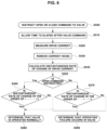
- FIG. 6 is a flowchart illustrating a process of determining an operating state of the integrated valve according to the present disclosure.
- whether an integrated valve is operated abnormally may be accurately and quickly determined, the operation abnormality of the integrated valve may be immediately responded, and thus problems caused by the operation abnormality of the integrated valve may be prevented.
- a height of water stored in the water trap is zero (0%)
- the integrated valve when the integrated valve is opened to purge only hydrogen stored in the water trap to an exhaust pipe of a fuel cell system, it is possible to prevent a hydrogen purge failure and an excessive hydrogen purge due to a malfunction of the integrated valve.
- FIG. 1 is a diagram illustrating a configuration of a fuel cell system according to an embodiment of the present disclosure.
- the fuel cell system may include a fuel cell stack 10 , a water trap 20 , an integrated valve 30 , a water level sensor 22 , a hydrogen pressure sensor 12 , and a controller 40 .
- the fuel cell system may include a configuration of a general fuel cell system in addition to the above configuration.
- the fuel cell system may include a hydrogen supply device for supplying hydrogen to the fuel cell stack 10 and an air supply device for supplying air to the fuel cell stack 10 .
- the fuel cell stack 10 is a power generation device which converts chemical energy of fuel into electrical energy by electrochemically reacting a fuel gas with an oxidant gas.
- the fuel cell stack 10 When hydrogen, which is a fuel gas, and oxygen in the air, which is an oxidant gas, chemically react with each other to generate electrical energy, the fuel cell stack 10 generates water due to the reaction of the hydrogen and the oxygen.
- the water generated in the fuel cell stack 10 falls due to gravity and is collected in the water trap 20 disposed below the fuel cell stack 10 .
- the water generated in the fuel cell stack 10 is discharged to the water trap 20 , some hydrogen in the fuel cell stack 10 is discharged to the water trap 20 together with the water.
- the water trap 20 stores the water and the hydrogen which are discharged from the fuel cell stack 10 and, when a height of the water stored in the water trap 20 exceeds a predetermined water level, the water trap 20 discharges the water to the outside of the fuel cell system and, when the discharge of the water is completed, the water trap 20 may begin to discharge the hydrogen.
- the water level sensor 22 is configured to detect the height of the water stored in the water trap 20
- the integrated valve 30 is configured to open or close a passage of the water trap 20 for discharging water and hydrogen.
- Hydrogen which is unreacted in the fuel cell stack 10 to be collected in the water trap 20 , is recycled to the fuel cell stack 10 and used. That is, the hydrogen recycled to the fuel cell stack 10 (i.e., the recycled hydrogen) is recovered to the fuel cell stack 10 via the water trap 20 .
- the hydrogen collected in the water trap 20 is not recycled to the fuel cell stack 10 and is discharged to the outside of the fuel cell system together with water.
- the discharge of the hydrogen collected in the water trap 20 to the outside of the fuel cell system is referred to as a “hydrogen purge.”
- the integrated valve 30 is configured to open or close a passage for discharging the water or the hydrogen stored in the water trap 20 to the exhaust pipe of the fuel cell system. That is, the integrated valve 30 is configured to open or close the passage of the water trap 20 connected to the exhaust pipe of the fuel cell system. In other words, the integrated valve 30 may be operated to open or close the passage through which the water and the hydrogen stored in the water trap 20 are discharged.
- the integrated valve 30 may be a solenoid valve which is operated when a drive current is applied.
- the integrated valve 30 may be a valve in which an inner passage of the integrated valve 30 is opened due to movement of a plunger to an open position when a drive current for an opening or closing operation is applied to a coil.
- the integrated valve 30 may include an inlet for introducing water and hydrogen and an outlet for discharging the water and the hydrogen, and the inner passage of the integrated valve 30 may be formed between the inlet and the outlet.
- the water and the hydrogen stored in the water trap 20 may be discharged to the exhaust pipe of the fuel cell system through the inner passage of the integrated valve 30 .
- the hydrogen pressure sensor 12 is installed on a hydrogen supply line 14 of the fuel cell stack 10 and configured to measure a pressure of hydrogen supplied to the fuel cell stack 10 .
- the controller 40 is configured to control an opening operation and a closing operation of the integrated valve 30 . Specifically, the controller 40 determines whether an operation of the integrated valve 30 is required and operates the integrated valve 30 in an open mode or a close mode, as necessary.
- the controller 40 determines a water level of the water trap 20 using a signal from the water level sensor 22 and detects a variation in water level of the water trap 20 .
- the controller 40 may determine whether a discharge of the water from the water trap 20 is completed through the signal from the water level sensor 22 . That is, whether the water is actually discharged from the water trap 20 is determined by the controller 40 based on the signal from the water level sensor 22 .
- the controller 40 opens the integrated valve 30 to purge the hydrogen to the exhaust pipe of the fuel cell system.
- the controller 40 may calculate an amount of the hydrogen purged (i.e., the hydrogen purge amount) to the exhaust pipe of the fuel cell system when the integrated valve 30 is opened on the basis of a time in which an open command of the integrated valve 30 is held from a time point at which the discharge of the water of the water trap 20 is completed.
- the controller 40 may estimate that the hydrogen having a high impurity ratio is discharged from the fuel cell stack 10 so that an inner hydrogen concentration of the fuel cell stack 10 is increased before the hydrogen purge of the water trap 20 is performed.
- the controller 40 may estimate the inner hydrogen concentration of the fuel cell stack 10 on the basis of an amount of hydrogen supplied to the fuel cell stack 10 from a hydrogen supply device (not shown) and an amount of the recycled hydrogen supplied to the fuel cell stack 10 from the water trap 20 .
- the controller 40 may estimate a hydrogen concentration of the fuel cell stack 10 based on the amount of the hydrogen supplied to the fuel cell stack 10 from the hydrogen supply device and a hydrogen purge amount discharged from the water trap 20 .
- the integrated valve 30 is opened to communicate with the atmosphere so that the controller 40 may perform a zero value correction on the hydrogen pressure sensor 12 installed in the hydrogen supply line 14 .
- the controller 40 may open the integrated valve 30 at regular periods to expose the hydrogen pressure sensor 12 to the atmosphere, thereby correcting a zero value of the hydrogen pressure sensor 12 .
- the zero value correction of the hydrogen pressure sensor 12 may be performed such that the integrated valve 30 is opened and thus the hydrogen pressure sensor 12 communicates with the atmosphere.
- the hydrogen pressure sensor 12 communicates with the atmosphere to detect an atmospheric pressure so the controller 40 learns a corrected value of the hydrogen pressure sensor 12 (i.e., the atmospheric pressure) when the hydrogen purge of the water trap 20 is completed.
- the controller 40 sets the pressure value (i.e., the atmospheric pressure) measured by the hydrogen pressure sensor 12 as a zero value of the hydrogen pressure sensor 12 .
- the controller 40 may determine whether opening and closing operations of the integrated valve 30 are performed normally based on information on the drive current for the opening operation of the integrated valve 30 .
- the integrated valve 30 When the drive current is supplied, the integrated valve 30 performs the opening operation, and when a supply of the drive current is interrupted, the integrated valve 30 performs the closing operation.
- the controller 40 may calculate an instantaneous rate of change (a slope) of the drive current over time to detect a variation in waveform of the drive current.
- the instantaneous rate of change of the drive current may be obtained by calculating a differential value of a function representing changes of the drive current over time.
- the controller 40 determines that the opening operation of the integrated valve 30 is operated normally and then completed.
- the controller 40 determines that the closing operation of the integrated valve 30 is operated normally and then completed.
- the controller 40 may determine whether the integrated valve 30 is operated normally based on the information on the instantaneous rate of change of the drive current.
- the controller 40 determines that the operation of the integrated valve 30 is not performed based on the information on the instantaneous rate of change of the drive current, that is, when the malfunction of the integrated valve 30 is diagnosed based on the information on the instantaneous rate of change of the drive current, in order to more accurately determine whether the integrated valve 30 fails, the controller 40 enters the integrated valve 30 into a forced driving mode.
- the controller 40 transmits an operation command according to a set open duty cycle and the number of times of opening operations to the integrated valve 30 .
- the open duty cycle may be an opening operation time of the integrated valve 30 .
- the integrated valve 30 forcibly repeats the opening and closing operations according to the number of times of the opening operations.
- the controller 40 in order to re-determine whether the integrated valve 30 fails, the controller 40 enters the integrated valve 30 into the forced driving mode in which the open duty cycle and the number of times of the opening operations of the integrated valve 30 are set.
- the integrated valve 30 When the integrated valve 30 is entered into the forced driving mode, the integrated valve 30 receives an operation command from the controller 40 according to a set open duty cycle and the number of times of the opening operations regardless of a real-time water level and a hydrogen amount in the water trap 20 .
- the open duty cycle of the integrated valve 30 may be set to 100%, and the number of times of the opening operations of the integrated valve 30 may be set to four.
- the open duty cycle of the integrated valve 30 may be a ratio to a predetermined reference operating time. For example, when the reference operating time of the integrated valve 30 is one second and the open duty cycle of the integrated valve 30 is 100%, the integrated valve 30 is opened for one second when operated once.
- the integrated valve 30 is periodically operated as many times as a set number of times of the opening operations.
- the open duty cycle of the integrated valve 30 may be increased and an opening operation interval thereof may be reduced when compared with a general driving mode.
- the general driving mode is an operating control mode of the integrated valve 30 for discharging water or hydrogen from the water trap 20 .
- the open duty cycle of the integrated valve 30 is controlled to less than 100%, and the integrated valve 30 is open-controlled when a discharge of the water or the hydrogen of the water trap 20 is necessary.
- the controller 40 determines operation abnormality of the integrated valve 30 based on the information on the instantaneous rate of change of the drive current, the controller 40 enters the integrated valve 30 into the forced driving mode and diagnoses the operation abnormality of the integrated valve 30 according to whether the integrated valve 30 entered into the forced driving mode is operated abnormally.
- the controller 40 determines the operation abnormality of the integrated valve 30 entered into the forced driving mode, the controller 40 confirms occurrence of a failure of the integrated valve 30 .
- the controller 40 when the controller 40 commands the opening operation of the integrated valve 30 and determines that the opening operation of the integrated valve 30 is not performed based on the information on the instantaneous rate of change of the drive current, the controller 40 immediately cancels an estimation of the inner hydrogen concentration of the fuel cell stack 10 not to perform the estimation.
- the controller 40 performs a hydrogen concentration estimation operation which is scheduled at an end time point of the opening operation of the integrated valve 30 .
- the controller 40 may include a hydrogen concentration estimation part for estimating the inner hydrogen concentration of the fuel cell stack 10 .
- the hydrogen concentration estimation part is not operated.
- the controller 40 when the controller 40 commands the opening operation of the integrated valve 30 and determines that the opening operation of the integrated valve 30 is not performed on the basis of the information on the instantaneous rate of change of the drive current, the controller 40 cancels learning of a corrected value of the hydrogen pressure sensor 12 , which is scheduled at an end time point of the opening operation of the integrated valve 30 , not to perform the learning.
- the controller 40 sets a signal value obtained from the hydrogen pressure sensor 12 as a zero value of the hydrogen pressure sensor 12 .
- the controller 40 may determine that the discharge of the hydrogen of the water trap 20 is performed normally.
- the controller 40 performs the learning of the corrected value of the hydrogen pressure sensor 12 and performs the estimation of the inner hydrogen concentration in the fuel cell stack 10 .
- the controller 40 When the water level of the water trap 20 is zero (0%) and the controller 40 diagnoses an operation abnormality of the integrated valve 30 , the controller 40 cancels the zero value correction of the hydrogen pressure sensor 12 so that it is possible to prevent a failure of the zero value correction of the hydrogen pressure sensor 12 and degradation of hydrogen fuel efficiency due to the failure.
- the controller 40 when the water level of the water trap 20 is zero (0%) and the controller 40 diagnoses an operation abnormality of the integrated valve 30 , the controller 40 cancels performing of a hydrogen concentration estimation of the fuel cell stack 10 to prevent a hydrogen concentration estimation error.
- the controller 40 determines that the integrated valve 30 is being operated in the open mode. However, even after a set time elapses, when the water level of the water trap 20 is not actually decreased, the controller 40 determines that a failure occurs due to clogging of a discharge passage of the integrated valve 30 .
- the controller 40 determines that the integrated valve 30 is operated in the open mode according to the command. However, when the water level of the water trap 20 is not reduced even though the water level of the water trap 20 is not zero, the controller 40 determines that the failure occurs due to the clogging of the discharge passage of the integrated valve 30 . When the discharge passage of the integrated valve 30 is clogged, even when the integrated valve 30 is operated to be opened, the discharge of the water of the water trap 20 is not performed.
- the controller 40 When the controller 40 commands a closing operation of the integrated valve 30 and determines that the closing operation of the integrated valve 30 is operated normally based on the information on the instantaneous rate of change of the drive current, the controller 40 calculates a hydrogen purge amount on the basis of a time in which an open command of the integrated valve 30 is held (i.e., an open command hold time) and estimates the inner hydrogen concentration of the fuel cell stack 10 using the hydrogen purge amount.
- the controller 40 calculates the hydrogen purge amount based on a time in which the open command of the integrated valve 30 is held from a time point at which the discharge of the water of the water trap 20 is completed.
- the controller 40 when the controller 40 commands the closing operation of the integrated valve 30 and determines that the closing operation of the integrated valve 30 is not performed based on the information on the instantaneous rate of change of the drive current, the controller 40 cancels the estimation of the inner hydrogen concentration of the fuel cell stack 10 and enters the integrated valve 30 into the forced driving mode.
- the controller 40 determines a failure of the integrated valve 30 .
- the controller 40 determines that the integrated valve 30 fails, the controller 40 measures a pressure of the hydrogen supplied to the fuel cell stack 10 through the hydrogen pressure sensor 12 and, subsequently, when it is determined that the pressure of the hydrogen supplied to the fuel cell stack 10 is decreased over time, the controller 40 interrupts the supply of the hydrogen to the fuel cell stack 10 .
- the controller 40 interrupts the supply of the hydrogen to the fuel cell stack 10 so that it is possible to prevent the hydrogen from excessively leaking into the atmosphere from the hydrogen supply line 14 and secure safety of vehicle occupants.
- the controller 40 When the controller 40 confirms the failure of the integrated valve 30 and determines that the pressure of the hydrogen supplied to the fuel cell stack 10 is not decreased, the controller 40 limits an output of the fuel cell stack 10 to operates the fuel cell stack 10 .
- the controller 40 determines that there is no leakage of the hydrogen into the air or that the leakage of the hydrogen into the air is insignificant.
- the controller 40 controls of the operation of the fuel cell stack 10 in a state of limiting the output of the fuel cell stack 10 . In this case, the output of the fuel cell stack 10 may be limited to less than or equal to a predetermined reference output.
- the controller 40 instructs an open command to the integrated valve 30 at S 100 and determines a water level of the water trap 20 based on a signal of the water level sensor 22 .
- the water level of the water trap 20 may be calculated in the range of 0% to 100% based on a height from a bottom surface of an inner side to a top surface of the inner side of the water trap 20 .
- the valve drive current is a drive current which is applied to a coil of the integrated valve 30 so as to operate the integrated valve 30 .
- a zero value correction of the hydrogen pressure sensor 12 and a hydrogen concentration estimation of the fuel cell stack 10 are performed at S 130 .
- an atmospheric pressure is corrected to a zero value.
- the inner hydrogen concentration estimation of the fuel cell stack 10 and the zero value correction of the hydrogen pressure sensor 12 are immediately canceled at S 140 , and the integrated valve 30 is entered into the forced driving mode at S 150 .
- Whether the integrated valve 30 which is entered into the forced driving mode, is operated to be opened or closed is determined based on the information on the instantaneous rate of change of the valve drive current at S 160 .
- the opening and closing operations of the integrated valve 30 are not performed normally, it is confirmed that a failure of the integrated valve 30 occurs at S 170 .
- the information on the instantaneous rate of change of the valve drive current is acquired, and it is determined whether the integrated valve 30 is operated to be opened based on the information on the instantaneous rate of change of the valve drive current at S 190 .
- an open command hold time a time in which an open command of the integrated valve 30 is held (i.e., an open command hold time) is measured, and the open command hold time is compared with a predetermined reference time at S 200 .
- the open command hold time elapses the reference time, the integrated valve 30 is actually operated to be opened, but the water level of the water trap 20 is not decreased so that it is confirmed that a failure of the integrated valve 30 occurs due to clogging of the discharge passage of the integrated valve 30 at S 210 .
- the inner hydrogen concentration estimation of the fuel cell stack 10 and the zero value correction of the hydrogen pressure sensor 12 are immediately canceled at S 140 , and the integrated valve 30 is entered into the forced driving mode at S 150 .
- Whether the integrated valve 30 entered into the forced driving mode is operated to be opened or closed is re-determined based on the information on the instantaneous rate of change of the valve drive current at S 160 .
- the opening and closing operations of the integrated valve 30 is not performed based on the information on the instantaneous rate of change of the valve drive current, the occurrence of the failure of the integrated valve 30 is confirmed at S 170 .
- the controller 40 instructs a close command to the integrated valve 30 at S 300 , the information on the instantaneous rate of change of the valve drive current is acquired, and it is determined whether the integrated valve 30 is operated to be closed based on the information on the instantaneous rate of change of the valve drive current at S 310 .
- an amount of the hydrogen discharged from the water trap 20 (i.e., a hydrogen purge amount) is calculated at S 320 and the inner hydrogen concentration of the fuel cell stack 10 is estimated at S 330 .
- the hydrogen purge amount may be calculated based on the time in which the open command of the integrated valve 30 is held.
- the open command is instructed to the integrated valve 30 (S 370 ).
- the opening or closing operation of the integrated valve 30 according to the forced driving mode is not performed, it is finally determined that the integrated valve 30 fails at S 380 .
- the pressure of the hydrogen supplied to the fuel cell stack 10 is measured at S 390 and it is determined whether the pressure of the hydrogen supplied to the fuel cell stack 10 is decreased at S 400 .
- the supply of the hydrogen to the fuel cell stack 10 is interrupted at S 410 .
- the valve drive current is periodically measured at S 520 and the instantaneous rate of change of the valve drive current is calculated at S 540 .
- the instantaneous rate of change of the valve drive current may be calculated in a manner of calculating a differential coefficient.
- noise of the valve drive current may be removed to filter current data at S 530 .
- the valve drive current is increased.
- the instantaneous rate of change of the valve drive current measured after the open command is instructed to the integrated valve 30 is changed from a positive (+) value to a negative ( ⁇ ) value and then changed from the negative ( ⁇ ) value to the positive (+) value again, it is determined that the integrated valve 30 is operated normally at S 580 .
- a condition in which the instantaneous rate of change of the valve drive current is changed from the positive (+) value to the negative ( ⁇ ) value and then changed from the negative ( ⁇ ) value to the positive (+) value again is not satisfied, it is determined that the failure due to the opening failure occurs in the integrated valve 30 at S 590 .
- the valve drive current is decreased.
- the instantaneous rate of change of the valve drive current measured after the integrated valve 30 receives the close command is changed from a negative value to a positive value and then changed from the positive value to the negative value again, it is determined that the integrated valve 30 is operated normally at S 580 .
- a condition in which the instantaneous rate of change of the valve drive current is changed from the negative value to the positive value and then changed from the positive value to the negative value again is not satisfied, it is determined that the failure due to the closing failure occurs in the integrated valve 30 at S 590 .
- the opening operation of the integrated valve 30 is completed so that the notch-shaped current waveform is generated as shown in Section a of FIG. 2 .
- the integrated valve 30 receives the close command, the closing operation of the integrated valve 30 is completed so that the lump-shaped current waveform is generated as shown in Section b of FIG. 2 .
- valve drive current When the valve drive current is applied to the integrated valve 30 , but the integrated valve 30 is not operated normally and a stuck failure occurs, a waveform of the valve drive current, such as the waveform in Section a or Section b of FIG. 2 , is not generated.
- whether the integrated valve 30 is operated normally is determined using a characteristic of the waveform of the valve drive current so that, in a situation in which the water level of the water trap 20 is 0%, whether the hydrogen purged is performed normally may be determined without additionally installing a separate pressure sensor in the water trap 20 .
- whether an integrated valve is operated normally can be determined using an operating characteristic of the integrated valve and, accordingly, whether an operation of the integrated valve is abnormal can be accurately determined without additionally installing a pressure sensor in a water trap, and it is possible to prevent a problem due to operation abnormality of the integrated valve by immediately responding to the operation abnormality of the integrated valve.
Landscapes
- Engineering & Computer Science (AREA)
- Manufacturing & Machinery (AREA)
- Sustainable Development (AREA)
- Sustainable Energy (AREA)
- Chemical & Material Sciences (AREA)
- Chemical Kinetics & Catalysis (AREA)
- Electrochemistry (AREA)
- General Chemical & Material Sciences (AREA)
- Life Sciences & Earth Sciences (AREA)
- Automation & Control Theory (AREA)
- Evolutionary Computation (AREA)
- Health & Medical Sciences (AREA)
- Artificial Intelligence (AREA)
- Computing Systems (AREA)
- Fuzzy Systems (AREA)
- Medical Informatics (AREA)
- Software Systems (AREA)
- Theoretical Computer Science (AREA)
- General Physics & Mathematics (AREA)
- Physics & Mathematics (AREA)
- Fuel Cell (AREA)
Abstract
Description
Claims (11)
Priority Applications (1)
| Application Number | Priority Date | Filing Date | Title |
|---|---|---|---|
| US18/756,673 US20240347748A1 (en) | 2020-10-26 | 2024-06-27 | Device for diagnosing valve failure of fuel cell system |
Applications Claiming Priority (2)
| Application Number | Priority Date | Filing Date | Title |
|---|---|---|---|
| KR10-2020-0138850 | 2020-10-26 | ||
| KR1020200138850A KR20220054924A (en) | 2020-10-26 | 2020-10-26 | Device for diagnosing valve failure of fuel cell system |
Related Child Applications (1)
| Application Number | Title | Priority Date | Filing Date |
|---|---|---|---|
| US18/756,673 Continuation US20240347748A1 (en) | 2020-10-26 | 2024-06-27 | Device for diagnosing valve failure of fuel cell system |
Publications (2)
| Publication Number | Publication Date |
|---|---|
| US20220131167A1 US20220131167A1 (en) | 2022-04-28 |
| US12051834B2 true US12051834B2 (en) | 2024-07-30 |
Family
ID=81257648
Family Applications (2)
| Application Number | Title | Priority Date | Filing Date |
|---|---|---|---|
| US17/412,707 Active 2042-10-07 US12051834B2 (en) | 2020-10-26 | 2021-08-26 | Device for diagnosing valve failure of fuel cell system |
| US18/756,673 Pending US20240347748A1 (en) | 2020-10-26 | 2024-06-27 | Device for diagnosing valve failure of fuel cell system |
Family Applications After (1)
| Application Number | Title | Priority Date | Filing Date |
|---|---|---|---|
| US18/756,673 Pending US20240347748A1 (en) | 2020-10-26 | 2024-06-27 | Device for diagnosing valve failure of fuel cell system |
Country Status (3)
| Country | Link |
|---|---|
| US (2) | US12051834B2 (en) |
| KR (1) | KR20220054924A (en) |
| CN (1) | CN114497648B (en) |
Families Citing this family (2)
| Publication number | Priority date | Publication date | Assignee | Title |
|---|---|---|---|---|
| CN115158104B (en) * | 2022-07-18 | 2023-07-11 | 中通客车股份有限公司 | Pressurizing control method and system for vehicle-mounted hydrogen system |
| DE102022124128A1 (en) * | 2022-09-20 | 2024-03-21 | Bayerische Motoren Werke Aktiengesellschaft | Computer-implemented method for detecting purge in a fuel cell |
Citations (2)
| Publication number | Priority date | Publication date | Assignee | Title |
|---|---|---|---|---|
| KR20170136738A (en) | 2016-06-02 | 2017-12-12 | 현대자동차주식회사 | Water trap for fuel cell system |
| US20200136158A1 (en) * | 2018-10-24 | 2020-04-30 | Hyundai Motor Company | Condensate water drain control system and control method for fuel cell |
Family Cites Families (3)
| Publication number | Priority date | Publication date | Assignee | Title |
|---|---|---|---|---|
| JP4609630B2 (en) * | 2004-04-21 | 2011-01-12 | トヨタ自動車株式会社 | Fuel cell valve abnormality determination control device |
| JP5066358B2 (en) * | 2006-12-21 | 2012-11-07 | 本田技研工業株式会社 | Fuel cell system and scavenging method thereof |
| KR102540876B1 (en) * | 2017-12-19 | 2023-06-07 | 현대자동차주식회사 | Apparatus for diagnosing fail in fuel cell |
-
2020
- 2020-10-26 KR KR1020200138850A patent/KR20220054924A/en active Pending
-
2021
- 2021-08-26 US US17/412,707 patent/US12051834B2/en active Active
- 2021-09-16 CN CN202111085699.2A patent/CN114497648B/en active Active
-
2024
- 2024-06-27 US US18/756,673 patent/US20240347748A1/en active Pending
Patent Citations (2)
| Publication number | Priority date | Publication date | Assignee | Title |
|---|---|---|---|---|
| KR20170136738A (en) | 2016-06-02 | 2017-12-12 | 현대자동차주식회사 | Water trap for fuel cell system |
| US20200136158A1 (en) * | 2018-10-24 | 2020-04-30 | Hyundai Motor Company | Condensate water drain control system and control method for fuel cell |
Also Published As
| Publication number | Publication date |
|---|---|
| US20220131167A1 (en) | 2022-04-28 |
| KR20220054924A (en) | 2022-05-03 |
| CN114497648A (en) | 2022-05-13 |
| CN114497648B (en) | 2026-02-10 |
| US20240347748A1 (en) | 2024-10-17 |
Similar Documents
| Publication | Publication Date | Title |
|---|---|---|
| US20240347748A1 (en) | Device for diagnosing valve failure of fuel cell system | |
| US10811709B2 (en) | Method of controlling purge of fuel cell system for vehicle | |
| KR102698999B1 (en) | Fuel cell hydrogen supply fault diagnosis system and diagnosis method | |
| US10598564B2 (en) | Apparatus and method for detecting leakage in hydrogen tank of hydrogen fuel cell vehicle | |
| US7882728B2 (en) | Dual anomaly judgment device for a fuel cell | |
| US9666887B2 (en) | Method for diagnosing current sensor of fuel cell system | |
| US7581431B2 (en) | Gas leak detection device and method for same | |
| CN101331638B (en) | Fuel cell system, mobile body equipped with fuel cell system, and abnormality judgment method for fuel cell system | |
| US8997771B2 (en) | Integrated pressure control actuator assembly of hydrogen supply system | |
| US20010016276A1 (en) | Fuel cell system and method | |
| CN100527512C (en) | Fuel battery system | |
| KR20090036594A (en) | Diagnosis method of fuel cell system and valve | |
| CN105552410A (en) | Fuel cell system, fuel cell vehicle, and method for evaluating operational failure of on-off valve | |
| US10971745B2 (en) | Cell reversal diagnostics for a fuel cell stack | |
| US20150226630A1 (en) | Airtightness evaluation device and airtightness evaluation method | |
| KR102706231B1 (en) | Condensate water drain control system and control method for fuel cell | |
| US11139493B2 (en) | Method and system for controlling hydrogen purging of fuel cell | |
| US6679111B2 (en) | Malfunction diagnostic apparatus for evaporated fuel purge system | |
| US11552316B2 (en) | Hydrogen supply control method and system of fuel cell system | |
| KR20120136824A (en) | Method for detecting leakage of oxygen and hydrogen in fuel cell system | |
| US12308493B2 (en) | Method of controlling fuel cell | |
| JP2003178789A (en) | Diagnostic device for fuel cell system | |
| JP5389485B2 (en) | Control method of fuel cell system | |
| CN117293360A (en) | Fuel cell system with hydrogen stacking pressure sensor clamping stagnation recognition function | |
| JP2020140918A (en) | Fuel cell system |
Legal Events
| Date | Code | Title | Description |
|---|---|---|---|
| AS | Assignment |
Owner name: KIA CORPORATION, KOREA, REPUBLIC OF Free format text: ASSIGNMENT OF ASSIGNORS INTEREST;ASSIGNORS:KIM, JONG GYUN;JEONG, SEONG CHEOL;REEL/FRAME:057300/0214 Effective date: 20210623 Owner name: HYUNDAI MOTOR COMPANY, KOREA, REPUBLIC OF Free format text: ASSIGNMENT OF ASSIGNORS INTEREST;ASSIGNORS:KIM, JONG GYUN;JEONG, SEONG CHEOL;REEL/FRAME:057300/0214 Effective date: 20210623 |
|
| FEPP | Fee payment procedure |
Free format text: ENTITY STATUS SET TO UNDISCOUNTED (ORIGINAL EVENT CODE: BIG.); ENTITY STATUS OF PATENT OWNER: LARGE ENTITY |
|
| STPP | Information on status: patent application and granting procedure in general |
Free format text: DOCKETED NEW CASE - READY FOR EXAMINATION |
|
| STPP | Information on status: patent application and granting procedure in general |
Free format text: NON FINAL ACTION MAILED |
|
| STPP | Information on status: patent application and granting procedure in general |
Free format text: RESPONSE TO NON-FINAL OFFICE ACTION ENTERED AND FORWARDED TO EXAMINER |
|
| STPP | Information on status: patent application and granting procedure in general |
Free format text: NOTICE OF ALLOWANCE MAILED -- APPLICATION RECEIVED IN OFFICE OF PUBLICATIONS |
|
| ZAAA | Notice of allowance and fees due |
Free format text: ORIGINAL CODE: NOA |
|
| ZAAB | Notice of allowance mailed |
Free format text: ORIGINAL CODE: MN/=. |
|
| STCF | Information on status: patent grant |
Free format text: PATENTED CASE |