US12051566B2 - Plasma processing apparatus - Google Patents
Plasma processing apparatus Download PDFInfo
- Publication number
- US12051566B2 US12051566B2 US17/648,436 US202217648436A US12051566B2 US 12051566 B2 US12051566 B2 US 12051566B2 US 202217648436 A US202217648436 A US 202217648436A US 12051566 B2 US12051566 B2 US 12051566B2
- Authority
- US
- United States
- Prior art keywords
- antenna
- plasma processing
- plasma
- ion trap
- gas
- Prior art date
- Legal status (The legal status is an assumption and is not a legal conclusion. Google has not performed a legal analysis and makes no representation as to the accuracy of the status listed.)
- Active, expires
Links
Images


Classifications
-
- C—CHEMISTRY; METALLURGY
- C23—COATING METALLIC MATERIAL; COATING MATERIAL WITH METALLIC MATERIAL; CHEMICAL SURFACE TREATMENT; DIFFUSION TREATMENT OF METALLIC MATERIAL; COATING BY VACUUM EVAPORATION, BY SPUTTERING, BY ION IMPLANTATION OR BY CHEMICAL VAPOUR DEPOSITION, IN GENERAL; INHIBITING CORROSION OF METALLIC MATERIAL OR INCRUSTATION IN GENERAL
- C23C—COATING METALLIC MATERIAL; COATING MATERIAL WITH METALLIC MATERIAL; SURFACE TREATMENT OF METALLIC MATERIAL BY DIFFUSION INTO THE SURFACE, BY CHEMICAL CONVERSION OR SUBSTITUTION; COATING BY VACUUM EVAPORATION, BY SPUTTERING, BY ION IMPLANTATION OR BY CHEMICAL VAPOUR DEPOSITION, IN GENERAL
- C23C16/00—Chemical coating by decomposition of gaseous compounds, without leaving reaction products of surface material in the coating, i.e. chemical vapour deposition [CVD] processes
- C23C16/22—Chemical coating by decomposition of gaseous compounds, without leaving reaction products of surface material in the coating, i.e. chemical vapour deposition [CVD] processes characterised by the deposition of inorganic material, other than metallic material
- C23C16/30—Deposition of compounds, mixtures or solid solutions, e.g. borides, carbides, nitrides
- C23C16/40—Oxides
- C23C16/401—Oxides containing silicon
-
- C—CHEMISTRY; METALLURGY
- C23—COATING METALLIC MATERIAL; COATING MATERIAL WITH METALLIC MATERIAL; CHEMICAL SURFACE TREATMENT; DIFFUSION TREATMENT OF METALLIC MATERIAL; COATING BY VACUUM EVAPORATION, BY SPUTTERING, BY ION IMPLANTATION OR BY CHEMICAL VAPOUR DEPOSITION, IN GENERAL; INHIBITING CORROSION OF METALLIC MATERIAL OR INCRUSTATION IN GENERAL
- C23C—COATING METALLIC MATERIAL; COATING MATERIAL WITH METALLIC MATERIAL; SURFACE TREATMENT OF METALLIC MATERIAL BY DIFFUSION INTO THE SURFACE, BY CHEMICAL CONVERSION OR SUBSTITUTION; COATING BY VACUUM EVAPORATION, BY SPUTTERING, BY ION IMPLANTATION OR BY CHEMICAL VAPOUR DEPOSITION, IN GENERAL
- C23C16/00—Chemical coating by decomposition of gaseous compounds, without leaving reaction products of surface material in the coating, i.e. chemical vapour deposition [CVD] processes
- C23C16/44—Chemical coating by decomposition of gaseous compounds, without leaving reaction products of surface material in the coating, i.e. chemical vapour deposition [CVD] processes characterised by the method of coating
- C23C16/458—Chemical coating by decomposition of gaseous compounds, without leaving reaction products of surface material in the coating, i.e. chemical vapour deposition [CVD] processes characterised by the method of coating characterised by the method used for supporting substrates in the reaction chamber
- C23C16/4581—Chemical coating by decomposition of gaseous compounds, without leaving reaction products of surface material in the coating, i.e. chemical vapour deposition [CVD] processes characterised by the method of coating characterised by the method used for supporting substrates in the reaction chamber characterised by material of construction or surface finish of the means for supporting the substrate
-
- C—CHEMISTRY; METALLURGY
- C23—COATING METALLIC MATERIAL; COATING MATERIAL WITH METALLIC MATERIAL; CHEMICAL SURFACE TREATMENT; DIFFUSION TREATMENT OF METALLIC MATERIAL; COATING BY VACUUM EVAPORATION, BY SPUTTERING, BY ION IMPLANTATION OR BY CHEMICAL VAPOUR DEPOSITION, IN GENERAL; INHIBITING CORROSION OF METALLIC MATERIAL OR INCRUSTATION IN GENERAL
- C23C—COATING METALLIC MATERIAL; COATING MATERIAL WITH METALLIC MATERIAL; SURFACE TREATMENT OF METALLIC MATERIAL BY DIFFUSION INTO THE SURFACE, BY CHEMICAL CONVERSION OR SUBSTITUTION; COATING BY VACUUM EVAPORATION, BY SPUTTERING, BY ION IMPLANTATION OR BY CHEMICAL VAPOUR DEPOSITION, IN GENERAL
- C23C16/00—Chemical coating by decomposition of gaseous compounds, without leaving reaction products of surface material in the coating, i.e. chemical vapour deposition [CVD] processes
- C23C16/44—Chemical coating by decomposition of gaseous compounds, without leaving reaction products of surface material in the coating, i.e. chemical vapour deposition [CVD] processes characterised by the method of coating
- C23C16/50—Chemical coating by decomposition of gaseous compounds, without leaving reaction products of surface material in the coating, i.e. chemical vapour deposition [CVD] processes characterised by the method of coating using electric discharges
-
- H—ELECTRICITY
- H01—ELECTRIC ELEMENTS
- H01J—ELECTRIC DISCHARGE TUBES OR DISCHARGE LAMPS
- H01J37/00—Discharge tubes with provision for introducing objects or material to be exposed to the discharge, e.g. for the purpose of examination or processing thereof
- H01J37/32—Gas-filled discharge tubes
- H01J37/32009—Arrangements for generation of plasma specially adapted for examination or treatment of objects, e.g. plasma sources
- H01J37/32082—Radio frequency generated discharge
-
- H—ELECTRICITY
- H01—ELECTRIC ELEMENTS
- H01J—ELECTRIC DISCHARGE TUBES OR DISCHARGE LAMPS
- H01J37/00—Discharge tubes with provision for introducing objects or material to be exposed to the discharge, e.g. for the purpose of examination or processing thereof
- H01J37/32—Gas-filled discharge tubes
- H01J37/32009—Arrangements for generation of plasma specially adapted for examination or treatment of objects, e.g. plasma sources
- H01J37/32422—Arrangement for selecting ions or species in the plasma
-
- H—ELECTRICITY
- H01—ELECTRIC ELEMENTS
- H01J—ELECTRIC DISCHARGE TUBES OR DISCHARGE LAMPS
- H01J37/00—Discharge tubes with provision for introducing objects or material to be exposed to the discharge, e.g. for the purpose of examination or processing thereof
- H01J37/32—Gas-filled discharge tubes
- H01J37/32431—Constructional details of the reactor
- H01J37/32715—Workpiece holder
-
- H—ELECTRICITY
- H01—ELECTRIC ELEMENTS
- H01L—SEMICONDUCTOR DEVICES NOT COVERED BY CLASS H10
- H01L21/00—Processes or apparatus adapted for the manufacture or treatment of semiconductor or solid state devices or of parts thereof
- H01L21/67—Apparatus specially adapted for handling semiconductor or electric solid state devices during manufacture or treatment thereof; Apparatus specially adapted for handling wafers during manufacture or treatment of semiconductor or electric solid state devices or components ; Apparatus not specifically provided for elsewhere
- H01L21/683—Apparatus specially adapted for handling semiconductor or electric solid state devices during manufacture or treatment thereof; Apparatus specially adapted for handling wafers during manufacture or treatment of semiconductor or electric solid state devices or components ; Apparatus not specifically provided for elsewhere for supporting or gripping
- H01L21/687—Apparatus specially adapted for handling semiconductor or electric solid state devices during manufacture or treatment thereof; Apparatus specially adapted for handling wafers during manufacture or treatment of semiconductor or electric solid state devices or components ; Apparatus not specifically provided for elsewhere for supporting or gripping using mechanical means, e.g. chucks, clamps or pinches
- H01L21/68714—Apparatus specially adapted for handling semiconductor or electric solid state devices during manufacture or treatment thereof; Apparatus specially adapted for handling wafers during manufacture or treatment of semiconductor or electric solid state devices or components ; Apparatus not specifically provided for elsewhere for supporting or gripping using mechanical means, e.g. chucks, clamps or pinches the wafers being placed on a susceptor, stage or support
- H01L21/68771—Apparatus specially adapted for handling semiconductor or electric solid state devices during manufacture or treatment thereof; Apparatus specially adapted for handling wafers during manufacture or treatment of semiconductor or electric solid state devices or components ; Apparatus not specifically provided for elsewhere for supporting or gripping using mechanical means, e.g. chucks, clamps or pinches the wafers being placed on a susceptor, stage or support characterised by supporting more than one semiconductor substrate
-
- H—ELECTRICITY
- H01—ELECTRIC ELEMENTS
- H01Q—ANTENNAS, i.e. RADIO AERIALS
- H01Q1/00—Details of, or arrangements associated with, antennas
- H01Q1/12—Supports; Mounting means
- H01Q1/22—Supports; Mounting means by structural association with other equipment or articles
-
- H10P72/7621—
-
- C—CHEMISTRY; METALLURGY
- C23—COATING METALLIC MATERIAL; COATING MATERIAL WITH METALLIC MATERIAL; CHEMICAL SURFACE TREATMENT; DIFFUSION TREATMENT OF METALLIC MATERIAL; COATING BY VACUUM EVAPORATION, BY SPUTTERING, BY ION IMPLANTATION OR BY CHEMICAL VAPOUR DEPOSITION, IN GENERAL; INHIBITING CORROSION OF METALLIC MATERIAL OR INCRUSTATION IN GENERAL
- C23C—COATING METALLIC MATERIAL; COATING MATERIAL WITH METALLIC MATERIAL; SURFACE TREATMENT OF METALLIC MATERIAL BY DIFFUSION INTO THE SURFACE, BY CHEMICAL CONVERSION OR SUBSTITUTION; COATING BY VACUUM EVAPORATION, BY SPUTTERING, BY ION IMPLANTATION OR BY CHEMICAL VAPOUR DEPOSITION, IN GENERAL
- C23C16/00—Chemical coating by decomposition of gaseous compounds, without leaving reaction products of surface material in the coating, i.e. chemical vapour deposition [CVD] processes
- C23C16/44—Chemical coating by decomposition of gaseous compounds, without leaving reaction products of surface material in the coating, i.e. chemical vapour deposition [CVD] processes characterised by the method of coating
- C23C16/458—Chemical coating by decomposition of gaseous compounds, without leaving reaction products of surface material in the coating, i.e. chemical vapour deposition [CVD] processes characterised by the method of coating characterised by the method used for supporting substrates in the reaction chamber
- C23C16/4582—Rigid and flat substrates, e.g. plates or discs
- C23C16/4583—Rigid and flat substrates, e.g. plates or discs the substrate being supported substantially horizontally
- C23C16/4584—Rigid and flat substrates, e.g. plates or discs the substrate being supported substantially horizontally the substrate being rotated
-
- H—ELECTRICITY
- H01—ELECTRIC ELEMENTS
- H01J—ELECTRIC DISCHARGE TUBES OR DISCHARGE LAMPS
- H01J2237/00—Discharge tubes exposing object to beam, e.g. for analysis treatment, etching, imaging
- H01J2237/20—Positioning, supporting, modifying or maintaining the physical state of objects being observed or treated
- H01J2237/202—Movement
- H01J2237/20214—Rotation
-
- H—ELECTRICITY
- H01—ELECTRIC ELEMENTS
- H01J—ELECTRIC DISCHARGE TUBES OR DISCHARGE LAMPS
- H01J2237/00—Discharge tubes exposing object to beam, e.g. for analysis treatment, etching, imaging
- H01J2237/32—Processing objects by plasma generation
- H01J2237/33—Processing objects by plasma generation characterised by the type of processing
- H01J2237/332—Coating
-
- H—ELECTRICITY
- H01—ELECTRIC ELEMENTS
- H01J—ELECTRIC DISCHARGE TUBES OR DISCHARGE LAMPS
- H01J37/00—Discharge tubes with provision for introducing objects or material to be exposed to the discharge, e.g. for the purpose of examination or processing thereof
- H01J37/32—Gas-filled discharge tubes
- H01J37/32009—Arrangements for generation of plasma specially adapted for examination or treatment of objects, e.g. plasma sources
- H01J37/32082—Radio frequency generated discharge
- H01J37/321—Radio frequency generated discharge the radio frequency energy being inductively coupled to the plasma
- H01J37/3211—Antennas, e.g. particular shapes of coils
-
- H—ELECTRICITY
- H01—ELECTRIC ELEMENTS
- H01J—ELECTRIC DISCHARGE TUBES OR DISCHARGE LAMPS
- H01J37/00—Discharge tubes with provision for introducing objects or material to be exposed to the discharge, e.g. for the purpose of examination or processing thereof
- H01J37/32—Gas-filled discharge tubes
- H01J37/32431—Constructional details of the reactor
- H01J37/3244—Gas supply means
-
- H—ELECTRICITY
- H01—ELECTRIC ELEMENTS
- H01L—SEMICONDUCTOR DEVICES NOT COVERED BY CLASS H10
- H01L21/00—Processes or apparatus adapted for the manufacture or treatment of semiconductor or solid state devices or of parts thereof
- H01L21/02—Manufacture or treatment of semiconductor devices or of parts thereof
- H01L21/02104—Forming layers
- H01L21/02107—Forming insulating materials on a substrate
- H01L21/02109—Forming insulating materials on a substrate characterised by the type of layer, e.g. type of material, porous/non-porous, pre-cursors, mixtures or laminates
- H01L21/02112—Forming insulating materials on a substrate characterised by the type of layer, e.g. type of material, porous/non-porous, pre-cursors, mixtures or laminates characterised by the material of the layer
- H01L21/02123—Forming insulating materials on a substrate characterised by the type of layer, e.g. type of material, porous/non-porous, pre-cursors, mixtures or laminates characterised by the material of the layer the material containing silicon
- H01L21/02164—Forming insulating materials on a substrate characterised by the type of layer, e.g. type of material, porous/non-porous, pre-cursors, mixtures or laminates characterised by the material of the layer the material containing silicon the material being a silicon oxide, e.g. SiO2
-
- H—ELECTRICITY
- H01—ELECTRIC ELEMENTS
- H01L—SEMICONDUCTOR DEVICES NOT COVERED BY CLASS H10
- H01L21/00—Processes or apparatus adapted for the manufacture or treatment of semiconductor or solid state devices or of parts thereof
- H01L21/02—Manufacture or treatment of semiconductor devices or of parts thereof
- H01L21/02104—Forming layers
- H01L21/02107—Forming insulating materials on a substrate
- H01L21/02225—Forming insulating materials on a substrate characterised by the process for the formation of the insulating layer
- H01L21/0226—Forming insulating materials on a substrate characterised by the process for the formation of the insulating layer formation by a deposition process
- H01L21/02263—Forming insulating materials on a substrate characterised by the process for the formation of the insulating layer formation by a deposition process deposition from the gas or vapour phase
- H01L21/02271—Forming insulating materials on a substrate characterised by the process for the formation of the insulating layer formation by a deposition process deposition from the gas or vapour phase deposition by decomposition or reaction of gaseous or vapour phase compounds, i.e. chemical vapour deposition
- H01L21/02274—Forming insulating materials on a substrate characterised by the process for the formation of the insulating layer formation by a deposition process deposition from the gas or vapour phase deposition by decomposition or reaction of gaseous or vapour phase compounds, i.e. chemical vapour deposition in the presence of a plasma [PECVD]
-
- H—ELECTRICITY
- H01—ELECTRIC ELEMENTS
- H01L—SEMICONDUCTOR DEVICES NOT COVERED BY CLASS H10
- H01L21/00—Processes or apparatus adapted for the manufacture or treatment of semiconductor or solid state devices or of parts thereof
- H01L21/67—Apparatus specially adapted for handling semiconductor or electric solid state devices during manufacture or treatment thereof; Apparatus specially adapted for handling wafers during manufacture or treatment of semiconductor or electric solid state devices or components ; Apparatus not specifically provided for elsewhere
- H01L21/683—Apparatus specially adapted for handling semiconductor or electric solid state devices during manufacture or treatment thereof; Apparatus specially adapted for handling wafers during manufacture or treatment of semiconductor or electric solid state devices or components ; Apparatus not specifically provided for elsewhere for supporting or gripping
- H01L21/687—Apparatus specially adapted for handling semiconductor or electric solid state devices during manufacture or treatment thereof; Apparatus specially adapted for handling wafers during manufacture or treatment of semiconductor or electric solid state devices or components ; Apparatus not specifically provided for elsewhere for supporting or gripping using mechanical means, e.g. chucks, clamps or pinches
- H01L21/68714—Apparatus specially adapted for handling semiconductor or electric solid state devices during manufacture or treatment thereof; Apparatus specially adapted for handling wafers during manufacture or treatment of semiconductor or electric solid state devices or components ; Apparatus not specifically provided for elsewhere for supporting or gripping using mechanical means, e.g. chucks, clamps or pinches the wafers being placed on a susceptor, stage or support
- H01L21/68764—Apparatus specially adapted for handling semiconductor or electric solid state devices during manufacture or treatment thereof; Apparatus specially adapted for handling wafers during manufacture or treatment of semiconductor or electric solid state devices or components ; Apparatus not specifically provided for elsewhere for supporting or gripping using mechanical means, e.g. chucks, clamps or pinches the wafers being placed on a susceptor, stage or support characterised by a movable susceptor, stage or support, others than those only rotating on their own vertical axis, e.g. susceptors on a rotating caroussel
-
- H10P14/6336—
-
- H10P14/69215—
-
- H10P72/7618—
Definitions
- the present disclosure relates to a plasma processing apparatus.
- Japanese Laid-Open Patent Application Publication No. 2018-41685 discloses a plasma processing apparatus including an antenna device that includes an antenna including a plurality of antenna members extending along a predetermined track-like shape and having longitudinal coupling positions opposite to each other in a shorter direction so as to form a predetermined track-like shape having a longitudinal direction and a shorter direction.
- the antenna includes a deformable and electrically conductive coupling member connecting the ends of the adjacent plurality of antenna members, and at least two vertical moving mechanisms individually coupled to at least two of the plurality of antenna members and capable of raising and lowering at least two of the plurality of antenna members so as to change the bending angle of the coupling member as a fulcrum.
- the present disclosure provides a plasma processing apparatus capable of regulating a supply of ions generated by plasma.
- a plasma processing apparatus including a process chamber.
- a turntable is disposed in the process chamber and is configured to receive a substrate along a circumferential direction thereof.
- a process gas supply nozzle is configured to supply a process gas to the turntable.
- a plasma antenna is disposed on the process chamber at a position covering at least a part of the process gas supply nozzle.
- An ion trap plate is disposed over the process gas supply nozzle at a position overlapping at least a part of the plasma antenna in the process chamber.
- FIG. 1 is a vertical schematic cross-sectional view illustrating a plasma processing apparatus according to an embodiment of the present disclosure
- FIG. 2 is a schematic plan view illustrating a configuration of a plasma processing apparatus according to an embodiment of the present disclosure
- FIG. 3 is a cross-sectional view along a concentric circle of a susceptor of a plasma processing apparatus according to an embodiment of the present disclosure
- FIG. 4 is an example of a longitudinal sectional view of a plasma generator of a plasma processing apparatus according to an embodiment of the present disclosure
- FIG. 5 is an exploded perspective view of an example of a plasma generator of a plasma processing apparatus according to an embodiment of the present disclosure
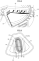
- FIG. 6 is a perspective view of an example of a housing disposed in a plasma generator of a plasma processing apparatus according to an embodiment of the present disclosure
- FIG. 7 is a vertical cross-sectional view of a plasma processing apparatus cut through a vacuum chamber along a rotational direction of a susceptor according to an embodiment of the present disclosure
- FIG. 8 is a perspective view illustrating an enlarged view of a gas nozzle for plasma processing disposed in a plasma processing region of a plasma processing apparatus according to an embodiment of the present disclosure
- FIG. 9 is a plan view of an example of a plasma generator of a plasma processing apparatus according to an embodiment of the present disclosure.
- FIG. 10 is a perspective view illustrating a part of a Faraday shield disposed in a plasma generator of a plasma processing apparatus according to an embodiment of the present disclosure
- FIG. 11 is a perspective view of a plasma processing apparatus according to embodiments of the present disclosure.
- FIG. 12 is a side view of a plasma processing apparatus according to an embodiment of the present disclosure.
- FIG. 13 is a side view of an antenna of a plasma processing apparatus according to an embodiment of the present disclosure.
- FIG. 14 is a diagram illustrating an example of a plasma processing apparatus including an ion trap plate according to an embodiment of the present disclosure
- FIG. 15 is a diagram illustrating an example of an ion trap plate
- FIG. 16 is a diagram illustrating an example of a movable ion trap plate.
- FIGS. 17 A and 17 B are diagrams illustrating an arrangement example of an ion trap plate in a vacuum chamber.
- FIG. 1 is a schematic vertical cross-sectional view illustrating an example of a plasma processing apparatus according to an embodiment of the present invention.
- FIG. 2 is a schematic plan view illustrating an example of the plasma processing apparatus according to the embodiment. In FIG. 2 , for convenience of explanation, a depiction of a top plate 11 is omitted.
- the plasma processing apparatus of the embodiment includes a vacuum chamber 1 having a substantially circular planar shape, and a susceptor 2 that is disposed in the vacuum chamber 1 such that the rotational center of the susceptor 2 coincides with the center of the vacuum chamber 1 .
- the susceptor 2 rotates wafers W placed thereon by rotating around its rotational center.
- the vacuum chamber 1 is a process chamber to accommodate wafers W therein and to perform a plasma process on a film or the like deposited on surfaces of the wafers W.
- the vacuum chamber 1 includes a top plate (ceiling) 11 that faces recesses 24 formed in a surface of the susceptor 2 , and a chamber body 12 .
- a ring-shaped seal member 13 is provided at the periphery of the upper surface of the chamber body 12 .
- the top plate 11 is configured to be attachable to and detachable from the chamber body 12 .
- the diameter (inside diameter) of the vacuum chamber 1 in plan view is, for example, about 1100 mm, but is not limited to this.
- a separation gas supply pipe 51 is connected to the center of the upper side of the vacuum chamber 1 (or the center of the top plate 11 ).
- the separation gas supply pipe 51 supplies a separation gas to a central area C in the vacuum chamber 1 to prevent different process gases from mixing with each other in the central area C.
- a central part of the susceptor 2 is fixed to an approximately-cylindrical core portion 21 .
- a rotational shaft 22 is connected to a lower surface of the core portion 21 and extends in the vertical direction.
- the susceptor 2 is configured to be rotatable by a drive unit 23 about the vertical axis of the rotational shaft 22 , in a clockwise fashion in the example of FIG. 2 .
- the diameter of the susceptor 2 is, for example, but is not limited to, about 1000 mm.
- the rotational shaft 22 and the drive unit 23 are housed in a case body 20 .
- An upper-side flange of the case body 20 is hermetically attached to the lower surface of a bottom part 14 of the vacuum chamber 1 .
- a purge gas supply pipe 72 is connected to the case body 20 .
- the purge gas supply pipe 72 supplies a purge gas (separation gas) such as argon gas to an area below the susceptor 2 .
- a part of the bottom part 14 of the vacuum chamber 1 surrounding the core portion 21 forms a ring-shaped protrusion 12 a that protrudes so as to approach the susceptor 2 from below.
- Circular recesses 24 (or substrate receiving areas), where the wafers W having a diameter of, for example, 300 mm are placed, are formed in the upper surface of the susceptor 2 .
- a plurality of (e.g., five) recesses 24 are provided along the rotational direction of the susceptor 2 .
- Each of the recesses 24 has an inner diameter that is slightly (e.g., from 1 mm to 4 mm) greater than the diameter of the wafer W.
- the depth of the recess 24 is substantially the same as or greater than the thickness of the wafer W.
- the height of the upper surface of the wafer W becomes substantially the same as or lower than the height of the upper surface of the susceptor 2 where the wafers W are not placed.
- the depth of the recess 24 is preferably less than or equal to about three times the thickness of the wafer W.
- Through holes are formed in the bottom of the recess 24 to allow a plurality of (e.g., three) lifting pins (which are described later) to pass through. The lifting pins raise and lower the wafer W.
- a first process area P 1 , a second process area P 2 and a third process area P 3 are provided apart from each other along the rotational direction of the susceptor 2 .
- the third process area P 3 is a plasma processing area, it may be also referred to as a plasma processing area P 3 hereinafter.
- a plurality of (e.g., seven) gas nozzles 31 , 32 , 33 , 34 , 35 , 41 , and 42 made of, for example, quartz are arranged at intervals in a circumferential direction of the vacuum chamber 1 .
- the gas nozzles 31 through 35 , 41 , and 42 extend radially, and are disposed to face areas that the recesses 24 of the susceptor 2 pass through.
- each of the gas nozzles 31 through 35 , 41 , and 42 extends horizontally from the outer wall of the vacuum chamber 1 toward the central area C so as to face the wafers W.
- the gas nozzle 35 extends from the outer wall of the vacuum chamber 1 toward the central area C, and then bends and extends linearly along the central area C in a counterclockwise fashion (opposite direction of the rotational direction of the susceptor 2 ). In the example of FIG.
- a gas supplied from the second process gas nozzle 32 is often similar to a gas supplied from the plasma processing gas nozzles 33 through 35 , but the second process gas nozzle 32 may not be necessarily provided when the plasma processing gas nozzles 33 through 35 sufficiently supply the gas.
- the plasma processing gas nozzles 33 to 35 may be substituted with a single plasma processing gas nozzle.
- a plasma processing gas nozzle extending from the outer peripheral wall of the vacuum chamber 1 toward the central region C may be disposed, similar to the second process gas nozzle 32 .
- the first process gas nozzle 31 forms a “first process gas supply part”.
- Each of the plasma processing gas nozzles 33 , 34 and 35 forms a “plasma processing gas supply part”.
- Each of the separation gas nozzles 41 and 42 forms a “separation gas supply part”.
- Each of the gas nozzles 31 through 35 , 41 , and 42 is connected to gas supply sources (not illustrated in the drawings) via a flow control valve.
- Gas discharge holes 36 for discharging a gas are formed in the lower side (which faces the susceptor 2 ) of each of the nozzles 31 through 35 , 41 , and 42 .
- the gas discharge holes 36 are formed, for example, at regular intervals along the radial direction of the susceptor 2 .
- the distance between the lower end of each of the nozzles 31 through 35 , 41 , and 42 and the upper surface of the susceptor 2 is, for example, from about 1 mm to about 5 mm.
- An area below the first process gas nozzle 31 is a first process area P 1 where a first process gas is adsorbed on the wafer W.
- An area below the second process gas nozzle 32 is a second process area P 2 where a second process gas that can produce a reaction product by reacting with the first process gas is supplied to the wafer W.
- An area below the plasma processing gas nozzles 33 through 35 is a third process area P 3 where a modification process is performed on a film on the wafer W.
- the separation gas nozzles 41 and 42 are provided to form separation areas D for separating the first process area P 1 from the second process area P 2 , and separating the third process area P 3 from the first process area P 1 , respectively.
- the separation area D is not provided between the second process area P 2 and the third process area P 3 .
- the second process gas supplied in the second process area P 2 and the mixed gas supplied in the third process area P 3 partially contain a common component therein in many cases, and therefore the second process area P 2 and the third process area P 3 do not have to be separated from each other by particularly using the separation gas.
- the first process gas nozzle 31 supplies a source gas that forms a principal component of a film to be deposited.
- the first process gas nozzle 31 supplies a silicon-containing gas such as an organic aminosilane gas.
- the second process gas nozzle 32 supplies an oxidation gas such as oxygen gas and ozone gas.
- the plasma processing gas nozzles 33 through 35 supply a mixed gas containing the same gas as the second process gas and a noble gas to perform a modification process on the deposited film.
- the plasma processing gas nozzles 33 through 35 supply a mixed gas of the oxidation gas such as oxygen gas and ozone gas same as the second process gas and a noble gas such as argon and helium. Because the plasma processing gas nozzles 33 to 35 are configured to supply gases to different regions on the susceptor 2 , the flow ratio of the noble gas may vary from region to region, and the modification process may be performed uniformly.
- FIG. 3 illustrates a cross section of a part of the substrate processing apparatus taken along a concentric circle of the susceptor 2 . More specifically, FIG. 3 illustrates a cross section of a part of the substrate processing apparatus from one of the separation areas D through the first process area P 1 to the other one of the separation areas D.
- Approximately fan-like convex portions 4 are provided on the lower surface of the top plate 11 of the vacuum chamber 1 at locations corresponding to the separation areas D.
- the convex portions 4 are attached to the back surface of the top plate 11 .
- flat and low ceiling surfaces 44 are formed by the lower surfaces of the convex portions 4
- ceiling surfaces 45 are formed by the lower surface of the top plate 11 .
- the ceiling surfaces 45 are located on both sides of the ceiling surfaces 44 in the circumferential direction, and are located higher than the ceiling surfaces 44 .
- each of the convex portions 4 forming the ceiling surface 44 has a fan-like planar shape whose apex is cut off to form an arc-shaped side. Also, a groove 43 extending in the radial direction is formed in each of the convex portions 4 at the center in the circumferential direction. Each of the separation gas nozzles 41 and 42 is placed in the groove 43 . A peripheral part of the convex portion 4 (a part along the outer edge of the vacuum chamber 1 ) is bent to form an L-shape to prevent the process gases from mixing with each other. The L-shaped part of the convex portion 4 faces the outer end surface of the susceptor 2 and is slightly apart from the chamber body 12 .
- a nozzle cover 230 is provided above the first process gas nozzle 31 .
- the nozzle cover 230 causes the first process gas to flow along the wafer W, and causes the separation gas to flow near the top plate 11 instead of near the wafer W.
- the nozzle cover 230 includes an approximately-box-shaped cover body 231 having an opening in the lower side to accommodate the first process gas nozzle 31 , and current plates 232 connected to the upstream and downstream edges of the opening of the cover body 231 in the rotational direction of the susceptor 2 .
- a side wall of the cover body 231 near the rotational center of the susceptor 2 extends toward the susceptor 2 to face a tip of the first process gas nozzle 31 .
- Another side wall of the cover body 231 near the outer edge of the susceptor 2 is partially cut off so as not to interfere with the first process gas nozzle 31 .
- a plasma generating device 80 is provided above the plasma processing gas nozzles 33 through 35 to convert a plasma processing gas discharged into the vacuum chamber 1 to plasma.
- FIG. 4 is a vertical cross-sectional view of an example of the plasma generating device 80 .
- FIG. 5 is an exploded perspective view of an example of the plasma generating device 80 .
- FIG. 6 is a perspective view of an example of a housing 90 of the plasma generating device 80 .
- the plasma generating device 80 is configured by winding an antenna 83 made of a metal wire or the like, for example, three times around a vertical axis in a coil form. In plan view, the plasma generating device 80 is disposed to surround a strip-shaped area extending in the radial direction of the susceptor 2 and to extend across the diameter of the wafer W on the susceptor 2 .
- the antenna 83 is connected through a matching box 84 to a high frequency power source 85 that has, for example, a frequency of 13.56 MHz and output power of 5000 W.
- the antenna 83 is hermetically separated from the inner area of the vacuum chamber 1 .
- a connection electrode 86 electrically connects the antenna 83 , the matching box 84 , and the high frequency power source 85 .
- the antenna 83 has a foldable configuration at the top and the bottom, and has a lifting mechanism enabling the antenna 83 to be folded automatically at the top and the bottom.
- FIG. 2 details thereof are omitted. The details are described later.
- an opening 11 a having an approximately fan-like shape in plan view is formed in the top plate 11 above the plasma processing gas nozzles 33 through 35 .
- the ion trap plate 140 is a shield plate for limiting the supply of generated plasma ions to the wafer W and for improving uniformity of plasma processing across a surface of the wafer W. Details of the ion trap plate 130 will be described later. First, components other than the ion trap plate 140 , which are necessary for the plasma processing apparatus, will be mainly described.
- a ring-shaped member 82 is hermetically attached to the periphery of the opening 11 a .
- the ring-shaped member 82 extends along the periphery of the opening 11 a .
- the housing 90 is hermetically attached to the inner circumferential surface of the ring-shaped member 82 . That is, the outer circumferential surface of the ring-shaped member 82 faces an inner surface 11 b of the opening 11 a of the top plate 11 , and the inner circumferential surface of the ring-shaped member 82 faces a flange part 90 a of the housing 90 .
- the housing 90 is placed via the ring-shaped member 82 in the opening 11 a to enable the antenna 83 to be placed at a position lower than the top plate 11 .
- the housing 90 may be made of a dielectric material such as quartz.
- the bottom surface of the housing 90 forms a ceiling surface 46 of the plasma processing area P 3 .
- an upper peripheral part surrounding the entire circumference of the housing 90 extends horizontally to form the flange part 90 a .
- a central part of the housing 90 in plan view is recessed toward the inner area of the vacuum chamber 1 .
- the housing 90 is arranged so as to extend across the diameter of the wafer W in the radial direction of the susceptor 2 when the wafer W is located under the housing 90 .
- a seal member 11 c such as an O-ring is provided between the ring-shaped member 82 and the top plate 11 .
- the internal atmosphere of the vacuum chamber 1 is hermetically sealed by the ring-shaped member 82 and the housing 90 .
- the ring-shaped member 82 and the housing 90 are placed in the opening 11 a , and the entire circumference of the housing 90 is pressed downward via a frame-shaped pressing member 91 that is placed on the upper surfaces of the ring-shaped member 82 and the housing 90 and extends along a contact region between the ring-shaped member 82 and the housing 90 .
- the pressing member 91 is fixed to the top plate 11 with, for example, bolts (not illustrated in the drawing).
- FIG. 5 a depiction of the ring-shaped member 82 is omitted for simplification.
- the housing 90 also includes a protrusion 92 that extends along the circumference of the housing 90 and protrudes vertically from the lower surface of the housing 90 toward the susceptor 2 .
- the protrusion 92 surrounds the second process area P 2 below the housing 90 .
- the plasma processing gas nozzles 33 through 35 are accommodated in an area surrounded by the inner circumferential surface of the protrusion 92 , the lower surface of the housing 90 , and the upper surface of the susceptor 2 .
- a part of the protrusion 92 near a base end (at the inner wall of the vacuum chamber 1 ) of each of the plasma processing gas nozzles 33 through 35 is cut off to form an arc-shaped cut-out that conforms to the outer shape of each of the plasma processing gas nozzles 33 through 35 .
- the protrusion 92 is formed along the circumference of the housing 90 .
- the protrusion 92 prevents the seal member 11 c from being directly exposed to plasma, i.e., isolates the seal member 11 c from the second process area P 2 . This causes plasma to pass through an area under the protrusion 92 even when plasma spreads from the second process area P 2 toward the seal member 11 c , thereby deactivating the plasma before reaching the seal member 11 c.
- the plasma processing gas nozzles 33 through 35 are provided in the third process area P 3 under the housing 90 , and are connected to an argon gas supply source 120 , a helium gas supply source 121 and an oxygen gas supply source 122 , respectively. Furthermore, corresponding flow controllers 130 , 131 and 132 are provided between the plasma processing gas nozzles 33 through 35 and the argon gas supply source 120 , the helium gas supply source 121 and the oxygen gas supply source 122 , respectively.
- Ar gas, He gas and O 2 gas are supplied from the argon gas supply source 120 , the helium gas supply source 121 and the oxygen gas supply source 122 to each of the plasma processing gas nozzles 33 through 35 at predetermined flow rates (mixing ratios, mix proportions) through each of the flow controllers 130 , 131 and 132 , and flow rates thereof are determined depending on supplied areas.
- the mixture of the above-described Ar gas, He gas, and O 2 gas is supplied to the single plasma processing gas nozzle.
- FIG. 7 is a vertical cross-sectional view of the vacuum chamber 1 taken along the rotational direction of the susceptor 2 .
- Ar gas is likely to intrude into an area under the housing 90 from a clearance between the susceptor 2 and the protrusion 92 by being brought by the rotation of the susceptor 2 .
- a gas is discharged to the clearance from the area under the housing 90 . More specifically, as illustrated in FIGS.
- the gas discharge holes 36 of the plasma processing gas nozzle 34 are arranged to face the clearance, that is, to face the upstream side in the rotational direction of the susceptor 2 and downward.
- a facing angle ⁇ of the gas discharge holes 36 of the plasma processing gas nozzle 33 relative to the vertical axis may be, for example, about 45 degrees as illustrated in FIG. 7 , or may be about 90 degrees so as to face the inner side wall of the protrusion 92 .
- the facing angle ⁇ of the gas discharge holes 36 may be set at an appropriate angle capable of properly preventing the intrusion of Ar gas in a range from 45 to 90 degrees depending on the intended use.
- FIG. 8 is an enlarged perspective view illustrating the plasma processing gas nozzles 33 through 35 provided in the plasma processing area P 3 .
- the plasma processing gas nozzle 33 is a nozzle capable of covering the whole of the recess 24 in which the wafer W is placed, and supplying a plasma processing gas to the entire surface of the wafer W.
- the plasma processing gas nozzle 34 is a nozzle provided slightly above the plasma processing gas nozzle 33 so as to approximately overlap the plasma processing gas nozzle 33 .
- the length of the plasma processing gas nozzle 34 is about half the length of the plasma processing gas nozzle 33 .
- the plasma processing gas nozzle 35 extends from the outer peripheral wall of the vacuum chamber 1 along the radius of the downstream side of the fan-like plasma process area P 3 in the rotational direction of the susceptor 2 , and has a shape bent linearly along the central area C after reaching the neighborhood of the central area C.
- the plasma processing gas nozzle 33 covering the whole area may be referred to as a base nozzle 33
- the plasma processing gas nozzle 34 covering only the outer area may be referred to as an outer nozzle 34
- the plasma processing gas nozzle 35 extending to the inside may be referred to as an axis-side nozzle 35 .
- the base nozzle 33 is a gas nozzle for supplying a plasma processing gas to the whole surface of the wafer W. As illustrated in FIG. 7 , the base gas nozzle 33 discharges the plasma processing gas toward the protrusion 92 forming the side surface separating the plasma process area P 3 from the other area.
- the outer nozzle 34 is a nozzle for supplying a plasma processing gas selectively to an outer area of the wafer W.
- the plasma processing gas supplied to the plasma process area P 3 is converted to plasma by passing through the highest part of the plasma process area P 3 , which is also close to the plasma generating device 80 . More specifically, because the plasma generating device 80 is provided above the plasma processing area P 3 , the plasma processing gas flowing along the ceiling surface 46 (see FIG. 7 ) of the plasma processing area P 3 is converted to plasma, which contributes to the plasma process. In other words, the neighborhood of the ceiling surface 46 of the plasma processing area P 3 forms a plasma generation area, and the plasma processing gas having passed the plasma generation area is properly converted to the plasma.
- the outer nozzle 34 performs a process for increasing a flow rate of a plasma processing gas supplied from the outer nozzle 34 and a flow speed of the plasma processing gas of the outer area when an amount of plasma process performed on a film deposited on the wafer W after the plasma process is obtained and the result of the amount of plasma process is insufficient in the outer area.
- the gas discharge holes 36 (not illustrated in the drawings) of the outer nozzle 34 are provided to face upward and the ceiling surface 46 of the plasma processing area P 3 , and are configured to lead the supplied plasma processing gas to the ceiling surface 46 of the plasma process area P 2 .
- the axis-side nozzle 35 is a nozzle for supplying a plasma processing gas selectively to an area near the axis of the susceptor 2 of the wafer W.
- the gas discharge holes 36 (not illustrated in the drawings) are formed only in a part of the tip of the axis-side nozzle 35 extending along the central area C, and are configured to supply the plasma processing gas to the area of the wafer W near the axis of the susceptor 2 .
- the gas discharge holes 36 also face upward and are provided at a location facing the ceiling surface 46 of the plasma processing area P 3 . This causes the plasma processing gas supplied from the axis-side nozzle 35 to immediately flow toward the plasma generation area and to be converted to plasma efficiently.
- the gas discharge holes 36 of the outer nozzle 34 are provided to face upward so as to face the ceiling surface 46 of the plasma processing area P 3 , and are configured to cause the plasma processing gas to flow toward the ceiling surface 46 of the plasma processing area P 3 .
- the axis-side nozzle 35 is a nozzle to mainly supply the plasma processing gas to the central area near the axial side of the susceptor 2 on the wafer W.
- the gas discharge holes 36 (not illustrated in the drawing) are formed only in a portion of the tip the axis-side nozzle 35 along the central area C, and are configured to supply the plasma processing gas to the area on the central side of the wafer W.
- the gas discharge holes 36 face upward and provided in a position opposite to the ceiling surface 456 of the plasma processing area P 3 .
- the plasma processing gas supplied from the axis-side nozzle 35 immediately goes toward the plasma generation area and is efficiently converted to plasma.
- the flow ratio (mixing ratio, or mix proportion) of the noble gas and the reaction gas contained in the mixed gas can be adjusted for each area, thereby adjusting the quantity of processing across the surface of the film on the wafer W.
- the adjustment of the quantity of processing across the surface of the wafer W is generally performed to improve the uniformity of the plasma process across the surface of the wafer W, but when making a difference of the amount of plasma process for each area is desired, a flow ratio of helium gas contained in the plasma processing gas supplied from the nozzles 33 through 35 to the area desired to increase the quantity of processing just has to be increased, and the mixing ratio (mix proportion) of helium gas just has to be increased. Accordingly, in addition to the improvement of the process uniformity across the surface of the wafer W, a variety of adjustments of the quantity of processing is possible.
- the adjustment of the amount of plasma process across the surface can be performed readily and accurately.
- FIG. 8 although an example of including three of the plasma processing gas nozzles 33 through 35 is illustrated, the adjustment of the quantity of processing across the surface may be performed more finely and accurately by installing more plasma processing gas nozzles. The number, a shape, an installation location and the like of the plasma processing gas nozzles 33 through 35 can be changed depending on the intended use.
- a Faraday shield 95 of the plasma generating device 80 As illustrated in FIGS. 4 and 5 , a Faraday shield 95 is provided on the upper side of the housing 90 .
- the Faraday shield 95 is grounded, and is composed of a conductive plate-like part such as a metal plate (e.g., copper plate) that is shaped to roughly conform to the internal shape of the housing 90 .
- the Faraday shield 95 includes a horizontal surface 95 a that extends horizontally along the bottom surface of the housing 90 , and a vertical surface 95 b that extends upward from the outer edge of the horizontal surface 95 a and surrounds the horizontal surface 95 a .
- the Faraday shield 95 may be configured to be, for example, a substantially hexagonal shape in a plan view.
- FIG. 9 is a plan view of an example of the plasma generating device 80 .
- FIG. 10 is a perspective view of a part of the Faraday shield 95 provided in the plasma generating device 80 .
- the right and left upper ends of the Faraday shield 95 extend horizontally rightward and leftward, respectively, to form supports 96 .
- a frame 99 is provided between the Faraday shield 95 and the housing 90 to support the supports 96 from below.
- the frame 99 is supported by a part of the housing 90 near the central area C and a part of the flange part 90 a near the outer edge of the susceptor 2 .
- a plurality of slits 97 is formed in the horizontal surface 95 a .
- the slits 97 prevent an electric-field component of an electric field and a magnetic field (electromagnetic field) generated by the antenna 83 from reaching the wafer W below the Faraday shield 95 , and allow a magnetic field component of the electromagnetic field to reach the wafer W.
- the slits 97 extend in directions that are orthogonal to the direction in which the antenna 83 is wound, and are arranged to form a circle below the antenna 83 .
- the width of each slit 97 is set at a value that is about 1/10000 or less of the wavelength of a high frequency supplied to the antenna 83 .
- Circular electrically-conducting paths 97 a made of, for example, a grounded conductor are provided at the ends in the length direction of the slits 97 to close the open ends of the slits 97 .
- An opening 98 is formed in an area of the Faraday shield 95 where the slits 97 are not formed, i.e., an area surrounded by the antenna 83 .
- the opening 98 is used to check whether plasma is emitting light.
- the slits 97 are omitted for simplification, but an area where the slits 97 are formed is indicated by a dashed-dotted line.
- an insulating plate 94 is stacked on the horizontal surface 95 a of the Faraday shield 95 .
- the insulating plate 94 is made of, for example, quartz having a thickness of about 2 mm, and is used for insulation between the Faraday shield 95 and the plasma generating device 80 disposed over the Faraday shield 95 .
- the plasma generating device 80 is arranged to cover the inside of the vacuum chamber 1 (i.e., the wafer W on the susceptor 2 ) through the housing 90 , the Faraday shield 95 , and the insulating plate 94 .
- FIG. 11 is a perspective view of an antenna device 81 and a plasma generating device 80 .
- FIG. 12 is a side view of an antenna device 81 and a plasma generating device 80 .
- the antenna device 81 includes an antenna 83 , a connection electrode 86 , a lifting mechanism 87 , a linear encoder 88 , and a fulcrum jig 89 .
- the plasma generating device 80 further includes the antenna device 81 , a matching box 84 , and a radio frequency power source 85 .
- the antenna 83 includes an antenna member 830 , a coupling member 831 and a spacer 832 .
- the antenna 83 is generally configured in a coil shape, or a track-like shape, and is planar in an elongate annular shape having a longitudinal direction and a shorter direction (or a width direction).
- the planar shape may be an ellipse having an angle or a shape close to a rectangular frame having an angle.
- Such a track-like shape of antenna 83 is formed by coupling the antenna members 830 .
- the antenna member 830 is part of the antenna 83 and is formed by connecting ends of a plurality of small antenna members 830 extending along the track-like shape.
- the antenna member 830 includes a straight portion 8301 having a straight shape and curved portion 8302 having a curved shape for bending and connecting the straight portions 8301 .
- the antenna members 830 are connected to antenna members 830 a and 830 b at both ends and the antenna members 830 c and 830 d at central portions to form a track-like shape as a whole.
- the antenna 83 has, as an overall shape, the antenna members 830 a and 830 b at both ends having a shape close to an arc, and the antenna members 830 c and 830 d at the central portions having a linear shape.
- the antenna members 830 a and 830 b at the ends of the antenna members 830 c and 830 d in the shape close to the arc are connected to each other with the antenna members 830 c and 830 d in the central linear shape, and the central antenna members 830 c and 830 d are substantially parallel to each other.
- the antenna 83 is generally shaped such that the antenna members 830 c and 830 d have a long side and the antenna members 830 a and 830 b have a short side.
- the antenna members 830 a and 830 b are formed in a shape that approximates an arc shape where three straight portions 8301 are connected via two curved portions 8302 .
- the antenna member 830 c is composed of one long straight portion 8301 .
- the antenna member 830 d is formed by forming two long straight portions 8301 and one short straight portion between them with steps at the top and the bottom, so that two small curved portions 8302 are formed by being coupled to each other.
- the antenna member 830 forms a multi-stage track-like shape as a whole, and in FIGS. 11 and 12 , an antenna member 830 is illustrated forming a three-stage track-like shape.
- the coupling member 831 is a member for connecting adjacent antenna members 830 to each other and is made with a material that is conductive and can be deformed.
- the coupling member 831 may be made with, for example, a flexible substrate or the like, and may be made with a copper material.
- the copper material is a highly conductive and a soft material, and is suitable for coupling the antenna members 830 to each other.
- the coupling members 831 are made with a flexible material, it is possible to bend the antenna members 830 with the coupling members 831 as a fulcrum. This allows the antenna members 830 to be maintained in a bent state at the point of the coupling members 831 , while allowing the configuration of the antenna 83 to be varied.
- the distance between the antenna 83 and the wafer W is likely to affect the intensity of the plasma process. When the antenna 83 is brought close to the wafer W, the intensity of the plasma process is likely to increase, and when the antenna 83 is removed from the wafer W, the intensity of the plasma process is likely to decrease.
- the wafer W When the wafer W is loaded on the recess 24 of the susceptor 2 and the susceptor 2 is rotated to perform the plasma process, the wafer W is positioned along the circumferential direction of the susceptor 2 , and the moving speed of the center side of the susceptor 2 is low and the moving speed of the outer side is high.
- the intensity (or processing amount) of the plasma process at the center of the wafer W which is irradiated with plasma for a long time, is likely to be higher than the intensity of the plasma process at the outer periphery.
- the central plasma processing intensity is reduced; the peripheral plasma processing intensity is increased, and the overall plasma processing amount is uniform in the radial direction of the susceptor 2 .
- each other four coupling members 831 are provided for connecting four antenna members 830 a to 830 d to each other.
- the number of antenna members 830 and connecting members 831 may be increased or decreased depending on the application.
- the antenna members 830 a and 830 b at both ends may be present, which may be configured in a long U-shaped shape extending not only at both ends but also to the central portion, and the two antenna members 830 a and the antenna members 830 b are connected by the two coupling members 831 .
- four antenna members 830 may be disposed at the center to increase the bendable portion.
- facing coupling members 831 are preferably disposed at the same position in the longitudinal direction, that is, equal in length in the longitudinal direction of the facing antenna members 830 .
- the antenna 83 is preferably configured to change its height in the longitudinal direction, while using the bending points facing each other in the shorter direction and coinciding with each other in the longitudinal direction.
- the coupling members 831 coupling the antenna member 830 a to the antenna member 830 c and the coupling members 831 coupling the antenna member 830 a to the antenna member 830 d are configured to face each other in the shorter direction and be in the same position in the longitudinal direction.
- the coupling member 831 which couples the antenna member 830 b to the antenna member 830 c
- the coupling member 831 which couples the antenna member 830 b to the antenna member 830 d
- the coupling member 831 which couples the antenna member 830 b to the antenna member 830 d
- a spacer 832 is a member for separating multi-stage antenna members 830 disposed at an upper stage and a lower stage from each other so that even if antenna 83 is deformed, the antenna members 830 do not contact the upper and lower stages and do not cause a short circuit.
- the lifting mechanism 87 is a vertical motion mechanism for moving the antenna member 830 up and down.
- the lifting mechanism 87 includes an antenna retainer 870 , a drive unit 871 , and a frame 872 .
- the antenna retainer 870 is the retaining portion of the antenna 83 and the drive unit 871 is a driving part for moving the antenna 83 up and down through the antenna retainer 870 .
- the antenna retainer 870 may have various configurations if it can hold the antenna member 830 of the antenna 83 , but may be constructed to hold the antenna member 830 around the perimeter of the antenna member 830 , for example, as illustrated in FIG. 12 .
- the drive unit 871 may also use various drivers if the antenna members 830 can be moved up and down, for example, an air cylinder for air drive may be used.
- an air cylinder for air drive may be used.
- FIG. 12 an example is illustrated in which an air cylinder is applied to the drive unit 871 of the lifting mechanism 87 .
- a motor or the like may be used for the lofting mechanism 87 .
- a frame 872 is a support for holding the drive unit 871 , and holds the drive unit 871 at an appropriate position.
- the antenna retainer 870 is retained by the drive unit 871 .
- the lifting mechanism 87 is disposed for at least two or more of the antenna members 830 a to 830 d individually.
- deformation of the antenna 83 is performed automatically using the lifting mechanism 87 , rather than being adjusted by the operator.
- each of the antenna members 830 a to 830 d individually includes the lifting mechanism 87 , each of which operates independently.
- the lifting mechanism 87 is preferably disposed for each of the antenna members 830 a to 830 d , and the lifting mechanism 87 is disposed for at least two of the antenna members 830 a to 830 d even when the lifting mechanism 87 is not disposed for each of the antenna members 830 a to 830 d.
- FIGS. 11 and 12 only a single lifting mechanism 87 is shown, but actually, the lifting mechanism 87 is disposed for each of the antenna members 830 a to 830 d to be bent.
- the lifting mechanism 87 is disposed for each of the antenna members 830 a to 830 d to be bent.
- the antenna members 830 a , 830 c and 830 d can be deformed in any shape.
- the lifting mechanism 87 corresponding to the antenna member 830 a may be pulled up, and the lifting mechanisms 87 corresponding to the antenna members 830 c and 830 d may be fixed or lowered, and the antenna members 83 may be deformed by cooperating with a plurality of lifting mechanisms 87 . While it is not necessary to do so when the coupling member 831 is sufficiently soft to allow the antenna 83 to bend only by the corresponding lifting mechanism 87 . However, while the coupling member 831 may be deformable, when it is necessary to apply some force to the deformation, the plurality of lifting mechanism 87 may cooperate to perform the bending action of the antenna 83 .
- the bending of the antenna 83 is performed by changing the angle formed between the antenna members 830 a to 830 d on both sides of the coupling member 831 , while serving the coupling member 831 as the fulcrum.
- a linear encoder 88 is a device that detects the position of the linear axis and outputs position information. This allows accurate measurement of the distance of the antenna member 830 a from the top face of the Faraday shield 95 .
- the linear encoder 88 may be disposed at any position where precise position information is desired, and a plurality of the linear encoders may be disposed.
- the linear encoder 88 may be any type including an optical, a magnetic, or an electromagnetic inductive type, as long as the position and height of the antenna 83 can be measured. Additionally, as long as the position and height of the antenna 83 can be measured, a height measuring unit other than the linear encoder 88 may be used.
- the fulcrum jig 89 is a member for pivotally securing the lowermost antenna member 830 . This facilitates tilting the antenna 83 .
- the fulcrum jig 89 is provided to support the antenna member 830 b of the lowermost stage at the end of the outer peripheral side. This is because, as noted above, the antenna 83 is often deformed to increase the center side.
- it is not mandatory to provide the fulcrum jig 89 but rather it is preferable to provide the lifting mechanism 87 that moves the antenna member 830 b up and down.
- the connection electrode 86 includes an antenna connecting part 860 and an adjustment busbar 861 .
- the connection electrode 86 is a connection wire that serves as a framing to supply the antenna 83 with high frequency power output from the radio frequency power source 85 .
- the antenna connecting part 860 is an interconnection directly connected to the antenna 83
- the adjustment busbar 861 is a part of the antenna connecting part 860 having a resilient structure to absorb the deformation when the antenna connecting part 860 is moved up and down by the vertical movement of the antenna 83 . Because the antenna connecting part 860 is an electrode, the antenna connecting part 860 is made with an electrically conductive material such as metal.
- antenna device 81 and plasma generation apparatus 80 may be used that can automatically transform the shape of the antenna 83 into any shape.
- FIG. 13 is a side view of an antenna 83 according to an embodiment of the present disclosure. As illustrated in FIG. 13 , the bending angle of the antenna member 830 may be varied with the coupling member 831 as well as the height of the antenna member 830 depending on the location.
- the height of the antenna member 830 a is too high, the distance between the bottom surface of the housing 90 and the antenna member 830 a is increased, and the plasma power is unlikely to reach the vacuum chamber 1 . As a result, a phenomenon occurs where plasma is unlikely to ignite and unlikely to activate. Specifically, for example, if the height of the antenna member 830 a is 20 mm or higher, such a phenomenon is likely to occur.
- the height of the antenna member 830 a is lowered as low as possible, and an ion trap plate 140 is provided in the vacuum chamber 1 to compensate for the lack of adjustment amount (see FIG. 4 ).
- FIG. 14 is a diagram illustrating an example of a plasma processing apparatus including an ion trap plate according to an embodiment.
- FIG. 14 illustrates an enlarged plasma processing area P 3 .
- FIG. 14 shows a plasma processing area P 3 transparently, but because the housing 90 is actually transparent, it is equivalent to a top view.
- a plasma trap plate 140 is disposed in the vacuum chamber 1 .
- the ion trap plate 140 is configured to overlap a portion of the outer edge of the bottom surface of the housing 90 .
- a portion of a covering area 83 c between a point 83 a and a point 83 b of the antenna 83 is covered with the ion trap plate 140 .
- the covering area 83 c includes a broad area at the center of the susceptor 2 of the antenna 83 , but does not include the most outer area. That is, much of the central area of the antenna 83 is covered with the ion trap plate 140 , but the peripheral area of the antenna 83 is covered less or not at all.
- the ion trap plate 140 may be referred to as an ion block plate or an ion shield plate. Therefore, even if the set height of the antenna 83 (the antenna member 830 a ) is lowered, the oxidizing power of the central axis side region of the susceptor 2 is reduced, and the plasma oxidizing power in the radial direction can be made uniform.
- the ion trap plate 140 may not necessarily trap ions, but may block ions, and it may be possible to partially restrict the supply of oxidizing gas ions to the wafer W in an area on the central axis side of the antenna 83 .
- the height of the antenna member 830 a it is possible to set the height of the antenna member 830 a to 15 mm, 10 mm, 0 mm, and 15 mm or less and to prevent the plasma from being extinguished and from failing to ignite.
- the shape of the ion trap plate 140 and the area overlapping the antenna 83 can be set in various ways depending on the use application.
- the planar shape of the ion trap plate 140 is configured to diagonally traverse the antenna 83 , but various modifications are possible depending on the use application.
- FIG. 15 is a diagram illustrating an example of an ion trap plate 140 .
- the ion trap plate 140 has a circumferentially extending side 141 on the central axis side of the susceptor 2 and a radially extending side 145 .
- the ion trap plate 140 in order to connect the end of the central axis side 141 to the outer peripheral end of radially extending side 145 , also has a radially obliquely extending side 142 , a circumferentially extending side 143 , and a curve 144 formed by rounding the sides 142 and 143 and curvaceously connecting the side 142 to the side 143 so as to form a curved angle.
- the ion trap plate 140 is literally formed as a plate. This is because the space in the vacuum chamber 1 is limited and because the thin plate shape is sufficient to perform a function of blocking or trapping ions.
- a material for the ion trap plate 140 suitable to the application may be used as long as the ion trap plate can block or trap ions, and quartz may be used, for example. Quartz can be suitably utilized because the housing 90 is also quartz, and quartz can withstand high temperatures, and is unlikely to cause contamination.
- FIG. 16 illustrates an example of a movable ion trap plate 146 .
- a pivot shaft 150 may be disposed, and an area covering the antenna 83 may be changed by rotating the movable ion trap plate 146 about the pivot shaft 150 .
- the entire configuration is formed small and formed into a movable shape within the plasma processing area P 3 .
- the tip is narrowed and the overall width is smaller than the ion trap plate 140 .
- the movable configuration allows adjustment of the amounts of trapped ions and blocked ions depending on the process, and fine adjustment of the oxidizing power.
- a mobile ion trap plate 146 may be adopted.
- FIGS. 17 A and 17 B are diagrams illustrating an example of an arrangement of an ion trap plate in a vacuum chamber 1 .
- FIG. 17 A illustrates an example of an ion trap plate 147 disposed in a left area of the housing 90 .
- the ion trap plate 147 can be positioned both on the right side and the left side as long as the ion trap plate 47 efficiently covers the area on the central axis side of the antenna 83 .
- FIG. 17 B is a partial cross-sectional view illustrating an example of a vertical structure of a plasma processing apparatus including an ion trap plate 147 .
- the ion trap plate 147 is disposed on the plasma processing gas nozzles 33 to 35 .
- the ion trap plate 147 may have a plurality of stops 148 and be fixed to the plasma processing gas nozzles 33 to 35 .
- FIG. 17 B illustrates an example of the ion trap plate 147 being disposed on the plasma processing gas nozzles 33 to 35 , but the ion trap plate 147 may be supported by a separate support and disposed above the plasma processing gas nozzles 33 to 35 .
- the ion trap plates 140 and 146 may be disposed in the vacuum chamber 1 in the same manner as the ion trap plate 147 .
- ions can be trapped and the oxidizing power can be adjusted without hindering the flow of the plasma processing gas.
- the supply of ions generated by a plasma antenna can be adjusted.
Landscapes
- Chemical & Material Sciences (AREA)
- Engineering & Computer Science (AREA)
- Physics & Mathematics (AREA)
- Plasma & Fusion (AREA)
- Analytical Chemistry (AREA)
- Chemical Kinetics & Catalysis (AREA)
- Mechanical Engineering (AREA)
- Metallurgy (AREA)
- Organic Chemistry (AREA)
- General Chemical & Material Sciences (AREA)
- Materials Engineering (AREA)
- Inorganic Chemistry (AREA)
- Plasma Technology (AREA)
- Chemical Vapour Deposition (AREA)
- Condensed Matter Physics & Semiconductors (AREA)
- Computer Hardware Design (AREA)
- Microelectronics & Electronic Packaging (AREA)
- Power Engineering (AREA)
- Manufacturing & Machinery (AREA)
- General Physics & Mathematics (AREA)
- Physical Or Chemical Processes And Apparatus (AREA)
Abstract
Description
Claims (10)
Applications Claiming Priority (2)
| Application Number | Priority Date | Filing Date | Title |
|---|---|---|---|
| JP2021008287A JP7500450B2 (en) | 2021-01-21 | 2021-01-21 | Plasma Processing Equipment |
| JP2021-008287 | 2021-01-21 |
Publications (2)
| Publication Number | Publication Date |
|---|---|
| US20220230852A1 US20220230852A1 (en) | 2022-07-21 |
| US12051566B2 true US12051566B2 (en) | 2024-07-30 |
Family
ID=82405314
Family Applications (1)
| Application Number | Title | Priority Date | Filing Date |
|---|---|---|---|
| US17/648,436 Active 2043-01-30 US12051566B2 (en) | 2021-01-21 | 2022-01-20 | Plasma processing apparatus |
Country Status (4)
| Country | Link |
|---|---|
| US (1) | US12051566B2 (en) |
| JP (1) | JP7500450B2 (en) |
| KR (1) | KR102892586B1 (en) |
| CN (1) | CN114807908A (en) |
Families Citing this family (3)
| Publication number | Priority date | Publication date | Assignee | Title |
|---|---|---|---|---|
| JP7500450B2 (en) * | 2021-01-21 | 2024-06-17 | 東京エレクトロン株式会社 | Plasma Processing Equipment |
| KR102823594B1 (en) * | 2022-01-28 | 2025-06-23 | 주식회사 유진테크 | Apparatus and method for processing substrate |
| JP2025005048A (en) | 2023-06-27 | 2025-01-16 | 東京エレクトロン株式会社 | Substrate processing method |
Citations (35)
| Publication number | Priority date | Publication date | Assignee | Title |
|---|---|---|---|---|
| JP2006019414A (en) * | 2004-06-30 | 2006-01-19 | Canon Inc | Plasma processing equipment |
| US20080101978A1 (en) * | 2006-10-30 | 2008-05-01 | Elmira Ryabova | Method and apparatus for photomask etching |
| US20080099431A1 (en) * | 2006-10-30 | 2008-05-01 | Applied Materials, Inc. | Method and apparatus for photomask plasma etching |
| US20080099426A1 (en) * | 2006-10-30 | 2008-05-01 | Ajay Kumar | Method and apparatus for photomask plasma etching |
| US20090008034A1 (en) * | 2007-07-02 | 2009-01-08 | Tokyo Electron Limited | Plasma processing apparatus |
| US20090325387A1 (en) * | 2008-06-26 | 2009-12-31 | Applied Materials, Inc. | Methods and apparatus for in-situ chamber dry clean during photomask plasma etching |
| US20100093185A1 (en) * | 2006-09-29 | 2010-04-15 | Tokyo Electron Limited | Method for forming silicon oxide film, plasma processing apparatus and storage medium |
| US20100130023A1 (en) * | 2004-10-28 | 2010-05-27 | Tokyo Electron Limited | Method of forming gate insulation film, semiconductor device, and computer recording medium |
| US20100206846A1 (en) * | 2009-02-17 | 2010-08-19 | Tokyo Electron Limited | Substrate processing apparatus and substrate processing method |
| JP2011151343A (en) | 2009-12-25 | 2011-08-04 | Tokyo Electron Ltd | Plasma processing apparatus |
| US20120305185A1 (en) * | 2011-05-31 | 2012-12-06 | Applied Materials, Inc. | Apparatus and methods for dry etch with edge, side and back protection |
| US20130048606A1 (en) * | 2011-08-31 | 2013-02-28 | Zhigang Mao | Methods for in-situ chamber dry clean in photomask plasma etching processing chamber |
| US20130081761A1 (en) * | 2011-09-29 | 2013-04-04 | Tokyo Electron Limited | Radical passing device and substrate processing apparatus |
| US20150011093A1 (en) * | 2013-07-08 | 2015-01-08 | Lam Research Corporation | Ion beam etching system |
| US20150083582A1 (en) * | 2010-08-04 | 2015-03-26 | Lam Research Corporation | Ion to neutral control for wafer processing with dual plasma source reactor |
| US9018689B1 (en) * | 2013-12-27 | 2015-04-28 | Hitachi Kokusai Electric Inc. | Substrate processing apparatus and method of manufacturing semiconductor device |
| US20170218516A1 (en) * | 2016-01-29 | 2017-08-03 | Tokyo Electron Limited | Film deposition method |
| US20180073146A1 (en) * | 2016-09-09 | 2018-03-15 | Tokyo Electron Limited | Antenna Device, Plasma Generating Device Using the Same, and Plasma Processing Apparatus |
| US20180151380A1 (en) * | 2016-11-28 | 2018-05-31 | Tokyo Electron Limited | Substrate processing apparatus and heat shield plate |
| US20180230597A1 (en) * | 2017-02-14 | 2018-08-16 | Applied Materials, Inc. | Method and apparatus of remote plasmas flowable cvd chamber |
| US20180245218A1 (en) * | 2017-02-24 | 2018-08-30 | Tokyo Electron Limited | Film Forming Apparatus |
| US20180277338A1 (en) * | 2017-03-27 | 2018-09-27 | Tokyo Electron Limited | Plasma generation method, plasma processing method using the same and plasma processing apparatus |
| US20190006188A1 (en) * | 2017-06-29 | 2019-01-03 | Tokyo Electron Limited | Plasma processing method and plasma processing apparatus |
| US20190382894A1 (en) * | 2018-06-15 | 2019-12-19 | Tokyo Electron Limited | Substrate processing apparatus |
| US20210151300A1 (en) * | 2019-11-20 | 2021-05-20 | Samsung Electronics Co., Ltd. | Substrate processing apparatus and semiconductor device manufacturing method using the same |
| TW202141560A (en) * | 2020-04-21 | 2021-11-01 | 日商日立全球先端科技股份有限公司 | Plasma processing device |
| US20220165544A1 (en) * | 2019-03-22 | 2022-05-26 | Tokyo Electron Limited | Plasma processing device, and plasma processing method |
| US20220223375A1 (en) * | 2021-01-14 | 2022-07-14 | Tokyo Electron Limited | Antenna and plasma processing apparatus |
| US20220230852A1 (en) * | 2021-01-21 | 2022-07-21 | Tokyo Electron Limited | Plasma processing apparatus |
| TW202236422A (en) * | 2021-03-09 | 2022-09-16 | 日商日立全球先端科技股份有限公司 | Etching method |
| US20220336190A1 (en) * | 2021-04-14 | 2022-10-20 | Tokyo Electron Limited | Plasma generation apparatus, deposition apparatus using the same, and deposition method |
| US20220406572A1 (en) * | 2019-10-29 | 2022-12-22 | Tokyo Electron Limited | Substrate processing method, substrate processing apparatus, and method for producing nanowire or nanosheet transistor |
| TW202309973A (en) * | 2021-05-20 | 2023-03-01 | 美商蘭姆研究公司 | Movable disk with aperture for etch control |
| WO2023047960A1 (en) * | 2021-09-21 | 2023-03-30 | 東京エレクトロン株式会社 | Plasma processing device and plasma processing method |
| US20230230817A1 (en) * | 2022-01-14 | 2023-07-20 | Tokyo Electron Limited | Deposition method and deposition apparatus |
Family Cites Families (4)
| Publication number | Priority date | Publication date | Assignee | Title |
|---|---|---|---|---|
| KR100331555B1 (en) * | 1999-09-30 | 2002-04-06 | 윤종용 | Baffle with a plurality of through-holes and an apparatus for manufacturing a semiconductor device having the same |
| JP4252749B2 (en) | 2001-12-13 | 2009-04-08 | 忠弘 大見 | Substrate processing method and substrate processing apparatus |
| JP4997925B2 (en) * | 2006-11-08 | 2012-08-15 | 日新電機株式会社 | Silicon dot forming method and apparatus and silicon dot and insulating film forming method and apparatus |
| JP6890497B2 (en) * | 2017-02-01 | 2021-06-18 | 東京エレクトロン株式会社 | Plasma processing equipment |
-
2021
- 2021-01-21 JP JP2021008287A patent/JP7500450B2/en active Active
-
2022
- 2022-01-10 KR KR1020220003153A patent/KR102892586B1/en active Active
- 2022-01-13 CN CN202210038157.8A patent/CN114807908A/en active Pending
- 2022-01-20 US US17/648,436 patent/US12051566B2/en active Active
Patent Citations (36)
| Publication number | Priority date | Publication date | Assignee | Title |
|---|---|---|---|---|
| JP2006019414A (en) * | 2004-06-30 | 2006-01-19 | Canon Inc | Plasma processing equipment |
| US20100130023A1 (en) * | 2004-10-28 | 2010-05-27 | Tokyo Electron Limited | Method of forming gate insulation film, semiconductor device, and computer recording medium |
| US20100093185A1 (en) * | 2006-09-29 | 2010-04-15 | Tokyo Electron Limited | Method for forming silicon oxide film, plasma processing apparatus and storage medium |
| US20080101978A1 (en) * | 2006-10-30 | 2008-05-01 | Elmira Ryabova | Method and apparatus for photomask etching |
| US20080099431A1 (en) * | 2006-10-30 | 2008-05-01 | Applied Materials, Inc. | Method and apparatus for photomask plasma etching |
| US20080099426A1 (en) * | 2006-10-30 | 2008-05-01 | Ajay Kumar | Method and apparatus for photomask plasma etching |
| US20090008034A1 (en) * | 2007-07-02 | 2009-01-08 | Tokyo Electron Limited | Plasma processing apparatus |
| US20090325387A1 (en) * | 2008-06-26 | 2009-12-31 | Applied Materials, Inc. | Methods and apparatus for in-situ chamber dry clean during photomask plasma etching |
| US20100206846A1 (en) * | 2009-02-17 | 2010-08-19 | Tokyo Electron Limited | Substrate processing apparatus and substrate processing method |
| JP2011151343A (en) | 2009-12-25 | 2011-08-04 | Tokyo Electron Ltd | Plasma processing apparatus |
| US20150083582A1 (en) * | 2010-08-04 | 2015-03-26 | Lam Research Corporation | Ion to neutral control for wafer processing with dual plasma source reactor |
| US20120305185A1 (en) * | 2011-05-31 | 2012-12-06 | Applied Materials, Inc. | Apparatus and methods for dry etch with edge, side and back protection |
| US20130048606A1 (en) * | 2011-08-31 | 2013-02-28 | Zhigang Mao | Methods for in-situ chamber dry clean in photomask plasma etching processing chamber |
| US20130081761A1 (en) * | 2011-09-29 | 2013-04-04 | Tokyo Electron Limited | Radical passing device and substrate processing apparatus |
| US20150011093A1 (en) * | 2013-07-08 | 2015-01-08 | Lam Research Corporation | Ion beam etching system |
| US9018689B1 (en) * | 2013-12-27 | 2015-04-28 | Hitachi Kokusai Electric Inc. | Substrate processing apparatus and method of manufacturing semiconductor device |
| US20170218516A1 (en) * | 2016-01-29 | 2017-08-03 | Tokyo Electron Limited | Film deposition method |
| JP2018041685A (en) | 2016-09-09 | 2018-03-15 | 東京エレクトロン株式会社 | ANTENNA DEVICE, PLASMA GENERATING DEVICE USING THE SAME, AND PLASMA PROCESSING DEVICE |
| US20180073146A1 (en) * | 2016-09-09 | 2018-03-15 | Tokyo Electron Limited | Antenna Device, Plasma Generating Device Using the Same, and Plasma Processing Apparatus |
| US20180151380A1 (en) * | 2016-11-28 | 2018-05-31 | Tokyo Electron Limited | Substrate processing apparatus and heat shield plate |
| US20180230597A1 (en) * | 2017-02-14 | 2018-08-16 | Applied Materials, Inc. | Method and apparatus of remote plasmas flowable cvd chamber |
| US20180245218A1 (en) * | 2017-02-24 | 2018-08-30 | Tokyo Electron Limited | Film Forming Apparatus |
| US20180277338A1 (en) * | 2017-03-27 | 2018-09-27 | Tokyo Electron Limited | Plasma generation method, plasma processing method using the same and plasma processing apparatus |
| US20190006188A1 (en) * | 2017-06-29 | 2019-01-03 | Tokyo Electron Limited | Plasma processing method and plasma processing apparatus |
| US20190382894A1 (en) * | 2018-06-15 | 2019-12-19 | Tokyo Electron Limited | Substrate processing apparatus |
| US20220165544A1 (en) * | 2019-03-22 | 2022-05-26 | Tokyo Electron Limited | Plasma processing device, and plasma processing method |
| US20220406572A1 (en) * | 2019-10-29 | 2022-12-22 | Tokyo Electron Limited | Substrate processing method, substrate processing apparatus, and method for producing nanowire or nanosheet transistor |
| US20210151300A1 (en) * | 2019-11-20 | 2021-05-20 | Samsung Electronics Co., Ltd. | Substrate processing apparatus and semiconductor device manufacturing method using the same |
| TW202141560A (en) * | 2020-04-21 | 2021-11-01 | 日商日立全球先端科技股份有限公司 | Plasma processing device |
| US20220223375A1 (en) * | 2021-01-14 | 2022-07-14 | Tokyo Electron Limited | Antenna and plasma processing apparatus |
| US20220230852A1 (en) * | 2021-01-21 | 2022-07-21 | Tokyo Electron Limited | Plasma processing apparatus |
| TW202236422A (en) * | 2021-03-09 | 2022-09-16 | 日商日立全球先端科技股份有限公司 | Etching method |
| US20220336190A1 (en) * | 2021-04-14 | 2022-10-20 | Tokyo Electron Limited | Plasma generation apparatus, deposition apparatus using the same, and deposition method |
| TW202309973A (en) * | 2021-05-20 | 2023-03-01 | 美商蘭姆研究公司 | Movable disk with aperture for etch control |
| WO2023047960A1 (en) * | 2021-09-21 | 2023-03-30 | 東京エレクトロン株式会社 | Plasma processing device and plasma processing method |
| US20230230817A1 (en) * | 2022-01-14 | 2023-07-20 | Tokyo Electron Limited | Deposition method and deposition apparatus |
Also Published As
| Publication number | Publication date |
|---|---|
| JP7500450B2 (en) | 2024-06-17 |
| CN114807908A (en) | 2022-07-29 |
| US20220230852A1 (en) | 2022-07-21 |
| KR102892586B1 (en) | 2025-11-28 |
| KR20220106044A (en) | 2022-07-28 |
| JP2022112423A (en) | 2022-08-02 |
Similar Documents
| Publication | Publication Date | Title |
|---|---|---|
| US12051566B2 (en) | Plasma processing apparatus | |
| US20180277338A1 (en) | Plasma generation method, plasma processing method using the same and plasma processing apparatus | |
| KR102313812B1 (en) | Film forming apparatus | |
| KR101690828B1 (en) | Plasma treatment apparatus and plasma generating apparatus | |
| US11131023B2 (en) | Film deposition apparatus and film deposition method | |
| US10920316B2 (en) | Substrate processing apparatus | |
| US9601318B2 (en) | Plasma processing method and plasma processing apparatus | |
| JP6647180B2 (en) | Antenna device, plasma generating device using the same, and plasma processing device | |
| KR20210137914A (en) | Plasma processing method, plasma processing apparatus, and control apparatus | |
| US11118264B2 (en) | Plasma processing method and plasma processing apparatus | |
| US20240304416A1 (en) | Antenna and plasma processing apparatus | |
| US12374526B2 (en) | Plasma processing apparatus and plasma processing method | |
| KR102553189B1 (en) | An apparatus for treating substrate | |
| US9502215B2 (en) | Plasma processing apparatus and plasma processing method | |
| US10287675B2 (en) | Film deposition method | |
| US20080236494A1 (en) | Plasma processing apparatus | |
| JP2003133398A (en) | Dual electrode wafer holder for plasma assisted wafer processing equipment | |
| KR20230046975A (en) | Film forming method and film forming apparatus | |
| KR20250067042A (en) | Plasma processing apparatus |
Legal Events
| Date | Code | Title | Description |
|---|---|---|---|
| AS | Assignment |
Owner name: TOKYO ELECTRON LIMITED, JAPAN Free format text: ASSIGNMENT OF ASSIGNORS INTEREST;ASSIGNORS:KATO, HITOSHI;KIKUCHI, HIROYUKI;ASARI, SHINJI;AND OTHERS;SIGNING DATES FROM 20220107 TO 20220119;REEL/FRAME:058706/0773 |
|
| FEPP | Fee payment procedure |
Free format text: ENTITY STATUS SET TO UNDISCOUNTED (ORIGINAL EVENT CODE: BIG.); ENTITY STATUS OF PATENT OWNER: LARGE ENTITY |
|
| STPP | Information on status: patent application and granting procedure in general |
Free format text: DOCKETED NEW CASE - READY FOR EXAMINATION |
|
| STPP | Information on status: patent application and granting procedure in general |
Free format text: NOTICE OF ALLOWANCE MAILED -- APPLICATION RECEIVED IN OFFICE OF PUBLICATIONS |
|
| ZAAA | Notice of allowance and fees due |
Free format text: ORIGINAL CODE: NOA |
|
| ZAAB | Notice of allowance mailed |
Free format text: ORIGINAL CODE: MN/=. |
|
| STPP | Information on status: patent application and granting procedure in general |
Free format text: NOTICE OF ALLOWANCE MAILED -- APPLICATION RECEIVED IN OFFICE OF PUBLICATIONS |
|
| ZAAA | Notice of allowance and fees due |
Free format text: ORIGINAL CODE: NOA |
|
| STPP | Information on status: patent application and granting procedure in general |
Free format text: PUBLICATIONS -- ISSUE FEE PAYMENT VERIFIED |
|
| STCF | Information on status: patent grant |
Free format text: PATENTED CASE |