US12051382B2 - System and method for controlling back light unit - Google Patents
System and method for controlling back light unit Download PDFInfo
- Publication number
- US12051382B2 US12051382B2 US18/083,032 US202218083032A US12051382B2 US 12051382 B2 US12051382 B2 US 12051382B2 US 202218083032 A US202218083032 A US 202218083032A US 12051382 B2 US12051382 B2 US 12051382B2
- Authority
- US
- United States
- Prior art keywords
- dimming
- data
- dimming control
- control device
- control devices
- Prior art date
- Legal status (The legal status is an assumption and is not a legal conclusion. Google has not performed a legal analysis and makes no representation as to the accuracy of the status listed.)
- Active, expires
Links
Images


Classifications
-
- G—PHYSICS
- G09—EDUCATION; CRYPTOGRAPHY; DISPLAY; ADVERTISING; SEALS
- G09G—ARRANGEMENTS OR CIRCUITS FOR CONTROL OF INDICATING DEVICES USING STATIC MEANS TO PRESENT VARIABLE INFORMATION
- G09G3/00—Control arrangements or circuits, of interest only in connection with visual indicators other than cathode-ray tubes
- G09G3/20—Control arrangements or circuits, of interest only in connection with visual indicators other than cathode-ray tubes for presentation of an assembly of a number of characters, e.g. a page, by composing the assembly by combination of individual elements arranged in a matrix no fixed position being assigned to or needed to be assigned to the individual characters or partial characters
- G09G3/34—Control arrangements or circuits, of interest only in connection with visual indicators other than cathode-ray tubes for presentation of an assembly of a number of characters, e.g. a page, by composing the assembly by combination of individual elements arranged in a matrix no fixed position being assigned to or needed to be assigned to the individual characters or partial characters by control of light from an independent source
- G09G3/3406—Control of illumination source
-
- G—PHYSICS
- G09—EDUCATION; CRYPTOGRAPHY; DISPLAY; ADVERTISING; SEALS
- G09G—ARRANGEMENTS OR CIRCUITS FOR CONTROL OF INDICATING DEVICES USING STATIC MEANS TO PRESENT VARIABLE INFORMATION
- G09G3/00—Control arrangements or circuits, of interest only in connection with visual indicators other than cathode-ray tubes
- G09G3/20—Control arrangements or circuits, of interest only in connection with visual indicators other than cathode-ray tubes for presentation of an assembly of a number of characters, e.g. a page, by composing the assembly by combination of individual elements arranged in a matrix no fixed position being assigned to or needed to be assigned to the individual characters or partial characters
- G09G3/34—Control arrangements or circuits, of interest only in connection with visual indicators other than cathode-ray tubes for presentation of an assembly of a number of characters, e.g. a page, by composing the assembly by combination of individual elements arranged in a matrix no fixed position being assigned to or needed to be assigned to the individual characters or partial characters by control of light from an independent source
- G09G3/36—Control arrangements or circuits, of interest only in connection with visual indicators other than cathode-ray tubes for presentation of an assembly of a number of characters, e.g. a page, by composing the assembly by combination of individual elements arranged in a matrix no fixed position being assigned to or needed to be assigned to the individual characters or partial characters by control of light from an independent source using liquid crystals
- G09G3/3611—Control of matrices with row and column drivers
- G09G3/3674—Details of drivers for scan electrodes
-
- G—PHYSICS
- G09—EDUCATION; CRYPTOGRAPHY; DISPLAY; ADVERTISING; SEALS
- G09G—ARRANGEMENTS OR CIRCUITS FOR CONTROL OF INDICATING DEVICES USING STATIC MEANS TO PRESENT VARIABLE INFORMATION
- G09G3/00—Control arrangements or circuits, of interest only in connection with visual indicators other than cathode-ray tubes
- G09G3/20—Control arrangements or circuits, of interest only in connection with visual indicators other than cathode-ray tubes for presentation of an assembly of a number of characters, e.g. a page, by composing the assembly by combination of individual elements arranged in a matrix no fixed position being assigned to or needed to be assigned to the individual characters or partial characters
- G09G3/34—Control arrangements or circuits, of interest only in connection with visual indicators other than cathode-ray tubes for presentation of an assembly of a number of characters, e.g. a page, by composing the assembly by combination of individual elements arranged in a matrix no fixed position being assigned to or needed to be assigned to the individual characters or partial characters by control of light from an independent source
- G09G3/3406—Control of illumination source
- G09G3/342—Control of illumination source using several illumination sources separately controlled corresponding to different display panel areas, e.g. along one dimension such as lines
- G09G3/3426—Control of illumination source using several illumination sources separately controlled corresponding to different display panel areas, e.g. along one dimension such as lines the different display panel areas being distributed in two dimensions, e.g. matrix
-
- G—PHYSICS
- G09—EDUCATION; CRYPTOGRAPHY; DISPLAY; ADVERTISING; SEALS
- G09G—ARRANGEMENTS OR CIRCUITS FOR CONTROL OF INDICATING DEVICES USING STATIC MEANS TO PRESENT VARIABLE INFORMATION
- G09G5/00—Control arrangements or circuits for visual indicators common to cathode-ray tube indicators and other visual indicators
- G09G5/10—Intensity circuits
-
- G—PHYSICS
- G09—EDUCATION; CRYPTOGRAPHY; DISPLAY; ADVERTISING; SEALS
- G09G—ARRANGEMENTS OR CIRCUITS FOR CONTROL OF INDICATING DEVICES USING STATIC MEANS TO PRESENT VARIABLE INFORMATION
- G09G2310/00—Command of the display device
- G09G2310/08—Details of timing specific for flat panels, other than clock recovery
-
- G—PHYSICS
- G09—EDUCATION; CRYPTOGRAPHY; DISPLAY; ADVERTISING; SEALS
- G09G—ARRANGEMENTS OR CIRCUITS FOR CONTROL OF INDICATING DEVICES USING STATIC MEANS TO PRESENT VARIABLE INFORMATION
- G09G2320/00—Control of display operating conditions
- G09G2320/02—Improving the quality of display appearance
- G09G2320/0233—Improving the luminance or brightness uniformity across the screen
-
- G—PHYSICS
- G09—EDUCATION; CRYPTOGRAPHY; DISPLAY; ADVERTISING; SEALS
- G09G—ARRANGEMENTS OR CIRCUITS FOR CONTROL OF INDICATING DEVICES USING STATIC MEANS TO PRESENT VARIABLE INFORMATION
- G09G2320/00—Control of display operating conditions
- G09G2320/02—Improving the quality of display appearance
- G09G2320/0271—Adjustment of the gradation levels within the range of the gradation scale, e.g. by redistribution or clipping
-
- G—PHYSICS
- G09—EDUCATION; CRYPTOGRAPHY; DISPLAY; ADVERTISING; SEALS
- G09G—ARRANGEMENTS OR CIRCUITS FOR CONTROL OF INDICATING DEVICES USING STATIC MEANS TO PRESENT VARIABLE INFORMATION
- G09G2320/00—Control of display operating conditions
- G09G2320/06—Adjustment of display parameters
- G09G2320/0626—Adjustment of display parameters for control of overall brightness
- G09G2320/064—Adjustment of display parameters for control of overall brightness by time modulation of the brightness of the illumination source
-
- G—PHYSICS
- G09—EDUCATION; CRYPTOGRAPHY; DISPLAY; ADVERTISING; SEALS
- G09G—ARRANGEMENTS OR CIRCUITS FOR CONTROL OF INDICATING DEVICES USING STATIC MEANS TO PRESENT VARIABLE INFORMATION
- G09G2320/00—Control of display operating conditions
- G09G2320/06—Adjustment of display parameters
- G09G2320/0626—Adjustment of display parameters for control of overall brightness
- G09G2320/0646—Modulation of illumination source brightness and image signal correlated to each other
-
- G—PHYSICS
- G09—EDUCATION; CRYPTOGRAPHY; DISPLAY; ADVERTISING; SEALS
- G09G—ARRANGEMENTS OR CIRCUITS FOR CONTROL OF INDICATING DEVICES USING STATIC MEANS TO PRESENT VARIABLE INFORMATION
- G09G2370/00—Aspects of data communication
- G09G2370/10—Use of a protocol of communication by packets in interfaces along the display data pipeline
Definitions
- the present disclosure relates to a display device, and more particularly, to a control for a backlight unit of a display device.
- Liquid crystal display (LCD) devices display an image by adjusting a light transmittance of a liquid crystal.
- the LCD devices include an LCD panel in which liquid crystal cells are arranged in a matrix form, a driving circuit for driving the LCD panel, and a backlight unit for irradiating light to the LCD panel.
- LED light-emitting diode
- the backlight unit may include a plurality of pins (or channels) for implementation of fine local dimming, and thus, the plurality of channels must be controlled at once, so that dimming data for controlling each channel is inevitably increased. Accordingly, since the high-resolution display device operates in such a manner that local dimming data is transmitted during one frame and local dimming of a previous frame is implemented in a next frame, there is a problem that a response time is longer than one frame period.
- the present disclosure is also directed to providing a system and method for controlling backlight unit capable of reducing a time difference between an image displayed on a display panel and local dimming of the backlight unit.
- the present disclosure is also directed to providing a system and method for controlling backlight unit capable of reducing the number of channels between a micro controller unit and a dimming control device.
- the present disclosure is also directed to providing a system and method for controlling backlight unit capable of increasing the number of dimming control devices connectable to one micro controller unit.
- the present disclosure is also directed to providing a system for controlling backlight unit capable of determining by itself whether it is dimming data to be processed by itself, and a method thereof.
- a system for controlling backlight unit including a plurality of dimming control devices configured to receive an input data packet including dimming data, and control local dimming of a light source, which is included in a region assigned in advance in a backlight unit, using the dimming data, a plurality of gate lines configured to electrically connect a predetermined number of dimming control devices and configured to be sequentially driven according to a row driving method, and a micro controller unit configured to generate a gate control signal for driving the plurality of gate lines and the input data packet.
- a method for controlling backlight unit including applying a first gate control signal to a first gate line when p input data packets to be processed by p first dimming control devices are input to the first dimming control devices connected to the first gate line for each dimming control device group, controlling, by the first dimming control devices, dimming of light sources connected to the first dimming control devices using dimming data included in each of the p input data packets according to the application of the first gate control signal, applying a second gate control signal to a second gate line when p input data packets to be processed by p second dimming control devices are transmitted to the second dimming control devices connected to the second gate line for each dimming control device group; and controlling, by the second dimming control devices, dimming of light sources connected to the second dimming control devices using dimming data included in each of the p input data packets according to the application of the second gate control signal.
- FIG. 1 is a diagram exemplarily illustrating a system for controlling backlight unit according to one embodiment of the present disclosure
- FIG. 2 is a block diagram schematically illustrating a configuration of a micro controller unit shown in FIG. 1 ;
- FIG. 3 is a diagram exemplarily illustrating a data format of each of an input data packet generated by the micro controller unit of FIG. 2 and an output data packet generated by delaying the input data packet by one bit;
- FIG. 4 is a timing diagram for describing a configuration of the dimming control devices shown in FIG. 1 and an operation of each of the dimming control devices;
- FIG. 5 is a block diagram specifically illustrating a configuration of a control circuit shown in FIG. 4 ;
- FIG. 6 is a diagram illustrating an implementation example of the control circuit shown in FIG. 5 ;
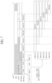
- FIG. 7 is a timing diagram illustrating a data format of the input data packet generated by the micro controller unit shown in FIG. 2 and a detailed operation of the control circuit;
- FIG. 8 is a diagram illustrating a method for each of the dimming control devices shown in FIG. 1 to calculate identification information (ID) thereof;
- FIG. 9 is a schematic diagram for describing a hybrid dimming control according to one embodiment of the present disclosure.
- FIG. 10 a diagram illustrating an operation timing of a dimming control circuit according to one embodiment of the present disclosure.
- FIG. 11 is a flowchart illustrating a method for controlling backlight unit according to one embodiment of the present disclosure.
- temporal relationship for example, when a temporal relationship is described as “after,” “subsequently to,” “next,” “before,” and the like, a non-consecutive case may be included unless the term “immediately” or “directly” is used in the expression.
- first the terms “first,” “second,” and the like may be used herein to describe various components, the components are not limited by the terms. These terms are used only to distinguish one component from another component. Therefore, a first component described below may be a second component within the technical spirit of the present disclosure.
- the meaning of “at least one of a first item, a second item, and a third item” may mean a combination of all items that can be presented from two or more of the first item, the second item and the third item as well as each of the first item, the second item or the third item.
- FIG. 1 is a diagram exemplarily illustrating a system for controlling backlight unit according to one embodiment of the present disclosure.
- the system for controlling backlight unit 100 (hereinafter, referred to as “backlight unit control system”) includes a dimming data generation circuit 110 , a micro controller unit 102 , boards 3001 to 3012 on which a plurality of dimming control devices 301 to 340 and 401 to 440 are mounted, and a gate control signal generation circuit 150 .
- each of the micro controller unit 102 , the dimming control devices 301 to 340 and 401 to 440 , and the gate control signal generation circuit 150 may be a semiconductor integrated circuit, a semiconductor chip, or a package in which a semiconductor integrated circuit (or the semiconductor chip) is packaged.
- the backlight unit control system 100 may be used for controlling dimming of a display device or television (TV) that includes a backlight unit (BLU).
- the display device may be a thin-film-transistor liquid-crystal display (TFT-LCD) device or an LED display device.
- TFT-LCD thin-film-transistor liquid-crystal display
- a display panel included in the display device may be divided into a plurality of regions (e.g., 12 regions), and the plurality of boards 3001 to 3012 may be arranged to correspond to the respective regions of the display panel as shown in FIG. 1 .
- Each of the boards 3001 to 3012 may be a printed circuit board (PCB).
- the plurality of dimming control devices 301 to 340 are mounted on each of the boards 3001 to 3006 , and the plurality of dimming control devices 401 to 440 are mounted on each of the boards 3007 to 3012 .
- the dimming control devices 301 to 340 and 401 to 440 mounted on each of the boards 3001 to 3012 may constitute a dimming control device group. That is, when the backlight unit control system 100 includes K dimming control device groups, the backlight unit control system 100 includes K boards, and one dimming control device group is mounted for each board.
- first dimming control device group mounted on the first board 3001 may include 40 dimming control devices 301 to 340 .
- p (e.g., two) dimming control devices may be disposed for each row of each of the boards 3001 to 3012 .
- two dimming control devices may be disposed in each row of each board 3001 to 3012 .
- the dimming control devices 301 to 340 may be disposed in a form of an m*p matrix in each of the boards 3001 to 3006 and the dimming control devices 401 to 440 may be disposed in the form of the m*p matrix in each of the boards 3007 to 3012 , wherein m may be 20 and p may be 2.
- a plurality of light sources (not shown) to be controlled may be installed on each of the boards 3001 to 3012 so as to be electrically connected to the dimming control devices 301 to 340 and 401 to 440 , respectively.
- Each of the dimming control devices 301 to 340 and 401 to 440 may control dimming of a predetermined number of light sources (e.g., six light sources).
- the light source may be a Light Emitting Diode (LED) or an organic LED (OLED).
- the boards 3001 to 3006 disposed at an upper end region will be referred to as a first board group and the boards 3007 to 3012 disposed at a lower end region will be referred to as a second board group.
- the first board group and the second board group may each consist of K/2 boards.
- Each of the dimming control devices 301 and 302 disposed in a first row of each of the boards 3001 to 3006 of the first board group is commonly connected to a first gate line G 1
- each of the dimming control devices 303 and 304 disposed in a second row of each of the boards 3001 to 3006 of the first board group is commonly connected to a second gate line G 2
- each of the dimming control devices 339 and 340 disposed in a 20-th row of each of the boards 3001 to 3006 of the first board group is commonly connected to a 20-th gate line G 20 .
- Each of the dimming control devices 401 and 402 disposed in a first row of each of the boards 3007 to 3012 of the second board group is commonly connected to a 21-st gate line G 21
- each of the dimming control devices 403 and 404 disposed in a second row of each of the boards 3007 to 3012 of the second board group is commonly connected to a 22-nd gate line G 22
- each of the dimming control devices 439 and 440 disposed in a 20-th row of each of the boards 3007 to 3012 of the second board group is commonly connected to a 40-th gate line G 40 .
- each of the dimming control devices 301 to 340 mounted on each of the boards 3001 to 3006 and the dimming control devices 401 to 440 mounted on each of the boards 3007 to 3012 receives an input data packet including dimming data from the micro controller unit 102 , dimming information corresponding to the dimming data is directly displayed through the light sources, which are controlled by the respective dimming control devices 301 to 340 and 401 to 440 , by a corresponding gate control signal transmitted through the corresponding gate line. Accordingly, a variation between an image processed by the display device and the dimming information processed by the backlight unit control system 100 is less than one frame.
- each of the dimming control devices 301 to 340 and 401 to 440 connected to the gate lines G 1 to G 40 simultaneously operates according to the gate control signal G[1] to G[40] transmitted through each of the gate lines G 1 to G 40 , each of the dimming control devices 301 to 340 and 401 to 440 controls local dimming of a region managed by itself.
- the gate control signals G[1] to G[40] transmitted through the gate lines G 1 to G 40 are sequentially generated and do not overlap each other.
- the backlight unit control system 100 Since the backlight unit control system 100 performs local dimming for the light sources in units of gate lines, the backlight unit control system 100 according to the present disclosure has an effect of preventing a mismatch between the image and the local dimming as compared to a conventional dimming control technique in which local dimming is performed in units of frames.
- the boards 3001 and 3007 disposed in a first column are commonly connected to a first packet generator 230 - 1 of the micro controller unit 102
- the boards 3002 and 3008 disposed in a second column are commonly connected to a second packet generator 230 - 2 of the micro controller unit 102
- the boards 3006 and 3012 disposed in a sixth column are commonly connected to a sixth packet generator 230 - 6 of the micro controller unit 102 .
- the micro controller unit 102 may control an operation of the dimming control device 301 using a first gate control signal G[1] transmitted through the first gate line G 1 and may control an operation of the dimming control device 401 using a 21-st gate control signal G[21]transmitted through the 21-st gate line G 21 .
- Identification information (which is referred to as “ID”) that may uniquely identify an i-th dimming control device disposed on each of the boards 3001 to 3012 is identical to each other.
- i is a natural number and satisfies 1 ⁇ i ⁇ 40.
- the ID of the dimming control device 301 firstly disposed on each of the boards 3001 to 3006 and the ID of the dimming control device 401 firstly disposed on each of the boards 3007 to 3012 are identical to each other, and the ID of the dimming control device 340 lastly disposed on each of the boards 3001 to 3006 and the ID of the dimming control device 440 lastly disposed on each of the boards 3007 to 3012 are identical to each other.
- the dimming data generation circuit 110 receives video data VDATA corresponding to RBG values from the outside, analyzes the video data VDATA, generates dimming data DI according to the analysis result, and outputs the dimming data DI to the controller 210 of the micro controller unit 102 .
- the micro controller unit 102 generates an input data packet SDI 1 to SDI 6 based on a serial peripheral interface (SPI) communication protocol based on the dimming data DI.
- the micro controller unit 102 includes a controller 210 and a plurality of packet generators 230 - 1 to 230 - 6 .
- FIG. 1 it is illustrated that the micro controller unit 102 includes six packet generators 230 - 1 to 230 - 6 , but this is merely one example, and the micro controller unit 102 may also include five or less packet generators or seven or more packet generators.
- each of the packet generators 230 - 1 to 230 - 6 outputs the input data packets SDI 1 to SDI 6 to the firstly disposed dimming control device 301 and 401 among the plurality of dimming control devices 301 to 340 , which are mounted on each of the boards 3001 to 3006 in a daisy-chain manner, and the plurality of dimming control devices 401 to 440 , which are mounted on each of the boards 3007 to 3012 in a daisy-chain manner.
- the data formats of each input data packet SDI 1 to SDI 6 may be the same, and thus, the operation of each of the dimming control devices processing each input data packet SDI 1 to SDI 6 is almost same.
- one micro controller unit 102 may be connected in a daisy-chain manner to the plurality of dimming control devices 301 to 340 and 401 to 440 , the number of channels for connecting between the micro controller unit 102 and the dimming control devices 301 to 340 and 401 to 440 is reduced, and a time for transmitting the input data packet SDI 1 to SDI 6 is reduced, so that a data processing speed is increased. In addition, the time for transmitting the input data packet SDI 1 to SDI 6 is reduced, and a timing margin is enhanced, so that a large number of dimming control devices 301 to 340 and 401 to 440 may be connected in a daisy-chain manner to one micro controller unit 102 .
- FIG. 2 is a block diagram schematically illustrating a configuration of the micro controller unit shown in FIG. 1
- FIG. 3 is a diagram exemplarily illustrating a data format of each of the input data packet generated by the micro controller unit of FIG. 2 and the output data packet generated by delaying the input data packet by one bit.
- the micro controller unit 102 to which the plurality of dimming control devices 301 to 340 and 401 to 440 are connected in a daisy-chain manner includes a controller 210 and a packet generator 230 - 1 to 230 - 6 .
- a first packet generator 230 - 1 connected with a connector 3101 of the board 3001 and a connector 3107 of the board 3007 is illustrated.
- the controller 210 receives dimming data from the dimming data generation circuit 110 .
- the controller 210 determines bits to be included in the input data packet SDI 1 based on the dimming data so that the first packet generator 230 - 1 may generate the input data packet SDI 1 . Additionally, the controller 210 generates a selection signal SEL and a gate control signal GCS for controlling the gate lines G 1 to G 40 , and provides the selection signal SEL and the gate control signal GCS to the gate control signal generation circuit 150 .
- the controller 210 determines bits constituting first data FDATA, bits constituting second data IDATA, and bits constituting dimming data DATA, which are to be included in the input data packet SDI 1 .
- the first data FDATA includes bits for enabling a specific dimming control device to determine by itself which dimming control device it is from among the plurality of dimming control devices 301 to 340 and 401 to 440 .
- each of the dimming control devices 301 to 340 and 401 to 440 may set identification information (ID) thereof (hereinafter, referred to as “first ID”) using the bits included in the first data FDATA.
- ID identification information
- a most significant bit among the bits included in the first data FDATA has a value of “1,” and the first data FDATA may have a value of 80 (hex).
- hex refers to hexadecimal.
- the second data IDATA includes bits representing unique information (hereinafter referred to as “second ID”) specifying the dimming control device, which needs to process the dimming data DATA, among the plurality of dimming control devices 301 to 340 and 401 to 440 .
- second ID unique information
- the dimming data DATA includes bits for controlling the local dimming of the light sources.
- the controller 210 may further determine bits to be included in first dummy data DDATA indicating the number of the plurality of dimming control devices 301 to 340 and 401 to 440 . In one embodiment, the controller 210 may set all values of the bits to be included in the first dummy data DDATA to “0”.
- the controller 210 further determines the bits of the first dummy data DDATA, which indicates the number of the plurality of dimming control devices 301 to 340 and 401 to 440 , because although each of the plurality of dimming control devices 301 to 340 and 401 to 440 should receive all the dimming data DATA included in the input data packet SDI while a chip selection signal CSn is maintained at a low level, the chip selection signal CSn may transition to a high level in a state in which last dimming control devices 340 and 440 do not receive all of the dimming data DADA since the input data packet SDI output from the micro controller unit 102 is delayed by one bit while passing through each of the plurality of dimming control devices 301 to 340 and 401 to 440 , and thus, the last dimming control devices 340 and 440 may not receive some of the dimming data DATA.
- the controller 210 may additionally determine a bit to be included in second dummy data D.
- the second dummy data D means one dummy bit that is set to safely receive the output data packet SDO before the chip selection signal CSn ends. In one embodiment, one bit of the second dummy data D may be set to “0.”
- the first packet generator 230 - 1 generates the input data packet SDI by arranging the bits determined by the controller 210 according to a serial peripheral interface (SPI) communication protocol.
- SPI serial peripheral interface
- the first packet generator 230 - 1 outputs the generated input data packet SDI to the first dimming control device 301 among the plurality of dimming control devices 301 to 340 and the first dimming control device 401 among the plurality of dimming control devices 401 to 440 connected thereto in a daisy-chain manner.
- the first packet generator 230 - 1 may output the input data packet SDI to the first dimming control devices 301 and 401 together with the chip selection signal CSn, a serial clock signal SCK, and a pulse width modulation (PWM) clock signal PCLK for dimming control.
- PWM pulse width modulation
- the chip selection signal CSn refers to a signal for selecting the dimming control device to be operated among the plurality of dimming control devices 301 to 340 and 401 to 440
- the serial clock signal SCK refers to a clock signal used by each of the dimming control devices 301 to 340 and 401 to 440 to process the first ID, the second ID, and the dimming data
- the PWM clock signal PCLK refers to a clock signal used to generate a PWM signal for controlling dimming of the light sources.
- FIG. 3 illustrates an example of the first input data packet SDI 1 transmitted to the 40 dimming control devices 301 to 340 mounted on the first board 3001 by the first packet generator 230 - 1 .
- the first input data packet SDI 1 will be described as the input data packet SDI.
- the input data packet SDI includes a plurality of data packets D 1 to D 40 .
- an i-th data packet Di included in the input data packet SDI is a data packet for adjusting brightness of six light sources connected to the i-th dimming control device.
- a first data packet D 1 is a data packet for adjusting brightness of the six light sources connected to a first dimming control device 301
- a second data packet D 2 is a data packet for adjusting brightness of the six light sources connected to a second dimming control device 302
- a 40-th data packet D 40 is a data packet for adjusting brightness of the six light sources connected to a 40-th dimming control device 340 .
- first dimming data DATA 1 included in the first data packet SDI_D 1 is dimming data for adjusting dimming of a first light source among the six light sources
- second dimming data DATA 2 is dimming data for adjusting dimming of a second light source among the six light sources
- sixth dimming data DATA 6 is dimming data for adjusting dimming of a sixth light source among the six light sources.
- the six light sources may be connected to each dimming control device through connection pins (not shown), and each dimming control device controls each of the six light sources using the first to sixth dimming data DATA 1 to DATA 6 by supplying the corresponding dimming data to the connection pin that is determined in advance according to the order in which the first to sixth dimming data DATA 1 to DATA 6 included in the first data packet SDI_D 1 are received.
- the first data packet SDI_D 1 is illustrated as including six pieces of dimming data DATA 1 to DATA 6 because it is assumed that the first dimming control device 301 controls six light sources, but when the dimming control device 301 controls T light sources (where T is a natural number greater than or equal to 2), T pieces of dimming data DATA 1 to DATAT are included in the first data packet SDI_D 1 .
- the first data packet SDI_D 1 which is input to the first dimming control device 301 , may include a command field C_F and a data field D_F.
- the command field C_F may include the first data FDATA and the second data IDATA
- the data field D_F may include the dimming data DATA.
- the data field D_F may further include the first dummy data DDATA and the second dummy data D.
- the first dimming control device 301 delays the first data packet SDI_D 1 by one-bit and outputs the delayed first data packet SDO_D 1 to the second dimming control device 302 .
- the description of the data format of the second to the 40-th data packets D 2 to D 40 will be omitted.
- the packet generator 230 - 1 receives the output data packet SDO from the 40-th dimming control devices 340 which is the last dimming control device among the plurality of dimming control devices 301 to 340 and the 40-th dimming control devices 440 which is the last dimming control device among the plurality of dimming control devices 401 to 440 , and transmits the received output data packet SDO to the controller 210 .
- the controller 210 may check whether the input data packet SDI is normally transmitted to the plurality of dimming control devices 301 to 340 and 401 to 440 by calculating delayed bits of the received output data packet SDO.
- the gate control signal generation circuit 150 may generate gate control signals G[1] to G[40] in response to a gate control signal GCS and selection signals SEL, which are output from the controller 210 .
- the gate control signal generation circuit 150 may generate gate control signals G[1] to G[20] having timings as shown in FIG. 3 .
- the gate control signals G[1] to G[20] for a first gate line G 1 to a 20-th gate line G 20 are shown in FIG. 3 .
- the gate control signal generation circuit 150 generates the first gate control signal G[1] in the form of a pulse after two data packets D 1 and D 2 are supplied to two dimming control devices 301 and 302 , generates a second gate control signal G[2] in the form of a pulse after two data packets D 3 and D 4 are supplied to two dimming control devices 303 and 304 , and generates a 20-th gate control signal G[20] in the form of a pulse after two data packets D 39 and D 40 are supplied to two dimming control devices 339 and 340 .
- the gate control signal generation circuit 150 may include a demultiplexer.
- the demultiplexer may generate the gate control signals G[1] to G[20] having the timings shown in FIG. 3 in response to the gate control signal GCS input to an input terminal thereof and the selection signals SEL input to selection terminals.
- the first gate control signal G[1] is supplied to the first gate line G 1
- the 20-th gate control signal G[20] is supplied to the 20-th gate line G 20 .
- the plurality of dimming control devices 301 to 340 and 401 to 440 control local dimming of the plurality of light sources respectively connected to the corresponding dimming control devices using the input data packets SDI 1 to SDI 6 received from the micro controller unit 102 .
- the plurality of dimming control devices 301 to 340 and 401 to 440 may be connected to the micro controller unit 102 in a daisy-chain manner.
- the first dimming control devices 301 and 401 are connected to the micro controller unit 102 and receive the input data packet SDI from the micro controller unit 102 .
- the first dimming control devices 301 and 401 generate an output data packet SDO delayed by one bit from the received input data packet SDI and output the output data packet SDO to the second dimming control devices 302 and 402 .
- the second dimming control devices 302 and 402 use the output data packet SDO output from the first dimming control devices 301 and 401 as the input data packet SDI and delays the input data packet SDI again by one bit to generate the output data packet SDO, and output the output data packet SDO to the third dimming control devices 303 and 403 .
- the dimming control devices 301 to 340 and 401 to 440 output the input data packet SDI by delaying the input data packet SDI only by one bit, even when each of the boards 3001 to 3012 includes 40 dimming control devices 301 to 340 and 401 to 440 , a total delay occurs only by 40-bits and thus a dimming data transmission time is reduced, so that the number of the dimming control devices connectable to the micro controller unit 102 may be increased.
- FIG. 4 is a timing diagram for describing the dimming control devices shown in FIG. 1 and an operation of each of the dimming control devices. It is assumed that the structure and operation method of each dimming control device are the same, and hereinafter, for convenience of description, descriptions are made based on operations of first to third dimming control devices 301 to 303 and a reference number for the packet generator will be marked as 230 .
- the micro controller unit 102 transmits the chip selection signal CSn, the serial clock signal SCK, and the PWM clock signal PCLK to the first to third dimming control devices 301 to 303 connected in a daisy-chain manner to the packet generator 230 .
- the micro controller unit 102 transmits a master output slave input MOSI to the first dimming control device 301 connected to the packet generator 230 .
- the micro controller unit 102 receives a master input slave output MISO, which is output from the 40-th dimming control device 340 , through the packet generator 230 .
- the master output slave input MOSI refers to the input data packet SDI transmitted to the first dimming control device 301
- the master input slave output MISO refers to the output data packet SDO transmitted from the 40-th dimming control device 340 .
- the first dimming control device 301 includes a D-flip-flop circuit 510 and a control circuit 520 .
- the D-flip-flop circuit 510 captures the input data packet SDI at a second edge (e.g., a falling edge) of the serial clock signal SCK to output the output data packet SDO.
- a second edge e.g., a falling edge
- a setup timing margin is improved as the D-flip-flop circuit 510 that responds to a falling edge is used.
- the D-flip-flop circuit 510 outputs the output data packet SDO generated by delaying the input data packet SDI by one bit (also referred to as a one-bit time) to the second dimming control device 302 .
- the control circuit 520 performs a count operation in response to a first edge (e.g., a rising edge) of the serial clock signal SCK, and determines the first ID using a count value at the time at which a bit firstly having a value of “1” among the bits included in the first data FDATA is input.
- the control circuit 520 compares the determined first ID with the second ID included in the second data IDATA, and controls the light source L 1 connected to the first dimming control device 301 using the dimming data DATA when the first ID and the second ID match and passes the dimming data DATA when the first ID and the second ID do not match.
- the first dimming control device 301 sets ID DID 1 thereof to 1 (dec).
- “bin” refers to binary
- “dec” refers to decimal.
- the second dimming control device 302 which receives the output data packet SDO delayed by one bit by the D-flip-flop circuit 510 of the first dimming control device 301 as the input data packet SDI, sets ID DID 2 thereof to 2 (dec) when the count value CNT 1 at the time at which the bit firstly having a value of “1” among the bits included in the first data FDATA of the input data packet SDI is input, is 1 (dec) and the initial count value is 0 (dec).
- the third dimming control device 303 which receives the output data packet SDO delayed by one bit by the D-flip-flop circuit of the second dimming control device 302 as the input data packet SDI, sets ID DID 3 thereof to 3 (dec) when the count value CNT 1 at the time at which the bit firstly having a value of “1” among the bits included in the first data FDATA of the input data packet SDI is input, is 2 (dec) and the initial count value is 0 (dec).
- Each of the dimming control devices 301 to 340 and 401 to 440 determines ID DIDi thereof using a timing when the count value CNT 1 at the time at which the bit firstly having a value of “1” among the bits included in the first data FDATA of the input data packet SDI is input, is detected and the initial count value
- each of the dimming control devices 301 to 340 and 401 to 440 captures the input data packet SDI at the second edge of the serial clock signal SCK to output the output data packet SDO, 40-bits delay is generated between the input data packet SDI of the first dimming control devices 301 and 401 and the output data packet SDO of the 40-th dimming control devices 340 and 340 .
- FIG. 5 is a block diagram of the control circuit shown in FIG. 4
- FIG. 6 is a diagram illustrating an implementation example of the control circuit shown in FIG. 5
- FIG. 7 is a timing diagram illustrating a data format of the input data packet generated by the micro controller unit shown in FIG. 2 and a detailed operation of the control circuit.
- the control circuit 520 includes a first-ID processing circuit 530 , a second-ID processing circuit 540 , a comparison circuit 550 , a dimming-data processing circuit 560 , a selection circuit 570 , and a dimming control circuit 580 .
- the first-ID processing circuit 530 performs a first count operation in response to a first edge of the serial clock signal SCK.
- the first-ID processing circuit 530 outputs a count value at the time at which the bit firstly having a value of “1” among the bits included in the first data FDATA is input, as a first count value CNT 1 .
- the first-ID processing circuit 530 determines first ID DID 1 of the first dimming control device 301 using the first count value CNT 1 or the first count value CNT 1 and an initial count value, and stores the first ID DID 1 .
- the first-ID processing circuit 530 may include a first counter 531 , an ID determination circuit 533 , and a first register 535 .
- the first counter 531 is reset in response to a transition of the chip selection signal CSn from a high level to a low level, and performs the first count operation in response to the first edge of the serial clock signal SCK.
- the first counter 531 outputs the count value at the time at which the bit firstly having a value of “1” among the bits included in the first data FDATA is input, as the first count value CNT 1 .
- the ID determination circuit 533 uses the first count value CNT 1 or the first count value CNT 1 and the initial count value to determine the first ID DID 1 .
- the first count value CNT 1 shown in FIG. 7 illustrates output values of the first counter included in each of the 40 dimming control devices 301 to 340 represented in time series.
- the dimming control devices 301 to 340 are implemented as 40 dimming control devices and the dimming data DATA includes six pieces of dimming data DATA 1 to DATA 6 is illustrated as an example.
- bDATA 1 to bDATA 6 refer to pieces of delayed data.
- the first count value CNT 1 of the first counter included in an i-th dimming control device among 40 dimming control devices 301 to 340 is “i ⁇ 1.”
- the first count value CNT 1 of the first counter included in the first dimming control device 301 is 0 (dec)
- the first count value CNT 1 of the first counter included in the second dimming control device 302 is 1 (dec)
- the first count value CNT 1 of the first counter included in the third dimming control device 303 is 2 (dec)
- the first count value CNT 1 of the first counter included in a 39-th dimming control device 339 is 38 (dec)
- the first count value CNT 1 of the first counter included in a 40-th dimming control device 340 is 39 (dec).
- the ID determination circuit may determine the first ID of each of the dimming control devices 301 to 340 by adding 1 (dec) to the corresponding first count value CNT 1 .
- the first ID of the first dimming control device 301 is 1 (dec) when the first count value CNT 1 of the first counter included in the first dimming control device 301 is 0 (dec)
- the first ID of the second dimming control device 302 is 2 (dec) when the first count value CNT 1 of the first counter included in the second dimming control device 302 is 1 (dec)
- the first ID of the 39-th dimming control device 339 is 39 (dec) when the first count value CNT 1 of the first counter included in the 39-th dimming control device 339 is 38 (dec)
- the first ID of the 40-th dimming control device 340 is 40 (dec) when the first count value CNT 1 of the first counter included in the 40-th dimming control device 340 is 39 (dec).
- the first ID DID 1 of the first dimming control device 301 is determined to be 1 (dec) since the first count value CNT 1 of the first counter 531 of the first dimming control device 301 is 0 (dec)
- first ID DID 40 of the 40-th dimming control device 340 is determined to be 40 (dec) since the first count value CNT 1 of the first counter of the 40-th dimming control device 340 is 39 (dec).
- the first count value CNT 1 of the first counter of the 40-th dimming control device 340 is maintained as 39 (dec).
- the corresponding first count value CNT 1 may be determined as the first ID of each of the dimming control devices 301 to 340 as it is.
- the first ID of the first dimming control device 301 is 1 (dec) when the first count value CNT 1 of the first counter included in the first dimming control device 301 is 1 (dec)
- the first ID of the second dimming control device 302 is 2 (dec) when the first count value CNT 1 of the first counter included in the second dimming control device 302 is 2 (dec)
- the first ID of the 39-th dimming control device 339 is 39 (dec) when the first count value CNT 1 of the first counter included in the 39-th dimming control device 339 is 39 (dec)
- the first ID of the 40-th dimming control device 340 is 40 (dec) when the first count value CNT 1 of the first counter included in the 40-th dimming control device 340 is 40 (dec).
- the first register 535 receives and stores the first ID DID 1 determined by the ID determination circuit 533 .
- the second-ID processing circuit 540 extracts second ID DIF 1 from the second data IDATA, and stores the second ID DIF 1 .
- the second-ID processing circuit included in each of the dimming control devices 301 to 340 extracts 00000001 (bin) or 01 (hex) included in the second data IDATA of the input data packet SDI, which is input to the respective dimming control devices 301 to 340 , as the second ID DIF 1 .
- the second-ID processing circuit 540 may include a second counter 541 , an ID detection circuit 543 , and a second register 545 .
- the second counter 541 performs a second count operation using the first edge of the serial clock signal SCK to output a second count value CNT 2 .
- the second counter 541 may be reset in response to an output signal of the ID determination circuit 533 , and may perform the second count operation using the first edge of the serial clock signal SCK, which is input after the reset, to output the second count value CNT 2 .
- the ID detection circuit 543 receives the input data packet SDI and the second count value CNT 2 , detects a start position of the second data IDATA using the second count value CNT 2 and first information, and extracts the second ID DIF 1 from the second data IDATA using the detection result.
- the first information may include timing information about a time elapsed from when the bit firstly having a value of “1” among the bits included in the first data FDATA is detected until the second data IDATA is input.
- the ID detection circuit 543 may detect the start position of the second data IDATA using the second count value CNT 2 and extract the second ID DIF 1 from the second data IDATA using the detection result.
- the second register 545 receives and stores the second ID DIF 1 output from the ID detection circuit 543 .
- the comparison circuit 550 compares the first ID DID 1 and the second ID DIF 1 .
- the comparison circuit 550 may compare the first ID DID 1 and the second ID DIF 1 in units of bits to generate a comparison signal COMP.
- K is a natural number greater than or equal to two.
- the comparison circuit 550 Since the first ID DID 1 stored in the first register 535 of the first dimming control device 301 among the dimming control devices 301 to 340 is 00000001 (bin), and the second ID DIF 1 stored in the second register 545 of the first dimming control device 301 is 00000001 (bin), the comparison circuit 550 outputs the comparison signal COMP having a high level.
- the comparison circuit 550 of the i-th dimming control device outputs the comparison signal having a low level.
- the comparison circuit of the second dimming control device 302 or the third dimming control device 303 outputs the comparison signal having a low level.
- the dimming-data processing circuit 560 extracts the dimming data DATA from the input data packet SDI and stores the dimming data DATA. To this end, as shown in FIG. 6 , the dimming-data processing circuit 560 may include a dimming-data extraction circuit 561 and a third register 563 .
- the dimming-data extraction circuit 561 receives the input data packet SDI and the second count value CNT 2 , detects a start position of the dimming data DATA using the second count value CNT 2 and second information, and extracts the dimming data DATA using the detection result.
- the second information may include timing information about a time elapsed from when the bit firstly having a value of “1” among the bits included in the first data FDATA is detected until the dimming data DATA is input.
- the dimming-data extraction circuit 561 may detect the start position of the dimming data DATA using the second count value CNT 2 and extract the dimming data DATA using the detection result.
- the third register 563 receives and stores the dimming data DATA output from the dimming-data extraction circuit 561 .
- Each of the first to third registers 535 , 545 , and 563 is an example of a data storage device.
- the selection circuit 570 outputs one of dummy data corresponding to a first voltage (e.g., the ground voltage) input through a first input terminal thereof and the dimming data DATA input through a second input terminal thereof to the dimming control circuit 580 .
- a first voltage e.g., the ground voltage
- the selection circuit 570 may be replaced with a switch that outputs the dimming data DATA output from the third register 563 to the dimming control circuit 580 in response to the comparison signal COMP having a high level output from the comparison circuit 550 .
- the dimming control circuit 580 controls dimming of a light source L 1 based on the dimming data DATA output from the selection circuit 570 .
- the dimming control circuit 580 may control the dimming of the light source L 1 by the PWM driving method.
- the dimming control circuit 580 may control the dimming of the light source L 1 by the linear driving method using an analog signal generated based on the dimming data DATA.
- the dimming control circuit 580 may analyze a grayscale value of the dimming data DATA and perform a hybrid dimming control for controlling the dimming of the light source L 1 by selecting one of a PWM driving method or a linear driving method according to the grayscale value. Specifically, the dimming control circuit 580 may control the dimming of the light source L 1 by the PWM driving method when the dimming data DATA is low-grayscale data, and control the dimming of the light source L 1 by the linear driving method when the dimming data DATA is high-grayscale data.
- FIG. 9 conceptually illustrates a method in which the dimming control circuit 580 according to the present disclosure controls the dimming of the light source L 1 by a hybrid dimming control method.
- the dimming control circuit 580 determines that the dimming data DATA is the low-grayscale data and adjusts the dimming (or brightness) of the light source L 1 by the PWM driving method.
- the dimming control circuit 580 determines that the dimming data DATA is the high-grayscale data, and adjusts the dimming (or brightness) of the light source L 1 by the linear driving method.
- the dimming control circuit 580 may determine whether the dimming data DATA is the low-grayscale data or high-grayscale data by determining whether at least one bit having a value of “1” is present in the third bit group MBIT of the dimming data DATA.
- the dimming control circuit 580 determines that the dimming data DATA is the low-grayscale data, the dimming control circuit 580 controls the dimming of the light source L 1 by the PWM driving method using the first bit group UBIT among the dimming data DATA.
- the dimming control circuit 580 determines that the dimming data DATA is the high-grayscale data, the dimming control circuit 580 controls the dimming of the light source L 1 using an analog signal generated using both the third bit group MBIT and the second bit group LBIT among the dimming data DATA.
- the dimming control circuit 580 may include an analysis circuit 581 , a PWM dimming control circuit 583 , and a linear dimming control circuit 589 .
- the analysis circuit 581 analyzes the dimming data DATA to determine whether the dimming data DATA is the low-grayscale data or high-grayscale data. Specifically, the analysis circuit 581 may determine whether the dimming data DATA is the low-grayscale data or high-grayscale data by determining whether at least one bit having a value of “1” is present in the third bit group MBIT of the dimming data DATA.
- the light source L 1 may include an LED connected between a power line, through which an operating voltage VDD is supplied, and a first connection terminal CP 1 and a resistor ER connected between a second connection terminal CP 2 and the ground GND.
- the resistor ER serves to adjust a current I CH flowing through a current path formed by the operating voltage VDD, transistors 587 and 593 , and the resistor ER.
- the PWM dimming control circuit 583 includes a PWM signal generator 585 and a first transistor 587 .
- the PWM signal generator 585 may additionally use a first gate control signal G[1] to generate the PWM signal.
- the linear dimming control circuit 589 controls the dimming of the light source L 1 using an analog signal DOUT generated using the reference data of 000000111111 (bin).
- the linear dimming control circuit 589 includes a digital-to-analog converter DAC, a switch SW, a capacitor CS, an amplifier circuit 591 , and a second transistor 593 .
- Each of the transistors 587 and 593 may be a power field-effect transistor (FET) and may be an n-type metal oxide semiconductor FET (nMOSFET).
- the digital-to-analog converter DAC converts the reference data of 000000111111 (bin) output from the analysis circuit 581 into an analog signal.
- the switch SW controls a connection between an output terminal of the digital-to-analog converter DAC and a first input terminal (e.g., a (+) input terminal) of the amplifier circuit 591 in response to the first gate control signal G[1].
- a first input terminal e.g., a (+) input terminal
- the capacitor CS is connected between the first input terminal of the amplifier circuit 591 and the ground and charges electric charges corresponding to the analog signal corresponding to the reference data of 000000111111 (bin).
- a second input terminal (e.g., ( ⁇ ) input terminal) of the amplifier circuit 591 is connected to an output terminal of the amplifier circuit 591 , amplifies a difference between a voltage charged in the capacitor CS and an output voltage of the amplifier circuit 591 , and outputs the amplified result to a control terminal (e.g., a gate) of the second transistor 593 .
- the second transistor 593 controls a connection between the intermediate node ND and the second connection terminal CP 2 in response to the output signal of the amplifier circuit 591 .
- the linear dimming control circuit 589 controls the dimming of the light source L 1 using an analog signal corresponding to the data of 00001000001 (bin) including the third bit group MBIT and the second bit group LBIT among the dimming data DATA.
- the digital-to-analog converter DAC converts the data of 00001000001 (bin) including the third bit group MBIT and the second bit group LBIT into an analog signal.
- the switch SW which is turned on in response to the first gate control signal G[1], outputs the analog signal DOUT of the digital-to-analog converter DAC to the first input terminal of the amplifier circuit 591 , so that the capacitor CS charges electric charges corresponding to the analog signal DOUT.
- the amplifier circuit 591 amplifies the difference between the voltage charged in the capacitor CS and the output voltage of the amplifier circuit 591 and outputs the amplified result to the control terminal of the second transistor 593 . Accordingly, the second transistor 593 adjusts the amount of the current I CH flowing through the second transistor 593 in response to the signal corresponding to the data of 00001000001 (bin), so that the dimming of the LED included in the light source L 1 is adjusted.
- FIG. 11 is a flowchart illustrating a dimming control method according to one embodiment of the present disclosure. Since the plurality of gate lines G 1 to G 40 according to the present disclosure operate in a row sequential driving method, the dimming control method according to the present disclosure may be equally applied to all gate lines G 1 to G 40 . Thus, the dimming control method according to the present disclosure will be described below with reference to the first and second dimming control devices 301 and 302 connected to the first gate line G 1 .
- first data packet D 1 is a data packet containing first dimming data to be processed by the first dimming control device 301
- second data packet D 2 is a data packet containing second dimming data to be processed by the second dimming control device 302 .
- the first dimming control device 301 connected to the micro controller unit 102 sequentially receives the first and second data packets D 1 and D 2 from the micro controller unit 102 according to a timing of the chip selection signal CSn (S 110 ).
- the first dimming control device 301 receives the first data packet D 1 when a level of the chip selection signal CSn transitions from a high level to a low level, the first dimming control device 301 waits until the level of the chip selection signal CSn transitions from the high level to a low level when the level of the chip selection signal CSn transitions from the low level to the high level.
- the first dimming control device 301 receives the second data packet D 2 when a level of the chip selection signal CSn again transitions from the high level to the low level, and the first dimming control device 301 waits until the level of the chip selection signal CSn transitions from the high level to a low level when the level of the chip selection signal CSn again transitions from the low level to the high level.
- the first dimming control device 301 sequentially transmits the first and second data packets D 1 and D 2 to the second dimming control device 302 by delaying the first and second data packets D 1 and D 2 by one-bit (S 112 ).
- the first dimming control device 301 may delay the first and second packets D 1 and D 2 by one-bit using a D-flip-flop included therein.
- the first and second dimming control devices 301 and 302 determine a first ID which is their ID for each of the first and second data packets D 1 and D 2 , respectively (S 114 ). Specifically, the first and second dimming control devices 301 and 302 may determine the first ID using a count value at the time at which a bit firstly having a value of “1” among the bits included in the first data FDATA of each of the first data packet D 1 and the second packet D 2 is input whenever the first and second data packets D 1 and D 2 are input.
- the first and second dimming control devices 301 and 302 extracts the second ID for each of the first and second data packets D 1 and D 2 , respectively (S 116 ), and then compare the first ID and the second ID for each of the first and second data packets D 1 and D 2 (S 118 ). At this time, the first and second data packets D 1 and D 2 may be extracted from a second data IDATA of the first and second data packets D 1 and D 2 , respectively.
- the first dimming control device 301 stores the first dimming data included in the first data packet D 1 when the first ID and the second ID, which are obtained in the first data packet D 1 , match, and the second dimming control device 302 stores the second dimming data included in the second data packet D 2 when the first ID and the second ID, which are obtained in the second data packet D 2 , match (S 120 ).
- the first dimming control device 301 passes the second dimming data included in the second data packet D 2 because the first ID and the second ID, which are obtained in the second data packet D 2 , do not match
- the second dimming control device 302 passes the first dimming data included in the first data packet D 1 because the first ID and the second ID, which are obtained in the first data packet D 1 , do no match (S 122 ).
- the first dimming control device 301 controls dimming of the light source L 1 connected to the first dimming control device 301 using the stored first dimming data and the second dimming control device 302 controls dimming of the light source L 2 connected to the second dimming control device 302 using the stored second dimming data (S 126 ).
- dimming information corresponding to the dimming data is directly displayed through the light sources, which are controlled by the i dimming control devices, by a corresponding gate control signal transmitted through the corresponding gate line. Accordingly, a variation between an image processed by the display device and the dimming information processed by the backlight unit control system 100 is less than one frame.
- the methods described herein may be implemented, at least in part, using one or more computer programs or components.
- the components may be provided as a series of computer instructions on a computer readable medium or machine readable medium, including a volatile or non-volatile memory.
- the instructions may be provided as software or firmware, and may, in whole or in part, be implemented in a hardware configuration such as application-specific integrated circuits (ASICs), field-programmable gate arrays (FPGAs), digital signal processors (DSPs), or other similar devices.
- ASICs application-specific integrated circuits
- FPGAs field-programmable gate arrays
- DSPs digital signal processors
- the instructions may be configured to be executed by one or more processors or other hardware configurations, and the processor or other hardware components may perform all or part of the methods and procedures disclosed herein when executing the series of computer instructions.
- local dimming is performed on a backlight unit in units of gate lines, so that a time difference between an image displayed on a display panel and the local dimming of the backlight unit can be reduced to be less than one frame period, thereby preventing a mismatch between the image and the local dimming.
- a micro controller unit and a plurality of dimming control devices are connected in a daisy-chain manner so that the number of channels between the micro controller unit and the plurality of dimming control devices can be reduced, and a time for transmitting an input data packet to the dimming control devices from the micro controller unit decreases so that local dimming for light sources can be quickly performed and response time can improve.
- one micro controller unit is connected in a daisy-chain manner to a plurality of dimming control devices, and an output data packet of each of the dimming control devices is delayed by one bit from an input data packet, so that an overall delay time generated by the plurality of dimming control devices can be reduced, and a timing margin can be improved, thereby increasing the number of the dimming control devices connectable to one micro controller unit.
- each of dimming control devices can set ID thereof using bits included in first data of an input data packet only by transmitting the input data packet once without transmitting a separate command for setting the ID, so that each of the dimming control devices can determine by itself whether dimming data transmitted from a micro controller unit is dimming data to be processed by itself based on the set ID.
Landscapes
- Engineering & Computer Science (AREA)
- Physics & Mathematics (AREA)
- Computer Hardware Design (AREA)
- General Physics & Mathematics (AREA)
- Theoretical Computer Science (AREA)
- Chemical & Material Sciences (AREA)
- Crystallography & Structural Chemistry (AREA)
- Circuit Arrangement For Electric Light Sources In General (AREA)
Abstract
Description
Claims (18)
Applications Claiming Priority (2)
| Application Number | Priority Date | Filing Date | Title |
|---|---|---|---|
| KR10-2021-0183618 | 2021-12-21 | ||
| KR1020210183618A KR102895638B1 (en) | 2021-12-21 | 2021-12-21 | System and Method for Controlling Back Light Unit |
Publications (2)
| Publication Number | Publication Date |
|---|---|
| US20230197021A1 US20230197021A1 (en) | 2023-06-22 |
| US12051382B2 true US12051382B2 (en) | 2024-07-30 |
Family
ID=86768730
Family Applications (1)
| Application Number | Title | Priority Date | Filing Date |
|---|---|---|---|
| US18/083,032 Active 2042-12-16 US12051382B2 (en) | 2021-12-21 | 2022-12-16 | System and method for controlling back light unit |
Country Status (4)
| Country | Link |
|---|---|
| US (1) | US12051382B2 (en) |
| KR (1) | KR102895638B1 (en) |
| CN (1) | CN116312392A (en) |
| TW (1) | TW202327333A (en) |
Families Citing this family (1)
| Publication number | Priority date | Publication date | Assignee | Title |
|---|---|---|---|---|
| US12431071B2 (en) | 2023-12-04 | 2025-09-30 | Novatek Microelectronics Corp. | Operational method for memories |
Citations (4)
| Publication number | Priority date | Publication date | Assignee | Title |
|---|---|---|---|---|
| US20040207620A1 (en) * | 2003-04-21 | 2004-10-21 | Samsung Electronics Co., Ltd. | Power supply, liquid crystal display device, and method of driving the same |
| US20150102227A1 (en) * | 2013-10-14 | 2015-04-16 | Nygon As | High Throughput Detector Array |
| US20220139345A1 (en) * | 2020-10-30 | 2022-05-05 | Lg Electronics Inc. | Display device and local method of controlling local dimming thereof |
| US11615752B2 (en) * | 2020-05-07 | 2023-03-28 | Samsung Electronics Co., Ltd. | Backlight driver, backlight device including the same, and operating method of the backlight device |
Family Cites Families (4)
| Publication number | Priority date | Publication date | Assignee | Title |
|---|---|---|---|---|
| KR101285097B1 (en) * | 2009-12-31 | 2013-07-17 | 엘지디스플레이 주식회사 | Image display device and driving method thereof |
| CN111010881B (en) | 2018-08-06 | 2024-08-23 | 瑞萨设计(英国)有限公司 | Serial Communication Protocol |
| KR102663002B1 (en) | 2019-07-30 | 2024-05-09 | 삼성디스플레이 주식회사 | Display device performing local dimming |
| CN111654948B (en) * | 2020-06-12 | 2022-12-02 | 昆山龙腾光电股份有限公司 | LED driving circuit, driving method and display device |
-
2021
- 2021-12-21 KR KR1020210183618A patent/KR102895638B1/en active Active
-
2022
- 2022-12-15 CN CN202211617689.3A patent/CN116312392A/en active Pending
- 2022-12-15 TW TW111148307A patent/TW202327333A/en unknown
- 2022-12-16 US US18/083,032 patent/US12051382B2/en active Active
Patent Citations (5)
| Publication number | Priority date | Publication date | Assignee | Title |
|---|---|---|---|---|
| US20040207620A1 (en) * | 2003-04-21 | 2004-10-21 | Samsung Electronics Co., Ltd. | Power supply, liquid crystal display device, and method of driving the same |
| US20150102227A1 (en) * | 2013-10-14 | 2015-04-16 | Nygon As | High Throughput Detector Array |
| US11615752B2 (en) * | 2020-05-07 | 2023-03-28 | Samsung Electronics Co., Ltd. | Backlight driver, backlight device including the same, and operating method of the backlight device |
| US20220139345A1 (en) * | 2020-10-30 | 2022-05-05 | Lg Electronics Inc. | Display device and local method of controlling local dimming thereof |
| US11587516B2 (en) * | 2020-10-30 | 2023-02-21 | Lg Electronics Inc. | Display device and local method of controlling local dimming thereof |
Also Published As
| Publication number | Publication date |
|---|---|
| KR20230094431A (en) | 2023-06-28 |
| US20230197021A1 (en) | 2023-06-22 |
| CN116312392A (en) | 2023-06-23 |
| KR102895638B1 (en) | 2025-12-05 |
| TW202327333A (en) | 2023-07-01 |
Similar Documents
| Publication | Publication Date | Title |
|---|---|---|
| TWI549115B (en) | Emission control driver and organic light emitting display device having the same | |
| CN106297670B (en) | Emission driver and organic light-emitting display device having the same | |
| US8963811B2 (en) | LED display systems | |
| US8599117B2 (en) | Emission control driver and organic light emitting display device using the same | |
| US11765801B2 (en) | Led driver, light-emitting module, and display device for local dimming | |
| KR101479297B1 (en) | Scan driver and organic light emitting display using the same | |
| KR101056213B1 (en) | Driver and organic light emitting display device using the same | |
| US11741888B2 (en) | LED display device, driving method and chip thereof | |
| KR102648750B1 (en) | Pixel and display device including the same | |
| US12248427B2 (en) | Apparatus and method for transmitting data based on serial communication | |
| US20260031057A1 (en) | Display apparatus, control method, and adjustment method for power supply voltage | |
| KR20120028005A (en) | Emission driver and organic light emitting display using the same | |
| CN114758609A (en) | Light Emitting Diode (LED) brightness non-uniformity correction for LED display driver circuits | |
| CN115527483A (en) | Pixel circuit, control method thereof, and display device | |
| US12051382B2 (en) | System and method for controlling back light unit | |
| US12075534B2 (en) | Hybrid dimming control device and hybrid dimming control method | |
| US12073763B2 (en) | Pixel unit, display substrate and driving method thereof, and display apparatus | |
| JP2022163267A (en) | Light emitting device, display, and led display | |
| US20250140172A1 (en) | Sensing unit and display device including the same | |
| CN101551972B (en) | Display device and method of driving the same | |
| KR102925177B1 (en) | Hybrid Dimming Control Device and Hybrid Dimming Control Method | |
| US12354529B2 (en) | Pixel driving circuit and display device | |
| CN119559910B (en) | Method and system for lighting and driving LED array based on AM chip | |
| US20250308442A1 (en) | Pixel driving circuit and display device | |
| CN116682345B (en) | Display device and its source drive circuit, display system |
Legal Events
| Date | Code | Title | Description |
|---|---|---|---|
| AS | Assignment |
Owner name: LX SEMICON CO., LTD., KOREA, REPUBLIC OF Free format text: ASSIGNMENT OF ASSIGNORS INTEREST;ASSIGNORS:KIM, SANG SUK;KIM, JANG SU;SIGNING DATES FROM 20221123 TO 20221124;REEL/FRAME:062130/0064 Owner name: LX SEMICON CO., LTD., KOREA, REPUBLIC OF Free format text: ASSIGNMENT OF ASSIGNORS INTEREST;ASSIGNORS:KWAK, SOON HYEOK;KIM, JANG SU;KIM, SANG SUK;SIGNING DATES FROM 20221123 TO 20221124;REEL/FRAME:062130/0404 |
|
| FEPP | Fee payment procedure |
Free format text: ENTITY STATUS SET TO UNDISCOUNTED (ORIGINAL EVENT CODE: BIG.); ENTITY STATUS OF PATENT OWNER: LARGE ENTITY |
|
| STPP | Information on status: patent application and granting procedure in general |
Free format text: DOCKETED NEW CASE - READY FOR EXAMINATION |
|
| STPP | Information on status: patent application and granting procedure in general |
Free format text: NON FINAL ACTION MAILED |
|
| STPP | Information on status: patent application and granting procedure in general |
Free format text: RESPONSE TO NON-FINAL OFFICE ACTION ENTERED AND FORWARDED TO EXAMINER |
|
| STPP | Information on status: patent application and granting procedure in general |
Free format text: NOTICE OF ALLOWANCE MAILED -- APPLICATION RECEIVED IN OFFICE OF PUBLICATIONS |
|
| ZAAA | Notice of allowance and fees due |
Free format text: ORIGINAL CODE: NOA |
|
| ZAAB | Notice of allowance mailed |
Free format text: ORIGINAL CODE: MN/=. |
|
| STPP | Information on status: patent application and granting procedure in general |
Free format text: PUBLICATIONS -- ISSUE FEE PAYMENT VERIFIED |
|
| STCF | Information on status: patent grant |
Free format text: PATENTED CASE |