US12051204B2 - Automatic organ geometry determination - Google Patents
Automatic organ geometry determination Download PDFInfo
- Publication number
- US12051204B2 US12051204B2 US17/538,232 US202117538232A US12051204B2 US 12051204 B2 US12051204 B2 US 12051204B2 US 202117538232 A US202117538232 A US 202117538232A US 12051204 B2 US12051204 B2 US 12051204B2
- Authority
- US
- United States
- Prior art keywords
- patient
- organ
- model
- training
- pose
- Prior art date
- Legal status (The legal status is an assumption and is not a legal conclusion. Google has not performed a legal analysis and makes no representation as to the accuracy of the status listed.)
- Active, expires
Links
Images


Classifications
-
- G—PHYSICS
- G06—COMPUTING OR CALCULATING; COUNTING
- G06T—IMAGE DATA PROCESSING OR GENERATION, IN GENERAL
- G06T7/00—Image analysis
- G06T7/0002—Inspection of images, e.g. flaw detection
- G06T7/0012—Biomedical image inspection
- G06T7/0014—Biomedical image inspection using an image reference approach
-
- G—PHYSICS
- G16—INFORMATION AND COMMUNICATION TECHNOLOGY [ICT] SPECIALLY ADAPTED FOR SPECIFIC APPLICATION FIELDS
- G16H—HEALTHCARE INFORMATICS, i.e. INFORMATION AND COMMUNICATION TECHNOLOGY [ICT] SPECIALLY ADAPTED FOR THE HANDLING OR PROCESSING OF MEDICAL OR HEALTHCARE DATA
- G16H20/00—ICT specially adapted for therapies or health-improving plans, e.g. for handling prescriptions, for steering therapy or for monitoring patient compliance
- G16H20/40—ICT specially adapted for therapies or health-improving plans, e.g. for handling prescriptions, for steering therapy or for monitoring patient compliance relating to mechanical, radiation or invasive therapies, e.g. surgery, laser therapy, dialysis or acupuncture
-
- G—PHYSICS
- G06—COMPUTING OR CALCULATING; COUNTING
- G06N—COMPUTING ARRANGEMENTS BASED ON SPECIFIC COMPUTATIONAL MODELS
- G06N3/00—Computing arrangements based on biological models
- G06N3/02—Neural networks
- G06N3/04—Architecture, e.g. interconnection topology
- G06N3/045—Combinations of networks
-
- G—PHYSICS
- G06—COMPUTING OR CALCULATING; COUNTING
- G06N—COMPUTING ARRANGEMENTS BASED ON SPECIFIC COMPUTATIONAL MODELS
- G06N3/00—Computing arrangements based on biological models
- G06N3/02—Neural networks
- G06N3/08—Learning methods
-
- G—PHYSICS
- G06—COMPUTING OR CALCULATING; COUNTING
- G06N—COMPUTING ARRANGEMENTS BASED ON SPECIFIC COMPUTATIONAL MODELS
- G06N3/00—Computing arrangements based on biological models
- G06N3/02—Neural networks
- G06N3/08—Learning methods
- G06N3/084—Backpropagation, e.g. using gradient descent
-
- G—PHYSICS
- G06—COMPUTING OR CALCULATING; COUNTING
- G06T—IMAGE DATA PROCESSING OR GENERATION, IN GENERAL
- G06T7/00—Image analysis
- G06T7/50—Depth or shape recovery
-
- G—PHYSICS
- G06—COMPUTING OR CALCULATING; COUNTING
- G06T—IMAGE DATA PROCESSING OR GENERATION, IN GENERAL
- G06T7/00—Image analysis
- G06T7/70—Determining position or orientation of objects or cameras
- G06T7/73—Determining position or orientation of objects or cameras using feature-based methods
- G06T7/74—Determining position or orientation of objects or cameras using feature-based methods involving reference images or patches
-
- G—PHYSICS
- G06—COMPUTING OR CALCULATING; COUNTING
- G06T—IMAGE DATA PROCESSING OR GENERATION, IN GENERAL
- G06T7/00—Image analysis
- G06T7/70—Determining position or orientation of objects or cameras
- G06T7/73—Determining position or orientation of objects or cameras using feature-based methods
- G06T7/75—Determining position or orientation of objects or cameras using feature-based methods involving models
-
- G—PHYSICS
- G16—INFORMATION AND COMMUNICATION TECHNOLOGY [ICT] SPECIALLY ADAPTED FOR SPECIFIC APPLICATION FIELDS
- G16H—HEALTHCARE INFORMATICS, i.e. INFORMATION AND COMMUNICATION TECHNOLOGY [ICT] SPECIALLY ADAPTED FOR THE HANDLING OR PROCESSING OF MEDICAL OR HEALTHCARE DATA
- G16H30/00—ICT specially adapted for the handling or processing of medical images
- G16H30/20—ICT specially adapted for the handling or processing of medical images for handling medical images, e.g. DICOM, HL7 or PACS
-
- G—PHYSICS
- G16—INFORMATION AND COMMUNICATION TECHNOLOGY [ICT] SPECIALLY ADAPTED FOR SPECIFIC APPLICATION FIELDS
- G16H—HEALTHCARE INFORMATICS, i.e. INFORMATION AND COMMUNICATION TECHNOLOGY [ICT] SPECIALLY ADAPTED FOR THE HANDLING OR PROCESSING OF MEDICAL OR HEALTHCARE DATA
- G16H30/00—ICT specially adapted for the handling or processing of medical images
- G16H30/40—ICT specially adapted for the handling or processing of medical images for processing medical images, e.g. editing
-
- G—PHYSICS
- G16—INFORMATION AND COMMUNICATION TECHNOLOGY [ICT] SPECIALLY ADAPTED FOR SPECIFIC APPLICATION FIELDS
- G16H—HEALTHCARE INFORMATICS, i.e. INFORMATION AND COMMUNICATION TECHNOLOGY [ICT] SPECIALLY ADAPTED FOR THE HANDLING OR PROCESSING OF MEDICAL OR HEALTHCARE DATA
- G16H40/00—ICT specially adapted for the management or administration of healthcare resources or facilities; ICT specially adapted for the management or operation of medical equipment or devices
- G16H40/60—ICT specially adapted for the management or administration of healthcare resources or facilities; ICT specially adapted for the management or operation of medical equipment or devices for the operation of medical equipment or devices
- G16H40/67—ICT specially adapted for the management or administration of healthcare resources or facilities; ICT specially adapted for the management or operation of medical equipment or devices for the operation of medical equipment or devices for remote operation
-
- G—PHYSICS
- G16—INFORMATION AND COMMUNICATION TECHNOLOGY [ICT] SPECIALLY ADAPTED FOR SPECIFIC APPLICATION FIELDS
- G16H—HEALTHCARE INFORMATICS, i.e. INFORMATION AND COMMUNICATION TECHNOLOGY [ICT] SPECIALLY ADAPTED FOR THE HANDLING OR PROCESSING OF MEDICAL OR HEALTHCARE DATA
- G16H50/00—ICT specially adapted for medical diagnosis, medical simulation or medical data mining; ICT specially adapted for detecting, monitoring or modelling epidemics or pandemics
- G16H50/20—ICT specially adapted for medical diagnosis, medical simulation or medical data mining; ICT specially adapted for detecting, monitoring or modelling epidemics or pandemics for computer-aided diagnosis, e.g. based on medical expert systems
-
- G—PHYSICS
- G16—INFORMATION AND COMMUNICATION TECHNOLOGY [ICT] SPECIALLY ADAPTED FOR SPECIFIC APPLICATION FIELDS
- G16H—HEALTHCARE INFORMATICS, i.e. INFORMATION AND COMMUNICATION TECHNOLOGY [ICT] SPECIALLY ADAPTED FOR THE HANDLING OR PROCESSING OF MEDICAL OR HEALTHCARE DATA
- G16H50/00—ICT specially adapted for medical diagnosis, medical simulation or medical data mining; ICT specially adapted for detecting, monitoring or modelling epidemics or pandemics
- G16H50/50—ICT specially adapted for medical diagnosis, medical simulation or medical data mining; ICT specially adapted for detecting, monitoring or modelling epidemics or pandemics for simulation or modelling of medical disorders
-
- G—PHYSICS
- G16—INFORMATION AND COMMUNICATION TECHNOLOGY [ICT] SPECIALLY ADAPTED FOR SPECIFIC APPLICATION FIELDS
- G16H—HEALTHCARE INFORMATICS, i.e. INFORMATION AND COMMUNICATION TECHNOLOGY [ICT] SPECIALLY ADAPTED FOR THE HANDLING OR PROCESSING OF MEDICAL OR HEALTHCARE DATA
- G16H50/00—ICT specially adapted for medical diagnosis, medical simulation or medical data mining; ICT specially adapted for detecting, monitoring or modelling epidemics or pandemics
- G16H50/70—ICT specially adapted for medical diagnosis, medical simulation or medical data mining; ICT specially adapted for detecting, monitoring or modelling epidemics or pandemics for mining of medical data, e.g. analysing previous cases of other patients
-
- G—PHYSICS
- G06—COMPUTING OR CALCULATING; COUNTING
- G06T—IMAGE DATA PROCESSING OR GENERATION, IN GENERAL
- G06T2207/00—Indexing scheme for image analysis or image enhancement
- G06T2207/10—Image acquisition modality
- G06T2207/10028—Range image; Depth image; 3D point clouds
-
- G—PHYSICS
- G06—COMPUTING OR CALCULATING; COUNTING
- G06T—IMAGE DATA PROCESSING OR GENERATION, IN GENERAL
- G06T2207/00—Indexing scheme for image analysis or image enhancement
- G06T2207/20—Special algorithmic details
- G06T2207/20081—Training; Learning
-
- G—PHYSICS
- G06—COMPUTING OR CALCULATING; COUNTING
- G06T—IMAGE DATA PROCESSING OR GENERATION, IN GENERAL
- G06T2207/00—Indexing scheme for image analysis or image enhancement
- G06T2207/20—Special algorithmic details
- G06T2207/20084—Artificial neural networks [ANN]
-
- G—PHYSICS
- G06—COMPUTING OR CALCULATING; COUNTING
- G06T—IMAGE DATA PROCESSING OR GENERATION, IN GENERAL
- G06T2207/00—Indexing scheme for image analysis or image enhancement
- G06T2207/30—Subject of image; Context of image processing
- G06T2207/30004—Biomedical image processing
-
- G—PHYSICS
- G06—COMPUTING OR CALCULATING; COUNTING
- G06T—IMAGE DATA PROCESSING OR GENERATION, IN GENERAL
- G06T2207/00—Indexing scheme for image analysis or image enhancement
- G06T2207/30—Subject of image; Context of image processing
- G06T2207/30196—Human being; Person
Definitions
- Organ shape and location determination is an important aspect of clinical applications.
- Pre-operative planning and radiation therapy require precise knowledge of the physical characteristics of a target organ such as its orientation, contours, volume, etc.
- Modern medical imaging technologies provide means for obtaining such knowledge.
- a medical scan image of the organ acquired at a previous time e.g., pre-treatment
- may not reflect the characteristics of the organ at a present time e.g., during treatment.
- patients are often required to maintain a same pose or position during different medical procedures.
- additional imaging may be needed to account for changes in the patients' body shapes and/or poses.
- organ shape and/or organ location may also pose challenges for conducting comparative studies of the organ.
- medical scan images of an organ taken at different times may be inherently different in accordance with the body shape and/or pose of the patient, it may be difficult to isolate pathological changes of the organ from non-pathological changes that are caused by variations in the patient's body shape and/or pose.
- systems and methods for automatically determining the shape and/or location of an organ based on the body shape and/or pose of a patient may be highly desirable. These systems and methods may be used, for example, to facilitate treatment and pre-operative planning, improve the precision and effectiveness of surgical operations, avoid or reduce unnecessary medical scans, lower the radiation exposure of patients, enable comparative clinical studies and/or diagnosis, etc.
- An apparatus configured to perform this task may comprise one or more processors configured to receive a first model of the patient and a representation of the organ.
- the first model may indicate a body shape or pose of the patient while the representation of the organ may indicate a geometric characteristic (e.g., shape and/or location) of the organ corresponding to the body shape or pose indicated by the first model.
- the one or more processors of the apparatus may be configured to determine, using an artificial neural network (ANN), a relationship between the geometric characteristic of the organ and the body shape or pose of the patient.
- ANN artificial neural network
- Such a relationship may be represented, for example, by a plurality of parameters indicating the spatial relationship between one or more points of the organ and one or more points of the first model.
- the one or more processors of the apparatus may receive a second model of the patient indicating that at least one of the body shape or pose of the patient has changed from the body shape or pose indicated by the first model.
- the one or more processors may determine, based on the second model and the determined relationship between the organ and the body shape or pose of the patient, the geometric characteristic of the organ corresponding to the body shape or pose of the patient indicated by the second model.
- the ANN described herein may be trained to learn the relationship between the geometric characteristic (e.g., shape and/or location) of the organ and the body shape or pose of the patient based on a plurality of patient training models and a plurality of training representations of the organ. As described above, such a relationship may be reflected through a plurality of parameters that the ANN may learn during the training.
- An example training process of the ANN may include one or more of the following steps. For each of the plurality of patient training models, the ANN may obtain, from the plurality of training representations, a representation of the organ that corresponding to the body shape and/or pose of the patient represented by the patient training model. The ANN may estimate values of the plurality of parameters described above based on the training model and the representation of the organ.
- the ANN may then obtain a second training model of the patient and generate an estimated representation of the organ based on the estimated values of the plurality of parameters and the second training model.
- the ANN may then compare the estimated representation it has generated with a training representation (e.g., as a ground truth representation) of the organ that corresponds to the second patient model, and adjust the operating parameters (e.g., weights) of the ANN based on a difference (e.g., a gradient descent associated with the difference) between the ground truth representation and the representation predicted by the ANN.
- a training representation e.g., as a ground truth representation
- the operating parameters e.g., weights
- the ANN described herein may include one or more encoders and one or more decoders.
- the one or more encoders may be trained to determine the relationship (e.g., the plurality of parameters that reflects the relationship) between the geometric characteristic of the organ and the body shape or pose of the patient based on a first model of the patient and a first representation of the organ.
- the one or more decoders may be trained to construct, based on a second model of the patient and the relationship determined by the encoder, a representation of the organ corresponding to the body shape or the pose of the patient indicated by the second model.
- each of the representations of the organ described herein may comprise a point cloud (e.g., three-dimensional point cloud) that may be obtained based on at least a scan image of the organ taken when the patient is in the body shape or pose indicated by a corresponding patient model.
- a point cloud may be obtained by aligning the scan image of the organ with the corresponding patient model and determining the point cloud based on the alignment.
- each of the patient models described herein may comprise a respective parametric model of the patient, and the patient models may be generated based on respective images of the patient captured by one or more sensing devices.
- the apparatus described herein may include the one or more sensing devices.
- the techniques described herein for automatically determining the geometric characteristic of an organ based on the body shape and/or pose of the patient may be used to serve multiple clinical purposes. For example, upon determining the geometric characteristic of the organ corresponding to a second patient model (e.g., indicating a second body shape or pose of the patient), a scan image taken when the patient is in a first body shape or pose (e.g., indicated by a first patient model) may be manipulated to be aligned with the second patient model. This may not only eliminate the need for additional scans of the organ, but also allow diagnostic studies and treatment planning to be conducted in accordance with changes in the body shape and/or pose of the patient.
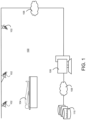
- FIG. 1 is a simplified diagram illustrating an example environment associated with one or more of the embodiments described herein.
- FIG. 2 is a simplified diagram illustrating example operations associated with the automatic determination of an organ shape and/or an organ location in accordance with one or more embodiments described herein.
- FIG. 3 is a simplified diagram illustrating the training of a neural network in accordance with one or more embodiments described herein.
- FIG. 4 is a simplified flow diagram illustrating example operations that may be associated with the training of a neural network in accordance with one or more embodiments described herein.
- FIG. 5 is a simplified diagram illustrating an example of human mesh recovery in accordance with one or more embodiments described herein.
- FIG. 6 is a block diagram illustrating example components of an apparatus that may be configured to perform the tasks described in one or more embodiments provided herein.
- FIG. 1 is a simplified diagram illustrating an example environment 100 associated with one or more of the embodiments described herein.
- Environment 100 may be part of a medical facility such as a scan room (e.g., magnetic resonance imaging (MRI), X-ray, Computed Tomography (CT), etc.) or an operating room (OR), a rehabilitation facility, a fitness center, etc.
- Environment 100 may be equipped with one or more sensing devices (e.g., 102 a, 102 b, 102 c ) such as one or more digital cameras configured to capture images (e.g., two-dimensional (2D) images) of patient 104 inside the environment 100 .
- MRI magnetic resonance imaging
- CT Computed Tomography
- OR operating room
- a rehabilitation facility e.g., a rehabilitation facility
- a fitness center e.g., a fitness center
- Sensing devices 102 a - c may be communicatively coupled to processing device 106 and/or other devices of environment 100 via communication network 108 .
- Each of sensing devices 102 a - c may include one or more sensors such as one or more 2D visual sensors (e.g., 2D cameras), one or more 3D visual sensors (e.g., 3D cameras), one or more red, green, and blue (RGB) sensors, one or more depth sensors, one or more RGB plus depth (RGB-D) sensors, one or more thermal sensors (e.g., infrared (FIR) or near-infrared (NIR) sensors), one or more radar sensors, and/or other types of image capturing devices or circuitries.
- 2D visual sensors e.g., 2D cameras
- 3D visual sensors e.g., 3D cameras
- RGB red, green, and blue
- depth sensors e.g., one or more depth sensors
- RGB plus depth sensors e.g., one or more thermal sensors
- Each of sensing devices 102 a - c may include a functional unit (e.g., a processor) configured to process the images captured by the sensing device and/or to generate (e.g., construct) a human model such as a 3D human mesh model of the patient based on the images.
- a human model may include a plurality of parameters that indicates the body shape and/or pose of the patient while the patient is inside environment 100 (e.g., during an MRI, X-ray, or CT procedure).
- the parameters may include shape parameters ⁇ and pose parameters ⁇ that may be used to determine multiple vertices (e.g., 6890 vertices based on 82 shape and pose parameters) associated with the patient's body and construct a visual representation of the patient model (e.g., a 3D mesh), for example, by connecting the vertices with edges to form polygons (e.g., such as a triangles), connecting multiple polygons to form a surface, using multiple surfaces to determine a 3D shape, and applying texture and/or shading to the surfaces and/or shapes.
- shape parameters ⁇ and pose parameters ⁇ may be used to determine multiple vertices (e.g., 6890 vertices based on 82 shape and pose parameters) associated with the patient's body and construct a visual representation of the patient model (e.g., a 3D mesh), for example, by connecting the vertices with edges to form polygons (e.g., such as a triangles), connecting multiple polygons to form
- the patient model described above may also be generated by processing unit 106 .
- processing unit 106 may be communicatively coupled to one or more of sensing devices 102 a - c and may be configured to receive images of the patient from those sensing devices (e.g., in real time or based on a predetermined schedule). Using the received images, processing unit 106 may construct the patient model, for example, in a similar manner as described above. It should be noted here that, even though processing unit 106 is shown in FIG. 1 as being separate from sensing devices 102 a - c , any one of sensing devices 102 a - c may be configured to operate as processing unit 106 (e.g., using one or more functional units or processors included in the sensing device). For example, sensing devices 102 a - c may be inter-connected via communication link 108 and exchange images with each other. One of the sensing devices may be configured to perform the model construction tasks described herein based on images received from the other sensing device(s).
- Sensing device 102 a - c or processing unit 106 may be further configured to automatically determine the geometric characteristics of an organ of the patient based on the body shape and/or pose the patient indicated by the patient model described above.
- the organ may be, for example, the spleen, liver, heart, etc. of the patient and the geometric characteristics may include, for example, the shape and/or location of the organ that corresponds to the body shape and/or pose of the patient indicated by the patient model.
- sensing device 102 a - c or processing unit 106 may be configured to automatically determine these geometric characteristics of the organ using a machine-learned model that may indicate a correlation (e.g., a spatial relationship) between the geometric characteristics of the organ and the body shape and/or pose of the patient.
- such a machine-learned model may take a patient model and a representation (e.g., a three-dimensional (3D) point cloud) of the organ as inputs and produce an output (e.g., a plurality of parameters) that indicates how the geometry (e.g., shape and/or location) of the organ may change in accordance with changes in the patient's body shape and/or pose.
- a representation e.g., a three-dimensional (3D) point cloud
- an output e.g., a plurality of parameters
- sensing device 102 a - c or processing unit 106 may determine the correlation between the geometric characteristics of the organ and the body shape and/or pose of the patient based on a first patient model and a first representation of the organ, and upon obtaining a second patient model indicating that the body shape and/or pose of the patient has changed, automatically determine the geometric characteristics of the organ that correspond to the body shape and/or pose indicated by the second patient model.
- a scan image of the organ associated with a first patient model may be manipulated to align with the second patient model.
- the aligned scan image and patient model may then be used to determine changes in the structural and/or functional state of the organ independent of potential changes in the body shape and/or pose of the patient and without additional scans of the organ.
- Having the ability to automatically determine the geometry (e.g., shape and/or location) of the organ corresponding to the second body shape and/or pose of the patient may also allow medical procedures (e.g., surgeries, radiation therapies, etc.) planned based on the first body shape and/or pose to be adapted to accommodate the changes in the patient's body shape and/or pose.
- medical procedures e.g., surgeries, radiation therapies, etc.
- Information regarding the automatically determined geometry (e.g., shape and/or location) of the organ and/or the patient models described herein may be provided in real time to a downstream application or device (e.g., such as a surgical robot).
- the information may also be saved (e.g., as metadata associated with a scan image) to a repository (e.g., database 110 shown in FIG. 1 ), which may be communicatively coupled to sensing devices 102 a - c and/or processing unit 106 to receive the information.
- Such metadata may be used subsequently to align the medical scan(s) associated with the metadata with other models of the patient (e.g., if the patient's body shape and/or pose changes in those models) or with other medical scans of the patient (e.g., such as those captured by a different image modality).
- the patient models described herein may be derived independently of each other (e.g., based on different images of the patient taken at different times throughout a year) or one patient model may be derived based on another patient model and/or a given protocol (e.g., such a protocol may indicate that a second patient model may share the same characteristics of a first patient model except for the pose of the patient).
- medical scans of a patient that correspond to different patient models may be aligned to determine changes in an organ of the patient.
- the patient may undergo multiple scan procedures throughout a year and during/after every scan procedure the scan image may be linked to a parametric model (e.g., 3D mesh) representing the body shape and/or pose of the patient during the scan procedure.
- a parametric model e.g., 3D mesh
- the models obtained during different scan procedures may be updated to reflect a same body shape and/or pose of the patient such that the scan images may also be aligned to a same body shape and/or pose of the patient.
- the scan images e.g., segmentations masks associated with the scan images
- a first patient model may be generated based on a position of the patient in a scan room and a second patient model may be generated based on a position of the patient in a surgery room (e.g., based on data acquired by a sensing device in the surgery room).
- the aligned scan images may be used for surgery planning, surgery guidance, or patient diagnosis.
- a second patient model and/or an automatically determined organ shape and/or location may be used to correct, update, or renew the plan.
- the patient models and/or an automatically determined organ shape and/or location may be used to optimize scanning parameters to target a treatment area, adjust radiation dosage, etc.
- a patient model may be generated based on information (e.g., images of the patient) captured at an injured scene. By aligning medical scans of the patient with such a patient model, more accurate assessment of the injury may be accomplished.
- FIG. 2 is a simplified diagram illustrating example operations that may be performed to automatically determine the geometric characteristics of an organ. These example operations may be performed by a device or apparatus such as processing unit 106 or sensing device 102 a, 102 b, or 102 c shown in FIG. 1 .
- a device or apparatus such as processing unit 106 or sensing device 102 a, 102 b, or 102 c shown in FIG. 1 .
- an organ geometry estimator 200 may be configured to obtain first model 202 of a patient and representation 204 of an organ (e.g., spleen, live, heart, etc.) of the patient.
- organ e.g., spleen, live, heart, etc.
- First model 202 may include a parametric model of the patient, a two-dimensional (2D) or three-dimensional (3D) contour of the patient, a 3D mesh of the patient, a 3D point cloud representing the body shape and/or pose of the patient, a 2D or 3D skeletal representation of the patient, a descriptor of one or more 2D or 3D joint locations of the patient, a set of measurements indicating the physical characteristics of the patient, and/or other types of representations that may indicate the body shape and/or pose of the patient when the patient is in a certain position (e.g., standing in front of a scanning device, lying on a surgery bed, etc.).
- a certain position e.g., standing in front of a scanning device, lying on a surgery bed, etc.
- first model 202 may include a plurality of parameters such as a plurality of pose parameters ⁇ (e.g., 72 pose parameters associated with the joints of the patient) and/or a plurality of shape parameters ⁇ (e.g., 10 coefficients of a principal component analysis (PCA) space) that may be used to determine the body shape and/or pose of the patient (e.g., via a 3D mesh).
- First model 202 may be generated by organ geometry estimator 200 or a different device or apparatus based on images (e.g., RGB images, depth images, thermal images, etc.) of the patient captured by the sensing devices described herein (e.g., sensing devices 102 a - c of FIG. 1 ). If generated by a device other than organ geometry estimator 200 , first model 202 may be provided (e.g., the parameters of first model 202 may be provided) to organ geometry estimator 200 for performing the operations shown in FIG. 2 .
- a plurality of pose parameters ⁇ e.g.,
- Representation 204 shown in FIG. 2 may indicate one or more geometric characteristics (e.g., shape and/or location) of the organ corresponding to the body shape and/or pose of the patient represented by first model 202 .
- Representation 204 may be obtained in various forms including, for example, a 3D point cloud of the organ, a parametric model (e.g., a 3D parametric model) of the organ, etc.
- Representation 204 may be generated, for example, based on one or more scan images of the organ (e.g., taken while the patient is in the body shape and/or pose indicated by the first model 202 ) and a statistical shape model of the organ.
- the statistical shape model may include a mean shape of the organ (e.g., a mean point cloud indicating the shape of the organ) and a principal component matrix that may be used to determine the shape of the organ depicted by the one or more scan images (e.g., as a variation of the mean shape) based on features extracted from the one or more scan images.
- the statistical shape model may be predetermined, for example, based on sample scan images of the organ collected from a certain population or cohort and segmentation masks of the organ corresponding to the sample scan images. The segmentation masks may be registered with each other via affine transformations and the registered segmentation masks may be averaged to determine a mean point cloud representing a mean shape of the organ.
- a respective point cloud may be derived in the image domain for each sample scan image, for example, through inverse deformation and/or transformation.
- the derived point clouds may then be used to determine a principal component matrix, for example, by extracting the principal modes of variations to the mean shape.
- representation 204 may be derived by organ geometry estimator 200 or by a different device or apparatus. In the latter case, representation 204 may be provided to organ geometry estimator 200 for performing the example operations described herein.
- organ geometry estimator 200 may include an artificial neural network (ANN) 206 trained to determine the correlation (e.g., a spatial relationship) between the geometric characteristics (e.g., shape and/or location) of the organ and the body shape and/or the pose of a patient based on model 202 of the patient and representation 204 of the organ.
- ANN artificial neural network
- Such a correlation may be represented, for example, through a plurality of parameters (e.g., referred to herein as ⁇ ) that may indicate how the geometric characteristics of the organ may change in accordance with changes in the patient's body shape and/or pose (e.g., from a first body shape and/or first pose to a second body shape and/or second pose).
- ⁇ a plurality of parameters that may indicate how the geometric characteristics of the organ may change in accordance with changes in the patient's body shape and/or pose (e.g., from a first body shape and/or first pose to a second body shape and/or second pose).
- ANN 206 may include point cloud feature encoder 206 a trained to extract features from representation 204 of the organ.
- Point cloud feature encoder 206 a may include a convolutional neural network (CNN) with a plurality of layers such as one or more convolutional layers, one or more pooling layers, and/or one or more fully connected layers.
- CNN convolutional neural network
- Each of the convolutional layers may include a plurality of convolution kernels or filters configured to extract features from representation 204 .
- the convolution operations may be followed by batch normalization and/or line or non-linear activation, and the features extracted by the convolutional layers may be down-sampled through the pooling layers and/or the fully connected layers (e.g., using a 2 ⁇ 2 window and a stride of 2) to reduce the redundancy and/or dimension of the features (e.g., by a factor of 2) to obtain a representation of the down-sampled features, for example, in the form of a feature map or feature vector (e.g., a PTC or point cloud vector).
- a feature map or feature vector e.g., a PTC or point cloud vector
- ANN 206 may include encoder 206 b trained to encode the features of representation 204 extracted by point cloud feature encoder 206 a, the shape parameters ⁇ , and/or the pose parameters ⁇ into a plurality of parameters ⁇ that represents the correlation (e.g., a mapping or spatial relationship) between the geometric characteristics (e.g., shape and/or location) of the organ and the body shape or pose of the patient.
- the correlation e.g., a mapping or spatial relationship
- encoder 206 b may include a multi-layer perception (MLP) neural network with multiple layers (e.g., an input layer, an output layer, and one or more hidden layers) of linearly or non-linearly-activating nodes (e.g., perceptrons) trained to infer the correlation between the geometric characteristics of the organ and the body shape or pose of the patient and generate parameters ⁇ to represent the correlation.
- MLP multi-layer perception
- parameters ⁇ may include a vector of floating point numbers (e.g., float32 numbers) that may be used to determine the locations (e.g., coordinates) of one or more points on representation 204 (e.g., in the image domain) based on the locations (e.g., coordinates) of one or more points on first model 202 (e.g., in the image domain).
- float32 numbers e.g., float32 numbers
- organ geometry estimator 200 may generate (e.g., estimate or predict) representation 208 (e.g., a point cloud) based on parameters ⁇ to indicate the geometric characteristics (e.g., shape and/or location) of the organ under the new body shape and/or pose indicated by second model 210 .
- representation 208 e.g., a point cloud
- ANN 206 may include point cloud decoder 206 c trained to generate representation 208 (e.g., a point cloud) based on parameters ⁇ and model 210 of the patient.
- point cloud decoder 206 c may include one or more un-pooling layers and one or more transposed convolutional layers. Through the un-pooling layers, point cloud decoder 206 c may up-sample the features of point cloud 204 extracted by point cloud encoder 206 a and encoded by encoder 206 b, and further process the up-sampled features through one or more transposed convolution operations to derive a dense feature map (e.g., up-scaled from the original feature map produced by point cloud encoder 206 a by a factor of 2).
- a dense feature map e.g., up-scaled from the original feature map produced by point cloud encoder 206 a by a factor of 2.
- point cloud decoder 206 c may recover representation 208 of the organ to reflect changes in the geometric characteristics of the organ (e.g., changes in the shape and/or location of the organ) caused by changes in the body shape and/or pose of the patient as indicated by second model 210 .
- FIG. 3 is a simplified diagram illustrating an example of training a neural network (e.g., neural network 306 , which may be an instance of ANN 206 shown in FIG. 2 ) for automatically determining the geometric characteristics (e.g., shape and/or location) of an organ based on the body shape and/or pose of a patient.
- the training may be conducted using a plurality of patient models (e.g., parametric human models such as skinned multi-person linear (SMPL) models) and a plurality of representations (e.g., 3D point clouds) of the organ, which may be obtained from publicly available training datasets.
- SMPL skinned multi-person linear
- Each of the plurality of representations of the organ may be associated (e.g., paired) with a corresponding one of the plurality of patient models (e.g., the training representation may depict the shape and/or location of the organ when the corresponding patient is in the position indicated by the patient model).
- each of the patient models used for the training may include a plurality of pose parameters ⁇ (e.g., 72 pose parameters), a plurality of shape parameters ⁇ (e.g., 10 coefficients of a PCA space), and/or a plurality of vertices (e.g., (6890, 3) vertices) that may be derived based on pose parameters ⁇ and shape parameters ⁇ .
- each of the representations used for the training may include a plurality of parameters (e.g., (512, 3) vertices of a 3D point cloud) indicating the geometric characteristics (e.g., shape and/or location) of the organ.
- parameters e.g., (512, 3) vertices of a 3D point cloud
- geometric characteristics e.g., shape and/or location
- neural network 306 may obtain first patient training model 302 and corresponding first training representation 304 of the organ. Through point cloud encoder 306 a, neural network 306 may extract features from first training representation 304 and provide the extracted features, together with shape parameters ⁇ and pose parameters ⁇ of first training model 304 , to encoder (e.g., an MLP encoder) 306 b to estimate parameters ⁇ . As described herein, parameters ⁇ may represented a correlation or mapping (e.g., a spatial relationship) between the geometric characteristics of the organ (e.g., reflected through representation 304 ) and the body shape and/or pose of the patient (e.g., reflected through first training model 302 ) in the image space.
- a correlation or mapping e.g., a spatial relationship
- Neural network 306 may then obtain second patient training model 310 and a corresponding second training representation 312 of the organ. Using point cloud decoder 306 c, neural network 306 may estimate representation 308 (e.g., a point cloud) of the organ based on parameters ⁇ predicted by MLP encoder 306 b and shape parameters ⁇ ′ and/or pose parameters ⁇ ′ of second training model 310 . Neural network 306 may then compare representation 308 with second training representation 312 (e.g., a ground truth representation) and determine a loss associated with the encoding and/or decoding operations described above.
- representation 308 e.g., a point cloud
- second training representation 312 e.g., a ground truth representation
- Such a loss may be determined based on various loss functions including, for example, mean squared errors (MSE), an L1 norm, an L2 norm, a structural similarity index (SSIM), etc.
- MSE mean squared errors
- L1 norm an L1 norm
- L2 norm an L2 norm
- SSIM structural similarity index
- neural network 306 may adjust its parameters (e.g., the weights associated with the various filters or kernels of point cloud encoder 306 a, MLP encoder 306 b, and point cloud decoder 306 c ) by backpropagating the loss through neural network 306 (e.g., based on a gradient descent of the loss).
- FIG. 4 illustrates example operations that may be performed during the training a neural network (e.g., an instance of ANN 206 shown in FIG. 2 ) described herein.
- a neural network e.g., an instance of ANN 206 shown in FIG. 2
- parameters of the neural network e.g., weights associated with various filters or kernels of the neural network
- the parameters may be initialized, for example, based on samples collected from one or more probability distributions or parameter values of another neural network having a similar architecture.
- the neural network may receive a first training model (e.g., an SMPL model) of a patient and a first training representation (e.g., a 3D point cloud) of an organ (e.g., spleen) of the patient.
- a first training model e.g., an SMPL model
- a first training representation e.g., a 3D point cloud
- the neural network may extract features from the first training representation and estimate the values of a plurality of parameters ⁇ based on the extracted features and the parameters of the first training model (e.g., shape parameters ⁇ and/or pose parameters ⁇ ).
- parameters ⁇ may indicate a correlation or mapping (e.g., a spatial relationship) between a body shape and/or pose of the patient and a geometric characteristic (e.g., shape and/or pose) of the organ.
- the neural network may receive a second training model (e.g., an SMPL model) of the patient that may include second shape parameters ⁇ ′ and second pose parameters ⁇ ′, and the neural network may predict a representation (e.g., a point cloud) of the organ based on the second training model and estimated parameters ⁇ .
- a representation of the organ may depict the geometric characteristic of the organ corresponding to the body shape and/or pose of the patient indicated by the second training model (e.g., by second shape parameters ⁇ ′ and/or second pose parameters ⁇ ′).
- the neural network may compare the predicted representation of the organ with a ground truth representation (e.g., provided as a part of the training data) to determine a loss associated with the prediction.
- the loss may be determined based on an MSE, an L1 norm, an L2 norm, an SSIM, etc.
- the loss may be used to determine at 412 whether one or more training termination criteria have been satisfied. For example, a training termination criterion may be deemed satisfied if the determined loss is below a predetermined threshold, if a change in the respective losses of two training iterations (e.g., between consecutive training iterations) is below a predetermined threshold, etc.
- the neural network may at 414 adjust its parameters by backpropagating the loss (e.g., based on a gradient descent associated with the loss) through the neural network, before the training returns to 406 at which the neural network may make another prediction for ⁇ .
- training steps are depicted and described herein with a specific order. It should be appreciated, however, that the training operations may occur in various orders, concurrently, and/or with other operations not presented or described herein. Furthermore, it should be noted that not all operations that may be included in the training process are depicted and described herein, and not all illustrated operations are required to be performed.
- FIG. 5 shows a simplified block diagram illustrating how patient model 502 (e.g., patient model 202 , 210 of FIG. 2 or patient model 302 , 310 of FIG. 3 ) may be recovered using neural network 504 based on image 506 (e.g., a 2D image or 2D+depth image) of the patient.
- Neural network 504 may be a part of the organ geometry estimator described herein (e.g., a part of ANN 206 shown in FIG. 2 ).
- Neural network 504 may also be a separate network trained for recovering patient models.
- neural network 504 may comprise multiple layers such as an input layer, one or more convolutional layers, one or more linear or non-linear activation layers, one or more pooling layers, one or more fully connected layers, and/or an output layer.
- One or more of these layers may include respective filters (e.g., kernels) each of which may be designed to detect (e.g., learn) keypoints that collectively represent a feature or a pattern.
- the filters may be associated with respective weights that, when applied to an input, produce an output indicating whether certain features or patterns have been detected.
- the weights associated with the filters may be learned by the neural network through a training process that comprises inputting a large number of images from one or more training datasets to the neural network, predicting an output (e.g., a set of features identified in each of the input training images), calculating a difference or loss resulting from the prediction (e.g., based on a loss function such as an MSE, an L1 norm, etc.), and updating the weights assigned to the various filters (e.g., based on a stochastic gradient descent of the loss) to minimize the loss.
- a training process that comprises inputting a large number of images from one or more training datasets to the neural network, predicting an output (e.g., a set of features identified in each of the input training images), calculating a difference or loss resulting from the prediction (e.g., based on a loss function such as an MSE, an L1 norm, etc.), and updating the weights assigned to the various filters (e.g., based on a stochastic
- the neural network may take an image at the input layer, extract and/or classify features or patterns from the image, and provide an indication at the output layer regarding the identified features.
- the identified feature may be indicated, for example, with a feature map or a feature vector.
- Neural network 504 may also be trained to infer, e.g., based on features extracted from input image 506 , pose parameters ⁇ and shape parameters ⁇ that may be used to recover patient model 502 .
- neural network 504 may be trained to determine, based training datasets that cover a wide range of human subjects, human activities, background noises, shape and/or pose variations, camera motions, etc., the joint angles of the patient as depicted in input image 506 .
- the joint angles may be associated with, for example, 23 joints comprised in a skeletal rig as well as a root joint, and the pose parameters ⁇ derived thereof may include 72 parameters (e.g., 3 parameters for each of the 23 joints and 3 parameters for the root joint, with each parameter corresponding to an axis-angle rotation from a root orientation).
- Neural network 504 may be trained to determine shape parameters ⁇ for predicting a blend shape of the patient person based on image 506 . For example, neural network 504 may learn to determine shape parameters ⁇ through PCA and the shape parameters thus determined may include a plurality of coefficients (e.g., the first 10 coefficients) of the PCA space.
- a plurality of vertices may be obtained for constructing a visual representation (e.g., a 3D mesh) of the patient's body.
- a visual representation e.g., a 3D mesh
- Each of the vertices may include respective position, normal, texture, and/or shading information.
- a 3D mesh of the patient may be created, for example, by connecting multiple vertices with edges to form a polygon (e.g., such as a triangle), connecting multiple polygons to form a surface, using multiple surfaces to determine a 3D shape, and applying texture and/or shading to the surfaces and/or shapes.
- FIG. 6 is a block diagram illustrating an example apparatus 600 that may be configured to automatically determine the shape and/or location of an organ in accordance with one or more embodiments described herein.
- the apparatus 600 may include a processor (e.g., one or more processors) 602 , which may be a central processing unit (CPU), a graphics processing unit (GPU), a microcontroller, a reduced instruction set computer (RISC) processor, application specific integrated circuits (ASICs), an application-specific instruction-set processor (ASIP), a physics processing unit (PPU), a digital signal processor (DSP), a field programmable gate array (FPGA), or any other circuit or processor capable of executing the functions described herein.
- a processor e.g., one or more processors 602
- processors 602 may be a central processing unit (CPU), a graphics processing unit (GPU), a microcontroller, a reduced instruction set computer (RISC) processor, application specific integrated circuits (ASICs), an application-specific instruction-set processor (ASIP), a physics processing unit (PPU), a digital signal processor (DSP), a field programmable gate array (FPGA), or any other circuit or processor capable
- the apparatus 600 may further include a communication circuit 604 , a memory 606 , a mass storage device 608 , an input device 610 , and/or a communication link 612 (e.g., a communication bus) over which the one or more components shown in the figure may exchange information.
- a communication circuit 604 may further include a communication circuit 604 , a memory 606 , a mass storage device 608 , an input device 610 , and/or a communication link 612 (e.g., a communication bus) over which the one or more components shown in the figure may exchange information.
- a communication link 612 e.g., a communication bus
- the communication circuit 604 may be configured to transmit and receive information utilizing one or more communication protocols (e.g., TCP/IP) and one or more communication networks including a local area network (LAN), a wide area network (WAN), the Internet, a wireless data network (e.g., a Wi-Fi, 3G, 4G/LTE, or 5G network).
- the memory 606 may include a storage medium (e.g., a non-transitory storage medium) configured to store machine-readable instructions that, when executed, cause the processor 602 to perform one or more of the functions described herein.
- Examples of the machine-readable medium may include volatile or non-volatile memory including but not limited to semiconductor memory (e.g., electrically programmable read-only memory (EPROM), electrically erasable programmable read-only memory (EEPROM)), flash memory, and/or the like.
- the mass storage device 608 may include one or more magnetic disks such as one or more internal hard disks, one or more removable disks, one or more magneto-optical disks, one or more CD-ROM or DVD-ROM disks, etc., on which instructions and/or data may be stored to facilitate the operation of the processor 602 .
- the input device 610 may include a keyboard, a mouse, a voice-controlled input device, a touch sensitive input device (e.g., a touch screen), and/or the like for receiving user inputs to the apparatus 600 .
- the apparatus 600 may operate as a standalone device or may be connected (e.g., networked or clustered) with other computation devices to perform the functions described herein. And even though only one instance of each component is shown in FIG. 6 , a skilled person in the art will understand that the apparatus 600 may include multiple instances of one or more of the components shown in the figure.
Landscapes
- Engineering & Computer Science (AREA)
- Health & Medical Sciences (AREA)
- Theoretical Computer Science (AREA)
- Physics & Mathematics (AREA)
- General Health & Medical Sciences (AREA)
- Medical Informatics (AREA)
- Public Health (AREA)
- Biomedical Technology (AREA)
- General Physics & Mathematics (AREA)
- Epidemiology (AREA)
- Data Mining & Analysis (AREA)
- Primary Health Care (AREA)
- Computer Vision & Pattern Recognition (AREA)
- Nuclear Medicine, Radiotherapy & Molecular Imaging (AREA)
- Radiology & Medical Imaging (AREA)
- Evolutionary Computation (AREA)
- Computing Systems (AREA)
- Software Systems (AREA)
- Life Sciences & Earth Sciences (AREA)
- Artificial Intelligence (AREA)
- Biophysics (AREA)
- Computational Linguistics (AREA)
- Mathematical Physics (AREA)
- Molecular Biology (AREA)
- General Engineering & Computer Science (AREA)
- Databases & Information Systems (AREA)
- Pathology (AREA)
- Quality & Reliability (AREA)
- Surgery (AREA)
- Urology & Nephrology (AREA)
- Business, Economics & Management (AREA)
- General Business, Economics & Management (AREA)
- Image Analysis (AREA)
- Image Processing (AREA)
Abstract
Description
Claims (20)
Priority Applications (2)
| Application Number | Priority Date | Filing Date | Title |
|---|---|---|---|
| US17/538,232 US12051204B2 (en) | 2021-11-30 | 2021-11-30 | Automatic organ geometry determination |
| CN202211445807.7A CN115829947B (en) | 2021-11-30 | 2022-11-18 | Model processing equipment and method |
Applications Claiming Priority (1)
| Application Number | Priority Date | Filing Date | Title |
|---|---|---|---|
| US17/538,232 US12051204B2 (en) | 2021-11-30 | 2021-11-30 | Automatic organ geometry determination |
Publications (2)
| Publication Number | Publication Date |
|---|---|
| US20230169657A1 US20230169657A1 (en) | 2023-06-01 |
| US12051204B2 true US12051204B2 (en) | 2024-07-30 |
Family
ID=85529051
Family Applications (1)
| Application Number | Title | Priority Date | Filing Date |
|---|---|---|---|
| US17/538,232 Active 2043-01-26 US12051204B2 (en) | 2021-11-30 | 2021-11-30 | Automatic organ geometry determination |
Country Status (2)
| Country | Link |
|---|---|
| US (1) | US12051204B2 (en) |
| CN (1) | CN115829947B (en) |
Families Citing this family (2)
| Publication number | Priority date | Publication date | Assignee | Title |
|---|---|---|---|---|
| CN121390150A (en) * | 2018-11-14 | 2026-01-23 | 直观外科手术操作公司 | Convolutional neural network for efficient tissue segmentation |
| US12437401B2 (en) * | 2023-05-26 | 2025-10-07 | Shanghai United Imaging Intelligence Co., Ltd. | Systems and methods for determining anatomical deformations |
Citations (15)
| Publication number | Priority date | Publication date | Assignee | Title |
|---|---|---|---|---|
| CN101987019A (en) | 2009-08-03 | 2011-03-23 | 徐子海 | Positron emission tomography (PET) and computed tomography (CT) cross-modality medical image fusion method based on wavelet transform |
| US7925326B2 (en) | 2004-09-03 | 2011-04-12 | Siemens Molecular Imaging, Inc. | Solid fiduciary marker for multimodality imaging |
| JP5186269B2 (en) | 2007-04-12 | 2013-04-17 | 富士フイルム株式会社 | Image recognition result determination apparatus, method, and program |
| US20140090173A1 (en) | 2008-04-30 | 2014-04-03 | Board Of Regents, The University Of Texas System | Integrated patient bed system |
| US8896679B2 (en) | 2011-09-16 | 2014-11-25 | The Invention Science Fund I, Llc | Registering a region of interest of a body part to a landmark subsurface feature of the body part |
| US20140357984A1 (en) | 2013-05-30 | 2014-12-04 | Translucent Medical, Inc. | System and method for displaying anatomy and devices on a movable display |
| US9044173B2 (en) | 2011-10-23 | 2015-06-02 | Eron D Crouch | Implanted device x-ray recognition and alert system (ID-XRAS) |
| US9355309B2 (en) | 2012-01-09 | 2016-05-31 | Emory University | Generation of medical image series including a patient photograph |
| CN111862174A (en) | 2020-07-08 | 2020-10-30 | 清华大学深圳国际研究生院 | Cross-modal medical image registration method and device |
| CN111862175A (en) | 2020-07-13 | 2020-10-30 | 清华大学深圳国际研究生院 | Cross-modal medical image registration method and device based on cyclic canonical training |
| EP3754666A1 (en) | 2019-06-20 | 2020-12-23 | Koninklijke Philips N.V. | Medical image check apparatus |
| CN112232362A (en) | 2020-11-04 | 2021-01-15 | 清华大学深圳国际研究生院 | A cross-modal medical image registration method and computer-readable storage medium |
| US20210158937A1 (en) * | 2019-11-27 | 2021-05-27 | Shanghai United Imaging Intelligence Co., Ltd. | Sensing device for medical facilities |
| US20210358595A1 (en) * | 2020-05-12 | 2021-11-18 | Siemens Healthcare Gmbh | Body representations |
| US11282218B2 (en) * | 2019-11-25 | 2022-03-22 | Shanghai United Imaging Intelligence Co., Ltd. | Systems and methods for providing medical guidance using a patient depth image |
Family Cites Families (3)
| Publication number | Priority date | Publication date | Assignee | Title |
|---|---|---|---|---|
| US11559221B2 (en) * | 2019-03-22 | 2023-01-24 | Siemens Healthcare Gmbh | Multi-task progressive networks for patient modeling for medical scans |
| WO2021099171A1 (en) * | 2019-11-22 | 2021-05-27 | Koninklijke Philips N.V. | Systems and methods for imaging screening |
| CN112541941B (en) * | 2020-12-07 | 2023-12-15 | 明峰医疗系统股份有限公司 | A scanning process decision-making method and system based on CT positioning films |
-
2021
- 2021-11-30 US US17/538,232 patent/US12051204B2/en active Active
-
2022
- 2022-11-18 CN CN202211445807.7A patent/CN115829947B/en active Active
Patent Citations (15)
| Publication number | Priority date | Publication date | Assignee | Title |
|---|---|---|---|---|
| US7925326B2 (en) | 2004-09-03 | 2011-04-12 | Siemens Molecular Imaging, Inc. | Solid fiduciary marker for multimodality imaging |
| JP5186269B2 (en) | 2007-04-12 | 2013-04-17 | 富士フイルム株式会社 | Image recognition result determination apparatus, method, and program |
| US20140090173A1 (en) | 2008-04-30 | 2014-04-03 | Board Of Regents, The University Of Texas System | Integrated patient bed system |
| CN101987019A (en) | 2009-08-03 | 2011-03-23 | 徐子海 | Positron emission tomography (PET) and computed tomography (CT) cross-modality medical image fusion method based on wavelet transform |
| US8896679B2 (en) | 2011-09-16 | 2014-11-25 | The Invention Science Fund I, Llc | Registering a region of interest of a body part to a landmark subsurface feature of the body part |
| US9044173B2 (en) | 2011-10-23 | 2015-06-02 | Eron D Crouch | Implanted device x-ray recognition and alert system (ID-XRAS) |
| US9355309B2 (en) | 2012-01-09 | 2016-05-31 | Emory University | Generation of medical image series including a patient photograph |
| US20140357984A1 (en) | 2013-05-30 | 2014-12-04 | Translucent Medical, Inc. | System and method for displaying anatomy and devices on a movable display |
| EP3754666A1 (en) | 2019-06-20 | 2020-12-23 | Koninklijke Philips N.V. | Medical image check apparatus |
| US11282218B2 (en) * | 2019-11-25 | 2022-03-22 | Shanghai United Imaging Intelligence Co., Ltd. | Systems and methods for providing medical guidance using a patient depth image |
| US20210158937A1 (en) * | 2019-11-27 | 2021-05-27 | Shanghai United Imaging Intelligence Co., Ltd. | Sensing device for medical facilities |
| US20210358595A1 (en) * | 2020-05-12 | 2021-11-18 | Siemens Healthcare Gmbh | Body representations |
| CN111862174A (en) | 2020-07-08 | 2020-10-30 | 清华大学深圳国际研究生院 | Cross-modal medical image registration method and device |
| CN111862175A (en) | 2020-07-13 | 2020-10-30 | 清华大学深圳国际研究生院 | Cross-modal medical image registration method and device based on cyclic canonical training |
| CN112232362A (en) | 2020-11-04 | 2021-01-15 | 清华大学深圳国际研究生院 | A cross-modal medical image registration method and computer-readable storage medium |
Also Published As
| Publication number | Publication date |
|---|---|
| US20230169657A1 (en) | 2023-06-01 |
| CN115829947A (en) | 2023-03-21 |
| CN115829947B (en) | 2025-09-23 |
Similar Documents
| Publication | Publication Date | Title |
|---|---|---|
| US11786129B2 (en) | Systems and methods for human mesh recovery | |
| US11514573B2 (en) | Estimating object thickness with neural networks | |
| US12327359B2 (en) | Image segmentation and tracking based on statistical shape model | |
| US11257259B2 (en) | Topogram prediction from surface data in medical imaging | |
| US12136235B2 (en) | Human model recovery using deep learning techniques | |
| US11941738B2 (en) | Systems and methods for personalized patient body modeling | |
| US11963741B2 (en) | Systems and methods for human pose and shape recovery | |
| US12051204B2 (en) | Automatic organ geometry determination | |
| US12437401B2 (en) | Systems and methods for determining anatomical deformations | |
| US12183019B2 (en) | Systems and methods for human model recovery | |
| CN114973328B (en) | Key point detection method and equipment | |
| US12014815B2 (en) | Systems and methods for recording medical environments | |
| US12285283B2 (en) | Systems and methods for medical image fusion | |
| US20240161440A1 (en) | Systems and methods for image alignment and augmentation | |
| Tumay et al. | Heart segmentation on pa chest x-ray images by model-based deep learning approach | |
| US11948250B2 (en) | Multi-view patient model construction | |
| US20240177420A1 (en) | Human model recovery based on video sequences | |
| US20250218209A1 (en) | Systems and methods for generating partial body model based on detected body part in an image | |
| US20240346684A1 (en) | Systems and methods for multi-person pose estimation | |
| Steininger et al. | A novel class of machine-learning-driven real-time 2D/3D tracking methods: texture model registration (TMR) | |
| CN119090715A (en) | Multimodal fundus image fusion method, device, computer equipment and storage medium | |
| Cui | Non-rigid registration for multi-modality image fusion using prior shapes |
Legal Events
| Date | Code | Title | Description |
|---|---|---|---|
| AS | Assignment |
Owner name: UII AMERICA, INC., MASSACHUSETTS Free format text: ASSIGNMENT OF ASSIGNORS INTEREST;ASSIGNORS:WU, ZIYAN;KARANAM, SRIKRISHNA;ZHENG, MENG;AND OTHERS;REEL/FRAME:058244/0199 Effective date: 20211103 Owner name: SHANGHAI UNITED IMAGING INTELLIGENCE CO., LTD., CHINA Free format text: ASSIGNMENT OF ASSIGNORS INTEREST;ASSIGNOR:UII AMERICA, INC.;REEL/FRAME:058244/0548 Effective date: 20211108 |
|
| FEPP | Fee payment procedure |
Free format text: ENTITY STATUS SET TO UNDISCOUNTED (ORIGINAL EVENT CODE: BIG.); ENTITY STATUS OF PATENT OWNER: LARGE ENTITY |
|
| STPP | Information on status: patent application and granting procedure in general |
Free format text: DOCKETED NEW CASE - READY FOR EXAMINATION |
|
| STPP | Information on status: patent application and granting procedure in general |
Free format text: NOTICE OF ALLOWANCE MAILED -- APPLICATION RECEIVED IN OFFICE OF PUBLICATIONS |
|
| ZAAA | Notice of allowance and fees due |
Free format text: ORIGINAL CODE: NOA |
|
| ZAAB | Notice of allowance mailed |
Free format text: ORIGINAL CODE: MN/=. |
|
| STPP | Information on status: patent application and granting procedure in general |
Free format text: PUBLICATIONS -- ISSUE FEE PAYMENT VERIFIED |
|
| STCF | Information on status: patent grant |
Free format text: PATENTED CASE |