US12046795B2 - Telecommunications mounting frames and methods of making same - Google Patents
Telecommunications mounting frames and methods of making same Download PDFInfo
- Publication number
- US12046795B2 US12046795B2 US17/683,669 US202217683669A US12046795B2 US 12046795 B2 US12046795 B2 US 12046795B2 US 202217683669 A US202217683669 A US 202217683669A US 12046795 B2 US12046795 B2 US 12046795B2
- Authority
- US
- United States
- Prior art keywords
- mounting
- press
- mounting member
- members
- main body
- Prior art date
- Legal status (The legal status is an assumption and is not a legal conclusion. Google has not performed a legal analysis and makes no representation as to the accuracy of the status listed.)
- Active, expires
Links
Images


Classifications
-
- H—ELECTRICITY
- H01—ELECTRIC ELEMENTS
- H01Q—ANTENNAS, i.e. RADIO AERIALS
- H01Q1/00—Details of, or arrangements associated with, antennas
- H01Q1/12—Supports; Mounting means
- H01Q1/1207—Supports; Mounting means for fastening a rigid aerial element
-
- H—ELECTRICITY
- H01—ELECTRIC ELEMENTS
- H01Q—ANTENNAS, i.e. RADIO AERIALS
- H01Q1/00—Details of, or arrangements associated with, antennas
- H01Q1/12—Supports; Mounting means
-
- H—ELECTRICITY
- H01—ELECTRIC ELEMENTS
- H01Q—ANTENNAS, i.e. RADIO AERIALS
- H01Q1/00—Details of, or arrangements associated with, antennas
- H01Q1/12—Supports; Mounting means
- H01Q1/22—Supports; Mounting means by structural association with other equipment or articles
- H01Q1/24—Supports; Mounting means by structural association with other equipment or articles with receiving set
- H01Q1/241—Supports; Mounting means by structural association with other equipment or articles with receiving set used in mobile communications, e.g. GSM
- H01Q1/246—Supports; Mounting means by structural association with other equipment or articles with receiving set used in mobile communications, e.g. GSM specially adapted for base stations
Definitions
- the present application is directed generally toward telecommunications structures, and more particularly, telecommunications mounting frames and methods of making same.
- a telecommunications structure 10 may include a metallic antenna platform 30 having a plurality of vertical pipes 12 and a plurality of horizontal pipes 14 .
- the vertical and horizontal pipes 12 , 14 are formed from steel and are secured together via a mechanical connection 20 , 20 ′, e.g., U-bolts, mounts, or other steel connection (see FIGS. 1 B and 1 C ).
- the antenna platform 30 may be then secured to a mounting structure (e.g., an antenna tower) via a separate mount 15 (e.g., a rig mount).
- the mechanical connections 20 , 20 ′ (e.g., U-bolts) provide a sufficient clamp load to secure the vertical and horizontal pipes 12 , 14 together to form the antenna platform 30 and maintain the structural support necessary such that telecommunications equipment (e.g., antennas or radios) may be secured to the antenna platform 30 .
- telecommunications equipment e.g., antennas or radios
- another telecommunications structure 100 may include a metallic antenna mount 130 having a plurality of vertical pipes 112 and a plurality of horizontal pipes 114 . Similar to the vertical and horizontal pipes 12 , 14 forming the antenna platform 30 , typically, the vertical and horizontal pipes 112 , 114 of the antenna mount 130 are formed from steel and are secured together via a mechanical connection 120 , e.g., U-bolts, mounts, or other steel connection. The antenna mount 130 may be then secured to a mounting structure (e.g., an antenna tower) via a separate mount 115 (e.g., a pipe clamp).
- a mounting structure e.g., an antenna tower
- a separate mount 115 e.g., a pipe clamp
- the mechanical connections 120 (e.g., U-bolts) provide a sufficient clamp load to secure the vertical and horizontal pipes 112 , 114 together to form the antenna mount 130 and maintain the structural support necessary such that telecommunications equipment (e.g., antennas or radios) may be secured to the antenna mount 130 .
- telecommunications equipment e.g., antennas or radios
- the mechanical connections 20 , 20 ′, 120 within the telecommunications structures 10 , 100 allow for slight relative movement/shifting between components, which can create unwanted PIM in the modern radio frequency (RF) environment.
- RF radio frequency
- the use of metal (i.e., steel) components near an antenna on cell sites, for example, at the mechanical connection 20 , 20 ′, 120 points between the vertical pipes 12 , 112 and the horizontal pipes 14 , 114 can further be a source of unwanted PIM.
- a first aspect of the present invention is directed to a telecommunications structure including a plurality of mounting members each having a length and a diameter, the plurality of mounting members includes one or more vertically-oriented mounting members that intersect with one or more horizontally-oriented mounting members to form a frame that is configured to have telecommunications equipment mounted thereto.
- Each of the one or more vertically-oriented mounting members or each of the one or more horizontally-oriented mounting members includes a plurality of longitudinally spaced-apart recesses configured to receive an intersecting horizontally-oriented mounting member or vertically-oriented mounting member and form a mechanical connection therebetween.
- the press tool includes two clamp members configured to cooperate with each other to form a tubular channel that is sized and configured to hold a section of a mounting member therein, a pin block member having a main body, the pin block member including a pin member extending upwardly from the main body and a pair of arm members extending outwardly from the main body in opposite directions, and a press form member having a main body with an aperture extending therethrough, the aperture configured to receive the pin member.
- the pin block member When secured together, the pin block member resides between the two clamp members and at least a portion of the press form member is configured to fit within a channel formed by the secured together clamp members, and the press form member is configured to press into the section of the mounting member to form a recess.
- Another aspect of the present invention is directed to a method of forming recesses in a mounting member of a telecommunications structure.
- the method includes (a) providing the mounting member having a length and a diameter and has a plurality of spaced-apart preformed apertures; (b) providing a press tool including two clamp members, each clamp member having a arcuate recess configured to cooperate with each other to form a tubular channel, a pin block member including a pin member extending upwardly from a main body, and a press form member having a main body with an aperture extending therethrough, wherein a bottom edge of the main body of the press form member has an arcuate profile; (c) inserting the pin member of the pin block member into respective apertures in the mounting member such that the pin member extends through the mounting member; (d) pushing the clamp members together to engage and secure a section of the mounting member within the tubular channel; (e) placing the arcuate bottom edge of the press form member on top of the pin member of the pin block member such
- FIGS. 1 A- 1 C and FIG. 2 illustrate prior known telecommunications structures, namely, an antenna platform and corresponding mechanical connections ( FIGS. 1 A- 1 C ) and an antenna mount ( FIG. 2 ).
- FIG. 3 A is a perspective view of a telecommunications platform according to embodiments of the present invention.
- FIG. 3 B is an enlarged view of the circled section labeled “A” in FIG. 3 A .
- FIG. 4 A is a top view of a mounting member of the telecommunications platform of FIG. 3 according to embodiments of the present invention.
- FIG. 4 B is a side view of the mounting member of FIG. 4 A .
- FIG. 4 C is a perspective view of the mounting member of FIG. 4 A .
- FIG. 4 D is an enlarged side view of a recess of the mounting member of FIG. 4 A .
- FIG. 4 E is a perspective view of a support bracket that may be used with the mounting member of FIG. 4 A .
- FIG. 5 A is a top view of an alternative mounting member for the telecommunications platform of FIG. 3 according to embodiments of the present invention.
- FIG. 5 B is a side view of the mounting member of FIG. 5 A .
- FIG. 5 C is a perspective view of the mounting member of FIG. 5 A .
- FIG. 5 D is an enlarged top view of a recess of the mounting member of FIG. 5 A .
- FIG. 5 E is an enlarged side view of the recess of FIG. 5 D .
- FIG. 6 A is an exploded front perspective illustrating two mounting members being secured together according to embodiments of the present invention.
- FIG. 6 B is an exploded rear perspective illustrating the two mounting members of FIG. 6 A being secured together according to embodiments of the present invention.
- FIG. 7 is an exploded front perspective illustrating two alternative mounting members being secured together according to embodiments of the present invention.
- FIG. 8 A and FIG. 8 B illustrate exemplary recess shapes that may be formed in the mounting members according to embodiments of the present invention.
- FIG. 9 A is a perspective view of an alternative telecommunications mount according to embodiments of the present invention.
- FIG. 9 B is an enlarged side view of a recess of the mounting member for the telecommunications mount of FIG. 9 A .
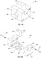
- FIG. 10 A is a perspective view of a press tool for forming a recess in the mounting member according to embodiments of the present invention.
- FIG. 10 B is an exploded perspective view of the press tool of FIG. 10 A .
- FIG. 11 A is a perspective view of a clamp member of the press tool of FIG. 10 A according to embodiments of the present invention.
- FIG. 11 B is a perspective view of a pin block member of the press tool of FIG. 10 A according to embodiments of the present invention.
- FIG. 11 C is a side view of a press form member of the press tool of FIG. 10 A according to embodiments of the present invention.
- FIG. 12 is a cross-sectional view of the press tool in combination with a mounting member according to embodiments of the present invention.
- first, second, etc. may be used herein to describe various elements, components, regions, layers and/or sections, these elements, components, regions, layers and/or sections should not be limited by these terms. These terms are only used to distinguish one element, component, region, layer or section from another region, layer, or section. Thus, a first element, component, region, layer, or section discussed below could be termed a second element, component, region, layer, or section without departing from the teachings of the present invention.
- the sequence of operations (or steps) is not limited to the order presented in the claims or figures unless specifically indicated otherwise.
- phrases such as “between X and Y” and “between about X and Y” should be interpreted to include X and Y.
- phrases such as “between about X and Y” mean “between about X and about Y.”
- phrases such as “from about X to Y” mean “from about X to about Y.”
- a telecommunications platform 200 according to embodiments of the present invention is illustrated.
- the telecommunications platform 200 is similar to the prior known telecommunications structure 10 illustrated in FIG. 1 and includes an antenna platform 230 having a plurality of mounting members (or pipes) 211 (i.e., a plurality of vertical members (or pipes) 112 and a plurality of horizontal members (or pipes) 114 ).
- the telecommunications platform 200 of the present invention differs from the prior known telecommunications structure 10 in that the telecommunications platform 200 utilizes a different mechanical connection 220 to secure the vertical and horizontal pipes 212 , 214 together. For example, as shown in FIG.
- At least one of the vertical or horizontal pipes 212 , 214 includes one or more cutout sections or recesses 216 configured to receive a corresponding horizontal or vertical pipe 214 , 212 and secured together via a fastener 217 (e.g., a threaded bolt).
- a fastener 217 e.g., a threaded bolt
- one or more of the mounting members 211 may be formed of steel.
- one or more of the mounting members 211 may be formed of a fiber-reinforced polymer.
- a fiber-reinforced polymer or “FRP” is a composite material made of a polymer matrix reinforced with fibers.
- the fiber-reinforced polymer that forms the one or more mounting pipes 211 of the present invention may comprise a polyester thermosetting plastic reinforced with a fiberglass.
- the fiber-reinforced polymer may comprise a “sandwich” composite or structure in which an open- or closed-cell-structured foam may be used as the core material (or middle layer) and fiber-reinforced polymers may be used to form the outer layers (i.e., the foam is sandwiched between the fiber-reinforced polymers).
- a variety of known materials may be used as the core material, for example, polystyrene foams, polyurethane, polyethylene, balsa wood, and aramid.
- Other examples of fiber-reinforced polymer mounting pipes are described in U.S. Utility patent application Ser. No. 17/473,079, filed Sep. 13, 2021, the disclosure of which is hereby incorporated herein in its entirety.
- each vertical pipe 212 of the telecommunications platform 200 may have a similar configuration.
- Each vertical pipe 212 has a length (L) and a diameter (D).
- each vertical pipe 212 includes one or more longitudinally spaced-apart recesses 216 .
- the recesses 216 may be formed by making a semi-cylindrical cut into the vertical pipe 212 .
- the recesses 216 may be formed by making a semi-cylindrical indention into the vertical pipe 212 using a press tool 400 described herein (see, e.g., FIG. 12 ).
- Each recess 216 is sized and configured to receive at least a portion of a corresponding mounting member 211 (e.g., horizontal pipe 214 ) (see, e.g., FIGS. 6 A- 6 B and FIG. 7 ). At least one aperture 212 a resides within each recess 216 . In some embodiments, aligned apertures 212 a reside within each recess 216 (i.e., on opposing sides of the vertical pipe 212 ), for example, when the recess 216 is formed by a press tool 400 , which is discussed in further detail below. Each aperture 212 a is configured to receive a fastener 217 when the vertical pipe 212 is secured to a respective horizontal pipe 214 (see, e.g., FIGS. 6 A- 6 B and FIG. 7 ).
- the recesses 216 may be formed to penetrate to different depths and/or have different shapes in the mounting pipe 211 (see, e.g., FIGS. 5 A- 5 E and FIGS. 8 A- 8 D ). As shown in FIG. 4 D , in some embodiments, the recesses 216 may penetrate to about the midpoint of the vertical pipe 212 (i.e., about half the diameter (D) of the vertical pipe 212 ).
- FIG. 4 E illustrates a support bracket 240 according to embodiments of the present invention.
- the support bracket 240 has an arcuate main body 242 that corresponds to the outer profile of the corresponding mounting member 211 (e.g., horizontal pipe 214 ) that will be received within a recess 216 .
- the support bracket 240 may be formed from the cutout section of the vertical pipe 212 that has been removed to form the recess 216 .
- An aperture 242 a resides in the center of the main body 242 of the support bracket 240 .
- the aperture 242 a is configured to receive the fastener 217 , for example, when the vertical pipe 212 is secured to a respective horizontal pipe 214 .
- the support bracket 240 may be used as part of the mechanical connection 120 to help further secure the vertical and horizontal pipes 212 , 214 together.
- the support bracket 240 may be positioned on the opposing side of vertical pipe 212 , opposite the recess 216 .
- a fastener 217 may then be inserted through respective apertures 242 a , 212 a , 214 a , in the support bracket 240 , vertical pipe 212 , and horizontal pipe 214 to secure them together.
- the support bracket 240 may provide additional structural support to the mechanical connection 220 , similar to a Belleville washer, and thus, the antenna frame 230 .
- each vertical pipe 212 ′ includes one or more spaced apart recesses 216 ′.
- Each recess 216 ′ is sized and configured to receive at least a portion of a corresponding horizontal pipe 214 (see, e.g., FIGS. 6 A- 6 B and FIG. 7 ).
- At least one aperture 212 a ′ resides within each recess 216 ′.
- Each aperture 212 a ′ is configured to receive a fastener 217 , for example, when the vertical pipe 212 ′ is secured to a respective horizontal pipe 214 (see, e.g., FIGS. 6 A- 6 B , and FIG. 7 ).
- the vertical pipe 212 ′ differs from the vertical pipe 212 described above in that the depth of the recesses 216 ′ formed in the vertical pipe 212 ′ does not penetrate as deep into the vertical pipe 212 ′ as compared to the depth of the recesses 216 of vertical pipe 212 . As shown in FIG. 5 B and FIG. 5 E , in some embodiments, the recesses 216 ′ penetrate to a depth that is less than the midpoint of the vertical pipe 212 ′ (i.e., less than half the diameter (D)). Similar to the vertical pipe 212 described herein, in some embodiments, each recess 216 ′ of vertical pipe 212 ′ may be formed by making a semi-cylindrical cut in the vertical pipe 212 ′. In other embodiments, discussed in further detail below, each recess 216 ′ may be formed by making a semi-cylindrical indentation with a press tool 300 (see, e.g., FIGS. 10 A- 12 ).
- FIGS. 6 A- 6 B and FIG. 7 illustrate the mechanical connections 220 , 220 ′ of the telecommunications structure 200 according to embodiments of the present invention utilizing the vertical pipes 212 , 212 ′ described herein.
- the horizontal pipes 214 , 214 ′ are received by receptive recesses 216 , 216 ′ in the corresponding vertical pipes 212 , 212 ′.
- a fastener 217 (e.g., a threaded bolt) is inserted through the apertures 212 a , 212 a ′ residing in the recesses 216 , 216 ′ of the vertical pipes 212 , 212 ′ and through a corresponding aperture 214 a , 214 a ′ in the horizontal pipes 214 , 214 ′ and secured with a nut 218 and washer 219 , thereby securing the vertical ( 212 , 212 ′) and horizontal ( 214 , 214 ′) pipes together.
- a fastener 217 e.g., a threaded bolt
- any of the mounting members 211 may include one or more spaced apart recesses 216 , 216 ′ that may be configured to receive at least a portion of a corresponding mounting member 211 (i.e., vertical pipes 212 , 212 ′ and/or horizontal pipes 214 , 214 ′).
- each of the horizontal pipes 214 , 214 ′ may include one or more longitudinally spaced-apart recesses 216 , 216 ′ configured to receive at least a portion of a corresponding vertical pipe 214 , 214 ′ (see, e.g., FIG. 3 ).
- FIGS. 8 A- 8 B illustrate exemplary shapes and depths of the recesses 216 in the mounting members 211 (i.e., vertical and/or horizontal pipes 212 , 214 ) according to embodiments of the present invention.
- FIG. 8 A illustrates the recess 216 penetrating the mounting member 211 at a depth that is even less than the embodiments shown in FIGS. 5 A- 5 E .
- FIG. 8 B illustrates recesses 216 having a hemi-hexagonal shape (e.g., have a generally flat bottom section 216 b ) (see also, e.g., FIG. 9 B ).
- the hemi-hexagonal shape of the recess 216 may be a cutout or flattened feature configured to interlock with an identical mating feature (i.e., recess 216 ) in a corresponding mounting member 211 )
- a telecommunications mount 300 according to embodiments of the present invention is illustrated.
- the properties and/or features of the telecommunications mount 300 and corresponding mounting members 311 i.e., vertical pipes 312 and horizontal pipes 314 ) may be as described above in reference to the telecommunications platform 200 shown in FIGS. 3 - 8 D and duplicate discussion thereof may be omitted herein for purposes of discussing FIGS. 9 A- 9 B .
- the telecommunications mount 300 is similar to the telecommunications platform 200 described herein and includes an antenna frame 330 having a plurality of mounting members 311 (i.e., a plurality of vertical pipes 312 and a plurality of horizontal pipes 314 ).
- Each vertical pipe 312 includes one or more longitudinally spaced-apart recesses 316 .
- Each recess 316 is sized and configured to receive at least a portion of a corresponding horizontal pipe 314 .
- At least one aperture 312 a resides within each recess 316 and is configured to receive a fastener 317 , for example, when the vertical pipe 312 is secured to a respective horizontal pipe 314 .
- the recesses 216 have a hemi-hexagonal shape with a generally flat bottom section 316 f (see also, e.g., FIG. 8 B and FIG. 8 C ).
- any of the mounting members 311 may include one or more spaced-apart recesses 316 that may be configured to receive at least a portion of a corresponding mounting member 311 (i.e., vertical pipes 312 and/or horizontal pipes 314 ).
- each of the horizontal pipes 314 may include one or more spaced apart recesses 316 configured to receive at least a portion of a corresponding vertical pipe 314 .
- the various embodiments illustrated above may provide multiple benefits to the mounts, platforms, and/or other structures discussed above.
- One potential advantage is the security of the joint itself.
- a U-bolt or similar fastener is employed to connect perpendicular round pipes, there may be a tendency for the pipes to be able to move slightly relative to each other. This tendency can increase over time, particularly of the U-bolt loosens somewhat. Not only can such movement cause potential mispositioning of elements (such as antennas) mounted on the pipes, but such movement between metallic elements can also contribute to Passive Intermodulation (PIM), which can negatively impact signal performance.
- PIM Passive Intermodulation
- PIM issues can also be addressed by forming one or both of the joined elements from a non-metallic material, such as the FRP discussed above, or by coating metallic materials with a non-metallic material (e.g., a polymer, a ceramic, or the like).
- a non-metallic material e.g., a polymer, a ceramic, or the like.
- the press tool 400 may be used to form the recesses 216 , 216 ′ in the mounting members 211 .
- the press tool 400 includes two clamp members 410 , a pin block 420 , and press form member 430 .
- the pin block 420 when secured together, the pin block 420 resides between the two clamp members 410 and at least a portion of the press form member 430 is configured to fit within a channel 404 formed by the secured together clamp members 410 .
- FIG. 11 A illustrates one of the clamp members 410 according to embodiments of the present invention.
- each clamp member 410 has a main body 411 with opposing sides 412 extending upwardly from the main body 411 to define a channel 404 therebetween.
- the channel 404 is sized and configured to receive at least a portion of the press form member 430 , for example, when the two clamp members 410 are secured together (see, e.g., FIG. 10 A and FIG. 12 ).
- the main body 411 of each clamp member 412 includes a recess 413 having an arcuate profile. When secured together, the recesses 413 of each clamp member 410 cooperate to form a tubular channel 402 that is sized and configured to hold a section of a mounting member 211 (see, e.g., FIG. 12 ).
- the main body 411 includes a second recess 415 residing along a bottom surface of the main body 411 and opposite to the channel 404 .
- the second recess 415 is sized and configured to receive a respective arm member 427 of the pin block 420 (see, e.g., FIG. 10 B ).
- the main body 411 of each clamp member 410 further includes a plurality of apertures 416 .
- the apertures 416 are sized and configured to receive a respective fastener 417 (e.g., a threaded bolt), for example, to secure the two clamp members 410 together.
- FIG. 11 B illustrates the pin block 420 of the press tool 400 according to embodiments of the present invention.
- the pin block 420 has a main body 422 having a plurality of apertures 426 .
- the apertures 426 are sized and configured to receive a respective fastener 417 .
- a pair of arms 427 extend radially outward from the main body 422 , each arm 427 extending outwardly in opposing directions.
- each arm 427 is configured to be received within the second recess 413 of a respective clamp member 410 (i.e., when the pin block 410 is secured between the clamp members 410 ) (see, e.g., FIGS. 10 A- 10 B ).
- the apertures 426 are positioned in the main body 422 of the pin block 420 to align with corresponding apertures 416 in each clamp member 410 such that a fastener 417 can be inserted through the aligned apertures 416 , 426 to secure the pin block 420 between the two clamp members 410 .
- the pin block 420 further includes a pin member 424 extending upwardly from the main body 422 .
- the pin member 424 is sized and configured to be received through an aperture 211 a ′ in the mounting member 211 (i.e., aperture 212 a in vertical pipe 212 or aperture 214 a in horizontal pipe 214 ) (see, e.g., FIG. 12 ).
- the pin member 424 is also sized and configured to be received within an aperture 434 in the press form member 430 (see, e.g., FIG. 10 B and FIG. 12 ).
- FIG. 11 C illustrates the press form member 430 of the press tool 400 according to embodiments of the present invention.
- the press form member 430 has a main body 432 with an aperture 434 extending therethrough. As discussed above, the aperture 434 is sized and configured to receive the pin member 424 of the pin block 420 .
- a bottom edge 431 of the press form member 430 has an arcuate shape that corresponds to the outer profile of a mounting member 211 and is configured to form the recess 216 in the mounting member 211 (i.e., vertical pipe 212 and/or horizontal pipe 214 ).
- FIG. 12 is a cross-sectional view illustrating a mounting member 211 secured within the press tool 400 .
- the pin member 424 is received by and extends through apertures 211 a in the mounting member 211 .
- the apertures 211 a indicate the location on the mounting member 211 where a recess 216 should be formed.
- the press form member 430 is guided downwardly within the channel 404 between the opposing sides 411 of the clamp members 410 and along the pin member 424 .
- press form member 430 moves downwardly, it compresses the mounting member 211 to form a recess 216 having a corresponding shape to the arcuate profile of the bottom edge 431 of the press form member 430 (in this instance, a generally semi-cylindrical shape).
- the press form member 430 compresses the mounting member 211 until the bottom edge 431 penetrates to the desired depth for the corresponding recess 216 being formed (see, e.g., FIGS. 4 D, 5 E and 8 A ).
- multiple press tools 400 may be secured along the length of the mounting member 211 to form multiple recesses 216 simultaneously.
Landscapes
- Mutual Connection Of Rods And Tubes (AREA)
Abstract
Description
Claims (20)
Priority Applications (1)
| Application Number | Priority Date | Filing Date | Title |
|---|---|---|---|
| US17/683,669 US12046795B2 (en) | 2021-03-24 | 2022-03-01 | Telecommunications mounting frames and methods of making same |
Applications Claiming Priority (2)
| Application Number | Priority Date | Filing Date | Title |
|---|---|---|---|
| US202163165357P | 2021-03-24 | 2021-03-24 | |
| US17/683,669 US12046795B2 (en) | 2021-03-24 | 2022-03-01 | Telecommunications mounting frames and methods of making same |
Publications (2)
| Publication Number | Publication Date |
|---|---|
| US20220311121A1 US20220311121A1 (en) | 2022-09-29 |
| US12046795B2 true US12046795B2 (en) | 2024-07-23 |
Family
ID=83363768
Family Applications (1)
| Application Number | Title | Priority Date | Filing Date |
|---|---|---|---|
| US17/683,669 Active 2042-03-10 US12046795B2 (en) | 2021-03-24 | 2022-03-01 | Telecommunications mounting frames and methods of making same |
Country Status (2)
| Country | Link |
|---|---|
| US (1) | US12046795B2 (en) |
| WO (1) | WO2022203821A1 (en) |
Families Citing this family (3)
| Publication number | Priority date | Publication date | Assignee | Title |
|---|---|---|---|---|
| US11483632B2 (en) * | 2019-09-27 | 2022-10-25 | Commscope Technologies Llc | Ballasted telecommunications equipment mounts and assemblies |
| US20230024333A1 (en) * | 2021-07-19 | 2023-01-26 | Commscope Technologies Llc | Monopole low-profile platform assemblies |
| AU2024216349A1 (en) * | 2024-08-26 | 2026-03-12 | Valmont Australia Pty Limited | Adjustable framework and components therefor |
Citations (32)
| Publication number | Priority date | Publication date | Assignee | Title |
|---|---|---|---|---|
| US2192904A (en) * | 1938-03-29 | 1940-03-12 | Starline | Method of making pipe connections |
| US2647267A (en) * | 1951-06-05 | 1953-08-04 | Ira J Mclaughlin | Knockdown bunk bed |
| US2812833A (en) * | 1953-10-26 | 1957-11-12 | William S O'nan | Collapsible mast construction |
| US3006669A (en) * | 1958-06-30 | 1961-10-31 | William H Novales | Shelving clamp |
| US3365722A (en) * | 1965-05-18 | 1968-01-23 | Blonder Tongue Elect | Pivoted antenna element locking mechanism |
| US3408655A (en) * | 1966-06-14 | 1968-10-29 | Dx Antenna | Multi-element high frequency antenna and element mounting means therefor |
| US3424178A (en) * | 1965-11-04 | 1969-01-28 | Yoshimi Yazaki | Small size constructions which are readily fabricated or dismantled |
| US3638814A (en) * | 1970-06-18 | 1972-02-01 | Mae H Lowery | Support stand |
| US4104642A (en) * | 1977-02-25 | 1978-08-01 | Rms Electronics, Inc. | T-shaped swivel joint for an antenna mounting structure |
| US4253224A (en) * | 1978-12-18 | 1981-03-03 | Brazeway, Inc. | Fixtureless method of making tube joints |
| US4493578A (en) * | 1982-09-30 | 1985-01-15 | Harsco Corporation | Scaffolding connector and system |
| US4603756A (en) * | 1984-02-29 | 1986-08-05 | Ulrich Layher | Metal pipe scaffolding |
| US4652890A (en) * | 1984-07-24 | 1987-03-24 | Crean Robert F | High rigidity, low center of gravity polar mount for dish type antenna |
| US4741081A (en) * | 1987-01-27 | 1988-05-03 | Tube Fab Of Afton Corporation | Method and apparatus for making t-tube fittings |
| US4867274A (en) * | 1987-01-24 | 1989-09-19 | Langer Ruth Geb Layher | Scaffold system |
| US5517744A (en) * | 1994-11-04 | 1996-05-21 | Cosco, Inc. | Press-fit tube-connection system |
| US5954305A (en) * | 1997-09-09 | 1999-09-21 | Summit Manufacturing, Inc. | Adaptable antenna mounting platform for fixed securement to an elongated mast pole |
| JP2000088173A (en) | 1998-07-16 | 2000-03-31 | Suiken Technology:Kk | Piping structure, existing pipe cutting construction method, flow non-cutting-off valve insertion construction method, sluice valve element and flow non- cutting-off insertion valve device |
| US6115004A (en) * | 1998-11-13 | 2000-09-05 | Mcginnis; Henry J. | Antenna support system |
| US6314595B1 (en) * | 2000-03-09 | 2001-11-13 | Joel Price | Interlocking bed frame with integrated ladder and safety rail systems |
| US6561473B1 (en) * | 2001-03-30 | 2003-05-13 | Pirod, Inc. | Universal pipe mounting clamp and assembly |
| WO2006057099A1 (en) | 2004-11-25 | 2006-06-01 | Nippon Steel Corporation | Joining metal tool for members, and structure and method for joining vertical frame members on upper and lower stories |
| US7578488B2 (en) * | 2005-02-01 | 2009-08-25 | The Southern Company | Temporary arm gain and saddle |
| US20110279347A1 (en) * | 2010-05-17 | 2011-11-17 | Kenwood Telecom Corporation | Platform assemblies for radio transmission towers |
| US8439166B2 (en) * | 2008-01-24 | 2013-05-14 | Wilhelm Layher Verwaltungs-Gmbh | Vertical frame intended for the construction of a frame support, a supporting scaffold and/or a supporting scaffold tower |
| US20130283724A1 (en) | 2012-04-30 | 2013-10-31 | James Scot LINDQUIST | Utility dowel bracket |
| US9972906B2 (en) * | 2015-01-15 | 2018-05-15 | Outthink Technologies, Llc | Two-way antenna mounting bracket and assembly with independently adjustable electromechanical antenna tilt and azimuthal steering for beam reshaping |
| US20180238474A1 (en) | 2017-02-21 | 2018-08-23 | Henry Alexander Braddock, III | Square Tube Forming Process |
| US10495237B1 (en) * | 2017-03-29 | 2019-12-03 | Robroy Industries—Texas, LLC | Piping and conduit support rack |
| US10863829B2 (en) * | 2015-08-24 | 2020-12-15 | L&P Property Management Company | Pultruded adjustable bed frame |
| US10974348B2 (en) * | 2016-06-02 | 2021-04-13 | Priefert Mfg. Co, Inc. | Method for forming a brazed joint |
| US20210156148A1 (en) * | 2017-08-22 | 2021-05-27 | Rtl Materials Ltd. | Slit locking clamp for mast and support assembly |
-
2022
- 2022-03-01 WO PCT/US2022/018237 patent/WO2022203821A1/en not_active Ceased
- 2022-03-01 US US17/683,669 patent/US12046795B2/en active Active
Patent Citations (33)
| Publication number | Priority date | Publication date | Assignee | Title |
|---|---|---|---|---|
| US2192904A (en) * | 1938-03-29 | 1940-03-12 | Starline | Method of making pipe connections |
| US2647267A (en) * | 1951-06-05 | 1953-08-04 | Ira J Mclaughlin | Knockdown bunk bed |
| US2812833A (en) * | 1953-10-26 | 1957-11-12 | William S O'nan | Collapsible mast construction |
| US3006669A (en) * | 1958-06-30 | 1961-10-31 | William H Novales | Shelving clamp |
| US3365722A (en) * | 1965-05-18 | 1968-01-23 | Blonder Tongue Elect | Pivoted antenna element locking mechanism |
| US3424178A (en) * | 1965-11-04 | 1969-01-28 | Yoshimi Yazaki | Small size constructions which are readily fabricated or dismantled |
| US3408655A (en) * | 1966-06-14 | 1968-10-29 | Dx Antenna | Multi-element high frequency antenna and element mounting means therefor |
| US3638814A (en) * | 1970-06-18 | 1972-02-01 | Mae H Lowery | Support stand |
| US4104642A (en) * | 1977-02-25 | 1978-08-01 | Rms Electronics, Inc. | T-shaped swivel joint for an antenna mounting structure |
| US4253224A (en) * | 1978-12-18 | 1981-03-03 | Brazeway, Inc. | Fixtureless method of making tube joints |
| US4493578A (en) * | 1982-09-30 | 1985-01-15 | Harsco Corporation | Scaffolding connector and system |
| US4603756A (en) * | 1984-02-29 | 1986-08-05 | Ulrich Layher | Metal pipe scaffolding |
| US4652890A (en) * | 1984-07-24 | 1987-03-24 | Crean Robert F | High rigidity, low center of gravity polar mount for dish type antenna |
| US4867274A (en) * | 1987-01-24 | 1989-09-19 | Langer Ruth Geb Layher | Scaffold system |
| US4741081A (en) * | 1987-01-27 | 1988-05-03 | Tube Fab Of Afton Corporation | Method and apparatus for making t-tube fittings |
| US5517744A (en) * | 1994-11-04 | 1996-05-21 | Cosco, Inc. | Press-fit tube-connection system |
| US5954305A (en) * | 1997-09-09 | 1999-09-21 | Summit Manufacturing, Inc. | Adaptable antenna mounting platform for fixed securement to an elongated mast pole |
| JP2000088173A (en) | 1998-07-16 | 2000-03-31 | Suiken Technology:Kk | Piping structure, existing pipe cutting construction method, flow non-cutting-off valve insertion construction method, sluice valve element and flow non- cutting-off insertion valve device |
| US6115004A (en) * | 1998-11-13 | 2000-09-05 | Mcginnis; Henry J. | Antenna support system |
| US6314595B1 (en) * | 2000-03-09 | 2001-11-13 | Joel Price | Interlocking bed frame with integrated ladder and safety rail systems |
| US6561473B1 (en) * | 2001-03-30 | 2003-05-13 | Pirod, Inc. | Universal pipe mounting clamp and assembly |
| WO2006057099A1 (en) | 2004-11-25 | 2006-06-01 | Nippon Steel Corporation | Joining metal tool for members, and structure and method for joining vertical frame members on upper and lower stories |
| US7578488B2 (en) * | 2005-02-01 | 2009-08-25 | The Southern Company | Temporary arm gain and saddle |
| US8439166B2 (en) * | 2008-01-24 | 2013-05-14 | Wilhelm Layher Verwaltungs-Gmbh | Vertical frame intended for the construction of a frame support, a supporting scaffold and/or a supporting scaffold tower |
| US9385413B2 (en) * | 2010-05-17 | 2016-07-05 | Kenwood Telecom Corporation | Platform assemblies for radio transmission towers |
| US20110279347A1 (en) * | 2010-05-17 | 2011-11-17 | Kenwood Telecom Corporation | Platform assemblies for radio transmission towers |
| US20130283724A1 (en) | 2012-04-30 | 2013-10-31 | James Scot LINDQUIST | Utility dowel bracket |
| US9972906B2 (en) * | 2015-01-15 | 2018-05-15 | Outthink Technologies, Llc | Two-way antenna mounting bracket and assembly with independently adjustable electromechanical antenna tilt and azimuthal steering for beam reshaping |
| US10863829B2 (en) * | 2015-08-24 | 2020-12-15 | L&P Property Management Company | Pultruded adjustable bed frame |
| US10974348B2 (en) * | 2016-06-02 | 2021-04-13 | Priefert Mfg. Co, Inc. | Method for forming a brazed joint |
| US20180238474A1 (en) | 2017-02-21 | 2018-08-23 | Henry Alexander Braddock, III | Square Tube Forming Process |
| US10495237B1 (en) * | 2017-03-29 | 2019-12-03 | Robroy Industries—Texas, LLC | Piping and conduit support rack |
| US20210156148A1 (en) * | 2017-08-22 | 2021-05-27 | Rtl Materials Ltd. | Slit locking clamp for mast and support assembly |
Non-Patent Citations (2)
| Title |
|---|
| PCT Notification of Transmittal of the International Search Report and the Written Opinion of the International Searching Authority, or the Declaration, mailed Jun. 13, 2022, in corresponding International Application No. PCT/US2022/018237. |
| Utility U.S. Appl. No. 17/473,079, filed Sep. 13, 2021 (including Official Filing Receipt). |
Also Published As
| Publication number | Publication date |
|---|---|
| US20220311121A1 (en) | 2022-09-29 |
| WO2022203821A1 (en) | 2022-09-29 |
Similar Documents
| Publication | Publication Date | Title |
|---|---|---|
| US12046795B2 (en) | Telecommunications mounting frames and methods of making same | |
| US20220085481A1 (en) | Assemblies for reducing passive intermodulation in telecommunications structures | |
| CA2908558C (en) | Lightweight support structure, method of producing a lightweight support structure, composite sandwich panel and method of producing a composite sandwich panel | |
| US11316267B2 (en) | Devices and methods for mitigating external passive intermodulation sources in base station antennas | |
| US20230318162A1 (en) | Universal small cell antenna mounts and antenna mount assemblies | |
| CA2649585C (en) | Cast structural connectors | |
| US20180209575A1 (en) | Non-metallic clip connection system | |
| CA2649585E (en) | Cast structural connectors | |
| CN112470357A (en) | cable hanger assembly | |
| EP3359824B1 (en) | Three-sided corner assembly | |
| US4673606A (en) | Load-introducing armature as component part of a laminated structural element | |
| CN211059270U (en) | Nonlinear metamaterial vibration isolator with quasi-zero rigidity | |
| US20220205233A1 (en) | Iso-truss structure and coupling mechanism for iso-truss structure | |
| CN107323022B (en) | Adhesive joint structure of composite material and metal material and preparation method thereof | |
| AU2022335261B2 (en) | Low-pim dual pipe clamp for cellular base station antenna sites | |
| EP4279754A1 (en) | Joints of composite frames for optics support structure | |
| CN202651360U (en) | High precision antenna reflection plane, and satellite receiving antenna with same | |
| CN211315751U (en) | Grid | |
| CA2422296C (en) | 3-dimensional wave-guiding structure for horn or tube-type waveguides | |
| CN215977653U (en) | Node structure for building and building structure | |
| CN217601694U (en) | Assembled steel-wood structure node with built-in lock | |
| CN220225764U (en) | Foam insulation board capable of being spliced | |
| US20250237033A1 (en) | Multi-Piece Underground Base for a Static Structure | |
| KR102066441B1 (en) | Connector of Geodesic Sphere | |
| US20090013627A1 (en) | Insulated Supports |
Legal Events
| Date | Code | Title | Description |
|---|---|---|---|
| FEPP | Fee payment procedure |
Free format text: ENTITY STATUS SET TO UNDISCOUNTED (ORIGINAL EVENT CODE: BIG.); ENTITY STATUS OF PATENT OWNER: LARGE ENTITY |
|
| AS | Assignment |
Owner name: COMMSCOPE TECHNOLOGIES LLC, NORTH CAROLINA Free format text: ASSIGNMENT OF ASSIGNORS INTEREST;ASSIGNORS:CROSS, BRIAN DOUGLAS;HANSON, ROGER K.;MANN, CHARLES J.;SIGNING DATES FROM 20220207 TO 20220211;REEL/FRAME:059141/0540 |
|
| STPP | Information on status: patent application and granting procedure in general |
Free format text: DOCKETED NEW CASE - READY FOR EXAMINATION |
|
| AS | Assignment |
Owner name: COMMSCOPE TECHNOLOGIES LLC, NORTH CAROLINA Free format text: CONFIRMATORY ASSIGNMENT;ASSIGNOR:FULLER, DOUGLAS R.;REEL/FRAME:060254/0450 Effective date: 20210923 |
|
| STPP | Information on status: patent application and granting procedure in general |
Free format text: NON FINAL ACTION MAILED |
|
| STPP | Information on status: patent application and granting procedure in general |
Free format text: RESPONSE TO NON-FINAL OFFICE ACTION ENTERED AND FORWARDED TO EXAMINER |
|
| STPP | Information on status: patent application and granting procedure in general |
Free format text: NOTICE OF ALLOWANCE MAILED -- APPLICATION RECEIVED IN OFFICE OF PUBLICATIONS |
|
| AS | Assignment |
Owner name: JPMORGAN CHASE BANK, N.A., AS COLLATERAL AGENT, NEW YORK Free format text: PATENT SECURITY AGREEMENT (ABL);ASSIGNORS:ARRIS ENTERPRISES LLC;COMMSCOPE TECHNOLOGIES LLC;COMMSCOPE, INC. OF NORTH CAROLINA;REEL/FRAME:067252/0657 Effective date: 20240425 Owner name: JPMORGAN CHASE BANK, N.A., AS COLLATERAL AGENT, NEW YORK Free format text: PATENT SECURITY AGREEMENT (TERM);ASSIGNORS:ARRIS ENTERPRISES LLC;COMMSCOPE TECHNOLOGIES LLC;COMMSCOPE, INC. OF NORTH CAROLINA;REEL/FRAME:067259/0697 Effective date: 20240425 |
|
| STPP | Information on status: patent application and granting procedure in general |
Free format text: PUBLICATIONS -- ISSUE FEE PAYMENT RECEIVED |
|
| STPP | Information on status: patent application and granting procedure in general |
Free format text: PUBLICATIONS -- ISSUE FEE PAYMENT VERIFIED |
|
| AS | Assignment |
Owner name: OUTDOOR WIRELESS NETWORKS LLC, NORTH CAROLINA Free format text: ASSIGNMENT OF ASSIGNORS INTEREST;ASSIGNOR:COMMSCOPE TECHNOLOGIES LLC;REEL/FRAME:068107/0089 Effective date: 20240701 |
|
| STCF | Information on status: patent grant |
Free format text: PATENTED CASE |
|
| AS | Assignment |
Owner name: JPMORGAN CHASE BANK, N.A., AS COLLATERAL AGENT, NEW YORK Free format text: PATENT SECURITY AGREEMENT (TERM);ASSIGNOR:OUTDOOR WIRELESS NETWORKS LLC;REEL/FRAME:068770/0632 Effective date: 20240813 Owner name: JPMORGAN CHASE BANK, N.A., AS COLLATERAL AGENT, NEW YORK Free format text: PATENT SECURITY AGREEMENT (ABL);ASSIGNOR:OUTDOOR WIRELESS NETWORKS LLC;REEL/FRAME:068770/0460 Effective date: 20240813 |
|
| CC | Certificate of correction | ||
| AS | Assignment |
Owner name: APOLLO ADMINISTRATIVE AGENCY LLC, NEW YORK Free format text: SECURITY INTEREST;ASSIGNORS:ARRIS ENTERPRISES LLC;COMMSCOPE TECHNOLOGIES LLC;COMMSCOPE INC., OF NORTH CAROLINA;AND OTHERS;REEL/FRAME:069889/0114 Effective date: 20241217 |
|
| AS | Assignment |
Owner name: COMMSCOPE TECHNOLOGIES LLC, NORTH CAROLINA Free format text: RELEASE OF SECURITY INTEREST AT REEL/FRAME 067259/0697;ASSIGNOR:JPMORGAN CHASE BANK, N.A., AS COLLATERAL AGENT;REEL/FRAME:069790/0575 Effective date: 20241217 Owner name: COMMSCOPE, INC. OF NORTH CAROLINA, NORTH CAROLINA Free format text: RELEASE OF SECURITY INTEREST AT REEL/FRAME 067259/0697;ASSIGNOR:JPMORGAN CHASE BANK, N.A., AS COLLATERAL AGENT;REEL/FRAME:069790/0575 Effective date: 20241217 Owner name: ARRIS ENTERPRISES LLC (F/K/A ARRIS ENTERPRISES, INC.), NORTH CAROLINA Free format text: RELEASE OF SECURITY INTEREST AT REEL/FRAME 067259/0697;ASSIGNOR:JPMORGAN CHASE BANK, N.A., AS COLLATERAL AGENT;REEL/FRAME:069790/0575 Effective date: 20241217 Owner name: OUTDOOR WIRELESS NETWORKS LLC, NORTH CAROLINA Free format text: RELEASE OF SECURITY INTEREST AT REEL/FRAME 068770/0632;ASSIGNOR:JPMORGAN CHASE BANK, N.A., AS COLLATERAL AGENT;REEL/FRAME:069743/0264 Effective date: 20241217 |
|
| AS | Assignment |
Owner name: OUTDOOR WIRELESS NETWORKS LLC, NORTH CAROLINA Free format text: PARTIAL TERMINATION AND RELEASE OF SECURITY INTEREST IN PATENTS RECORDED AT REEL 069889/FRAME 0114;ASSIGNOR:APOLLO ADMINISTRATIVE AGENCY LLC;REEL/FRAME:070154/0341 Effective date: 20250131 Owner name: OUTDOOR WIRELESS NETWORKS LLC, NORTH CAROLINA Free format text: PARTIAL TERMINATION AND RELEASE OF SECURITY INTEREST IN PATENTS;ASSIGNOR:U.S. BANK TRUST COMPANY, NATIONAL ASSOCIATION;REEL/FRAME:070154/0183 Effective date: 20250131 Owner name: OUTDOOR WIRELESS NETWORKS LLC, NORTH CAROLINA Free format text: RELEASE (REEL 068770 / FRAME 0460);ASSIGNOR:JPMORGAN CHASE BANK, N.A.;REEL/FRAME:070149/0432 Effective date: 20250131 |