US12044763B2 - Magnetic resonance imaging apparatus, image analyzer, and fluid analysis method - Google Patents
Magnetic resonance imaging apparatus, image analyzer, and fluid analysis method Download PDFInfo
- Publication number
- US12044763B2 US12044763B2 US18/073,178 US202218073178A US12044763B2 US 12044763 B2 US12044763 B2 US 12044763B2 US 202218073178 A US202218073178 A US 202218073178A US 12044763 B2 US12044763 B2 US 12044763B2
- Authority
- US
- United States
- Prior art keywords
- fluid
- flow velocity
- fluid parameter
- magnetic resonance
- imaging apparatus
- Prior art date
- Legal status (The legal status is an assumption and is not a legal conclusion. Google has not performed a legal analysis and makes no representation as to the accuracy of the status listed.)
- Active, expires
Links
Images


Classifications
-
- G—PHYSICS
- G06—COMPUTING OR CALCULATING; COUNTING
- G06T—IMAGE DATA PROCESSING OR GENERATION, IN GENERAL
- G06T7/00—Image analysis
- G06T7/0002—Inspection of images, e.g. flaw detection
- G06T7/0012—Biomedical image inspection
-
- G—PHYSICS
- G01—MEASURING; TESTING
- G01R—MEASURING ELECTRIC VARIABLES; MEASURING MAGNETIC VARIABLES
- G01R33/00—Arrangements or instruments for measuring magnetic variables
- G01R33/20—Arrangements or instruments for measuring magnetic variables involving magnetic resonance
- G01R33/44—Arrangements or instruments for measuring magnetic variables involving magnetic resonance using nuclear magnetic resonance [NMR]
- G01R33/48—NMR imaging systems
- G01R33/54—Signal processing systems, e.g. using pulse sequences ; Generation or control of pulse sequences; Operator console
- G01R33/56—Image enhancement or correction, e.g. subtraction or averaging techniques, e.g. improvement of signal-to-noise ratio and resolution
- G01R33/563—Image enhancement or correction, e.g. subtraction or averaging techniques, e.g. improvement of signal-to-noise ratio and resolution of moving material, e.g. flow contrast angiography
- G01R33/56341—Diffusion imaging
-
- A—HUMAN NECESSITIES
- A61—MEDICAL OR VETERINARY SCIENCE; HYGIENE
- A61B—DIAGNOSIS; SURGERY; IDENTIFICATION
- A61B5/00—Measuring for diagnostic purposes; Identification of persons
- A61B5/0033—Features or image-related aspects of imaging apparatus, e.g. for MRI, optical tomography or impedance tomography apparatus; Arrangements of imaging apparatus in a room
-
- G—PHYSICS
- G01—MEASURING; TESTING
- G01R—MEASURING ELECTRIC VARIABLES; MEASURING MAGNETIC VARIABLES
- G01R33/00—Arrangements or instruments for measuring magnetic variables
- G01R33/20—Arrangements or instruments for measuring magnetic variables involving magnetic resonance
- G01R33/44—Arrangements or instruments for measuring magnetic variables involving magnetic resonance using nuclear magnetic resonance [NMR]
- G01R33/48—NMR imaging systems
- G01R33/54—Signal processing systems, e.g. using pulse sequences ; Generation or control of pulse sequences; Operator console
- G01R33/56—Image enhancement or correction, e.g. subtraction or averaging techniques, e.g. improvement of signal-to-noise ratio and resolution
- G01R33/563—Image enhancement or correction, e.g. subtraction or averaging techniques, e.g. improvement of signal-to-noise ratio and resolution of moving material, e.g. flow contrast angiography
- G01R33/56308—Characterization of motion or flow; Dynamic imaging
- G01R33/56316—Characterization of motion or flow; Dynamic imaging involving phase contrast techniques
-
- A—HUMAN NECESSITIES
- A61—MEDICAL OR VETERINARY SCIENCE; HYGIENE
- A61B—DIAGNOSIS; SURGERY; IDENTIFICATION
- A61B5/00—Measuring for diagnostic purposes; Identification of persons
- A61B5/05—Detecting, measuring or recording for diagnosis by means of electric currents or magnetic fields; Measuring using microwaves or radio waves
- A61B5/055—Detecting, measuring or recording for diagnosis by means of electric currents or magnetic fields; Measuring using microwaves or radio waves involving electronic [EMR] or nuclear [NMR] magnetic resonance, e.g. magnetic resonance imaging
-
- G—PHYSICS
- G06—COMPUTING OR CALCULATING; COUNTING
- G06T—IMAGE DATA PROCESSING OR GENERATION, IN GENERAL
- G06T2207/00—Indexing scheme for image analysis or image enhancement
- G06T2207/10—Image acquisition modality
- G06T2207/10072—Tomographic images
- G06T2207/10088—Magnetic resonance imaging [MRI]
-
- G—PHYSICS
- G06—COMPUTING OR CALCULATING; COUNTING
- G06T—IMAGE DATA PROCESSING OR GENERATION, IN GENERAL
- G06T2207/00—Indexing scheme for image analysis or image enhancement
- G06T2207/30—Subject of image; Context of image processing
- G06T2207/30004—Biomedical image processing
- G06T2207/30016—Brain
-
- G—PHYSICS
- G06—COMPUTING OR CALCULATING; COUNTING
- G06T—IMAGE DATA PROCESSING OR GENERATION, IN GENERAL
- G06T2207/00—Indexing scheme for image analysis or image enhancement
- G06T2207/30—Subject of image; Context of image processing
- G06T2207/30004—Biomedical image processing
- G06T2207/30101—Blood vessel; Artery; Vein; Vascular
- G06T2207/30104—Vascular flow; Blood flow; Perfusion
Definitions
- the present invention relates to a magnetic resonance imaging (hereinafter, abbreviated as MRI) apparatus and an analysis technique of measurement data obtained by the MRI apparatus, and in particular, to an analysis technique of a diffusion tensor image.
- MRI magnetic resonance imaging
- Analyzing a flow of fluid that circulates human brain and body allows obtainment of effective indicators for diagnosis of various diseases.
- fluid parameters such as wall shear stress (WSS), fluid kinetic energy (KE), and kinetic energy loss (EL), are effective indicators for detecting an abnormal flow of blood or cerebrospinal fluid, and there are proposed various techniques for measuring and analyzing those indicators.
- Patent Document 1 discloses a method that uses the phase contrast (PC) method of MRI to analyze kinetic energy loss and others, from obtained measurement data.
- PC phase contrast
- a gradient pulse for dephasing NMR signals is combined with a gradient pulse for rephasing, thereby differentiating the phase between a signal from a stationary portion and a signal from a portion with a flow, and a velocity of fluid such as blood flow in a desired region is calculated.
- difference information of adjacent vectors is calculated from a map of velocity vector values of the fluid obtained by the PC method (a blood flow vector image having the velocity vector value as a pixel value), and then using this difference information, EL and others are calculated.
- Imaging methods of MRI that allows fluid observation include diffusion weighted imaging (DWI) and diffusion tensor imaging (DTI). It is reported in Magnetic Resonance in Medicine 2021; 86, pp. 1369 to 1382 (hereinafter, referred to as Non-Patent Document) that DTI is a method to show information representing anisotropy of diffusion for each voxel by a diffusion tensor, from measurement data obtained by performing DWI using MPG pulses in at least six directions, and this method is effective for observation of a flow such as pseudo-random flow of cerebrospinal fluid.
- DWI diffusion weighted imaging
- DTI diffusion tensor imaging
- the PC method it is required to execute repeatedly a pulse sequence for applying a rephasing gradient pulse to a dephasing gradient pulse that diffuses the phase, after a predetermined time interval, so as to acquire a signal.
- spatial resolution of an image is relatively low. Taking the difference between neighboring vectors in a blood flow vector image having the low spatial resolution may result in that a differential value of the flow velocity is calculated lower than an actual differential value. Therefore, there is a possibility that errors in blood flow parameter values such as EL become larger, because these fluid parameter values are obtained based on thus calculated differential value of the flow velocity. In particular, when the fluid velocity is low, such errors are likely to expand.
- An object of the present invention is to provide a technique to accurately calculate the fluid parameters, using MRI.
- the present invention also aims at improving accuracy in the fluid parameter calculation, especially for the fluid at low velocity.
- the present invention uses flow velocity information obtained by diffusion tensor imaging and a model of a flow velocity distribution, to calculate a differential vector of the flow velocity, and then, the fluid parameters are obtained.
- an MRI apparatus of the present invention comprises a measurement unit configured to execute a pulse sequence of diffusion-weighted imaging including an MPG pulse to acquire measurement data, and a calculation unit configured to calculate a pseudo diffusion tensor having information on a flow velocity and diffusion of fluid within an examination target, using the measurement data acquired by the measurement unit, wherein the calculation unit includes a fluid parameter calculator configured to calculate a fluid parameter other than the pseudo diffusion tensor, using the pseudo diffusion tensor and an estimation model of an intra-voxel distribution of the flow velocity.
- An image analyzer of the present invention is an independent analyzer having a function of the calculation unit of the MRI apparatus as described above, comprising a receiving unit configured to receive the measurement data measured in an MRI apparatus or a value of the pseudo diffusion tensor calculated from the measurement data, a calculation unit configured to calculate a fluid parameter using the measurement data or the value of the pseudo diffusion tensor received by the receiving unit, wherein the calculation unit includes a fluid parameter calculator configured to calculate the fluid parameter serving as an indicator that represents a characteristic of a flow of fluid, using the pseudo diffusion tensor, and an estimation model of a flow velocity distribution.
- the present invention provides a fluid analysis method using a diffusion tensor image of an examination target containing fluid, obtained by an MRI apparatus, comprising the following steps, calculating dispersion of a flow velocity of the fluid using the diffusion tensor image; calculating a differential vector of the flow velocity using the dispersion and a distribution shape of intra-voxel flow velocity; and calculating a fluid parameter representing a characteristic of a flow of the fluid, using the differential vector.
- the present invention provides a novel method of calculating the fluid parameters from DTI (diffusion tensor imaging), using an estimated distribution of the fluid in a voxel.
- the present invention utilizes the flow velocity distribution in the voxel and avoids calculation errors associated with low resolution, unlike the PC method using the averaged flow velocity in the voxel and a difference in the flow velocity between the voxels. Accordingly, it is possible to accurately calculate the fluid parameter. Particularly for the fluid at low velocity, lowering of calculation accuracy due to reduction in spatial resolution can be prevented.
- FIG. 1 illustrates an overview of an MRI apparatus
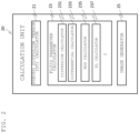
- FIG. 2 is a functional block diagram of a calculation unit
- FIG. 3 is a flowchart illustrating a process of a fluid parameter calculator
- FIG. 4 illustrates an example of a pulse sequence used for diffusion tensor imaging
- FIG. 5 illustrates relationships between various flows, and diffusion tensors (DT) respectively associated therewith;
- FIG. 6 illustrates an example of a brain image and its diffusion tensor image
- FIG. 7 schematically illustrates a relationship between a linear flow and a diffusion gradient
- FIGS. 8 A and 8 B illustrate examples of an estimation model of a flow velocity distribution
- FIG. 9 schematically illustrates a flow, mixing the linear flow and the diffusion gradient
- FIG. 10 is a functional block diagram showing an example of the calculation unit according to a second embodiment
- FIG. 11 is a functional block diagram of the calculation unit according to a third embodiment.
- FIGS. 12 A and 12 B each illustrates an example of GUI according to the third embodiment.
- the configuration of the MRI apparatus 1 is similar to a configuration of general MRI apparatuses, including a magnet 11 configured to generate a uniform static magnetic field in examination space where a subject is placed, a gradient magnetic field coil 13 configured to provide a magnetic field gradient with respect to the static magnetic field generated by the magnet 11 , a probe 12 having a transmission coil and a receiving coil, the transmission coil applying a pulse-like RF magnetic field to the subject and causing nuclear magnetic resonance to nucleus of atoms constituting tissue of the subject, and the receiving coil receiving a nuclear magnetic resonance signal generated from the subject, a receiver 14 connected to the receiving coil, an RF magnetic field generator 15 connected with the transmission coil, a gradient magnetic field power source 16 connected with the gradient magnetic field coil 13 , a sequencer 17 configured to control the receiver 14 , the RF magnetic field generator 15 , and the gradient magnetic field power source 16 according to a predetermined pulse sequence, and a
- the nuclear magnetic resonance signals received by the receiver 14 of the measurement unit 10 are digitized and passed to the computer 200 as measurement data.
- the computer 200 functions as a calculation unit 20 for performing various operations including image generation on the measurement data of the measurement unit 10 , and as a control system to control the entire MRI apparatus.
- the computer 200 can be configured by a general-purpose computer or a workstation provided with a CPU and a memory.
- the computer 200 may be a computer or a workstation independent of the MRI apparatus, capable of exchanging data with the MRI apparatus.
- all or a part of the functions of the calculation unit 20 can be performed by an independent device (image analyzer).
- This type of image analyzer has a receiving unit for receiving data from the MRI apparatus, and implements an image analysis function similar to that of the computer 200 , which will be described below.
- the MRI apparatus features that the measurement unit 10 performs measurement using a pulse sequence of diffusion-weighted imaging (DWI), and the calculation unit 20 uses the measurement data obtained by the DWI to calculate a fluid parameter for detecting an abnormality in a flow of fluid such as blood or cerebrospinal fluid passing through the body of the subject. Therefore, the computer 200 sends a command to the sequencer 17 (measurement controller) and controls the measurement unit 10 to execute the DWI sequence under an imaging condition specified by a user via an input device (input unit) 30 or a similar unit. Then, using the measured data, the calculation unit 20 performs computations to calculate the fluid parameter as described above. If necessary, a parameter image having values of the calculated parameter as pixel values may be generated and displayed on a display device 40 , and stored in a storage medium 50 or transferred to another storage device such as a medical information database.
- DWI pulse sequence of diffusion-weighted imaging
- FIG. 2 is one example of a functional block diagram of the calculation unit 20 that implements the above functions.
- the calculation unit 20 comprises a DT calculator 21 configured to process the measurement data of DWI to calculate data including a pseudo diffusion tensor (tensor representing mixed information of a flow velocity and diffusion), a fluid parameter calculator 23 configured to calculate a fluid parameter using a fluid vector, and an image generator 25 .
- a pseudo diffusion tensor tensor representing mixed information of a flow velocity and diffusion
- a fluid parameter calculator 23 configured to calculate a fluid parameter using a fluid vector
- an image generator 25 an image generator
- the fluid parameter calculator 23 includes a dispersion calculator 231 configured to calculate dispersion of the flow velocity for each pixel (voxel of the DT image), a differential calculator 233 configured to calculate a differential vector of the flow velocity, using the dispersion calculated by the dispersion calculator 231 and an estimation model of the calculated dispersion and a distribution of the flow velocity (the shape of the distribution in the voxel), and various-parameter calculators configured to calculate individual fluid parameters using the differential vector.
- the fluid parameters include, in addition to WSS and EL, PG (pressure gradient) and OSI (oscillatory shear index), for instance.
- FIG. 2 illustrates only a WSS calculator 235 and an EL calculator 237 for calculating WSS and EL, respectively, as representative examples.
- Functions of the DT calculator 21 for calculating a pseudo diffusion tensor from the measurement data of DWI are similar to those of conventional DTI, and these functions are well known.
- the MRI apparatus of the present embodiment features that the fluid parameter calculator 23 utilizes the pseudo diffusion tensor obtained by DTI to calculate a highly accurate fluid parameter that cannot be obtained by the PC (phase contrast) method.
- the fluid parameter calculation will be described specifically in the embodiments described later. In the following, a process common to each embodiment will be described schematically with reference to FIG. 3 .
- the measurement unit 10 executes a pulse sequence of DWI (diffusion-weighted imaging) and collects measurement data (S 1 ).
- An EPI (echo planar imaging) sequence is generally used as the pulse sequence of DWI, but other pulse sequences such as multi-shot EPI and SS (single shot) FSE may also be employed.
- FIG. 4 illustrates a typical pulse sequence of DWI.
- the reference numerals 401 and 403 indicate RF pulses
- 402 and 404 indicate slice gradient (Gs)
- the reference numeral 405 indicates phase-encoded gradient (Gp)
- 406 indicates readout gradient (Gr)
- 407 indicates NMR signals.
- the pulse sequence of DWI features that gradient magnetic field pulses (MPG pulses) 408 and 409 that promote phase diffusion of fluid, are applied before and after applying the 180-degree RF pulse 403 that reverses magnetization excited by the exciting RF pulse 401 .
- MPG pulses gradient magnetic field pulses
- Differentiating the intensity between the MPG pulses 408 and 409 causes phase dispersion corresponding to a difference in velocity of the fluid in the voxel (velocity dispersion), resulting in reduction of signal intensity of the voxel.
- this reduction in signal intensity can provide information on the velocity dispersion (pseudo diffusion) of the fluid in the voxel. That is, in the case where fluid is targeted, it is possible to obtain information of flow velocity dispersion by DWI.
- An indicator of the intensity of the MPG pulse is called b-value.
- b-value When obtaining fluid parameters for the fluid at high velocity, a relatively low b-value is preferable.
- the b-value may be set in advance as multiple b-values within a predetermined range, or the user can set a specific b-value.
- FIG. 4 illustrates an example where the MPG pulses are applied in the readout direction (Gr-axis).
- the diffusion tensor imaging (DTI) requires, however, application of MPG signals in six or more directions in order to calculate DT.
- the measurement is performed in the same manner as in FIG. 4 for a plurality of axes set in advance.
- phase-encoded gradient pulses 405 and reversed readout gradient pulses 406 are applied, after one excitation RF pulse, thereby obtaining a plurality of NMR signals 407 constituting one image.
- the NMR signals 407 are arranged at positions in the k-space determined by the applied phase encoding amount and the readout gradient magnetic field, passed to the computer 200 as digital data (measurement data), and in the computer 200 , the calculation unit 20 performs various operations.
- the calculation unit 20 calculates a diffusion tensor for each voxel (each pixel) first in the DT calculator 21 (S 2 ).
- the diffusion tensor DT can be determined by obtaining the slope of the corresponding straight line expressed by the following Equation 1, from the signal intensity of multiple DWI taken by varying b-vector, and the diffusion tensor DT is expressed by a matrix of 3 ⁇ 3.
- Eigenvalues and eigenvectors can be obtained by diagonalizing this diffusion tensor DT. This conversion into the eigenvalues and eigenvectors allows obtainment of a principal axis of the diffusion tensor in the voxel, and the two axes perpendicular to the principal axis. It is also possible to obtain information such as an apparent diffusion coefficient ADC, using the eigenvector diagonal element.
- the diffusion tensor is represented by an ellipsoidal model as shown in FIG. 5 (lower side), and the shape of the model varies depending on the type of the flow in the voxel as follows, for example; in the case the plug flow 1 that flows at the same velocity as shown in the left end of the upper side of the FIG. 5 , the model becomes a small true spherical reflecting only molecular diffusion, in the cases of laminar flows 2 and 3 as in the three types of laminar flows in the center, the model becomes ellipsoidal with anisotropy, and in the case of isotopically random flow 4 , the model becomes a large true spherical shape.
- DTI is provided to calculate diffusion tensors from signal values of the fluid as shown in the upper side of FIG. 5 and to obtain images as shown in the lower side of the figure. It is impossible, however, to calculate the fluid parameter as an indicator representing the state of the flow, directly from DTI.
- the fluid parameter calculator 23 of the present embodiment assumes on a distribution of the flow velocity in the voxel, and calculates its dispersion and a flow velocity differential vector, thereby enabling calculation of the fluid parameters using the flow velocity differential vector.
- the dispersion calculator 231 first calculates dispersion of the flow velocity distribution p using the diffusion tensor DT of each voxel calculated by the DT calculator 21 (S 3 ). Next, a differential value of the flow velocity is calculated using an assumed shape of the flow velocity distribution p and the calculated dispersion (S 4 ). Next, the parameter calculators ( 235 , 237 , and so on) individually use the differential value of the flow velocity to calculate WSS, EL, and so on (S 5 ).
- the image generator 25 generates a display image showing the values of the calculated parameters, together with a form image and DTI (diffusion tensor image) obtained by DWI (S 6 ).
- FIG. 6 shows an example of the DTI being displayed.
- a sagittal cross section of a brain image is shown in the upper side of FIG. 6
- DTI of a portion surrounded by a square in the brain image is shown in the lower side of the figure.
- DTI is displayed in voxel units, and thus the wall surface through which the cerebrospinal fluid flows is delineated. It is also possible to present or identify the normal direction in which the wall shear stress should be calculated.
- the MRI apparatus of the present embodiment can calculate a vector differential value from the diffusion vector obtained by the DWI measurement, using the estimated shape as the shape of the distribution of the fluid vector in the voxel, and the use of this differential value allows accurate calculation of the fluid parameter.
- the flow of fluid is assumed as a linear flow, and a rectangular distribution is employed as a model of the distribution of the flow velocity.
- the linear flow is a flow in which transport distance of the fluid is proportional to the elapse of time.
- MPG pulses 408 and 409 in FIG. 4 being inverted positive and negative due to the 180° inverting pulse 403 therebetween
- the dispersion calculator 231 uses the diffusion time ⁇ d to calculate the dispersion Cov( ⁇ ) of the flow velocity distribution ⁇ (v, xi) of each voxel. Given that the tensor is P when taking the limit as b decreases to zero, in the DT (3 ⁇ 3 matrix) calculated by the DT calculator 21 as shown in Equation 1, it has been found that P has the relationship with the dispersion Cov( ⁇ ) of the flow velocity distribution ⁇ as the following equation (Non-Patent Document 1: Equation 3).
- the dispersion calculator 231 uses Equation 3, or either of Equations 31 and 32, to calculate the dispersion Cov( ⁇ ) of the flow velocity distribution ⁇ (v, xi) of each voxel.
- Equation 3 a process of subtracting the diffusion coefficient (tensor) D from the pseudo diffusion tensor P is performed, and for this process, there are two methods; a method of using prior information and a method of using additional measurement data.
- the diffusion coefficient of free water known in advance (e.g., diffusion coefficient of free water 3 ⁇ 10 ⁇ circumflex over ( ) ⁇ ( ⁇ 9) m ⁇ circumflex over ( ) ⁇ 2/s at a biological temperature of 37° C.), is subtracted from P.
- the method of using additional measurement data it further includes two ways.
- One is a method of measuring a plurality of P while varying id, then fitting the measured data, thereby simultaneously obtaining Cov( ⁇ ) and D.
- the other is a method of using MPG made up of a pair of bipolar pulses cancelling a velocity component, so as to measure only D, and then subtracting D from P.
- the specific process for calculating the dispersion Cov( ⁇ ) is as follows. For the sake of simplicity, it will be described mainly in two dimensions.
- the y-direction and z-direction are indeterminate, and thus it is necessary to determine the ratio thereof. For example, the rate of change of Coy in the vicinity is calculated, and allocates values in the y-direction and in the z-direction according to its rate.
- phase information has already been obtained by DTI
- the method of calculating the average velocity of each voxel from the phase is the same as the PC method.
- the y-direction and z-direction are indeterminate, and thus the ratio thereof is to be determined.
- the average velocity in each voxel is calculated from the phase, and allocation is performed based on the square of the difference in velocity between neighboring voxels.
- the differential calculator 233 estimates a shape of the flow velocity distribution and calculates a flow velocity differential vector using the calculated dispersion Cov( ⁇ ).
- the shape of the flow velocity distribution ⁇ is a rectangular distribution, that is, as shown in FIG. 8 A , the distribution is spatially linear in the voxel
- the dispersion of the rectangular distribution and the flow velocity differential vector ⁇ V have the relationship of the following Equation 4, and the flow velocity differential vector ⁇ V is expressed by Equation 5.
- the differential calculator 233 calculates the flow velocity differential vector according to Equation 5.
- the sign of the calculated ⁇ V is not known, it is possible to calculate the sign-independent fluid parameter by using ⁇ V.
- the fluid parameter calculator 23 calculates various fluid parameters using thus calculated flow velocity differential vector.
- the WSS calculator 235 first extracts the wall surface through which the fluid flows.
- a method of setting a threshold to MD (mean diffusivity) of DTI and a method of setting a threshold to brightness, by separately measuring images emphasizing liquid, such as MRA (MR Angiography) and T2W imaging of intensity.
- MRA MR Angiography
- T2W imaging of intensity the normal vector n for the wall surface is calculated, and the flow velocity differential value in the normal direction is calculated.
- the WSS (wall shear stress) can be calculated by the following equation using the flow velocity differential value ⁇ V ⁇ n in the normal direction:
- the EL calculator 237 specifies a target area V and calculates an energy loss (EL) according to the following Equation 7:
- the EL calculator 237 can also use another method mathematically equivalent to the above Equation 7. That is, each element of DTI or eigenvalues can be used directly, thereby allowing the flow velocity differential vector to be used implicitly.
- Equation 7 is subjected to appropriate coordinate transformation to perform diagonalization, and then expanded to obtain one element ⁇ Vi,j ⁇ circumflex over ( ) ⁇ 2, and this element becomes equivalent to one element Pi,j of DTI, except for its constant multiple.
- the constant multiple is uniquely determined by assuming a rectangular distribution or a Gaussian distribution as the velocity distribution.
- FIG. 2 illustrates only the WSS calculator and the EL calculator, but as the fluid parameter, PG (pressure gradient) with respect to the direction n specified by the user may be calculated.
- a method of calculating the PG is expressed by ⁇ V ⁇ n.
- the fluid parameters thus calculated are presented to the user such as displaying on the display device 40 together with the DTI shown in FIG. 6 . This allows the user to see indicators regarding fluid abnormality along with DTI.
- the DTI data (pseudo diffusion tensor) and the estimation model for the flow velocity distribution of fluid are utilized, thereby obtaining the differential vector of the flow velocity, and it is possible to calculate the fluid parameters using the differential vector.
- the dispersion of the flow velocity distribution for calculating the differential vector can be directly measured by DTI, it is less susceptible to spatial resolution, unlike the PC method. Therefore, accuracy can be improved if the spatial resolution is the same as the other (e.g. PC method), and it is also possible to reduce the measurement time because the spatial resolution can be lowered.
- the motion gated imaging includes, as is well known, a (peripheral) cardiac gated imaging or ECG (electrocardiogram) gated imaging for performing measurement in accordance with heart beating or electrocardiogram, respiratory gated imaging in accordance with respiration, and further, there is a gated imaging that uses timing of both motions.
- the present embodiment is applicable to any of the gated imaging methods.
- methods of the gated imaging there are a measuring method using a gating signal (synchronizing signal) as a trigger, and a retrospective analysis method that uses gating signals to perform ex post analysis on the data continuously measured. As long as the gating signal information can be obtained, the method is not particularly limited.
- TAWSS time-averaged WSS
- OSI oscillatory shear index
- OSI can also be calculated from the following Equation 9:
- the estimation model of the distribution of the flow velocity is provided as a rectangular distribution, but the estimation model is not limited to the rectangular distribution.
- the distribution may be deformed in consideration of the shape and size of an organ through which the fluid flows.
- the fluid parameters can be calculated in the same manner as in the first embodiment.
- the pulse sequence itself of the diffusion-weighted imaging is utilized to obtain phase contrast (velocity-dependent phase shift), and the flow velocity determined from the phase contrast is used in combination with or as an alternative to DTI of low b-value.
- the measurement unit 10 executes the pulse sequence of DWI in the same manner as in the first embodiment and acquires the measurement data of complex number values.
- the calculation unit 20 uses the phase information of the measurement data of the complex number values to calculate an average flow velocity of the fluid in each voxel within the examination target.
- the fluid parameter calculator 23 uses the pseudo diffusion tensor calculated by the DT calculator 21 , the flow velocity calculated from the phase contrast, and the estimation model of the flow velocity distribution of the fluid, to calculate the flow velocity differential vector ⁇ V. Specifically, there are two methods for this calculation.
- One of the two methods is to determine a direction ratio of the flow velocity differential vector, which becomes indeterminate when using only the pseudo diffusion tensor as described above, based on a difference relative to surrounding voxels, calculated from the flow velocity for each voxel obtained from the phase contrast.
- the direction ratio is determined by the square of the difference in flow velocity.
- the other method uses the flow velocity obtained from the phase contrast, assuming that the difference from the surrounding voxels is ⁇ VP and the flow velocity differential vector obtained from the pseudo diffusion tensor by the above method is ⁇ VD, to obtain a mean or a weighted average of ⁇ VP and ⁇ VD, or select either of them according to a threshold of the flow velocity determined by the phase contrast.
- the latter method will be described in detail in the third embodiment where the measurement for the phase contrast is used in combination.
- the fluid parameters are calculated using the flow velocity differential vector in the subsequent steps.
- a differential vector of the flow velocity is calculated, assuming that the flow is a linear flow.
- a flow where the linear flow is mixed with the diffusion is generated, for example, when there is a vortex in the voxel, or when the flow is complicatedly bent. In this case, transport capacity is reduced, and the transport distance is not proportional to time.
- an index ⁇ for modeling the time change is used to calculate the a power of the diffusion time ( ⁇ d) “ ⁇ d ⁇ ” (0 ⁇ 1) and the dispersion Cov( ⁇ ) according to the following Equation 33.
- P ⁇ d ⁇ /*(Cov( ⁇ ))+ D (33)
- the differential ⁇ V is calculated using the dispersion calculated on the basis of Equation 33, further the fluid parameters are calculated, and in the differential calculation, a rectangular shape or a Gaussian shape can be used as the estimated shape of the flow velocity distribution.
- FIG. 10 is a functional block diagram of the fluid parameter calculator in this case. As illustrated, in the present embodiment, a diffusion index calculator 239 is added. Other elements are the same as those in FIG. 2 and these elements are denoted by the same reference numerals.
- the measurement is performed multiple times (e.g., three times) with different intervals of diffusion gradient (MPG: motion probing gradient). Assuming that the first interval is ⁇ 1 , the second interval is ⁇ 2 , and the third interval is ⁇ 3 . . . , when the flow velocity of the fluid determined in each interval changes linearly with respect to the interval, the flow can be regarded as a linear flow, and ⁇ is calculated based on deviations from the linearity.
- MPG motion probing gradient
- Equation 3 is replaced with Equation 33.
- Diffusion tensor imaging is generally known to be able to obtain a highly accurate DTI value (pseudo diffusion tensor) for a fluid at a low velocity.
- DTI value prseudo diffusion tensor
- the signal completely attenuates due to pseudo-diffusion, and thus the accuracy is reduced.
- the accuracy is reduced because the phase difference obtained by the measurement is small.
- the two types of measurement are performed alternatively or combined, thereby improving the accuracy of the fluid parameter calculation in a wide range of velocity.
- FIG. 11 is a functional block diagram showing the calculation unit of the present embodiment.
- elements having the same functions as those in FIG. 2 are denoted by the same reference numerals, and redundant description thereof will not be given.
- the calculation unit 20 of the present embodiment is provided with a second fluid parameter calculator 23 B for calculating the fluid parameters using the measurement data obtained by the PC method. It may also be configured to include a parameter integration unit 29 that integrates the results of the two fluid parameter calculators.
- the second fluid parameter calculator 23 B includes, although not illustrated, a flow velocity calculator 231 B for calculating the flow velocity using the measurement data of the PC method, and a differential calculator 233 B for calculating the differential vector of the flow velocity, and so on.
- the differential calculator 233 B calculates the fluid parameters such as WSS and EL according to the above-described equations such as Equations 6 and 7, using the calculated differential vector of the flow velocity.
- Which processing is performed, the processing by the fluid parameter calculator 23 or the processing of the second fluid parameter calculator 23 B, may be selected by setting in advance a predetermined threshold value for the fluid velocity, or set in advance according to the type of the fluid of interest, such as blood or cerebrospinal fluid, arterial flow or vein flow, and so on. It is also possible that selection is made according to a user via an interface such as GUI, shown on the display device 40 and then, the selected result is set in the calculation unit 20 .
- FIGS. 12 A and 12 B illustrate examples of the GUI described above.
- calculation of the fluid parameters is already set as a default to be performed, or when accepting a user's instruction that the calculation of the fluid parameters is “required”, there is displayed a GUI for selectively receiving information such as a site of the fluid, a type of the fluid, and the velocity of the fluid for calculating the fluid parameter according to the PC method.
- the measurement unit 10 performs imaging of the PC method instead of the DWI imaging when the flow velocity is higher than the predetermined flow velocity, whereas the DWI imaging is performed when the provided flow velocity is lower than the predetermined flow velocity.
- the second fluid parameter calculator 23 B calculates the fluid parameters by a conventional method (e.g., techniques described in Patent Document 1).
- the DT calculator 21 creates DTI, and the fluid parameter calculator 23 calculates the fluid parameters using the information of DTI.
- the calculation unit 20 passes the data obtained by both imaging, respectively to the DT calculator 21 and to the second fluid parameter calculator 23 B, and the processing by the fluid parameter calculator 23 and the processing by the second fluid parameter calculator 23 B are performed in parallel.
- the sign of positive or negative is not known by the flow velocity differential vector calculated from usual DTI, but the sign of PC is applied. Thus, it is also possible to obtain the fluid parameters requiring positive and negative signs for calculation.
- WSS DW is the calculation result of the fluid parameter calculator 23
- WSS PC is the calculation result of the fluid parameter calculator 23 B.
- WSS is shown as an example, and this calculation is applicable to other fluid parameters.
- Weights ⁇ 1, ⁇ 2 may be constants, such as 0.5, 0.5, regardless of the type and velocity of the fluid. Alternatively, it is also possible to determine a predetermined weight in advance according to the type and velocity of the fluid, and to employ a weight in association with the type or the velocity of the fluid entered by a user through the GUI, or a weight in association with the fluid velocity calculated by the flow velocity calculator 231 B.
- a measurement method of basic data for calculating the fluid parameters two imaging methods with different features are employed, and combining the calculation results of the two imaging methods enables calculation of fluid parameters with high accuracy, in response to a wide range of velocity and sites.
Landscapes
- Health & Medical Sciences (AREA)
- Physics & Mathematics (AREA)
- Nuclear Medicine, Radiotherapy & Molecular Imaging (AREA)
- Engineering & Computer Science (AREA)
- General Health & Medical Sciences (AREA)
- Radiology & Medical Imaging (AREA)
- Life Sciences & Earth Sciences (AREA)
- General Physics & Mathematics (AREA)
- High Energy & Nuclear Physics (AREA)
- Signal Processing (AREA)
- Condensed Matter Physics & Semiconductors (AREA)
- Vascular Medicine (AREA)
- Medical Informatics (AREA)
- Biomedical Technology (AREA)
- Biophysics (AREA)
- Pathology (AREA)
- Heart & Thoracic Surgery (AREA)
- Molecular Biology (AREA)
- Surgery (AREA)
- Animal Behavior & Ethology (AREA)
- Public Health (AREA)
- Veterinary Medicine (AREA)
- Theoretical Computer Science (AREA)
- Computer Vision & Pattern Recognition (AREA)
- Quality & Reliability (AREA)
- Magnetic Resonance Imaging Apparatus (AREA)
Abstract
Description
where Si is the signal intensity obtained with a predetermined b-vector, b is the absolute value of the b-vector, Gi is a unit vector representing an application direction of the gradient magnetic field of the b-vector. It is to be noted that there is also a method of expression where the b-value is a multi-dimensional numerical value, that is, synonymous with the b-vector.
τd=Δ−δ/3 (Equation 2)
where δ is application time of the pulse, and Δ is the time from the first pulse to the second pulse.
where τd is diffusion time, D is diffusion coefficient (the same shall apply hereinafter), and it is translated into a matrix form as follows:
-
- 1) When Cov(ρ) is sufficiently larger than D, Equation 31 is established:
-
- 2) When Δ»δ, approximation of τd=Δ is possible and thus Equation 32 is established:
∇Vxx=∇Vyx=∇Vyy=0,∇Vxy=a
where a is a predetermined value, and ∇Vij represents a value obtained by differentiating the flow velocity component in the i-direction with respect to the j-direction, and
Cov(ρxρx)=a{circumflex over ( )}2,Cov(ρxρy)=Cov(ρxρy)=Cov(ρyρy)=0
is also established.
∇Vrr=(1/(2πr))′=−1/(2πr 2)(in the case of 2D)
∇Vrr=(1/(4π2)′=−1/(2πr 3)(in the case of 3D)
∇Vrθ=∇Vθr=∇∇vθθ=0
Cov(ρrρr)=1/(4π2 r 4)(in the case of 2D)
Cov(ρrρr)=1/(4π2 r 6)(in the case of 3D)
Cov(ρθρθ)=r 2θ2,Cov(ρrρθ)=Cov(ρθρr)=0
Cov(ρ)=(v max−v min)2/12=(∇V·Δx)212 (Equation 4)
∇V=√(12 Cov(ρ))/Δx (Equation 5)
In
∇V=√(24(P−D)/τd)/Δx (Equation 51)
As shown in Equation 31, D can be ignored when P is sufficiently larger than D. Although the sign of the calculated ∇V is not known, it is possible to calculate the sign-independent fluid parameter by using ∇V.
where W represents WSS, w represents the flow velocity differential value ∇V·n·μ is the viscosity (fixed value) of the fluid (for example, μ=0.004 Pa*s in the case of blood) (the same shall apply hereinafter).
[Equation 8]
TAWSS=Ave(|W(t)|)=∫0 T |W(t)|dt/T (8)
Cov(ρ)=σ2=(∇VΔx) 2/6 (10)
where Δx is the voxel size.
∇V=√(6 Cov(ρ))/Δx (52)
Equation 52 becomes the following Equation 53, using P measured by DTI (DT when b is sufficiently small) as in the case of the rectangular distribution:
∇V=√(12(P−D)/τd)/Δx (53)
Accordingly, a differential value ∇V can be calculated. Also in this modification, D may be ignored when P is sufficiently larger than D.
P=τd α/*(Cov(ρ))+D (33)
WSS=ω1·WSS DW+ω2WSS PC
In the equation, WSSDW is the calculation result of the
Claims (16)
Applications Claiming Priority (2)
| Application Number | Priority Date | Filing Date | Title |
|---|---|---|---|
| JP2022-003914 | 2022-01-13 | ||
| JP2022003914A JP7649263B2 (en) | 2022-01-13 | 2022-01-13 | Magnetic resonance imaging apparatus, image analysis apparatus, and fluid analysis method |
Publications (2)
| Publication Number | Publication Date |
|---|---|
| US20230221391A1 US20230221391A1 (en) | 2023-07-13 |
| US12044763B2 true US12044763B2 (en) | 2024-07-23 |
Family
ID=84421612
Family Applications (1)
| Application Number | Title | Priority Date | Filing Date |
|---|---|---|---|
| US18/073,178 Active 2043-03-15 US12044763B2 (en) | 2022-01-13 | 2022-12-01 | Magnetic resonance imaging apparatus, image analyzer, and fluid analysis method |
Country Status (4)
| Country | Link |
|---|---|
| US (1) | US12044763B2 (en) |
| EP (1) | EP4212900B1 (en) |
| JP (1) | JP7649263B2 (en) |
| CN (1) | CN116485703A (en) |
Families Citing this family (1)
| Publication number | Priority date | Publication date | Assignee | Title |
|---|---|---|---|---|
| US12511741B2 (en) * | 2023-02-10 | 2025-12-30 | Uniwersytet W Bialymstoku | Method of diagnosing degree of neuropathy of a nerve by diffusion tensor mapping |
Citations (3)
| Publication number | Priority date | Publication date | Assignee | Title |
|---|---|---|---|---|
| US20100271021A1 (en) * | 2009-04-27 | 2010-10-28 | Kecheng Liu | Method and apparatus for diffusion tensor magnetic resonance imaging |
| US10185017B2 (en) * | 2013-07-22 | 2019-01-22 | Hitachi, Ltd. | Magnetic resonance imaging apparatus applying an MPG (motion probing gradient) during diffusion weighted imaging |
| US10588523B2 (en) * | 2016-04-15 | 2020-03-17 | Siemens Healthcare Gmbh | 4D flow measurements of the hepatic vasculatures with two-dimensional excitation |
Family Cites Families (9)
| Publication number | Priority date | Publication date | Assignee | Title |
|---|---|---|---|---|
| JP3144840B2 (en) * | 1991-07-31 | 2001-03-12 | 株式会社東芝 | Magnetic resonance imaging equipment |
| US6859203B2 (en) * | 2002-05-15 | 2005-02-22 | Koninklijke Philips Electronics N.V. | Sweeping real-time single point fiber |
| JP3960382B2 (en) * | 2003-06-18 | 2007-08-15 | 独立行政法人産業技術総合研究所 | Method and apparatus for real-time visualization of tensor volume data |
| JP2008054721A (en) * | 2006-08-29 | 2008-03-13 | Japan Health Science Foundation | Myocardial structure display method, myocardial structure display system, myocardial structure display program, and computer-readable recording medium on which myocardial structure display program is recorded |
| JP5624376B2 (en) * | 2010-06-07 | 2014-11-12 | 株式会社東芝 | Magnetic resonance imaging system |
| US9042961B2 (en) * | 2010-10-13 | 2015-05-26 | Kabushiki Kaisha Toshiba | Velocity measurement of MR-imaged fluid flows |
| WO2014185521A1 (en) * | 2013-05-17 | 2014-11-20 | 学校法人北里研究所 | Magnetic resonance imaging device, image processing device, image diagnosis device, image analysis device, and mri image creation method and program |
| JP2016131836A (en) * | 2015-01-22 | 2016-07-25 | 国立大学法人浜松医科大学 | Blood flow profile measurement method |
| WO2018088955A1 (en) * | 2016-11-09 | 2018-05-17 | Cr Development | A method of performing diffusion weighted magnetic resonance measurements on a sample |
-
2022
- 2022-01-13 JP JP2022003914A patent/JP7649263B2/en active Active
- 2022-09-20 CN CN202211147061.1A patent/CN116485703A/en active Pending
- 2022-12-01 US US18/073,178 patent/US12044763B2/en active Active
- 2022-12-05 EP EP22211518.0A patent/EP4212900B1/en active Active
Patent Citations (3)
| Publication number | Priority date | Publication date | Assignee | Title |
|---|---|---|---|---|
| US20100271021A1 (en) * | 2009-04-27 | 2010-10-28 | Kecheng Liu | Method and apparatus for diffusion tensor magnetic resonance imaging |
| US10185017B2 (en) * | 2013-07-22 | 2019-01-22 | Hitachi, Ltd. | Magnetic resonance imaging apparatus applying an MPG (motion probing gradient) during diffusion weighted imaging |
| US10588523B2 (en) * | 2016-04-15 | 2020-03-17 | Siemens Healthcare Gmbh | 4D flow measurements of the hepatic vasculatures with two-dimensional excitation |
Non-Patent Citations (2)
| Title |
|---|
| European search report dated May 24, 2023 in connection with European Patent Application No. 22 211 518. |
| Yoshitaka Bito et al., "Low b-value diffusion tensor imaging for measuring pseudorandom flow of cerebrospinal fluid", Magnetic Resonance in Medicine 2021; 86, pp. 1369 to 1382. |
Also Published As
| Publication number | Publication date |
|---|---|
| EP4212900A1 (en) | 2023-07-19 |
| US20230221391A1 (en) | 2023-07-13 |
| JP2023103067A (en) | 2023-07-26 |
| EP4212900B1 (en) | 2024-12-18 |
| JP7649263B2 (en) | 2025-03-19 |
| CN116485703A (en) | 2023-07-25 |
Similar Documents
| Publication | Publication Date | Title |
|---|---|---|
| US6992484B2 (en) | Method for analyzing MRI diffusion data | |
| US9625547B2 (en) | Magnetic resonance imaging method for the quantification of the T1 and/or T2 relaxation times in a sample | |
| Basser et al. | Diffusion‐tensor MRI: theory, experimental design and data analysis–a technical review | |
| Masood et al. | Investigating intrinsic myocardial mechanics: the role of MR tagging, velocity phase mapping, and diffusion imaging | |
| US7904135B2 (en) | Magnetic resonance spatial risk map for tissue outcome prediction | |
| US10524686B2 (en) | Diffusion reproducibility evaluation and measurement (DREAM)-MRI imaging methods | |
| US20190187233A1 (en) | Analysis for quantifying microscopic diffusion anisotropy | |
| CN100501439C (en) | Microvascular blood volume magnetic resonance imaging | |
| US7906965B2 (en) | Methods and apparatuses for estimating the elliptical cone of uncertainty | |
| US12044763B2 (en) | Magnetic resonance imaging apparatus, image analyzer, and fluid analysis method | |
| US10451700B2 (en) | System and method for reducing partial voluming artifacts in quantitative myocardial tissue characterization | |
| US7852078B2 (en) | Method, system and software arrangement for measuring magnetic field correlation | |
| US7319328B1 (en) | System, method, and computer-readable medium for magnetic resonance diffusion anisotropy image processing | |
| Crum et al. | Simulation of two‐dimensional tagged MRI | |
| Basser | Diffusion and diffusion tensor MR imaging: fundamentals | |
| Robson et al. | T1 mapping of the kidney | |
| Cai | Diffusion-based mr methods for measuring water exchange | |
| EP1877818B1 (en) | Determination of relaxation rate changes for mr molecular imaging | |
| US12089921B2 (en) | Magnetic resonance imaging apparatus and image processing method | |
| KR101562923B1 (en) | Perfusion weighted imaging method | |
| Johnson et al. | Frequency-dependent diìusion-relaxation multidimensional MRI of the human brain | |
| KR102475529B1 (en) | Magnetic resonance imaging apparatus of measuring a plurality of magnetic resonance imaging parameters and operating method thereof | |
| Shetty et al. | Spatial mapping of translational diffusion coefficients using diffusion tensor imaging: a mathematical description | |
| JP2020096763A (en) | Image processing apparatus and magnetic resonance imaging apparatus | |
| Zhou et al. | Diffusion Imaging-Basic Principles |
Legal Events
| Date | Code | Title | Description |
|---|---|---|---|
| AS | Assignment |
Owner name: FUJIFILM HEALTHCARE CORPORATION, JAPAN Free format text: ASSIGNMENT OF ASSIGNORS INTEREST;ASSIGNORS:BITO, YOSHITAKA;OCHI, HISAAKI;REEL/FRAME:061945/0418 Effective date: 20221101 |
|
| FEPP | Fee payment procedure |
Free format text: ENTITY STATUS SET TO UNDISCOUNTED (ORIGINAL EVENT CODE: BIG.); ENTITY STATUS OF PATENT OWNER: LARGE ENTITY |
|
| STPP | Information on status: patent application and granting procedure in general |
Free format text: DOCKETED NEW CASE - READY FOR EXAMINATION |
|
| STPP | Information on status: patent application and granting procedure in general |
Free format text: NOTICE OF ALLOWANCE MAILED -- APPLICATION RECEIVED IN OFFICE OF PUBLICATIONS |
|
| STPP | Information on status: patent application and granting procedure in general |
Free format text: PUBLICATIONS -- ISSUE FEE PAYMENT RECEIVED |
|
| STPP | Information on status: patent application and granting procedure in general |
Free format text: PUBLICATIONS -- ISSUE FEE PAYMENT VERIFIED |
|
| STCF | Information on status: patent grant |
Free format text: PATENTED CASE |
|
| AS | Assignment |
Owner name: FUJIFILM CORPORATION, JAPAN Free format text: MERGER;ASSIGNOR:FUJIFILM HEALTHCARE CORPORATION;REEL/FRAME:068807/0625 Effective date: 20240701 |