US12036572B2 - Apparatus and method for applying paint with roller coaters, preferably to photovoltaic panels - Google Patents
Apparatus and method for applying paint with roller coaters, preferably to photovoltaic panels Download PDFInfo
- Publication number
- US12036572B2 US12036572B2 US17/744,672 US202217744672A US12036572B2 US 12036572 B2 US12036572 B2 US 12036572B2 US 202217744672 A US202217744672 A US 202217744672A US 12036572 B2 US12036572 B2 US 12036572B2
- Authority
- US
- United States
- Prior art keywords
- roller
- applying
- applying roller
- panels
- shaft
- Prior art date
- Legal status (The legal status is an assumption and is not a legal conclusion. Google has not performed a legal analysis and makes no representation as to the accuracy of the status listed.)
- Active
Links
Images


Classifications
-
- B—PERFORMING OPERATIONS; TRANSPORTING
- B05—SPRAYING OR ATOMISING IN GENERAL; APPLYING FLUENT MATERIALS TO SURFACES, IN GENERAL
- B05C—APPARATUS FOR APPLYING FLUENT MATERIALS TO SURFACES, IN GENERAL
- B05C1/00—Apparatus in which liquid or other fluent material is applied to the surface of the work by contact with a member carrying the liquid or other fluent material, e.g. a porous member loaded with a liquid to be applied as a coating
- B05C1/04—Apparatus in which liquid or other fluent material is applied to the surface of the work by contact with a member carrying the liquid or other fluent material, e.g. a porous member loaded with a liquid to be applied as a coating for applying liquid or other fluent material to work of indefinite length
- B05C1/08—Apparatus in which liquid or other fluent material is applied to the surface of the work by contact with a member carrying the liquid or other fluent material, e.g. a porous member loaded with a liquid to be applied as a coating for applying liquid or other fluent material to work of indefinite length using a roller or other rotating member which contacts the work along a generating line
- B05C1/0826—Apparatus in which liquid or other fluent material is applied to the surface of the work by contact with a member carrying the liquid or other fluent material, e.g. a porous member loaded with a liquid to be applied as a coating for applying liquid or other fluent material to work of indefinite length using a roller or other rotating member which contacts the work along a generating line the work being a web or sheets
- B05C1/0834—Apparatus in which liquid or other fluent material is applied to the surface of the work by contact with a member carrying the liquid or other fluent material, e.g. a porous member loaded with a liquid to be applied as a coating for applying liquid or other fluent material to work of indefinite length using a roller or other rotating member which contacts the work along a generating line the work being a web or sheets the coating roller co-operating with other rollers, e.g. dosing, transfer rollers
-
- B—PERFORMING OPERATIONS; TRANSPORTING
- B05—SPRAYING OR ATOMISING IN GENERAL; APPLYING FLUENT MATERIALS TO SURFACES, IN GENERAL
- B05C—APPARATUS FOR APPLYING FLUENT MATERIALS TO SURFACES, IN GENERAL
- B05C1/00—Apparatus in which liquid or other fluent material is applied to the surface of the work by contact with a member carrying the liquid or other fluent material, e.g. a porous member loaded with a liquid to be applied as a coating
- B05C1/04—Apparatus in which liquid or other fluent material is applied to the surface of the work by contact with a member carrying the liquid or other fluent material, e.g. a porous member loaded with a liquid to be applied as a coating for applying liquid or other fluent material to work of indefinite length
- B05C1/08—Apparatus in which liquid or other fluent material is applied to the surface of the work by contact with a member carrying the liquid or other fluent material, e.g. a porous member loaded with a liquid to be applied as a coating for applying liquid or other fluent material to work of indefinite length using a roller or other rotating member which contacts the work along a generating line
- B05C1/0821—Apparatus in which liquid or other fluent material is applied to the surface of the work by contact with a member carrying the liquid or other fluent material, e.g. a porous member loaded with a liquid to be applied as a coating for applying liquid or other fluent material to work of indefinite length using a roller or other rotating member which contacts the work along a generating line characterised by driving means for rollers or work
-
- B—PERFORMING OPERATIONS; TRANSPORTING
- B05—SPRAYING OR ATOMISING IN GENERAL; APPLYING FLUENT MATERIALS TO SURFACES, IN GENERAL
- B05C—APPARATUS FOR APPLYING FLUENT MATERIALS TO SURFACES, IN GENERAL
- B05C1/00—Apparatus in which liquid or other fluent material is applied to the surface of the work by contact with a member carrying the liquid or other fluent material, e.g. a porous member loaded with a liquid to be applied as a coating
- B05C1/02—Apparatus in which liquid or other fluent material is applied to the surface of the work by contact with a member carrying the liquid or other fluent material, e.g. a porous member loaded with a liquid to be applied as a coating for applying liquid or other fluent material to separate articles
- B05C1/025—Apparatus in which liquid or other fluent material is applied to the surface of the work by contact with a member carrying the liquid or other fluent material, e.g. a porous member loaded with a liquid to be applied as a coating for applying liquid or other fluent material to separate articles to flat rectangular articles, e.g. flat sheets
-
- B—PERFORMING OPERATIONS; TRANSPORTING
- B05—SPRAYING OR ATOMISING IN GENERAL; APPLYING FLUENT MATERIALS TO SURFACES, IN GENERAL
- B05C—APPARATUS FOR APPLYING FLUENT MATERIALS TO SURFACES, IN GENERAL
- B05C1/00—Apparatus in which liquid or other fluent material is applied to the surface of the work by contact with a member carrying the liquid or other fluent material, e.g. a porous member loaded with a liquid to be applied as a coating
- B05C1/04—Apparatus in which liquid or other fluent material is applied to the surface of the work by contact with a member carrying the liquid or other fluent material, e.g. a porous member loaded with a liquid to be applied as a coating for applying liquid or other fluent material to work of indefinite length
- B05C1/08—Apparatus in which liquid or other fluent material is applied to the surface of the work by contact with a member carrying the liquid or other fluent material, e.g. a porous member loaded with a liquid to be applied as a coating for applying liquid or other fluent material to work of indefinite length using a roller or other rotating member which contacts the work along a generating line
- B05C1/0826—Apparatus in which liquid or other fluent material is applied to the surface of the work by contact with a member carrying the liquid or other fluent material, e.g. a porous member loaded with a liquid to be applied as a coating for applying liquid or other fluent material to work of indefinite length using a roller or other rotating member which contacts the work along a generating line the work being a web or sheets
- B05C1/083—Apparatus in which liquid or other fluent material is applied to the surface of the work by contact with a member carrying the liquid or other fluent material, e.g. a porous member loaded with a liquid to be applied as a coating for applying liquid or other fluent material to work of indefinite length using a roller or other rotating member which contacts the work along a generating line the work being a web or sheets being passed between the coating roller and one or more backing rollers
-
- B—PERFORMING OPERATIONS; TRANSPORTING
- B05—SPRAYING OR ATOMISING IN GENERAL; APPLYING FLUENT MATERIALS TO SURFACES, IN GENERAL
- B05C—APPARATUS FOR APPLYING FLUENT MATERIALS TO SURFACES, IN GENERAL
- B05C1/00—Apparatus in which liquid or other fluent material is applied to the surface of the work by contact with a member carrying the liquid or other fluent material, e.g. a porous member loaded with a liquid to be applied as a coating
- B05C1/04—Apparatus in which liquid or other fluent material is applied to the surface of the work by contact with a member carrying the liquid or other fluent material, e.g. a porous member loaded with a liquid to be applied as a coating for applying liquid or other fluent material to work of indefinite length
- B05C1/08—Apparatus in which liquid or other fluent material is applied to the surface of the work by contact with a member carrying the liquid or other fluent material, e.g. a porous member loaded with a liquid to be applied as a coating for applying liquid or other fluent material to work of indefinite length using a roller or other rotating member which contacts the work along a generating line
- B05C1/0856—Reverse coating rollers
-
- B—PERFORMING OPERATIONS; TRANSPORTING
- B05—SPRAYING OR ATOMISING IN GENERAL; APPLYING FLUENT MATERIALS TO SURFACES, IN GENERAL
- B05C—APPARATUS FOR APPLYING FLUENT MATERIALS TO SURFACES, IN GENERAL
- B05C1/00—Apparatus in which liquid or other fluent material is applied to the surface of the work by contact with a member carrying the liquid or other fluent material, e.g. a porous member loaded with a liquid to be applied as a coating
- B05C1/04—Apparatus in which liquid or other fluent material is applied to the surface of the work by contact with a member carrying the liquid or other fluent material, e.g. a porous member loaded with a liquid to be applied as a coating for applying liquid or other fluent material to work of indefinite length
- B05C1/08—Apparatus in which liquid or other fluent material is applied to the surface of the work by contact with a member carrying the liquid or other fluent material, e.g. a porous member loaded with a liquid to be applied as a coating for applying liquid or other fluent material to work of indefinite length using a roller or other rotating member which contacts the work along a generating line
- B05C1/086—Apparatus in which liquid or other fluent material is applied to the surface of the work by contact with a member carrying the liquid or other fluent material, e.g. a porous member loaded with a liquid to be applied as a coating for applying liquid or other fluent material to work of indefinite length using a roller or other rotating member which contacts the work along a generating line a pool of coating material being formed between a roller, e.g. a dosing roller and an element cooperating therewith
- B05C1/0865—Apparatus in which liquid or other fluent material is applied to the surface of the work by contact with a member carrying the liquid or other fluent material, e.g. a porous member loaded with a liquid to be applied as a coating for applying liquid or other fluent material to work of indefinite length using a roller or other rotating member which contacts the work along a generating line a pool of coating material being formed between a roller, e.g. a dosing roller and an element cooperating therewith the cooperating element being a roller, e.g. a coating roller
-
- B—PERFORMING OPERATIONS; TRANSPORTING
- B05—SPRAYING OR ATOMISING IN GENERAL; APPLYING FLUENT MATERIALS TO SURFACES, IN GENERAL
- B05C—APPARATUS FOR APPLYING FLUENT MATERIALS TO SURFACES, IN GENERAL
- B05C1/00—Apparatus in which liquid or other fluent material is applied to the surface of the work by contact with a member carrying the liquid or other fluent material, e.g. a porous member loaded with a liquid to be applied as a coating
- B05C1/04—Apparatus in which liquid or other fluent material is applied to the surface of the work by contact with a member carrying the liquid or other fluent material, e.g. a porous member loaded with a liquid to be applied as a coating for applying liquid or other fluent material to work of indefinite length
- B05C1/08—Apparatus in which liquid or other fluent material is applied to the surface of the work by contact with a member carrying the liquid or other fluent material, e.g. a porous member loaded with a liquid to be applied as a coating for applying liquid or other fluent material to work of indefinite length using a roller or other rotating member which contacts the work along a generating line
- B05C1/0873—Controlling means responsive to conditions of the liquid or other fluent material, of the ambient medium, of the roller or of the work
- B05C1/0886—Controlling means responsive to conditions of the liquid or other fluent material, of the ambient medium, of the roller or of the work responsive to the condition of the work
-
- B—PERFORMING OPERATIONS; TRANSPORTING
- B05—SPRAYING OR ATOMISING IN GENERAL; APPLYING FLUENT MATERIALS TO SURFACES, IN GENERAL
- B05C—APPARATUS FOR APPLYING FLUENT MATERIALS TO SURFACES, IN GENERAL
- B05C13/00—Means for manipulating or holding work, e.g. for separate articles
- B05C13/02—Means for manipulating or holding work, e.g. for separate articles for particular articles
-
- B—PERFORMING OPERATIONS; TRANSPORTING
- B05—SPRAYING OR ATOMISING IN GENERAL; APPLYING FLUENT MATERIALS TO SURFACES, IN GENERAL
- B05C—APPARATUS FOR APPLYING FLUENT MATERIALS TO SURFACES, IN GENERAL
- B05C15/00—Enclosures for apparatus; Booths
-
- B—PERFORMING OPERATIONS; TRANSPORTING
- B05—SPRAYING OR ATOMISING IN GENERAL; APPLYING FLUENT MATERIALS TO SURFACES, IN GENERAL
- B05D—PROCESSES FOR APPLYING FLUENT MATERIALS TO SURFACES, IN GENERAL
- B05D1/00—Processes for applying liquids or other fluent materials
- B05D1/40—Distributing applied liquids or other fluent materials by members moving relatively to surface
-
- G—PHYSICS
- G01—MEASURING; TESTING
- G01B—MEASURING LENGTH, THICKNESS OR SIMILAR LINEAR DIMENSIONS; MEASURING ANGLES; MEASURING AREAS; MEASURING IRREGULARITIES OF SURFACES OR CONTOURS
- G01B21/00—Measuring arrangements or details thereof, where the measuring technique is not covered by the other groups of this subclass, unspecified or not relevant
- G01B21/02—Measuring arrangements or details thereof, where the measuring technique is not covered by the other groups of this subclass, unspecified or not relevant for measuring length, width, or thickness
- G01B21/08—Measuring arrangements or details thereof, where the measuring technique is not covered by the other groups of this subclass, unspecified or not relevant for measuring length, width, or thickness for measuring thickness
-
- B—PERFORMING OPERATIONS; TRANSPORTING
- B05—SPRAYING OR ATOMISING IN GENERAL; APPLYING FLUENT MATERIALS TO SURFACES, IN GENERAL
- B05D—PROCESSES FOR APPLYING FLUENT MATERIALS TO SURFACES, IN GENERAL
- B05D2203/00—Other substrates
- B05D2203/30—Other inorganic substrates, e.g. ceramics, silicon
- B05D2203/35—Glass
Definitions
- the present invention relates to an apparatus and a method for applying paint with roller coaters to mainly flat panels.
- said apparatus provides for the replacement of the applying roller in said apparatus.
- said mainly flat panels are glass panes.
- said apparatus and method allow the precise measuring of the thickness of said glass panes or anyway of the panels painted with said roller coater, and to adjust the application head to the thickness measured for each panel or pane.
- Mainly flat panels means panels wherein two of the three dimensions are bigger than the third dimension, by at least one order of magnitude.
- the measures of said glass panes are 600 ⁇ 600 ⁇ 1.5 mm to 2000 ⁇ 1400 ⁇ 3 mm.
- an apparatus for applying paint on products using the roller technology is provided with a conveying system, on which panels to be painted are laying.
- the panels are brought near the application head, made of two rollers: a first chromed dosing roller and a second rubber applying roller.
- a pump withdraws paint from a tank, and paint is conveyed to a tank formed by said pair of rollers, which are pressurized.
- the transposition of paint from the applying roller onto the panel occurs through pressure.
- the quantity of paint is adjusted through the variation of the pressure applied on the applying roller by the dosing roller.
- a load cell system can be used, measuring the thrust force of the dosing roller onto the applying roller.
- a further document in the prior art is CN106423711A to Anhui Jixingyuan Tech Co Ltd, which describes single-roller coating machine capable of being suitable for coating a non-planar plate.
- the single-roller coating machine comprises a coating machine base.
- a conveying device is arranged on the upper side of the coating machine base.
- the coating machine base on the lower side of the conveying device is provided with a main loop oil groove. Oil grooves are formed in the left side and the right side of the conveying device.
- a front side lifting device is installed on the side, with a feeding port on the conveying device.
- a rear side lifting device is installed on the side, with a discharging port of the conveying device.
- the upper end of the front side lifting device and the upper end of the rear side lifting device are provided with coating devices.
- the automatic treatment agent coating equipment is characterized by at least two automatic treatment agent coating units, wherein the two automatic treatment agent coating units are arranged on a machine frame along the conveying direction of a shoe material conveying mechanism and are used alternately; each automatic treatment agent unit coating is provided with at least one coating mechanism correspondingly; a control device is connected with a dose adjusting driving mechanism arranged on each coating mechanism.
- a transition roller is intermittently driven by the dose adjusting driving mechanism. The roller body in the treatment agent coating device can be quickly cleaned, replaced and installed so that coating can occur without interruptions.
- the coating machine comprises a rack; the rack is provided with a conveying belt used for conveying panels, a feeding mechanism used for providing paint for the coating mechanism, and a driving mechanism used to actuate the coating mechanism.
- the apparatuses for painting solar panels on the market are affected by the recurring problem of replacing the applying roller. It is known that the application of paint on such panels requires a high precision of both the quantity and the uniformity of the applied paint layer.
- a special applying roller must be used, which is lined with a polyurethane elastomer, provided with a finely rectified surface, which is easily damaged. Therefore, the applying roller must be often replaced in order to work and produce with the indispensable quality. In addition to the normal wear, said applying roller enters into contact with the sharp edges of glass panes, which can easily damage it.
- Apparatuses of this kind are available on the market, but due to their built none of the existing apparatuses can provide for a fast replacement of the applying roller without the removal of the covers needed to protect human operators from the dangerous contact with the different rotating mechanical parts. In fact, in order to accelerate maintenance times, during the replacement of the applying roller, many of the machines available on the market expose dangerous rotating mechanical parts in order to avoid the time-consuming removal of protective covers.
- the glass panes to be painted can be provided with a thickness slightly different on their external sides, i.e., the sides parallel to the conveying direction (left and right side).
- a glass pane can be 3 mm thick on the right side and 2.8 mm thick on the left side: this difference can prevent the precise application of paint.
- Aim of the present invention is providing an apparatus and a fast and cheap method for the replacing of applying rollers, allowing human operators to work safely on the roller coater.
- a further aim of the present invention is providing an apparatus and a method for precisely measuring the thickness of said glass panes, allowing an easy and fast adjusting of the position of the application head with respect to the single glass pane.
- the apparatus according to the present invention comprises an applying roller supported by suitable lifting systems, which roller can be lifted without touching any mechanical part and without the need for removing further covers. Said lifting must occur during downtimes, when the roller coater is not applying paint.
- the rotating systems are protected through protective and guarded covers, so that dangerous parts cannot be reached, with the exception of the adjusting organs needed for adjustments.
- a multifunctional Programmable Logic Controller (PLC) provided with a display allows to adjust and control all the working parameters.
- the apparatus according to the present invention is provided with a cover that separates from the environment the applying roller on its vertical side oriented toward the pressing roller and optionally even for a portion of the top horizontal side of said applying roller.
- the distance between pressing roller and dosing roller is preferably bigger than the diameter of the applying roller, while the applying roller is mounted on rotating supports, having the ends protruding from the corresponding heads of a rotation shaft of said applying roller, said rotating support being provided with a disengaging opening of the respective end of the rotating shaft.
- Such opening can be opened and closed, for each rotating support there being provided a translation guide that is substantially horizontal, and preferably oriented along a plane that is slightly tilted downward.
- Said guide detaches in correspondence of said disengaging opening of the corresponding support.
- Each guide ends at a pre-defined distance from the corresponding rotating support with a translation end of stroke of the corresponding end of the rotation shaft of the applying roller.
- the position of said ends of stroke is chosen so that the applying roller can be acceded to from top through the grabbing organs of a lifting device, and the applying roller is placed, on one side, at a given distance from the pressing roller and, at the other side, from a top horizontal cover.
- the grabbing organs of the applying roller can be grabbing organs for the ends of the rotating shaft of the applying roller, like, e.g., annular elements coupled with a lifting actuator of a lifting device.
- the apparatus comprises a bridge device, in its turn comprising two measuring systems of the thickness of the glass pane to be measured.
- the apparatus according to this second embodiment is provided with two measuring systems, one on each external side (i.e., right and left side) of the glass pane mounted on said bridge support, which is an accessory of the roller coater.
- Said bridge device can be placed in different points of the production line with the aim of measuring the thickness of the glass panes and adjusting the inclination of the application head to the specific glass pane to be painted. Obviously, said bridge device must be placed upstream the roller coater, preferably in its immediate proximity.
- Said bridge device comprises two measuring devices, provided with centesimal precision, which can be moved along the width of the glass pane in order to adjust the measuring system to the different widths of said glass panes.
- the bridge device is provided with suitable photocell systems for managing suitable automation. Obviously, this entails the painting of a painting batch wherein al the glass panes are provided with the same width.
- a system for adjusting the application head divided into a control part and a transmission part provided with two independent motoring managed by brushless motors and movements on ball recirculating runners, capable of reaching centesimal precision in their positioning.
- the transversal position of the application head can be adjusted in the direction of the width to the single glass pane to be painted, in order to adjust it to the difference of thickness on the two sides of the single glass pane.
- a first advantage of the present invention consists in the fast replacement of the applying roller, while preserving the safety of human operators. Of course, the replacement must occur during downtimes: the fast replacement allows the shortening of said downtimes.
- a second advantage of the present invention is linked to the fact that the roller coater works with a perfectly efficient applying roller, so that glass panes can be perfectly painted, preventing the production of nonconforming products.
- a third advantage linked to the second embodiment measuring the thickness of said glass pane, is the possibility of applying a perfectly uniform layer of paint on all glass panes, even if said glass pane is provided with a non-uniform thickness.
- FIG. 1 is an axonometric view of the apparatus with cover
- FIG. 2 is an axonometric view of the apparatus, wherein a cover was removed, and applying roller in its working position;
- FIG. 3 is a lateral view of the apparatus, wherein a cover was removed, and applying roller in the extraction position;
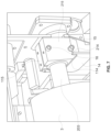
- FIG. 4 is a lateral view of the apparatus without covers
- FIG. 5 is a lateral view of the supporting system for rollers
- FIG. 6 is a front view of the lifting system for the applying roller
- FIG. 7 is an axonometric view of a detail of the supporting system for the applying roller
- FIG. 8 is an axonometric view of the roller coater provided with a bridge device for measuring panels thickness
- FIG. 9 is an axonometric view of the bridge device and a conveyor.
- roller coater indicated with the numeral 1 is generally a component of a more complex painting line, comprising other sundry (not shown) apparatuses placed upstream and downstream said roller coater 1 .
- said apparatus 1 there can be provided apparatuses for the pre-treatment of panels, while downstream there can be provided further apparatuses for applying further paint layers and/or ovens for drying/polymerizing the applied paint.
- FIG. 1 shows a roller coater 1 provided with the covers needed for its functioning without risk for human operators, as prescribed by the Machinery Directive 2006 / 42 /CE.
- the bold arrow shows the conveying direction of the glass panes to be painted.
- the roller coater 1 is provided with a cover 2 that is to be removed in order to reach an applying roller 3 .
- the cover is screwed with two screws to said roller coater 1 , screws that can be removed through an ordinary tool.
- Normally said roller coater 1 is provided with a PLC 27 having an interface that allows a human operator both to modify the set-up of the apparatus, and to detect the working parameters of said roller coater 1 .
- FIG. 2 shows the roller coater 1 , wherein said cover 2 was removed and the applying roller 3 in its working position.
- Said vertical cover 2 covers the applying roller 3 .
- a horizontal cover 6 covers both the applying roller 3 and a dosing roller 11 (visible in FIG. 4 ). Said applying roller 3 and said dosing roller 11 form an application head.
- the dosing roller 11 rotates in the conveying direction of the glass pane 8 (visible in FIG. 8 ).
- the applying roller 3 is a reverse roller, i.e., rotates in the opposite direction with respect to the conveying of the panes to be painted, and would tend to repel the glass pane, i.e., send it back to its place of origin.
- the inter-axis between said feed roller 9 and the applying roller 3 must be shorter than the minimum length of the shortest glass panel that can be coated in said roller coater. In this case, the distance is 600 mm.
- FIG. 3 shows a lateral view of said roller coater 1 , while said applying roller 3 is extracted through two straps 4 , each placed at one of its two ends.
- Said straps 4 are part of a lifting member, suitable for the weight of said roller 3 , which is around 200 kg.
- Said lifting member can be a bridge crane or a stacker, placed in a suitable point; the lifting member is independent from said roller coater 1 .
- Said lifting member is used also for inserting a new applying roller 3 into said roller coater 1 , in order to replace said worn/damaged roller 3 .
- the roller 3 can be replaced only when said roller coater is stopped (during downtimes).
- the positions of the rollers and of the covers of the roller coater 1 must be such, that the applying roller 3 can be extracted without entering into contact with other mechanical parts of the coater 1 .
- the dosing roller 11 undergoes a markedly lesser wear with respect to the applying roller 3 .
- the top cover 6 is removed, which opens like a door through a hinge 7 placed at the end of said cover 6 oriented to the entry of said panes.
- FIG. 4 shows a lateral view of the roller coater 1 , wherein the covers 2 , 5 and 6 were removed. Said removal allows to observe the feed roller 9 , which in use is hidden by said cover 5 , the applying roller 3 and the dosing roller 11 , which together form the application head, in use hidden by said cover 6 .
- the roller indicated with the numeral 3 ′ shows the position for the vertical extraction of said roller 3 . In other words, the roller indicated with 3 ′ is in the extraction position shown in FIG. 3 .
- the feed roller 9 rotates in the conveying direction of the glass panes, and is coupled to a contrast roller 39 .
- the applying roller 3 is a reverse roller and rotates in the direction opposite to the conveying direction.
- the dosing roller 11 rotates in the conveying direction.
- FIG. 4 allows to observe also a closed belt conveyor 12 , which is a component of the roller coater 1 .
- Said conveyor 12 is rectified; as customary, the closed belt rotates around two rollers, the first of which is an idle roller 31 , while the second roller is a motorized roller 32 .
- the applying roller 3 is a reverse roller, i.e., tends to repel the glass pane 8 , therefore there must be provided said feed roller 9 , which forces the pane across the applying roller 3 and the contrast roller 33 .
- the contrast roller 33 can be moved in the conveying direction, so that when it is moved from the vertical position with respect to the applying roller 3 , a too violent contact with the entry edge of the glass pane 8 is prevented.
- the conveying belt 12 is rectified in order to prevent surface bulging, due e.g., to a vulcanized joint, so as to prevent thickness differences along the belt.
- said differences in thickness provoke a difference of pressure of the applying roller 3 , and therefore a difference in the thickness of applied paint.
- the feed roller 9 presses on the glass pane 8 with an interference of about 0.5 mm.
- the glass pane 8 is intercepted by a photocell at the entry of the roller coater 1 , which accompanies it until said pane is held between said applying roller 3 and contrast roller 33 , with an interference of 0.5 mm again.
- the feed roller lifts from the glass pane 8 and the pane is dragged by the belt, in order to prevent vibrations during paint application.
- FIG. 5 shows a lateral view wherein all the covers were removed, and the support systems of said rollers are shown.
- Said application head comprising applying roller 3 and dosing roller 11 , moves with respect to the conveying belt 12 through two independent systems 13 provided with ball recirculating runners, one system on the right side and one system on the left side. In this way, it can adjust to the actual dimensions of the thickness of the glass pane 8 , which can be different on the two sides for some tenths of millimeter.
- the motorization is provided with brushless motors and encoder for the detection of position, with a centesimal precision.
- the feed roller 9 is provided with a similar lifting system, but without independent adjustment to the thickness on its two sides.
- the dosing of paint occurs through the pressure exerted by the dosing roller 11 on the applying roller 3 ; a stronger pressure decreases the quantity of applied paint.
- the speed of transport too, affects the applied quantity in an unwanted way: in fact, a greater speed of the glass panes 8 generally causes an increase of the quantity of applied paint.
- roller coaters typically the system for adjusting the quantity of applied paint occurs by varying the pressure applied to said dosing roller 11 .
- the dosing roller rotates in reverse, i.e., opposite to the conveying direction, and this leads to a removing of paint from said roller, altering the adjustment of the dosing roller; both can influence the quantity of applied paint.
- FIG. 6 shows the lifting member of the applying roller 3 for its replacement.
- said lifting member can be a bridge crane or a stacker suitably placed above said roller coater 1 .
- the lifting member is independent from said roller coater 1 .
- FIG. 7 shows a detail of the support for the applying roller 3 .
- said applying roller 3 is held by suitable supports 15 that fix the ball bearings on which the terminal ends 203 of the rotating shaft of the applying roller rotate.
- said supports 15 are two semi-clamps 115 and 215 that are locked through bolts 16 or through a combination of studs and nuts or other locking means.
- Each semi-clamp 115 , 215 is provided with an internal semi-circular annular surface, said semi-circular surface being divided on said two semi-clamps 115 , 215 according to a vertical section plane and radial with respect to the shaft 103 and to the relative ends 203 protruding from the heads of the applying roller 3 .
- said supports are opened, so separating said semi-clamps 115 , 215 , one of which, i.e., the one 115 oriented toward the pressing roller 9 , is stationary, while the other 215 is removable.
- the applying roller 3 can leave and separate from said semi-clamp 115 , and slides with its ends 203 on a corresponding guiding support provided on the roller coater 1 that defines a transferring path of the roller 3 and of its ends 203 in a position suitable for their grabbing through lifting means of said roller 3 .
- FIG. 7 shows an embodiment wherein said supports are in the form of a supporting bracket 14 provided with a top side 114 for supporting the corresponding end 203 of the shaft 103 of the roller.
- Said surface is substantially horizontal, preferably slightly tilted downwards, starting from an end that is provided at a level such that the supporting surface 114 is at the level of the horizontal tangent of the bottom side of the semi-circular room engaging said semi-clamp 115 .
- each bracket is provided with an end of stroke 214 , which in the shown embodiment is in the form of a prominence or tooth protruding upwards of the surface 114 .
- Such prominence or tooth has the purpose of preventing the fall of the roller 3 beyond the end of said brackets 14 once its supports are removed and the roller has slid along them. The roller is so stopped in the position wherein the applying roller 3 is free at its top from constructive parts of the apparatus 1 and can be lifted from the brackets as above shown and described with reference to FIG. 6 .
- FIGS. 5 - 7 The embodiment of FIGS. 5 - 7 is not limiting, but is only a preferred embodiment.
- FIG. 8 and FIG. 9 show the second embodiment of the present invention, in particular a bridge device 20 for measuring the thickness of glass panes 8 .
- the two Figures show the preferred placement for the bridge device 20 , i.e., upstream a closed belt conveying system 10 placed upstream said roller coater 1 .
- FIG. 8 shows a glass pane 8 that is inserted into the roller coater 1 through a closed belt conveyor 10 placed upstream said roller coater 1 .
- the bold arrow shows the conveying direction of the glass panes 8 .
- a bridge device 20 Upstream said closed belt conveyor 10 there is provided a bridge device 20 according to the second embodiment of the present invention. Said bridge device allows to measure the thickness of glass panes 8 during their conveyance through said bridge device, so that the data are sent in real time to the roller coater 1 , which adapts to the transmitted measures.
- FIG. 9 shows an axonometric view of said bridge device 20 , placed in proximity of the closed belt conveyor 10 .
- the bold arrow shows the conveying direction of the glass panes 8 .
- Said bridge device 20 comprises:
- glass panes especially when provided with a low thickness, are not provided with the same thickness on their right and left side, i.e., the sides parallel to the conveying direction of said panes 8 . Said difference can be of some tenths of millimeter.
- the working pressure of the applying roller 3 on the surface of the glass pane is very important for ensuring the uniformity of the paint layer.
- the bridge device 20 is not a component of the roller coater 1 and is fixed to the floor, preventing problems due to vibrations of the roller coater 1 during measuring.
- the bridge device 20 is independent from the roller coater 1 , nonetheless there is provided a communication system between the bridge device 20 and the PLC 27 of the roller coater 1 , allowing to transmit the actual thickness data of each pane 8 to the application head of the roller coater 1 in real time.
- the transversal position of the application head in the direction of width can be adjusted to the actual shape of the pane to be painted, in order to adapt it to the thickness difference between the two sides of the pane, using the above explained system with ball recirculating runners and brushless motor.
- the above description refers specifically to the use of said bridge device 20 for measuring the thickness of glass panes 8 inside a roller painting line for photovoltaic panels.
- the skilled man cannot miss the fact that any kind of mainly flat panel 8 can be painted in a line comprising the roller coater 1 according to the present invention, e.g., panels made of wood, plastics, fibrocement, etc.
- the skilled man cannot miss the fact that the bridge device 20 according to the present invention can be used in a production line comprising machines of any type working in contact with a main surface of said panel 8 , e.g., machines for cleaning said main surface, or sanding machines.
Landscapes
- Physics & Mathematics (AREA)
- General Physics & Mathematics (AREA)
- Coating Apparatus (AREA)
- Photovoltaic Devices (AREA)
- Application Of Or Painting With Fluid Materials (AREA)
Abstract
Description
-
- A
frame 21 provide withfeet 22 for fixing it to the floor, so that thebridge device 20 is independent and can be placed in the most suitable points of the painting line. In this way, bumps and/or vibrations generated by the movement of the rotating organs are prevented, which might affect the precision of measuring; -
Supports 23 supporting contact sensors; said supports can be slid in a direction which is perpendicular to the conveying direction of thepanes 8 to be painted, in order to adapt their position to the transversal measure (width) of theglass pane 8; - Contact sensors 24 (one for each side of the glass); said
sensor 24 are divided into two parts, a top part and a bottom part with respect to the surface of theglass pane 8, and are both provided with a pneumatic cylinder, in its turn integral with an encoder detecting the displacement while leaning on the surface through an idle roller; - Transversal photocells 25, detecting the position of the
glass pane 8 and its length; - Blocking knobs 26 for blocking said supports 23.
- A
-
- (a) The
glass pane 8 conveyed in the painting line is intercepted by thephotocells 25, activating the measuringsensors 24; - (b) When the
glass pane 8 detected by the photocells reaches the twosensors 24, said pneumatic cylinders bring said idle roller in contact with the top and bottom surfaces of the glass pane, and by value difference the actual thickness of the pane is measured; - (c) The measure is transmitted to the
PLC 27 of theroller coater 1, which manages the positioning of the application head; - (d) Through two independent motorizations for positioning each of the two sides of the
roller 3, said roller can be adjusted to the actual thickness of the glass pane, and with the working pressure optimal for a correct paint application on both sides; - (e) When the
photocells 25 detect the end of the glass pane, they send a signal to the measuringsensors 24, which deactivate.
- (a) The
-
- 1 roller coater
- 2 cover
- 3 applying roller
- 4 strap
- 5 cover for the feed roller
- 6 cover
- 7 hinge
- 8 glass pane
- 9 feed roller
- 10 closed belt conveyor
- 11 dosing roller
- 12 rectified conveyor
- 13 ball recirculating runners system
- 14 bracket
- 15 support for the applying roller
- 16 screw
- 20 bridge device
- 21 frame
- 22 feet for fixing to floor
- 23 supports for measuring sensors
- 24 contact sensors
- 25 transversal photocell
- 26 blocking knob
- 27 PLC
- 31 idle roller
- 32 motorized roller
- 33 contrast roller
- 39 contrast roller
- 103 rotation shaft of the applying roller
- 203 end of the rotation shaft
- 114 top side of brackets
- 214 end of stroke
- 115 semi-clamp
- 215 semi-clamp
Claims (10)
Applications Claiming Priority (2)
| Application Number | Priority Date | Filing Date | Title |
|---|---|---|---|
| IT102021000013085 | 2021-05-20 | ||
| IT102021000013085A IT202100013085A1 (en) | 2021-05-20 | 2021-05-20 | APPARATUS AND METHOD FOR PAINTING PANELS BY ROLLER, PREFERABLE PHOTOVOLTAIC PANELS |
Publications (2)
| Publication Number | Publication Date |
|---|---|
| US20220371042A1 US20220371042A1 (en) | 2022-11-24 |
| US12036572B2 true US12036572B2 (en) | 2024-07-16 |
Family
ID=77412093
Family Applications (1)
| Application Number | Title | Priority Date | Filing Date |
|---|---|---|---|
| US17/744,672 Active US12036572B2 (en) | 2021-05-20 | 2022-05-15 | Apparatus and method for applying paint with roller coaters, preferably to photovoltaic panels |
Country Status (4)
| Country | Link |
|---|---|
| US (1) | US12036572B2 (en) |
| EP (1) | EP4091723B1 (en) |
| CN (1) | CN115365050A (en) |
| IT (1) | IT202100013085A1 (en) |
Families Citing this family (1)
| Publication number | Priority date | Publication date | Assignee | Title |
|---|---|---|---|---|
| IT202100013085A1 (en) * | 2021-05-20 | 2022-11-20 | Cefla Soc Cooperativa | APPARATUS AND METHOD FOR PAINTING PANELS BY ROLLER, PREFERABLE PHOTOVOLTAIC PANELS |
Citations (22)
| Publication number | Priority date | Publication date | Assignee | Title |
|---|---|---|---|---|
| US5297568A (en) * | 1991-03-08 | 1994-03-29 | Gebr. Schmid Gbmh & Co. | Process and apparatus for treatment of board-like articles |
| US5976256A (en) * | 1996-11-27 | 1999-11-02 | Tokyo Electron Limited | Film coating apparatus |
| US6139639A (en) * | 1994-12-28 | 2000-10-31 | Toray Industries, Inc. | Coating machine having a timer for continuously forming a coating of uniform thickness on a substrate |
| US6258167B1 (en) * | 1996-11-27 | 2001-07-10 | Tokyo Electron Limited | Process liquid film forming apparatus |
| US6540833B1 (en) * | 1998-01-09 | 2003-04-01 | Fastar, Ltd. | Moving head coating apparatus and method |
| US20090229516A1 (en) * | 2008-03-13 | 2009-09-17 | Sorbini Roberto | Combined machine, particularly for painting sheets of glass, crystal or other flat surfaces in general |
| US7905195B2 (en) * | 2005-07-19 | 2011-03-15 | Tokyo Electron Limited | Floating-type substrate conveying and processing apparatus |
| US8079662B2 (en) * | 2006-04-19 | 2011-12-20 | Sharp Kabushiki Kaisha | Drop coating apparatus |
| US8196543B2 (en) * | 2006-04-21 | 2012-06-12 | Sharp Kabushiki Kaisha | Defect repairing apparatus, defect repairing method, program, and computer-readable recording medium |
| US8230804B1 (en) * | 2008-09-03 | 2012-07-31 | P&B Construction, Inc. | Enclosed chamber, adjustable finish-applicator for flat and dimensional surfaces |
| US8681345B2 (en) * | 2010-03-25 | 2014-03-25 | First Solar, Inc. | System and method for measuring photovoltaic module thickness |
| US8733275B2 (en) * | 2005-03-11 | 2014-05-27 | Toray Industries, Inc. | Application apparatus, application method and method for manufacturing web having coating film |
| US9314811B1 (en) | 2015-05-11 | 2016-04-19 | Enki Technology, Inc. | Coating and curing apparatus and methods |
| US9393594B2 (en) * | 2012-03-07 | 2016-07-19 | Forjak Industrial Llc | System and method for painting a structure |
| CN106423711A (en) | 2016-08-30 | 2017-02-22 | 安徽纪兴源科技股份有限公司 | Single-roller coating machine capable of being suitable for non-planar plate |
| US9951450B2 (en) * | 2013-07-15 | 2018-04-24 | Armacell Jios Aerogels Limited | System for injecting functional solution for fabric and method for manufacturing fabric using same |
| CN110918370A (en) | 2019-12-05 | 2020-03-27 | 东莞云展智能装备有限公司 | Automatic wipe processing agent equipment |
| US20210016314A1 (en) * | 2018-03-28 | 2021-01-21 | Biemme Elettrica Di Bertola Massimo | Device for Coating, in Particular Painting, the Main Surfaces of Rigid Panels with Liquid Products |
| CN112275531A (en) | 2020-09-19 | 2021-01-29 | 佛山市顺涂科技有限公司 | Plate scraping and coating machine |
| US20220371042A1 (en) * | 2021-05-20 | 2022-11-24 | CEFLA Società Cooperativa | Apparatus and method for applying paint with roller coaters, preferable to photovoltaic panels |
| US20220371947A1 (en) * | 2021-05-20 | 2022-11-24 | CEFLA Società Cooperativa | Apparatus and method for applying paint with roller coaters, preferably to photovoltaic panels |
| US20220379339A1 (en) * | 2021-03-04 | 2022-12-01 | Kabushiki Kaisha Toshiba | Coating apparatus and coating method |
-
2021
- 2021-05-20 IT IT102021000013085A patent/IT202100013085A1/en unknown
-
2022
- 2022-05-10 EP EP22172451.1A patent/EP4091723B1/en active Active
- 2022-05-15 US US17/744,672 patent/US12036572B2/en active Active
- 2022-05-19 CN CN202210557792.7A patent/CN115365050A/en active Pending
Patent Citations (24)
| Publication number | Priority date | Publication date | Assignee | Title |
|---|---|---|---|---|
| US5297568A (en) * | 1991-03-08 | 1994-03-29 | Gebr. Schmid Gbmh & Co. | Process and apparatus for treatment of board-like articles |
| US6139639A (en) * | 1994-12-28 | 2000-10-31 | Toray Industries, Inc. | Coating machine having a timer for continuously forming a coating of uniform thickness on a substrate |
| US5976256A (en) * | 1996-11-27 | 1999-11-02 | Tokyo Electron Limited | Film coating apparatus |
| US6258167B1 (en) * | 1996-11-27 | 2001-07-10 | Tokyo Electron Limited | Process liquid film forming apparatus |
| US6540833B1 (en) * | 1998-01-09 | 2003-04-01 | Fastar, Ltd. | Moving head coating apparatus and method |
| US20030118741A1 (en) * | 1998-01-09 | 2003-06-26 | Gibson Gregory M. | Moving head, coating method |
| US8733275B2 (en) * | 2005-03-11 | 2014-05-27 | Toray Industries, Inc. | Application apparatus, application method and method for manufacturing web having coating film |
| US7905195B2 (en) * | 2005-07-19 | 2011-03-15 | Tokyo Electron Limited | Floating-type substrate conveying and processing apparatus |
| US8079662B2 (en) * | 2006-04-19 | 2011-12-20 | Sharp Kabushiki Kaisha | Drop coating apparatus |
| US8196543B2 (en) * | 2006-04-21 | 2012-06-12 | Sharp Kabushiki Kaisha | Defect repairing apparatus, defect repairing method, program, and computer-readable recording medium |
| US20090229516A1 (en) * | 2008-03-13 | 2009-09-17 | Sorbini Roberto | Combined machine, particularly for painting sheets of glass, crystal or other flat surfaces in general |
| US8230804B1 (en) * | 2008-09-03 | 2012-07-31 | P&B Construction, Inc. | Enclosed chamber, adjustable finish-applicator for flat and dimensional surfaces |
| US8681345B2 (en) * | 2010-03-25 | 2014-03-25 | First Solar, Inc. | System and method for measuring photovoltaic module thickness |
| US9393594B2 (en) * | 2012-03-07 | 2016-07-19 | Forjak Industrial Llc | System and method for painting a structure |
| US9951450B2 (en) * | 2013-07-15 | 2018-04-24 | Armacell Jios Aerogels Limited | System for injecting functional solution for fabric and method for manufacturing fabric using same |
| US9314811B1 (en) | 2015-05-11 | 2016-04-19 | Enki Technology, Inc. | Coating and curing apparatus and methods |
| CN106423711A (en) | 2016-08-30 | 2017-02-22 | 安徽纪兴源科技股份有限公司 | Single-roller coating machine capable of being suitable for non-planar plate |
| US11660632B2 (en) * | 2018-03-28 | 2023-05-30 | Ecosys S.R.L. | Device for coating, in particular painting, the main surfaces of rigid panels with liquid products |
| US20210016314A1 (en) * | 2018-03-28 | 2021-01-21 | Biemme Elettrica Di Bertola Massimo | Device for Coating, in Particular Painting, the Main Surfaces of Rigid Panels with Liquid Products |
| CN110918370A (en) | 2019-12-05 | 2020-03-27 | 东莞云展智能装备有限公司 | Automatic wipe processing agent equipment |
| CN112275531A (en) | 2020-09-19 | 2021-01-29 | 佛山市顺涂科技有限公司 | Plate scraping and coating machine |
| US20220379339A1 (en) * | 2021-03-04 | 2022-12-01 | Kabushiki Kaisha Toshiba | Coating apparatus and coating method |
| US20220371042A1 (en) * | 2021-05-20 | 2022-11-24 | CEFLA Società Cooperativa | Apparatus and method for applying paint with roller coaters, preferable to photovoltaic panels |
| US20220371947A1 (en) * | 2021-05-20 | 2022-11-24 | CEFLA Società Cooperativa | Apparatus and method for applying paint with roller coaters, preferably to photovoltaic panels |
Also Published As
| Publication number | Publication date |
|---|---|
| IT202100013085A1 (en) | 2022-11-20 |
| EP4091723A1 (en) | 2022-11-23 |
| EP4091723B1 (en) | 2026-02-11 |
| CN115365050A (en) | 2022-11-22 |
| US20220371042A1 (en) | 2022-11-24 |
Similar Documents
| Publication | Publication Date | Title |
|---|---|---|
| US12036572B2 (en) | Apparatus and method for applying paint with roller coaters, preferably to photovoltaic panels | |
| EP4092374B1 (en) | Apparatus and method for measuring the thickness of panels | |
| CN112109967B (en) | Fully automatic aluminum substrate lamination and leveling production line | |
| KR101695566B1 (en) | Space control device of heating roller in laminator | |
| EP2460410B1 (en) | Device and method for lapping dough | |
| CN111169940A (en) | Device and method for detecting slippage of conveying belt of belt conveyor | |
| CN109675966A (en) | A kind of shear machine testing smoothing feeding mechanism | |
| KR102198948B1 (en) | Conveyor device for changing direction of conveyed article | |
| CN211997567U (en) | Device for detecting slippage of conveying belt of belt conveyor | |
| CN106563610B (en) | Roll coater | |
| CN219785446U (en) | Coating machine convenient to control coating thickness | |
| CN217707488U (en) | Automatic deviation correcting device of short high-speed belt conveyor | |
| US3365844A (en) | Abrasive belt handling device | |
| EP4200087B1 (en) | A contact cleaning apparatus | |
| CN114906655A (en) | Tension control device in paperboard transmission | |
| CN209476987U (en) | A kind of shear machine testing smoothing feeding mechanism | |
| CN218502724U (en) | Reinspection machine with guider | |
| CN220536710U (en) | Broad width conveying device for dust removal of laminating machine | |
| CN218641764U (en) | Material conveying equipment | |
| CN220104889U (en) | Injection molding gap detection equipment | |
| KR101377519B1 (en) | Tension device for preventing deviation of belt conveyor | |
| CN222661325U (en) | Width measuring device of medium plate shot blasting equipment | |
| CN220611373U (en) | Weighing mechanism of automatic conveyor | |
| CN222311855U (en) | A product posture adjustment structure for a conveyor belt | |
| JPH05111653A (en) | Adhesive applying device |
Legal Events
| Date | Code | Title | Description |
|---|---|---|---|
| FEPP | Fee payment procedure |
Free format text: ENTITY STATUS SET TO UNDISCOUNTED (ORIGINAL EVENT CODE: BIG.); ENTITY STATUS OF PATENT OWNER: LARGE ENTITY |
|
| AS | Assignment |
Owner name: CEFLA SOCIETA COOPERATIVA, ITALY Free format text: ASSIGNMENT OF ASSIGNORS INTEREST;ASSIGNOR:FILIPPINI, FABRIZIO;REEL/FRAME:060154/0499 Effective date: 20220609 |
|
| STPP | Information on status: patent application and granting procedure in general |
Free format text: DOCKETED NEW CASE - READY FOR EXAMINATION |
|
| STPP | Information on status: patent application and granting procedure in general |
Free format text: NON FINAL ACTION MAILED |
|
| STPP | Information on status: patent application and granting procedure in general |
Free format text: RESPONSE TO NON-FINAL OFFICE ACTION ENTERED AND FORWARDED TO EXAMINER |
|
| STPP | Information on status: patent application and granting procedure in general |
Free format text: NON FINAL ACTION MAILED |
|
| STPP | Information on status: patent application and granting procedure in general |
Free format text: NOTICE OF ALLOWANCE MAILED -- APPLICATION RECEIVED IN OFFICE OF PUBLICATIONS |
|
| STPP | Information on status: patent application and granting procedure in general |
Free format text: PUBLICATIONS -- ISSUE FEE PAYMENT RECEIVED |
|
| STPP | Information on status: patent application and granting procedure in general |
Free format text: PUBLICATIONS -- ISSUE FEE PAYMENT VERIFIED |
|
| STCF | Information on status: patent grant |
Free format text: PATENTED CASE |