US12032146B2 - Camera lens system - Google Patents
Camera lens system Download PDFInfo
- Publication number
- US12032146B2 US12032146B2 US17/278,251 US201917278251A US12032146B2 US 12032146 B2 US12032146 B2 US 12032146B2 US 201917278251 A US201917278251 A US 201917278251A US 12032146 B2 US12032146 B2 US 12032146B2
- Authority
- US
- United States
- Prior art keywords
- prism
- optical system
- axis
- folded optical
- recited
- Prior art date
- Legal status (The legal status is an assumption and is not a legal conclusion. Google has not performed a legal analysis and makes no representation as to the accuracy of the status listed.)
- Active, expires
Links
- 230000003287 optical effect Effects 0.000 claims abstract description 124
- 239000000463 material Substances 0.000 claims abstract description 17
- 238000000034 method Methods 0.000 description 8
- 238000003384 imaging method Methods 0.000 description 6
- 238000004891 communication Methods 0.000 description 5
- 230000002093 peripheral effect Effects 0.000 description 5
- 238000005516 engineering process Methods 0.000 description 3
- 238000004519 manufacturing process Methods 0.000 description 3
- 238000012986 modification Methods 0.000 description 3
- 230000004048 modification Effects 0.000 description 3
- 238000012545 processing Methods 0.000 description 3
- 238000007792 addition Methods 0.000 description 2
- 230000004075 alteration Effects 0.000 description 2
- 230000008901 benefit Effects 0.000 description 2
- 230000005540 biological transmission Effects 0.000 description 2
- 238000010586 diagram Methods 0.000 description 2
- 230000000694 effects Effects 0.000 description 2
- 230000007613 environmental effect Effects 0.000 description 2
- 239000000835 fiber Substances 0.000 description 2
- 230000006870 function Effects 0.000 description 2
- 229920003023 plastic Polymers 0.000 description 2
- 230000009471 action Effects 0.000 description 1
- 239000003795 chemical substances by application Substances 0.000 description 1
- 239000011248 coating agent Substances 0.000 description 1
- 238000000576 coating method Methods 0.000 description 1
- 238000013501 data transformation Methods 0.000 description 1
- 238000013461 design Methods 0.000 description 1
- 230000010354 integration Effects 0.000 description 1
- 238000007726 management method Methods 0.000 description 1
- 238000004806 packaging method and process Methods 0.000 description 1
- 229920001690 polydopamine Polymers 0.000 description 1
- 230000009467 reduction Effects 0.000 description 1
- 239000004065 semiconductor Substances 0.000 description 1
- 239000010454 slate Substances 0.000 description 1
- 230000003068 static effect Effects 0.000 description 1
- 229920000638 styrene acrylonitrile Polymers 0.000 description 1
- 230000001360 synchronised effect Effects 0.000 description 1
- 230000002123 temporal effect Effects 0.000 description 1
Images


Classifications
-
- G—PHYSICS
- G02—OPTICS
- G02B—OPTICAL ELEMENTS, SYSTEMS OR APPARATUS
- G02B13/00—Optical objectives specially designed for the purposes specified below
- G02B13/001—Miniaturised objectives for electronic devices, e.g. portable telephones, webcams, PDAs, small digital cameras
- G02B13/0055—Miniaturised objectives for electronic devices, e.g. portable telephones, webcams, PDAs, small digital cameras employing a special optical element
- G02B13/0065—Miniaturised objectives for electronic devices, e.g. portable telephones, webcams, PDAs, small digital cameras employing a special optical element having a beam-folding prism or mirror
- G02B13/007—Miniaturised objectives for electronic devices, e.g. portable telephones, webcams, PDAs, small digital cameras employing a special optical element having a beam-folding prism or mirror the beam folding prism having at least one curved surface
-
- G—PHYSICS
- G02—OPTICS
- G02B—OPTICAL ELEMENTS, SYSTEMS OR APPARATUS
- G02B17/00—Systems with reflecting surfaces, with or without refracting elements
- G02B17/08—Catadioptric systems
- G02B17/0856—Catadioptric systems comprising a refractive element with a reflective surface, the reflection taking place inside the element, e.g. Mangin mirrors
-
- G—PHYSICS
- G02—OPTICS
- G02B—OPTICAL ELEMENTS, SYSTEMS OR APPARATUS
- G02B5/00—Optical elements other than lenses
- G02B5/04—Prisms
Definitions
- Embodiments of the present disclosure may provide a folded optical system that may, for example, be used as a camera lens in small form factor cameras.
- Embodiments of a folded optical system are described that include two prisms with refractive power that together form the optical system.
- At least one surface of at least one of the prisms is a “freeform” surface, and thus the prism(s) may be referred to as freeform prisms.
- a freeform prism may be broadly defined as a prism with at least one surface that provides refractive power and that is asymmetric (not rotationally symmetric) (i.e., is a “freeform” surface).
- the prisms provide a “folded” optical axis for the camera, for example to reduce the Z-height of the camera.
- At least one surface of at least one of the prisms is a freeform surface.
- at least two of the six surfaces of the prisms in the optical system are freeform surfaces.
- the first and third surfaces in both prisms are freeform surfaces, while the second surfaces in both prisms are flat/plano.
- one or both of the second surfaces may be freeform surfaces with refractive power or symmetrical surfaces with refractive power.
- FOV full field of view
- an aperture stop is located in the optical system at the first (object side) surface of the first prism.
- the aperture stop may be elliptical; however, circular or other shapes may be used for the aperture in some embodiments.
- the folded camera may include an infrared (IR) filter to reduce or eliminate interference of environmental noise on the photosensor.
- the IR filter may, for example, be located between the second prism and the photosensor.
- FIG. 1 illustrates a conventional folded lens system that includes a lens stack positioned between two prisms.
- FIG. 2 illustrates a folded optical system that consists of two freeform prisms, according to some embodiments.
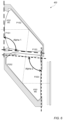
- FIGS. 3 A, 3 B, and 3 C are diagrams illustrating orientation of the x and y axes at the surfaces of the freeform prisms as shown in FIG. 2 , according to some embodiments.
- FIG. 4 is a 3D cross-sectional illustration of a folded optical system that includes two freeform prisms, according to some embodiments.
- FIG. 7 is a flowchart of a method for capturing images using embodiments of a folded optical system as illustrated in FIGS. 2 through 6 , according to some embodiments.
- a unit/circuit/component is “configured to” perform one or more tasks is expressly intended not to invoke 35 U.S.C. ⁇ 112, sixth paragraph, for that unit/circuit/component.
- “configured to” can include generic structure (e.g., generic circuitry) that is manipulated by software and/or firmware (e.g., an FPGA or a general-purpose processor executing software) to operate in manner that is capable of performing the task(s) at issue.
- “Configure to” may also include adapting a manufacturing process (e.g., a semiconductor fabrication facility) to fabricate devices (e.g., integrated circuits) that are adapted to implement or perform one or more tasks.
- Second “First,” “Second,” etc. As used herein, these terms are used as labels for nouns that they precede, and do not imply any type of ordering (e.g., spatial, temporal, logical, etc.).
- a buffer circuit may be described herein as performing write operations for “first” and “second” values.
- the terms “first” and “second” do not necessarily imply that the first value must be written before the second value.
- this term is used to describe one or more factors that affect a determination. This term does not foreclose additional factors that may affect a determination. That is, a determination may be solely based on those factors or based, at least in part, on those factors.
- a determination may be solely based on those factors or based, at least in part, on those factors.
- Embodiments of a folded optical system include two prisms with refractive power that together form the optical system. At least one surface of at least one of the prisms is a “freeform” surface, and thus the prism(s) may be referred to as freeform prisms.
- a freeform prism may be broadly defined as a prism with at least one surface that provides refractive power and that is asymmetric (not rotationally symmetric) (i.e., is a “freeform” surface).
- Embodiments of the folded optical system as described herein may be implemented in a small package size while still capturing sharp, high-resolution images, making embodiments of a camera including the optical system suitable for use in small and/or mobile multipurpose devices such as cell phones, smartphones, pad or tablet computing devices, laptop, netbook, notebook, subnotebook, and ultrabook computers, and so on.
- FIG. 8 illustrates an example device that may include one or more small form factor cameras that use embodiments of the folded optical system as described herein.
- aspects of the camera e.g., the optical system and photosensor
- embodiments of the camera may be implemented as stand-alone digital cameras.
- embodiments of the camera may be adapted for use in video camera applications.
- FIG. 1 illustrates a conventional folded camera 100 that includes a lens stack positioned between two prisms, according to some embodiments.
- the prisms 141 and 142 provide a “folded” optical axis for the camera 100 , for example to reduce the Z-height of the camera 100 when compared to conventional straight camera lenses.
- a lens stack 114 including one or more refractive lens elements is located between prisms 141 and 142 .
- a first prism 141 redirects light from an object field from a first axis to the lens stack 114 on a second axis.
- the lens element(s) in the lens stack 114 refract the light to a second prism 142 that redirects the light onto a third axis on which a photosensor 120 of the camera 100 is disposed.
- the redirected light forms an image at an image plane 121 at or near the surface of the photosensor 120 .
- FIG. 2 illustrates a camera 200 that includes a folded optical system that consists of two freeform prisms 241 and 242 with refractive power, according to some embodiments.
- the prisms 241 and 242 provide a “folded” optical axis for the camera 200 , for example to reduce the Z-height of the camera.
- a camera 100 with a conventional folded lens system as illustrated in FIG. 1 may have a Z-axis height of >6 mm, for example 6.4 mm
- a camera 200 with a folded optical system as illustrated in FIG. 2 may have a Z-axis height of ⁇ 6 mm, for example 5.4 mm, while providing similar performance to the camera 100 of FIG. 1 .
- the freeform prisms 241 and 242 in the folded optical system of camera 200 may eliminate the need for a lens stack between the prisms as shown in the camera 100 of FIG. 1 , which may reduce the length of the long axis of the camera 200 when compared to the camera 100 of FIG. 1 .
- the folded optical system of FIG. 2 requires fewer optical elements (two freeform prism) when compared to the folded lens system of FIG. 1 (two prisms and at least one refractive lens element in the lens stack). Having fewer optical elements may, for example, simplify packaging and alignment of the optical system during manufacture when compared to the lens system of FIG. 1 .
- a first freeform prism 241 receives light from an object field through an aperture stop 230 and refracts and redirects the light from a first axis to a second axis.
- Prism 241 includes three surfaces that affect light passing through the prism 241 .
- a first surface (P 1 S 1 ) refracts light received from an object field through aperture stop 230 ;
- a second surface (P 1 S 2 ) reflects or redirects the light to a third surface (P 1 S 3 ); the light is refracted by the third surface to the second prism 242 .
- a second freeform prism 242 receives the light on the second axis and refracts and redirects the light onto a third axis on which a photosensor 220 of the camera is disposed.
- the refracted and redirected light forms an image at an image plane 221 at or near the surface of the photosensor 220 .
- Prism 242 includes three surfaces that affect light passing through the prism 242 .
- a first surface (P 2 S 1 ) refracts light received from the first prism 241 ; a second surface (P 2 S 2 ) reflects or redirects the light to a third surface (P 2 S 3 ); the light is refracted by the third surface to form an image at an image plane 221 at or near the surface of the photosensor 220 .
- an infrared (IR) filter 250 may be located between the second prism 242 and the photosensor 220 .
- a given surface may be flat/plano with no refractive power; symmetrically concave, convex, or aspherical with refractive power; or freeform (asymmetrically concave, convex, or aspherical with refractive power).
- at least one surface of at least one of the prisms is a freeform surface.
- at least two of the six surfaces of the prisms in the optical system are freeform surfaces.
- the first and third surfaces in both prisms are freeform surfaces, while the second surfaces in both prisms are flat/plano.
- one or both of the second surfaces may be freeform surfaces with refractive power or symmetrical surfaces with refractive power.
- FOV full field of view
- an aperture stop 230 is located in the folded optical system at the first (object side) surface of the first prism 241 .
- the aperture stop 230 may be elliptical; however, circular or other shapes may be used for the aperture in some embodiments.
- the camera 200 may include an infrared (IR) filter 250 to reduce or eliminate interference of environmental noise on the photosensor 220 .
- the IR filter 250 may, for example, be located between the second prism 242 and the photosensor 220 .
- FIGS. 3 A, 3 B, and 3 C are diagrams illustrating orientation of the x and y axes at the surfaces of the freeform prisms as shown in FIG. 2 , according to some embodiments.
- FIG. 3 A is s cross-sectional illustration of a folded optical system, according to some embodiments.
- optical characteristics of the freeform surfaces of the prisms in an optical system as illustrated in FIG. 2 may be defined for a paraxial region of the surfaces along two axes of symmetry (x and y) relative to the optical axis at the surfaces of the prisms 241 and 242 . As shown in FIG.
- the y axis and the optical axis are on the plane of the cross-section, and the x axis is perpendicular to the plane of the cross-section.
- the x axis is on a tangent plane at the intersection of the optical axis with the surface and is parallel to the x axis at the photosensor 220 and perpendicular to the optical axis.
- the y axis rotates around the x axis to conform to the tangent plane, and thus is not necessarily parallel to the y axis at the photosensor 220 .
- the aperture stop 230 may be elliptical; however, circular or other shapes may be used for the aperture in some embodiments.
- FIG. 3 C shows the x and y axes at the aperture as previously defined at the surface.
- the paraxial region is a region around the optical axis that extends 10% or less of the width of the aperture in each direction from the optical axis on the x and y axes.
- FIG. 4 is a 3D cross-sectional illustration of an example folded optical system that includes two freeform prisms, according to some embodiments.
- a telephoto camera 400 may include a folded optical system that consists of two freeform prisms 441 and 442 .
- An aperture stop may be located at a first (object side) surface of the first prism 441 .
- the aperture stop may be elliptical or circular.
- the camera 400 also includes a photosensor 420 .
- an infrared filter may be located between the second prism 442 and the photosensor.
- FOV full field of view
- the folded optical system consists of two freeform prisms 441 (P 1 ) and 442 (P 2 ).
- Each of the two prisms 441 and 442 includes three surfaces that affect light passing through the prism.
- a first surface (S 1 ) receives the light from an object side of the prism;
- a second surface (S 2 ) reflects or redirects the light received through the first surface to a third surface (S 3 ); the light then passes through or is refracted by the third surface to the next prism or to the photosensor 420 .
- Each of the prisms includes at least one freeform surface in the imaging path that is not rotationally symmetric.
- the aperture stop 430 of the folded optical system is at or near the object side surface (P 1 S 1 ) of prism 441 . In some embodiments, the aperture stop 430 is at or near (within 0.3 mm) surface P 1 S 1 for imaging purposes.
- the folded optical system has same focal lengths along the x axis and along the y axis.
- focal lengths along the x axis are different than focal lengths along the y axis (f P1Y , f P2Y ), respectively, which defines both prisms 441 and 442 as freeform prisms: f P1X ⁇ f P1Y ,f P2X ⁇ f P2Y .
- an optional infrared cutoff filter is positioned in front of the photosensor 420 to remove unwanted infrared light and thus improve the signal-to-noise ratio (SNR).
- P 1 S 2 is reflective coated to reflect visible light and fold the optical axis.
- P 1 S 3 is convex in the paraxial region, and satisfies the following conditions: 1 ⁇ f P1S3x /f P1x ⁇ 3 4 ⁇ f P1S3y /f P1y ⁇ 5 where f P1S3y and f P1S3x are focal lengths of surface P 1 S 3 on they and x axes, respectively.
- Prism 442 has three surfaces along the optical axis from an object side to an image side: P 2 S 1 , P 2 S 2 , and P 2 S 3 .
- P 2 S 1 is concave in the paraxial region, and satisfies the following conditions: 1 ⁇ f P2S1y /f P2y f P2S1x /f P2x ⁇ 3 where f P2S1y and f P2S1x are focal lengths of surface P 2 S 1 on they and x axes, respectively.
- prism 442 may be formed of an optical plastic material. In some embodiments, prism 442 is formed of an optical material with an Abbe number vd2 that satisfies the following condition: vd 2 ⁇ 30
- FIG. 6 is a cross-sectional illustration of an example folded optical system that includes two freeform prisms and shows the angles between surfaces of the freeform prisms, according to some embodiments.
- the angle between the tangent line of P 1 S 1 and the tangent line of P 1 S 3 is Alpha 1.
- Alpha 1 satisfies the following condition: 70 degrees ⁇ Alpha 1 ⁇ 110 degrees
- the angle between the tangent line of P 2 S 1 and the tangent line of P 2 S 3 is Alpha 2.
- Alpha 2 satisfies the following condition: 70 degrees ⁇ Alpha 2 ⁇ 110 degrees
- the methods described herein may be implemented in software, hardware, or a combination thereof, in different embodiments.
- the order of the blocks of the methods may be changed, and various elements may be added, reordered, combined, omitted, modified, etc.
- Various modifications and changes may be made as would be obvious to a person skilled in the art having the benefit of this disclosure.
- the various embodiments described herein are meant to be illustrative and not limiting. Many variations, modifications, additions, and improvements are possible. Accordingly, plural instances may be provided for components described herein as a single instance. Boundaries between various components, operations and data stores are somewhat arbitrary, and particular operations are illustrated in the context of specific illustrative configurations.
Landscapes
- Physics & Mathematics (AREA)
- General Physics & Mathematics (AREA)
- Optics & Photonics (AREA)
- Lenses (AREA)
- Optical Elements Other Than Lenses (AREA)
Abstract
Description
f x =f y =f sys,
where fx is the focal length through the folded optical system on the x axis, fy is the focal length through the folded optical system on they axis, and fsys is the effective focal length of the folded optical system.
f P1X ≠f P1Y ,f P2X ≠f P2Y.
0.55<f P1y /f sys<0.85
0.5<f P1x /f sys<0.8
where fP1y is the focal length of
1.2<f P1S1y /f P1y
f P1S1x /f P1x<2.8
where fP1S1y and fP1S1x are focal lengths of surface P1S1 on they and x axes, respectively.
1<f P1S3x /f P1x<3
4<f P1S3y /f P1y<5
where fP1S3y and fP1S3x are focal lengths of surface P1S3 on they and x axes, respectively.
vd1>50.
−1<f P2y /f sys<−0.4
−1<f P2x /f sys<−0.7
where fP2y is the focal length of
1<f P2S1y /f P2y
f P2S1x /f P2x<3
where fP2S1y and fP2S1x are focal lengths of surface P2S1 on they and x axes, respectively.
3<f P2S3x /f P2y<7
1<f P2S3y /f P2y<3
where fP2S3y and fP2S3x are focal lengths of surface P2S3 on the y and x axes, respectively.
vd2<30
70 degrees<
70 degrees<
Example Flowchart
Claims (20)
f x =f y =f sys,
0.55<f P1y /f sys<0.85,
0.5<f P1x /f sys<0.8,
1.2<f P1S1y /f P1y,
f P1S1x /f P1x<2.8,
1<f P1S3x /f P1x<3,
4<f P1S3y /f P1y<5,
−1<f P2y /f sys<−0.4,
−1<f P2x /f sys<−0.7,
1<f P2S1y /f P2y,
f P2S1x /f P2x<3,
3<f P2S3x /f P2y<7,
1<f P2S3y /f P2y<3,
70 degrees<Alpha 1<110 degrees,
70 degrees<Alpha 2<110 degrees,
Priority Applications (1)
| Application Number | Priority Date | Filing Date | Title |
|---|---|---|---|
| US17/278,251 US12032146B2 (en) | 2018-09-25 | 2019-09-20 | Camera lens system |
Applications Claiming Priority (3)
| Application Number | Priority Date | Filing Date | Title |
|---|---|---|---|
| US201862736394P | 2018-09-25 | 2018-09-25 | |
| US17/278,251 US12032146B2 (en) | 2018-09-25 | 2019-09-20 | Camera lens system |
| PCT/US2019/052244 WO2020068594A1 (en) | 2018-09-25 | 2019-09-20 | Camera lens system |
Publications (2)
| Publication Number | Publication Date |
|---|---|
| US20210349295A1 US20210349295A1 (en) | 2021-11-11 |
| US12032146B2 true US12032146B2 (en) | 2024-07-09 |
Family
ID=68136567
Family Applications (1)
| Application Number | Title | Priority Date | Filing Date |
|---|---|---|---|
| US17/278,251 Active 2039-10-05 US12032146B2 (en) | 2018-09-25 | 2019-09-20 | Camera lens system |
Country Status (7)
| Country | Link |
|---|---|
| US (1) | US12032146B2 (en) |
| EP (1) | EP3857282B1 (en) |
| KR (1) | KR102814840B1 (en) |
| CN (1) | CN112714885A (en) |
| AU (1) | AU2019346376C1 (en) |
| TW (2) | TWI857974B (en) |
| WO (1) | WO2020068594A1 (en) |
Families Citing this family (7)
| Publication number | Priority date | Publication date | Assignee | Title |
|---|---|---|---|---|
| US11846873B2 (en) * | 2019-08-06 | 2023-12-19 | Apple Inc. | Aperture stop for camera with folded optics |
| TWI769815B (en) | 2021-02-03 | 2022-07-01 | 大立光電股份有限公司 | Plastic light-folding element, imaging lens assembly module and electronic device |
| TWI828107B (en) * | 2022-04-08 | 2024-01-01 | 大立光電股份有限公司 | Imaging lens module and electronic device |
| US12386154B2 (en) | 2022-11-21 | 2025-08-12 | Samsung Electro-Mechanics Co., Ltd. | Imaging lens system |
| US12411320B2 (en) | 2022-11-24 | 2025-09-09 | Samsung Electro-Mechanics Co., Ltd. | Imaging lens system |
| KR102724907B1 (en) * | 2022-11-24 | 2024-11-01 | 삼성전기주식회사 | Imaging Lens System |
| CN118732232B (en) * | 2024-08-29 | 2025-03-14 | 沂普光电(天津)有限公司 | Periscope tele lens with free-form surface |
Citations (27)
| Publication number | Priority date | Publication date | Assignee | Title |
|---|---|---|---|---|
| US6084715A (en) | 1998-05-19 | 2000-07-04 | Olympus Optical Co., Ltd. | Image-forming optical system and apparatus using the same |
| US6094315A (en) | 1998-05-19 | 2000-07-25 | Olympus Optical Co., Ltd. | Image-forming optical system |
| US6147808A (en) | 1998-06-24 | 2000-11-14 | Olympus Optical Co., Ltd. | Decentered image-forming optical system |
| US6166858A (en) * | 1998-06-24 | 2000-12-26 | Olympus Optical Co., Ltd. | Image-forming optical system using prism elements |
| US6178048B1 (en) | 1998-06-12 | 2001-01-23 | Olympus Optical Co., Ltd. | Image-forming optical system |
| US6201646B1 (en) | 1998-10-26 | 2001-03-13 | Olympus Optical Co., Ltd | Image-forming optical system and viewing optical system |
| JP2001166209A (en) | 1999-12-07 | 2001-06-22 | Olympus Optical Co Ltd | Image optical system |
| US6259564B1 (en) | 1998-11-24 | 2001-07-10 | Olympus Optical Co., Ltd. | Finder optical system |
| US6327094B1 (en) | 1998-03-25 | 2001-12-04 | Olympus Optical Co., Ltd. | High-performance and compact image-forming optical system using prism elements |
| US6437925B1 (en) | 1998-06-30 | 2002-08-20 | Olympus Optical Co., Ltd. | Optical apparatus |
| CN1419149A (en) | 2001-11-14 | 2003-05-21 | 佳能株式会社 | Optics system, image display device and camera |
| US6760164B2 (en) | 2001-03-01 | 2004-07-06 | Olympus Corporation | Optical system |
| US20050046952A1 (en) | 2003-07-31 | 2005-03-03 | Tetsuo Nagata | Image pickup optical system and optical apparatus using the same |
| JP2005300588A (en) | 2004-04-06 | 2005-10-27 | Olympus Corp | Variable power optical system and electronic equipment using the same |
| US20050248861A1 (en) | 2004-05-06 | 2005-11-10 | Hiroyuki Minakata | Optical system, and electronic equipment that incorporates the same |
| US20060077578A1 (en) | 2004-10-13 | 2006-04-13 | Konica Minolta Opto, Inc. | Image-taking optical system |
| JP2007017708A (en) | 2005-07-07 | 2007-01-25 | Konica Minolta Opto Inc | Imaging optical system and imaging optical unit |
| US7385767B2 (en) | 2004-03-09 | 2008-06-10 | Olympus Corporation | Zoom optical system, and electronic equipment incorporating the same |
| US20080291531A1 (en) * | 2006-10-09 | 2008-11-27 | Heimer Richard J | Compact Objective Lens Assembly |
| US20090161235A1 (en) | 2007-12-20 | 2009-06-25 | Border John N | Compact folded thin lens |
| US20120081797A1 (en) | 2010-09-30 | 2012-04-05 | Hoya Corporation | Imaging device |
| US20150309315A1 (en) | 2013-11-27 | 2015-10-29 | Magic Leap, Inc. | Using freeform optics for augmented or virtual reality |
| US20160025355A1 (en) | 2014-07-22 | 2016-01-28 | General Electric Company | Oven appliance and method for operating oven appliance |
| US9547174B2 (en) | 2012-04-05 | 2017-01-17 | Magic Leap, Inc. | Apparatus for optical see-through head mounted display with mutual occlusion and opaqueness control capability |
| CN108333767A (en) | 2012-01-24 | 2018-07-27 | 亚利桑那大学评议会 | Close-coupled eyes track head-mounted display |
| US20180364455A1 (en) | 2017-06-14 | 2018-12-20 | Largan Precision Co., Ltd. | Image capturing lens system, image capturing unit and electronic device |
| US10467469B2 (en) * | 2015-02-27 | 2019-11-05 | Fotonation Limited | Optical system for an image acquisition device |
-
2019
- 2019-09-19 TW TW108133821A patent/TWI857974B/en active
- 2019-09-19 TW TW113135120A patent/TWI875656B/en active
- 2019-09-20 EP EP19782855.1A patent/EP3857282B1/en active Active
- 2019-09-20 AU AU2019346376A patent/AU2019346376C1/en active Active
- 2019-09-20 CN CN201980060915.2A patent/CN112714885A/en active Pending
- 2019-09-20 WO PCT/US2019/052244 patent/WO2020068594A1/en not_active Ceased
- 2019-09-20 KR KR1020217007991A patent/KR102814840B1/en active Active
- 2019-09-20 US US17/278,251 patent/US12032146B2/en active Active
Patent Citations (32)
| Publication number | Priority date | Publication date | Assignee | Title |
|---|---|---|---|---|
| US6327094B1 (en) | 1998-03-25 | 2001-12-04 | Olympus Optical Co., Ltd. | High-performance and compact image-forming optical system using prism elements |
| US6094315A (en) | 1998-05-19 | 2000-07-25 | Olympus Optical Co., Ltd. | Image-forming optical system |
| US6084715A (en) | 1998-05-19 | 2000-07-04 | Olympus Optical Co., Ltd. | Image-forming optical system and apparatus using the same |
| US6178048B1 (en) | 1998-06-12 | 2001-01-23 | Olympus Optical Co., Ltd. | Image-forming optical system |
| US6166858A (en) * | 1998-06-24 | 2000-12-26 | Olympus Optical Co., Ltd. | Image-forming optical system using prism elements |
| US6147808A (en) | 1998-06-24 | 2000-11-14 | Olympus Optical Co., Ltd. | Decentered image-forming optical system |
| US6437925B1 (en) | 1998-06-30 | 2002-08-20 | Olympus Optical Co., Ltd. | Optical apparatus |
| US6201646B1 (en) | 1998-10-26 | 2001-03-13 | Olympus Optical Co., Ltd | Image-forming optical system and viewing optical system |
| US6259564B1 (en) | 1998-11-24 | 2001-07-10 | Olympus Optical Co., Ltd. | Finder optical system |
| JP2001166209A (en) | 1999-12-07 | 2001-06-22 | Olympus Optical Co Ltd | Image optical system |
| US6876390B1 (en) | 1999-12-07 | 2005-04-05 | Olympus Corporation | Image-forming optical system |
| US6760164B2 (en) | 2001-03-01 | 2004-07-06 | Olympus Corporation | Optical system |
| CN1419149A (en) | 2001-11-14 | 2003-05-21 | 佳能株式会社 | Optics system, image display device and camera |
| EP1312968A1 (en) | 2001-11-14 | 2003-05-21 | Canon Kabushiki Kaisha | Optical system, image display apparatus, and image taking apparatus |
| US20050046952A1 (en) | 2003-07-31 | 2005-03-03 | Tetsuo Nagata | Image pickup optical system and optical apparatus using the same |
| US7515194B2 (en) | 2003-07-31 | 2009-04-07 | Olympus Corporation | Image pickup optical system and optical apparatus using the same |
| US7385767B2 (en) | 2004-03-09 | 2008-06-10 | Olympus Corporation | Zoom optical system, and electronic equipment incorporating the same |
| JP2005300588A (en) | 2004-04-06 | 2005-10-27 | Olympus Corp | Variable power optical system and electronic equipment using the same |
| US20050248861A1 (en) | 2004-05-06 | 2005-11-10 | Hiroyuki Minakata | Optical system, and electronic equipment that incorporates the same |
| US20060077578A1 (en) | 2004-10-13 | 2006-04-13 | Konica Minolta Opto, Inc. | Image-taking optical system |
| JP2007017708A (en) | 2005-07-07 | 2007-01-25 | Konica Minolta Opto Inc | Imaging optical system and imaging optical unit |
| US20080291531A1 (en) * | 2006-10-09 | 2008-11-27 | Heimer Richard J | Compact Objective Lens Assembly |
| US20090161235A1 (en) | 2007-12-20 | 2009-06-25 | Border John N | Compact folded thin lens |
| US7616393B2 (en) | 2007-12-20 | 2009-11-10 | Eastman Kodak Company | Compact folded thin lens |
| CN202306100U (en) | 2010-09-30 | 2012-07-04 | Hoya株式会社 | Imaging apparatus |
| US20120081797A1 (en) | 2010-09-30 | 2012-04-05 | Hoya Corporation | Imaging device |
| CN108333767A (en) | 2012-01-24 | 2018-07-27 | 亚利桑那大学评议会 | Close-coupled eyes track head-mounted display |
| US9547174B2 (en) | 2012-04-05 | 2017-01-17 | Magic Leap, Inc. | Apparatus for optical see-through head mounted display with mutual occlusion and opaqueness control capability |
| US20150309315A1 (en) | 2013-11-27 | 2015-10-29 | Magic Leap, Inc. | Using freeform optics for augmented or virtual reality |
| US20160025355A1 (en) | 2014-07-22 | 2016-01-28 | General Electric Company | Oven appliance and method for operating oven appliance |
| US10467469B2 (en) * | 2015-02-27 | 2019-11-05 | Fotonation Limited | Optical system for an image acquisition device |
| US20180364455A1 (en) | 2017-06-14 | 2018-12-20 | Largan Precision Co., Ltd. | Image capturing lens system, image capturing unit and electronic device |
Non-Patent Citations (11)
| Title |
|---|
| Chunyu Gao, et al., "Occlusion Capable Optical See-through Head-Mounted Display Using Freeform Optics", IEEE International Symposium on Mixed and Augmented Reality 2012 Science and Technology Proceedings, Nov. 5-8, 2012, pp. 281-282. |
| International Preliminary Report on Patentability in PCT/US2019/052244, dated Apr. 8, 2021, pp. 1-8. |
| International Search Report and Written Opinion from PCT/US2019/052244, dated Dec. 5, 2019, Apple Inc., pp. 1-12. |
| Korean Notice of Preliminary Rejection from Patent Application No. 10-2021-7007991, dated Apr. 12, 2023, pp. 1-10, English Translation Included. |
| Notice of Second Preliminary Rejection from Korean Patent Application No. 10-2021-7007991, dated Feb. 26, 2024, pp. 1-11 (includes English Translation). |
| Office action and Search report from Chinese Application No. 201980060915.2, (Chinese version and English translation), dated Dec. 1, 2022, pp. 1-10. |
| Office action and Search report from Japanese Application No. 201980060915.2, (Japanese version and English translation), dated Apr. 2, 2022, pp. 1-16. |
| Office action from Taiwan Application No. 108133821, dated Aug. 4, 2021, (English translation and Taiwan version), pp. 1-15. |
| Office Action in Taiwan Application No. 108133821, dated Mar. 4, 2021, pp. 1-12. |
| Thorben Badur et al., "Hight Refractive Index Polymers by Design", 2018, pp. 1-10. |
| U.S. Appl. No. 17/008,524, filed Aug. 31, 2020, Takeyoshi Saiga. |
Also Published As
| Publication number | Publication date |
|---|---|
| US20210349295A1 (en) | 2021-11-11 |
| AU2019346376A1 (en) | 2021-04-15 |
| KR20210043670A (en) | 2021-04-21 |
| AU2019346376B2 (en) | 2022-07-07 |
| TWI857974B (en) | 2024-10-11 |
| EP3857282B1 (en) | 2025-05-07 |
| CN112714885A (en) | 2021-04-27 |
| AU2019346376C1 (en) | 2023-02-23 |
| TWI875656B (en) | 2025-03-01 |
| EP3857282A1 (en) | 2021-08-04 |
| TW202501092A (en) | 2025-01-01 |
| TW202020504A (en) | 2020-06-01 |
| WO2020068594A1 (en) | 2020-04-02 |
| KR102814840B1 (en) | 2025-05-30 |
Similar Documents
| Publication | Publication Date | Title |
|---|---|---|
| US12216260B2 (en) | Optical system including lenses and prism for telephoto cameras | |
| US11899186B2 (en) | Folded lens system | |
| US11754821B2 (en) | Folded camera | |
| US12066644B2 (en) | Optical prism with interlock | |
| US12032146B2 (en) | Camera lens system | |
| US20230273350A1 (en) | Light-absorbing flange lenses | |
| US20220350058A1 (en) | Power prism for folded lenses | |
| WO2021062055A1 (en) | Freeform folded optical system | |
| US12554106B2 (en) | Folded lens system | |
| US12066600B2 (en) | Lens system including five lenses of -+-+- refractive powers |
Legal Events
| Date | Code | Title | Description |
|---|---|---|---|
| FEPP | Fee payment procedure |
Free format text: ENTITY STATUS SET TO UNDISCOUNTED (ORIGINAL EVENT CODE: BIG.); ENTITY STATUS OF PATENT OWNER: LARGE ENTITY |
|
| STPP | Information on status: patent application and granting procedure in general |
Free format text: DOCKETED NEW CASE - READY FOR EXAMINATION |
|
| STPP | Information on status: patent application and granting procedure in general |
Free format text: NON FINAL ACTION MAILED |
|
| STPP | Information on status: patent application and granting procedure in general |
Free format text: NON FINAL ACTION MAILED |
|
| STPP | Information on status: patent application and granting procedure in general |
Free format text: RESPONSE TO NON-FINAL OFFICE ACTION ENTERED AND FORWARDED TO EXAMINER |
|
| STPP | Information on status: patent application and granting procedure in general |
Free format text: FINAL REJECTION MAILED |
|
| STPP | Information on status: patent application and granting procedure in general |
Free format text: RESPONSE AFTER FINAL ACTION FORWARDED TO EXAMINER |
|
| STPP | Information on status: patent application and granting procedure in general |
Free format text: NOTICE OF ALLOWANCE MAILED -- APPLICATION RECEIVED IN OFFICE OF PUBLICATIONS |
|
| STPP | Information on status: patent application and granting procedure in general |
Free format text: NOTICE OF ALLOWANCE MAILED -- APPLICATION RECEIVED IN OFFICE OF PUBLICATIONS |
|
| STPP | Information on status: patent application and granting procedure in general |
Free format text: PUBLICATIONS -- ISSUE FEE PAYMENT VERIFIED |
|
| STCF | Information on status: patent grant |
Free format text: PATENTED CASE |