US12030642B2 - Double-door module for aircraft seats - Google Patents
Double-door module for aircraft seats Download PDFInfo
- Publication number
- US12030642B2 US12030642B2 US17/263,472 US201917263472A US12030642B2 US 12030642 B2 US12030642 B2 US 12030642B2 US 201917263472 A US201917263472 A US 201917263472A US 12030642 B2 US12030642 B2 US 12030642B2
- Authority
- US
- United States
- Prior art keywords
- door
- double
- module according
- door module
- electromagnetic actuator
- Prior art date
- Legal status (The legal status is an assumption and is not a legal conclusion. Google has not performed a legal analysis and makes no representation as to the accuracy of the status listed.)
- Active, expires
Links
Images


Classifications
-
- B—PERFORMING OPERATIONS; TRANSPORTING
- B64—AIRCRAFT; AVIATION; COSMONAUTICS
- B64D—EQUIPMENT FOR FITTING IN OR TO AIRCRAFT; FLIGHT SUITS; PARACHUTES; ARRANGEMENT OR MOUNTING OF POWER PLANTS OR PROPULSION TRANSMISSIONS IN AIRCRAFT
- B64D11/00—Passenger or crew accommodation; Flight-deck installations not otherwise provided for
- B64D11/06—Arrangements of seats, or adaptations or details specially adapted for aircraft seats
- B64D11/0602—Seat modules, i.e. seat systems including furniture separate from the seat itself
- B64D11/0604—Seat modules, i.e. seat systems including furniture separate from the seat itself including a bed, e.g. cocoon type passenger seat modules
-
- B—PERFORMING OPERATIONS; TRANSPORTING
- B64—AIRCRAFT; AVIATION; COSMONAUTICS
- B64D—EQUIPMENT FOR FITTING IN OR TO AIRCRAFT; FLIGHT SUITS; PARACHUTES; ARRANGEMENT OR MOUNTING OF POWER PLANTS OR PROPULSION TRANSMISSIONS IN AIRCRAFT
- B64D11/00—Passenger or crew accommodation; Flight-deck installations not otherwise provided for
- B64D11/06—Arrangements of seats, or adaptations or details specially adapted for aircraft seats
- B64D11/0602—Seat modules, i.e. seat systems including furniture separate from the seat itself
- B64D11/0605—Seat modules, i.e. seat systems including furniture separate from the seat itself including tables or desks
-
- B—PERFORMING OPERATIONS; TRANSPORTING
- B64—AIRCRAFT; AVIATION; COSMONAUTICS
- B64D—EQUIPMENT FOR FITTING IN OR TO AIRCRAFT; FLIGHT SUITS; PARACHUTES; ARRANGEMENT OR MOUNTING OF POWER PLANTS OR PROPULSION TRANSMISSIONS IN AIRCRAFT
- B64D11/00—Passenger or crew accommodation; Flight-deck installations not otherwise provided for
- B64D11/06—Arrangements of seats, or adaptations or details specially adapted for aircraft seats
- B64D11/0606—Arrangements of seats, or adaptations or details specially adapted for aircraft seats with privacy shells, screens, separators or the like
-
- B—PERFORMING OPERATIONS; TRANSPORTING
- B64—AIRCRAFT; AVIATION; COSMONAUTICS
- B64D—EQUIPMENT FOR FITTING IN OR TO AIRCRAFT; FLIGHT SUITS; PARACHUTES; ARRANGEMENT OR MOUNTING OF POWER PLANTS OR PROPULSION TRANSMISSIONS IN AIRCRAFT
- B64D11/00—Passenger or crew accommodation; Flight-deck installations not otherwise provided for
- B64D11/06—Arrangements of seats, or adaptations or details specially adapted for aircraft seats
- B64D11/0639—Arrangements of seats, or adaptations or details specially adapted for aircraft seats with features for adjustment or converting of seats
- B64D11/0641—Seats convertible into beds
-
- E—FIXED CONSTRUCTIONS
- E05—LOCKS; KEYS; WINDOW OR DOOR FITTINGS; SAFES
- E05B—LOCKS; ACCESSORIES THEREFOR; HANDCUFFS
- E05B47/00—Operating or controlling locks or other fastening devices by electric or magnetic means
-
- E—FIXED CONSTRUCTIONS
- E05—LOCKS; KEYS; WINDOW OR DOOR FITTINGS; SAFES
- E05B—LOCKS; ACCESSORIES THEREFOR; HANDCUFFS
- E05B47/00—Operating or controlling locks or other fastening devices by electric or magnetic means
- E05B2047/0048—Circuits, feeding, monitoring
Definitions
- the present invention relates to a double-door module for aircraft seats.
- the aircraft seats of the ‘Business Class’ type offer passengers different positions of comfort, from the ‘sitting’ position up to a ‘lying’ position, in which the seat defines a substantially horizontal sleeping surface for a passenger.
- intermediate positions of comfort are also available, such as the ‘relax’ position, in which the backrest is strongly inclined. Typically, these positions are obtained by the inclination of the backrest, pivoting about a horizontal axis. The passenger can then remain in the seat during transitions between the different positions.
- the bed is usually formed by the backrest, the seat, a leg rest and a foot rest, theses rests being fixed or connected to the kinematics of the seat.
- Such an arrangement allows direct access to an aisle for all passengers. Therefore, when walking in an aisle laterally located relative to the seat, a passenger or the flight staff is likely to be in direct visual contact with a passenger in a seat. Such a situation creates a lack of privacy, so that the seated passenger can feel a lack of comfort.
- the invention enables to define an enclosed interior space around each seat of the unity of seats, so that the passenger can feel a sense of privacy as he or she cannot be seen by other passengers and/or the staff walking in the aisle.
- the invention enables to make a compact double-door module, which has a high operational reliability and which is easy to handle.
- the locking system enables to secure the use of the module, preventing it from being closed during the stop, taking-off, and landing of the plane, as well as in phases of emergency.
- the locking system also enables to maintain the doors open during an evacuation operation: the passenger or staff can slide the door until the door is blocked by the locking system, and even when the supply of actuators is severed.
- said double-door module further comprises a control device for the displacement of the first door and/or second door from one position to another.
- a casing containing the control system is distinct from a housing containing the first door and the second door.
- the electromagnetic actuator is of the type normally in the inactive position to enable to lock the door in the stored position when the electromagnetic actuator is not powered.
- the locking and unlocking device comprises, for each door, a first electromagnetic actuator intended to be controlled by a passenger and a second electromagnetic actuator intended to be controlled by a member of the staff.
- a first locking recess and a second locking recess respectively associated with the first electromagnetic actuator and the second electromagnetic actuator have different geometries.
- said double-door module comprises an actuating button for a displacement of a corresponding door.
- the displacement control device includes at least one deployment actuator and one movement transmission device for moving the deployment actuator towards a corresponding door.
- the movement transmission device is a belt and pulley device.
- control system includes visual status indicators for the system.
- a casing of the control system is incorporated into a step.
- the invention also relates to a seating unit characterized in that it comprises a double-door module as defined above.
- the seat unit comprises two seats facing one another, each seat being arranged such that it is substantially laterally aligned with the other seat, and a center console is positioned between the seats, said double-door module being disposed along one side of the central console.
- FIG. 1 is a perspective view of a seating unit according to the present invention
- FIGS. 2 a and 2 b are perspective views of a double-door module according to the invention with doors in the stowed position and deployed position, respectively;
- FIG. 3 is a perspective view of a double-door module of the present invention.
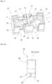
- FIG. 5 is a front view of the double-door module according to the invention without the cover of the control system;
- FIG. 6 is a front view of the double-door module according to the invention without the cover of the control system
- FIG. 7 is a bottom view of the double-door module according to the invention showing the locking recesses for the electromagnetic actuators associated with one of the doors of said module.
- FIG. 1 shows a seat unit 10 comprising two seats 11 , in which the seats 11 face one another.
- a seat 11 is adapted to switch between a ‘sitting’ position, corresponding to the position used in particular during the stop, take-off, and landing phases of the aircraft, and a ‘lying’ position, in which the seat 11 defines a substantially horizontal ‘lying’ surface for the passenger.
- the ‘seating’ position and the ‘lying’ position constitute configurations of the seat 11 in two extreme positions.
- the seat can also take intermediate positions, called relax positions, between these two extreme positions.
- a center console 12 positioned between the seats 11 comprises a transverse partition wall 14 .
- the partition wall preferably includes a space for mounting displays, electronic devices, storage compartments.
- the center console 12 comprises two foot zone 15 open in two opposite directions relative to one another. Each foot area is respectively associated with a corresponding seat 11 facing the opening of the foot zone 15 .
- a foot zone 15 is located in the extension of the corresponding seat 11 when the latter is in the lying position.
- the foot zones 15 are superposed at least partially along the longitudinal axis Y.
- the foot zones 15 are each delimited by a bottom 16 , the bottoms 16 being interconnected by a common wall 17 .
- the common wall 17 is advantageously inclined with respect to the longitudinal axis Y.
- each of the foot zones 15 also have a flat upper wall 18 , on which the passenger of the opposite seat 11 may in particular place objects.
- the upper wall 18 may thus be used as a table, working surface, dining table, cocktail table or any other suitable surface for a passenger seated in the opposite seat 11 (that is to say the seat 11 which has no access to the opening of the foot zone 15 ).
- a portion of the foot zone 15 extends into the space occupied by a passenger seated in the opposite seat 11 .
- the seat unit 10 In order to close the passage 20 of each seat 11 to an aircraft aisle, the seat unit 10 comprises a double-door module 23 at one side of the center console 12 .
- the first and second door 24 . 1 24 . 2 are superposed, in particular inside the housing 25 , when the doors 24 . 1 and 24 . 2 are simultaneously in the stored position.
- the two doors 24 . 1 , 24 . 2 are superposed along the majority of their surfaces in the stored position, or even over all of their surfaces. Under ‘the majority of their surfaces’ it is meant a superposition of the doors 24 . 1 , 24 . 2 along at least 50% of their surfaces, preferably along at least 80% of their surfaces.
- a straight line perpendicular to a surface of one of the doors 24 . 1 , 24 . 2 intersects the other door 24 . 1 , 24 . 2 .
- the passage from the stored position to the deployed position of the first door 24 . 1 is effected in a first direction D 1 opposite to a second direction D 2 along which the second door 24 . 2 moves from the stored position to a deployed position.
- the movements of the doors 24 . 1 , 24 . 2 are independent from one another.
- the casing 31 containing the control system 27 is distinct from the housing 25 containing the doors 24 . 1 and 24 . 2 , that is to say that the casing 31 contains only all the components of the control system 27 , so that the housing 25 does not contain any component of this control system 27 .
- the casing 31 of the control system 27 is arranged in the lower part of the module 23 .
- the casing 31 could alternatively be disposed in the upper part of the module 23 .
- the locking and unlocking device 28 comprises, for each door 24 . 1 , 24 . 2 , at least one electromagnetic actuator 33 . 1 , 33 . 2 , visible in FIG. 6 , intended to cooperate with a corresponding locking recess 34 . 1 , 34 . 2 in the door 24 . 1 , 24 . 2 and visible in FIG. 7 .
- the locking recess 34 . 1 , 34 . 2 is provided in the lower edge of the door.
- a first electromagnetic actuator 33 . 1 intended to be controlled by a passenger and a second electromagnetic actuator 33 . 2 intended to be controlled by a member of the staff.
- Locking recesses 34 . 1 , 34 . 2 respectively associated with the first actuator 33 . 1 and the second actuator 33 . 2 of a door, are visible in FIG. 7 .
- the actuators 33 . 1 , 33 . 2 and locking recesses 34 . 1 , 34 . 2 are arranged so that the corresponding door 24 . 1 , 24 . 2 can be blocked in the stored position.
- both recesses 34 . 1 , 34 . 2 have different geometries, preventing the electromagnet cooperating with the second locking recess 34 . 2 from being engaged in the first locking recess 34 . 1 .
- both recesses 34 . 1 , 34 . 2 and the corresponding actuator rods 33 . 1 , 33 . 2 will have for example different sizes and/or shapes.
- the displacement of a door 24 . 1 , 24 . 2 may be controlled by a corresponding actuating button 41 inside the seat module 11 .
- Sensors 42 are provided for transmitting information enabling a control unit 43 to manage the movement of the doors 24 . 1 , 24 . 2 according to an actuating or locking demand for the door from the passenger or the member of the staff.
- the seat units 10 allow the passengers to evacuate the seat, providing a clearance of the aisles in the aircraft.
- the invention can also be implemented with seats in other means of transport, such as bus, train, or boat seats.
Landscapes
- Engineering & Computer Science (AREA)
- Aviation & Aerospace Engineering (AREA)
- Lock And Its Accessories (AREA)
- Power-Operated Mechanisms For Wings (AREA)
Abstract
Description
-
- a first door movable in translation between a stored position and a deployed position,
- a second door movable in translation between a stored position and a deployed position,
- the first and second door being superposed when the first door and the second door are in the stored position, and
- a control system comprising a device for locking and unlocking the first door and/or the second door.
Claims (17)
Applications Claiming Priority (3)
| Application Number | Priority Date | Filing Date | Title |
|---|---|---|---|
| FR1870873A FR3084338B1 (en) | 2018-07-27 | 2018-07-27 | DOUBLE DOOR MODULE FOR AIRCRAFT SEATS |
| FR1870873 | 2018-07-27 | ||
| PCT/EP2019/068747 WO2020020658A1 (en) | 2018-07-27 | 2019-07-11 | Double-door module for airplane seats |
Publications (2)
| Publication Number | Publication Date |
|---|---|
| US20210163140A1 US20210163140A1 (en) | 2021-06-03 |
| US12030642B2 true US12030642B2 (en) | 2024-07-09 |
Family
ID=63896471
Family Applications (1)
| Application Number | Title | Priority Date | Filing Date |
|---|---|---|---|
| US17/263,472 Active 2041-03-06 US12030642B2 (en) | 2018-07-27 | 2019-07-11 | Double-door module for aircraft seats |
Country Status (5)
| Country | Link |
|---|---|
| US (1) | US12030642B2 (en) |
| EP (1) | EP3829976B1 (en) |
| CN (1) | CN112512922B (en) |
| FR (1) | FR3084338B1 (en) |
| WO (1) | WO2020020658A1 (en) |
Cited By (2)
| Publication number | Priority date | Publication date | Assignee | Title |
|---|---|---|---|---|
| US20230265687A1 (en) * | 2020-06-12 | 2023-08-24 | Recaro Aircraft Seating Gmbh & Co. Kg | Aircraft seat module |
| US20250108742A1 (en) * | 2023-10-03 | 2025-04-03 | Safran Seats Usa Llc | Armrest control mechanism for passenger seat |
Families Citing this family (5)
| Publication number | Priority date | Publication date | Assignee | Title |
|---|---|---|---|---|
| FR3095617B1 (en) * | 2019-04-30 | 2021-08-20 | Safran Seats | SET OF SEATS, ESPECIALLY FOR AN AIRCRAFT |
| GB2605994B (en) * | 2021-04-21 | 2024-02-07 | Thompson Aero Seating Ltd | Door assembly for passenger seating |
| FR3129917A1 (en) * | 2021-12-07 | 2023-06-09 | Safran Seats | Partition for aircraft seat arrangement with sliding door and associated aircraft seat arrangement. |
| FR3129918A1 (en) * | 2021-12-07 | 2023-06-09 | Safran Seats | Partition for aircraft seat arrangement with sliding door and associated aircraft seat arrangement. |
| GB2613629B (en) * | 2021-12-10 | 2026-01-07 | Safran Seats Gb Ltd | Aircraft interior unit with detachable panel |
Citations (9)
| Publication number | Priority date | Publication date | Assignee | Title |
|---|---|---|---|---|
| CN101426995A (en) | 2006-03-15 | 2009-05-06 | 克诺尔布莱姆斯轨道系统英国有限公司 | Platform screen door system |
| US20130241247A1 (en) * | 2012-03-14 | 2013-09-19 | B/E Aerospace, Inc. | Aircraft passenger suite with combination bed |
| WO2015155687A1 (en) | 2014-04-07 | 2015-10-15 | Zodiac Seats France | A seat unit |
| CN106029496A (en) | 2014-02-24 | 2016-10-12 | 空中客车德国运营有限责任公司 | Module for an aircraft cabin with a seat fastened to a door |
| WO2017066559A1 (en) | 2015-10-14 | 2017-04-20 | B/E Aerospace, Inc. | Aircraft passenger suite privacy screen control apparatus and method |
| EP3225548A1 (en) * | 2016-04-01 | 2017-10-04 | Thompson Aero Seating Limited | Passenger seating with multi-mode privacy door |
| FR3050717A1 (en) | 2016-04-29 | 2017-11-03 | Aircraft Interior Products - Aip | RETRACTABLE WINDOW FOR AIRCRAFT CAB |
| WO2018093825A1 (en) | 2016-11-15 | 2018-05-24 | Zodiac Seats Us Llc | Mini suite emergency egress solutions |
| US11174029B2 (en) * | 2020-03-06 | 2021-11-16 | Acumen Design Associates Ltd. | Outboard facing herringbone seating arrangement |
-
2018
- 2018-07-27 FR FR1870873A patent/FR3084338B1/en active Active
-
2019
- 2019-07-11 WO PCT/EP2019/068747 patent/WO2020020658A1/en not_active Ceased
- 2019-07-11 US US17/263,472 patent/US12030642B2/en active Active
- 2019-07-11 CN CN201980049849.9A patent/CN112512922B/en active Active
- 2019-07-11 EP EP19737125.5A patent/EP3829976B1/en active Active
Patent Citations (9)
| Publication number | Priority date | Publication date | Assignee | Title |
|---|---|---|---|---|
| CN101426995A (en) | 2006-03-15 | 2009-05-06 | 克诺尔布莱姆斯轨道系统英国有限公司 | Platform screen door system |
| US20130241247A1 (en) * | 2012-03-14 | 2013-09-19 | B/E Aerospace, Inc. | Aircraft passenger suite with combination bed |
| CN106029496A (en) | 2014-02-24 | 2016-10-12 | 空中客车德国运营有限责任公司 | Module for an aircraft cabin with a seat fastened to a door |
| WO2015155687A1 (en) | 2014-04-07 | 2015-10-15 | Zodiac Seats France | A seat unit |
| WO2017066559A1 (en) | 2015-10-14 | 2017-04-20 | B/E Aerospace, Inc. | Aircraft passenger suite privacy screen control apparatus and method |
| EP3225548A1 (en) * | 2016-04-01 | 2017-10-04 | Thompson Aero Seating Limited | Passenger seating with multi-mode privacy door |
| FR3050717A1 (en) | 2016-04-29 | 2017-11-03 | Aircraft Interior Products - Aip | RETRACTABLE WINDOW FOR AIRCRAFT CAB |
| WO2018093825A1 (en) | 2016-11-15 | 2018-05-24 | Zodiac Seats Us Llc | Mini suite emergency egress solutions |
| US11174029B2 (en) * | 2020-03-06 | 2021-11-16 | Acumen Design Associates Ltd. | Outboard facing herringbone seating arrangement |
Non-Patent Citations (2)
| Title |
|---|
| China Patent Application No. 201980049849.9, Office Action, dated Apr. 21, 2023. |
| International Patent Application No. PCT/EP2019/068747, International Search Report (with English translation) and Written Opinion, dated Sep. 16, 2019. |
Cited By (4)
| Publication number | Priority date | Publication date | Assignee | Title |
|---|---|---|---|---|
| US20230265687A1 (en) * | 2020-06-12 | 2023-08-24 | Recaro Aircraft Seating Gmbh & Co. Kg | Aircraft seat module |
| US12559993B2 (en) * | 2020-06-12 | 2026-02-24 | Recaro Aircraft Seating Gmbh & Co. Kg | Aircraft seat module |
| US20250108742A1 (en) * | 2023-10-03 | 2025-04-03 | Safran Seats Usa Llc | Armrest control mechanism for passenger seat |
| US12403804B2 (en) * | 2023-10-03 | 2025-09-02 | Safran Seats Usa Llc | Armrest control mechanism for passenger seat |
Also Published As
| Publication number | Publication date |
|---|---|
| CN112512922B (en) | 2023-11-17 |
| EP3829976B1 (en) | 2025-10-01 |
| FR3084338B1 (en) | 2021-02-12 |
| US20210163140A1 (en) | 2021-06-03 |
| EP3829976A1 (en) | 2021-06-09 |
| CN112512922A (en) | 2021-03-16 |
| WO2020020658A1 (en) | 2020-01-30 |
| FR3084338A1 (en) | 2020-01-31 |
Similar Documents
| Publication | Publication Date | Title |
|---|---|---|
| US12030642B2 (en) | Double-door module for aircraft seats | |
| US11919643B2 (en) | Self-deploying counter for multimode transformable monuments | |
| US20210171202A1 (en) | Device for closing a passage between two seat units | |
| CN105923164B (en) | Washing chamber device for the vehicles | |
| EP3129281B1 (en) | Retaining system for a door element and method for locking and releasing a door element on board of an aircraft | |
| US7517014B2 (en) | Passenger seat with luggage compartment | |
| ES2236437T3 (en) | RETRACTABLE CABINET. | |
| US20190210733A1 (en) | Seat arrangement, in particular for an airplane | |
| JP4879262B2 (en) | Long-range aircraft | |
| CA2940262C (en) | Module for an aircraft cabin with a seat fastened to a door | |
| CN107949520B (en) | Cabin layout with optimized passenger and crew service areas | |
| US20220332425A1 (en) | Aircraft passenger seat unit and associated cabin arrangement | |
| US11999486B2 (en) | Device for closing a passage between two seat units | |
| US11780585B2 (en) | Passenger seat arrangement | |
| JP2004017673A (en) | Baggage storage bin of airplane | |
| EP3741676B1 (en) | Multimode transformable monument | |
| US12344380B2 (en) | Aircraft cabin | |
| EP4079639B1 (en) | Deployable cabin attendant seat system | |
| US12409938B2 (en) | Seat arrangements, in particular for an aircraft cabin | |
| ES2799948T3 (en) | Passenger cabin with sliding wardrobe | |
| US11975843B2 (en) | Seat assembly, in particular for an aircraft | |
| US20250115359A1 (en) | Redundant rail cover assembly with failure indicators | |
| EP4506251A1 (en) | Seat extension furniture for aircraft seats | |
| US20250223042A1 (en) | Aircraft passenger seat unit and associated cabin arrangement | |
| EP4303126A1 (en) | Dual purpose legrest for a multiple passenger side facing aircraft seat |
Legal Events
| Date | Code | Title | Description |
|---|---|---|---|
| FEPP | Fee payment procedure |
Free format text: ENTITY STATUS SET TO UNDISCOUNTED (ORIGINAL EVENT CODE: BIG.); ENTITY STATUS OF PATENT OWNER: LARGE ENTITY |
|
| STPP | Information on status: patent application and granting procedure in general |
Free format text: APPLICATION DISPATCHED FROM PREEXAM, NOT YET DOCKETED |
|
| AS | Assignment |
Owner name: SAFRAN SEATS, FRANCE Free format text: ASSIGNMENT OF ASSIGNORS INTEREST;ASSIGNORS:JASNY, FRANCK;GUERRA, DANIELE;LAVERGNE, DENYS;AND OTHERS;REEL/FRAME:057151/0657 Effective date: 20180727 |
|
| STPP | Information on status: patent application and granting procedure in general |
Free format text: DOCKETED NEW CASE - READY FOR EXAMINATION |
|
| STPP | Information on status: patent application and granting procedure in general |
Free format text: NON FINAL ACTION MAILED |
|
| STPP | Information on status: patent application and granting procedure in general |
Free format text: RESPONSE TO NON-FINAL OFFICE ACTION ENTERED AND FORWARDED TO EXAMINER |
|
| STPP | Information on status: patent application and granting procedure in general |
Free format text: FINAL REJECTION MAILED |
|
| STPP | Information on status: patent application and granting procedure in general |
Free format text: ADVISORY ACTION MAILED |
|
| STPP | Information on status: patent application and granting procedure in general |
Free format text: DOCKETED NEW CASE - READY FOR EXAMINATION |
|
| STPP | Information on status: patent application and granting procedure in general |
Free format text: NOTICE OF ALLOWANCE MAILED -- APPLICATION RECEIVED IN OFFICE OF PUBLICATIONS |
|
| STPP | Information on status: patent application and granting procedure in general |
Free format text: PUBLICATIONS -- ISSUE FEE PAYMENT VERIFIED |
|
| STCF | Information on status: patent grant |
Free format text: PATENTED CASE |