US12028046B2 - Bulk acoustic wave resonator filters including a high impedance shunt branch and methods of forming the same - Google Patents
Bulk acoustic wave resonator filters including a high impedance shunt branch and methods of forming the same Download PDFInfo
- Publication number
- US12028046B2 US12028046B2 US17/323,332 US202117323332A US12028046B2 US 12028046 B2 US12028046 B2 US 12028046B2 US 202117323332 A US202117323332 A US 202117323332A US 12028046 B2 US12028046 B2 US 12028046B2
- Authority
- US
- United States
- Prior art keywords
- baw
- impedance
- pass
- shunt
- electrode
- Prior art date
- Legal status (The legal status is an assumption and is not a legal conclusion. Google has not performed a legal analysis and makes no representation as to the accuracy of the status listed.)
- Active, expires
Links
Images


Classifications
-
- H—ELECTRICITY
- H03—ELECTRONIC CIRCUITRY
- H03H—IMPEDANCE NETWORKS, e.g. RESONANT CIRCUITS; RESONATORS
- H03H9/00—Networks comprising electromechanical or electro-acoustic elements; Electromechanical resonators
- H03H9/15—Constructional features of resonators consisting of piezoelectric or electrostrictive material
- H03H9/205—Constructional features of resonators consisting of piezoelectric or electrostrictive material having multiple resonators
-
- H—ELECTRICITY
- H03—ELECTRONIC CIRCUITRY
- H03H—IMPEDANCE NETWORKS, e.g. RESONANT CIRCUITS; RESONATORS
- H03H3/00—Apparatus or processes specially adapted for the manufacture of impedance networks, resonating circuits, resonators
- H03H3/007—Apparatus or processes specially adapted for the manufacture of impedance networks, resonating circuits, resonators for the manufacture of electromechanical resonators or networks
- H03H3/02—Apparatus or processes specially adapted for the manufacture of impedance networks, resonating circuits, resonators for the manufacture of electromechanical resonators or networks for the manufacture of piezoelectric or electrostrictive resonators or networks
-
- H—ELECTRICITY
- H03—ELECTRONIC CIRCUITRY
- H03H—IMPEDANCE NETWORKS, e.g. RESONANT CIRCUITS; RESONATORS
- H03H9/00—Networks comprising electromechanical or electro-acoustic elements; Electromechanical resonators
- H03H9/46—Filters
- H03H9/54—Filters comprising resonators of piezoelectric or electrostrictive material
- H03H9/56—Monolithic crystal filters
- H03H9/566—Electric coupling means therefor
- H03H9/568—Electric coupling means therefor consisting of a ladder configuration
-
- H—ELECTRICITY
- H03—ELECTRONIC CIRCUITRY
- H03H—IMPEDANCE NETWORKS, e.g. RESONANT CIRCUITS; RESONATORS
- H03H9/00—Networks comprising electromechanical or electro-acoustic elements; Electromechanical resonators
- H03H9/46—Filters
- H03H9/54—Filters comprising resonators of piezoelectric or electrostrictive material
- H03H9/58—Multiple crystal filters
- H03H9/60—Electric coupling means therefor
- H03H9/605—Electric coupling means therefor consisting of a ladder configuration
-
- H—ELECTRICITY
- H03—ELECTRONIC CIRCUITRY
- H03H—IMPEDANCE NETWORKS, e.g. RESONANT CIRCUITS; RESONATORS
- H03H3/00—Apparatus or processes specially adapted for the manufacture of impedance networks, resonating circuits, resonators
- H03H3/007—Apparatus or processes specially adapted for the manufacture of impedance networks, resonating circuits, resonators for the manufacture of electromechanical resonators or networks
- H03H3/02—Apparatus or processes specially adapted for the manufacture of impedance networks, resonating circuits, resonators for the manufacture of electromechanical resonators or networks for the manufacture of piezoelectric or electrostrictive resonators or networks
- H03H2003/023—Apparatus or processes specially adapted for the manufacture of impedance networks, resonating circuits, resonators for the manufacture of electromechanical resonators or networks for the manufacture of piezoelectric or electrostrictive resonators or networks the resonators or networks being of the membrane type
-
- H—ELECTRICITY
- H03—ELECTRONIC CIRCUITRY
- H03H—IMPEDANCE NETWORKS, e.g. RESONANT CIRCUITS; RESONATORS
- H03H3/00—Apparatus or processes specially adapted for the manufacture of impedance networks, resonating circuits, resonators
- H03H3/007—Apparatus or processes specially adapted for the manufacture of impedance networks, resonating circuits, resonators for the manufacture of electromechanical resonators or networks
- H03H3/02—Apparatus or processes specially adapted for the manufacture of impedance networks, resonating circuits, resonators for the manufacture of electromechanical resonators or networks for the manufacture of piezoelectric or electrostrictive resonators or networks
- H03H2003/025—Apparatus or processes specially adapted for the manufacture of impedance networks, resonating circuits, resonators for the manufacture of electromechanical resonators or networks for the manufacture of piezoelectric or electrostrictive resonators or networks the resonators or networks comprising an acoustic mirror
Definitions
- BAWR Bulk acoustic wave resonators
- BAW bulk acoustic wave
- a high-impedance shunt branch can include a plurality of high-impedance BAW shunt resonators coupled together in-series to provide an impedance for the high-impedance shunt branch that is greater the other shunt branches in the BAW resonator ladder topology pass-band filter.
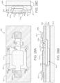
- FIG. 1 A is a simplified diagram illustrating an acoustic resonator device having topside interconnections according to an example of the present invention.
- FIG. 1 B is a simplified diagram illustrating an acoustic resonator device having bottom-side interconnections according to an example of the present invention.
- FIG. 1 D is a simplified diagram illustrating an acoustic resonator device having interposer/cap-free structure interconnections with a shared backside trench according to an example of the present invention.
- FIGS. 2 and 3 are simplified diagrams illustrating steps for a method of manufacture for an acoustic resonator device according to an example of the present invention.
- FIG. 4 A is a simplified diagram illustrating a step for a method creating a topside micro-trench according to an example of the present invention.
- FIGS. 4 D and 4 E are simplified diagrams illustrating an alternative method for conducting the method step of forming a topside micro-trench as described in FIG. 4 A .
- FIGS. 5 to 8 are simplified diagrams illustrating steps for a method of manufacture for an acoustic resonator device according to an example of the present invention.
- FIG. 13 is a simplified diagram illustrating a step for a method of manufacture for an acoustic resonator device according to an example of the present invention.
- FIGS. 14 A to 14 G are simplified diagrams illustrating method steps for a cap wafer process for an acoustic resonator device according to an example of the present invention.
- FIGS. 15 A- 15 E are simplified diagrams illustrating method steps for making an acoustic resonator device with shared backside trench, which can be implemented in both interposer/cap and interposer free versions, according to examples of the present invention.
- FIGS. 32 A- 32 C through FIGS. 46 A- 46 C are simplified diagrams illustrating various cross-sectional views of a single crystal acoustic resonator device and of method steps for a cavity bond transfer process for single crystal acoustic resonator devices according to an example of the present invention.
- FIG. 62 is a simplified diagram illustrating application areas for 5.2 GHz RF filters in Tri-Band Wi-Fi radios according to examples of the present invention.
- FIGS. 63 A- 63 C are simplified diagrams illustrating cross-sectional views of resonator devices according to various examples of the present invention.
- FIG. 65 is a simplified diagram illustrating a packing approach according to an example of the present invention.
- FIG. 67 is a schematic diagram illustrating a BAW resonator ladder topology pass-band filter including a high-impedance shunt branch including series coupled high-impedance shunt resonators located between an output and an input of the filter in some embodiments according to the invention.
- FIG. 68 is a schematic diagram illustrating a BAW resonator ladder topology pass-band filter including a high-impedance shunt branch including series coupled high-impedance shunt resonators located at an input of the filter in some embodiments according to the invention.
- FIG. 69 is a schematic diagram illustrating a BAW resonator ladder topology pass-band filter including a plurality of BAW resonators included in each of the series branches and a high-impedance shunt branch that includes four high-impedance shunt resonators coupled in series located at an output of the filter in some embodiments according to the invention.
- FIG. 70 is a graph illustrating the response of the BAW resonator ladder topology pass-band filter of FIG. 69 overlaid with a curve showing the resonance frequency f s of the high-impedance shunt branch in some embodiments according to the invention.
- the present invention provides techniques related to a method of manufacture and structure for bulk acoustic wave resonator devices, single crystal resonator devices, single crystal filter and resonator devices, and the like.
- the invention has been applied to a single crystal resonator device for a communication device, mobile device, computing device, among others.
- a ladder topology pass-band filter can be implemented to provide a high Qs (Q series) shunt resonator branch by providing multiple series coupled high-impedance BAW resonators in a high-impedance shunt branch of the ladder topology pass-band filter.
- the high-impedance shunt resonator branch can provide high Qs, which can improve the steepness on the lower edge of the filter.
- implementing the high-impedance shunt resonator branch with a series configuration of high-impedance BAW resonators (rather than a single high-impedance resonator) can provide high Qs and adequate coupling. In some embodiments, this can be realized using high-impedance resonators (e.g., 80/100/2000) in several combinations such as 5/4/2 resonators each in series.
- FIG. 66 is a schematic diagram illustrating a (Bulk Acoustic Wave) BAW resonator ladder topology pass-band filter including a high-impedance shunt branch with series coupled high-impedance shunt resonators located at an output of the filter in some embodiments according to the invention.
- the high-impedance shunt branch includes a plurality of BAW high-impedance resonators coupled in series with one another in some embodiments.
- the high-impedance shunt branch has a combined impedance that is greater than that of the other shunt branches in the ladder.
- the combined impedance of the series arrangement of the BAW high-impedance resonators can be about 400 ohms. Other impedance values may also be provided in some embodiments according to the invention.
- each of the BAW high-impedance shunt resonators included in series arrangement of the high-impedance shunt branch is at least about twice the impedance of the other BAW resonators (i.e., BAW resonators included in the series branches and BAW resonators included in the other shunt branches of the ladder).
- the high-impedance shunt branch can be located at the output of the ladder to provide improved 2 nd harmonic rejection in some embodiments according to the invention.
- a resonance frequency peak that is generated by the high-impedance shunt branch can be greater than the respective resonance frequency peaks generated by the other shunt branches in the BAW resonator ladder topology pass-band filter.
- FIG. 70 is a graph illustrating the response of a BAW resonator ladder topology pass-band filter with a high-impedance shunt branch having series coupled high-impedance BAW shunt resonators. According to FIG.
- the response of a BAW resonator ladder topology pass-band filter is overlaid with a curve showing the resonance frequency (f s ) peak of the high-impedance shunt branch that is greater than the respective resonance frequency (f s ) peaks generated by the other BAW shunt resonator branches in the ladder in some embodiments according to the invention.
- the frequency of the resonance frequency (f s ) peak of the high-impedance shunt branch is aligned with the lower edge of the pass-band of frequencies and creates a null in the filter response that is adjacent to and below the lower edge of the pass-band of frequencies.
- FIG. 67 is a schematic diagram illustrating a BAW resonator ladder topology pass-band filter including a high-impedance shunt branch including series coupled high-impedance shunt resonators located between an output and an input of the filter in some embodiments according to the invention.
- the high-impedance shunt branch includes a plurality of BAW high-impedance resonators coupled in series with one another in some embodiments.
- the high-impedance shunt branch of FIG. 67 has a combined impedance that is greater than that of the other shunt branches in the ladder.
- the combined impedance of the series arrangement of the BAW high-impedance resonators can be about 400 ohms. Other impedance values may also be provided in some embodiments according to the invention.
- each of the BAW high-impedance shunt resonators included in series arrangement of the high-impedance shunt branch can be at least about twice the impedance of the other BAW resonators (i.e., BAW resonators included in the series branches and BAW resonators included in the other shunt branches of the ladder).
- the high-impedance shunt branch can be located between the output and the input of the filter to provide greater flexibility in layout for the BAW resonator ladder topology pass-band filter, in some embodiments according to the invention.
- a resonance frequency peak that is generated by the high-impedance shunt branch in FIG. 67 can be greater than the respective resonance frequency peaks generated by the other shunt branches in the BAW resonator ladder topology pass-band filter as shown in FIG. 70 .
- each of the BAW high-impedance shunt resonators included in series arrangement of the high-impedance shunt branch can be at least about twice the impedance of the other BAW resonators (i.e., BAW resonators included in the series branches and BAW resonators included in the other shunt branches of the ladder).
- the high-impedance shunt branch can be located at the input of the filter to provide increased power handling in some embodiments according to the invention.
- a resonance frequency peak that is generated by the high-impedance shunt branch in FIG. 68 can be greater than the respective resonance frequency peaks generated by the other shunt branches in the BAW resonator ladder topology pass-band filter as shown in FIG. 70 .
- FIG. 69 is a schematic diagram illustrating a BAW resonator ladder topology pass-band filter including a plurality of BAW resonators included in each of the series branches and a high-impedance shunt branch that includes four high-impedance shunt resonators coupled in series located at an output of the filter in some embodiments according to the invention.
- the four BAW high-impedance resonators coupled in series with one another can provide a combined impedance of about 400 ohms wherein each of the four BAW high-impedance resonators has an impedance of about 100 ohms in some embodiments.
- Other impedance values may also be provided in some embodiments according to the invention.
- the high-impedance shunt branch of FIG. 69 has a combined impedance that is greater than that of the other shunt branches in the ladder. Accordingly, the size (i.e., surface area) of the BAW resonators in the high-impedance shunt branch can be less than the size of the other BAW resonators in the ladder.
- each of the BAW high-impedance shunt resonators included in series arrangement of the high-impedance shunt branch can be at least about twice the impedance of the other BAW resonators (i.e., BAW resonators included in the series branches and BAW resonators included in the other shunt branches of the ladder).
- a resonance frequency peak that is generated by the high-impedance shunt branch in FIG. 69 can be greater than the respective resonance frequency peaks generated by the other shunt branches in the BAW resonator ladder topology pass-band filter as shown in FIG. 70 .
- each BAW resonator may be formed according to a particular pattern to provide a corresponding surface area, which may correspond to an impedance of the particular BAW resonator. Accordingly, particular ones of the BAW resonators may be formed different from one another or the same, depending on the particular filter specification.
- FIG. 1 A is a simplified diagram illustrating an acoustic resonator device 101 having topside interconnections according to an example of the present invention.
- device 101 includes a thinned seed substrate 112 with an overlying single crystal piezoelectric layer 120 , which has a micro-via 129 .
- the micro-via 129 can include a topside micro-trench 121 , a topside metal plug 146 , a backside trench 114 , and a backside metal plug 147 .
- device 101 is depicted with a single micro-via 129 , device 101 may have multiple micro-vias.
- a topside metal electrode 130 is formed overlying the piezoelectric layer 120 .
- the thinned substrate 112 has the first and second backside trenches 113 , 114 .
- a backside metal electrode 131 is formed underlying a portion of the thinned seed substrate 112 , the first backside trench 113 , and the topside metal electrode 130 .
- the backside metal plug 147 is formed underlying a portion of the thinned seed substrate 112 , the second backside trench 114 , and the topside metal 145 . This backside metal plug 147 is electrically coupled to the topside metal plug 146 and the backside metal electrode 131 .
- a backside cap structure 161 is bonded to the thinned seed substrate 112 , underlying the first and second backside trenches 113 , 114 . Further details relating to the method of manufacture of this device will be discussed starting from FIG. 2 .
- FIG. 1 B is a simplified diagram illustrating an acoustic resonator device 102 having backside interconnections according to an example of the present invention.
- device 101 includes a thinned seed substrate 112 with an overlying piezoelectric layer 120 , which has a micro-via 129 .
- the micro-via 129 can include a topside micro-trench 121 , a topside metal plug 146 , a backside trench 114 , and a backside metal plug 147 .
- device 102 is depicted with a single micro-via 129 , device 102 may have multiple micro-vias.
- a topside metal electrode 130 is formed overlying the piezoelectric layer 120 .
- a top cap structure is bonded to the piezoelectric layer 120 .
- This top cap structure 119 includes bond pads which are connected to one or more bond pads 144 and topside metal 145 on piezoelectric layer 120 .
- the topside metal 145 includes a topside metal plug 146 .
- the thinned substrate 112 has the first and second backside trenches 113 , 114 .
- a backside metal electrode 131 is formed underlying a portion of the thinned seed substrate 112 , the first backside trench 113 , and the topside metal electrode 130 .
- a backside metal plug 147 is formed underlying a portion of the thinned seed substrate 112 , the second backside trench 114 , and the topside metal plug 146 . This backside metal plug 147 is electrically coupled to the topside metal plug 146 .
- a backside cap structure 162 is bonded to the thinned seed substrate 112 , underlying the first and second backside trenches.
- the thinned substrate 112 has the first and second backside trenches 113 , 114 .
- a backside metal electrode 131 is formed underlying a portion of the thinned seed substrate 112 , the first backside trench 113 , and the topside metal electrode 130 .
- a backside metal plug 147 is formed underlying a portion of the thinned seed substrate 112 , the second backside trench 114 , and the topside metal 145 . This backside metal plug 147 is electrically coupled to the topside metal plug 146 and the backside metal electrode 131 . Further details relating to the method of manufacture of this device will be discussed starting from FIG. 2 .
- the thinned substrate 112 has a first backside trench 113 .
- a backside metal electrode 131 is formed underlying a portion of the thinned seed substrate 112 , the first backside trench 113 , and the topside metal electrode 130 .
- a backside metal 147 is formed underlying a portion of the thinned seed substrate 112 , the second backside trench 114 , and the topside metal 145 . This backside metal 147 is electrically coupled to the topside metal plug 146 and the backside metal electrode 131 . Further details relating to the method of manufacture of this device will be discussed starting from FIG. 2 .
- FIGS. 2 and 3 are simplified diagrams illustrating steps for a method of manufacture for an acoustic resonator device according to an example of the present invention. This method illustrates the process for fabricating an acoustic resonator device similar to that shown in FIG. 1 A .
- FIG. 2 can represent a method step of providing a partially processed piezoelectric substrate.
- device 102 includes a seed substrate 110 with a piezoelectric layer 120 formed overlying.
- the seed substrate can include silicon, silicon carbide, aluminum oxide, or single crystal aluminum gallium nitride materials, or the like.
- the piezoelectric layer 120 can include a piezoelectric single crystal layer or a thin film piezoelectric single crystal layer.
- FIG. 3 can represent a method step of forming a top side metallization or top resonator metal electrode 130 .
- the topside metal electrode 130 can include a molybdenum, aluminum, ruthenium, or titanium material, or the like and combinations thereof.
- This layer can be deposited and patterned on top of the piezoelectric layer by a lift-off process, a wet etching process, a dry etching process, a metal printing process, a metal laminating process, or the like.
- the lift-off process can include a sequential process of lithographic patterning, metal deposition, and lift-off steps to produce the topside metal layer.
- the wet/dry etching processes can includes sequential processes of metal deposition, lithographic patterning, metal deposition, and metal etching steps to produce the topside metal layer.
- FIG. 4 A is a simplified diagram illustrating a step for a method of manufacture for an acoustic resonator device 401 according to an example of the present invention.
- This figure can represent a method step of forming one or more topside micro-trenches 121 within a portion of the piezoelectric layer 120 .
- This topside micro-trench 121 can serve as the main interconnect junction between the top and bottom sides of the acoustic membrane, which will be developed in later method steps.
- the topside micro-trench 121 is extends all the way through the piezoelectric layer 120 and stops in the seed substrate 110 .
- This topside micro-trench 121 can be formed through a dry etching process, a laser drilling process, or the like.
- FIGS. 4 B and 4 C describe these options in more detail.
- FIGS. 4 B and 4 C are simplified diagrams illustrating alternative methods for conducting the method step as described in FIG. 4 A .
- FIG. 4 B represents a method step of using a laser drill, which can quickly and accurately form the topside micro-trench 121 in the piezoelectric layer 120 .
- the laser drill can be used to form nominal 50 um holes, or holes between 10 um and 500 um in diameter, through the piezoelectric layer 120 and stop in the seed substrate 110 below the interface between layers 120 and 110 .
- a protective layer 122 can be formed overlying the piezoelectric layer 120 and the topside metal electrode 130 . This protective layer 122 can serve to protect the device from laser debris and to provide a mask for the etching of the topside micro-via 121 .
- the laser drill can be an 11 W high power diode-pumped UV laser, or the like.
- This mask 122 can be subsequently removed before proceeding to other steps.
- the mask may also be omitted from the laser drilling process, and air flow can be used to remove laser debris.
- FIG. 4 C can represent a method step of using a dry etching process to form the topside micro-trench 121 in the piezoelectric layer 120 .
- a lithographic masking layer 123 can be forming overlying the piezoelectric layer 120 and the topside metal electrode 130 .
- the topside micro-trench 121 can be formed by exposure to plasma, or the like.
- FIGS. 12 A to 12 E are simplified diagrams illustrating steps for a method of manufacture for an acoustic resonator device according to an example of the present invention. More specifically, these figures describe additional steps for processing the blind via interposer “ 602 ” version of the top cap structure.
- FIG. 12 A shows an acoustic resonator device 1201 with blind vias 152 in the top cap structure.
- the interposer substrate 119 is thinned, which forms a thinned interposer substrate 118 , to expose the blind vias 152 .
- This thinning process can be a combination of a grinding process and etching process as described for the thinning of the seed substrate.
- FIG. 12 A shows an acoustic resonator device 1201 with blind vias 152 in the top cap structure.
- the interposer substrate 119 is thinned, which forms a thinned interposer substrate 118 , to expose the blind vias 152 .
- a redistribution layer (RDL) process and metallization process can be applied to create top cap bond pads 160 that are formed overlying the blind vias 152 and are electrically coupled to the blind vias 152 .
- RDL redistribution layer
- metallization metallization process
- FIG. 12 D a ball grid array (BGA) process can be applied to form solder balls 170 overlying and electrically coupled to the top cap bond pads 160 . This process leaves the acoustic resonator device ready for wire bonding 171 , as shown in FIG. 12 E .
- these backside metals 131 , 147 can either be deposited and patterned on the surface of the piezoelectric layer 120 or rerouted to the backside of the substrate 112 .
- the backside metal electrode may be patterned such that it is configured within the boundaries of the shared backside trench such that the backside metal electrode does not come in contact with one or more side-walls of the seed substrate created during the forming of the shared backside trench.
- FIG. 15 E can represent a method step of bonding a backside cap structure 162 , similar to that described in FIGS. 11 A and 11 B , following a de-bonding of the temporary carrier 218 and cleaning of the topside of the device to remove the temporary adhesive 217 .
- FIGS. 11 A and 11 B can represent a method step of bonding a backside cap structure 162 , similar to that described in FIGS. 11 A and 11 B , following a de-bonding of the temporary carrier 218 and cleaning of the topside of the device to remove the temporary adhesive 217 .
- the present device can be manufactured in a relatively simple and cost effective manner while using conventional materials and/or methods according to one of ordinary skill in the art.
- Using the present method one can create a reliable single crystal based acoustic resonator using multiple ways of three-dimensional stacking through a wafer level process.
- Such filters or resonators can be implemented in an RF filter device, an RF filter system, or the like.
- one or more of these benefits may be achieved.
- Single crystalline or epitaxial piezoelectric thin films grown on compatible crystalline substrates exhibit good crystalline quality and high piezoelectric performance even down to very thin thicknesses, e.g., 0.4 um.
- the present invention provides manufacturing processes and structures for high quality bulk acoustic wave resonators with single crystalline or epitaxial piezoelectric thin films for high frequency BAW filter applications.
- FIGS. 19 A- 19 C are simplified diagrams illustrating various cross-sectional views of a single crystal acoustic resonator device and of method steps for a transfer process using a sacrificial layer for single crystal acoustic resonator devices according to an example of the present invention. As shown, these figures illustrate the method step of forming a sacrificial layer 1910 overlying a portion of the first electrode 1810 and a portion of the piezoelectric film 1620 .
- the sacrificial layer 1910 can include polycrystalline silicon (poly-Si), amorphous silicon (a-Si), or other like materials.
- FIGS. 20 A- 20 C are simplified diagrams illustrating various cross-sectional views of a single crystal acoustic resonator device and of method steps for a transfer process using a sacrificial layer for single crystal acoustic resonator devices according to an example of the present invention.
- these figures illustrate the method step of forming a support layer 2010 overlying the sacrificial layer 1910 , the first electrode 1710 , and the piezoelectric film 1620 .
- the support layer 2010 can include silicon dioxide (SiO.sub.2), silicon nitride (SiN), or other like materials.
- this support layer 2010 can be deposited with a thickness of about 2-3 um.
- other support layers e.g., SiNx
- FIGS. 21 A- 21 C are simplified diagrams illustrating various cross-sectional views of a single crystal acoustic resonator device and of method steps for a transfer process using a sacrificial layer for single crystal acoustic resonator devices according to an example of the present invention. As shown, these figures illustrate the method step of polishing the support layer 2010 to form a polished support layer 2011 .
- the polishing process can include a chemical-mechanical planarization process or the like.
- FIGS. 22 A- 22 C are simplified diagrams illustrating various cross-sectional views of a single crystal acoustic resonator device and of method steps for a transfer process using a sacrificial layer for single crystal acoustic resonator devices according to an example of the present invention. As shown, these figures illustrate flipping the device and physically coupling overlying the support layer 2011 overlying a bond substrate 2210 .
- the bond substrate 2210 can include a bonding support layer 2220 (SiO.sub.2 or like material) overlying a substrate having silicon (Si), sapphire (Al.sub.2O.sub.3), silicon dioxide (SiO.sub.2), silicon carbide (SiC), or other like materials.
- the bonding support layer 2220 of the bond substrate 2210 is physically coupled to the polished support layer 2011 .
- the physical coupling process can include a room temperature bonding process following by a 300 degree Celsius annealing process.
- FIGS. 23 A- 23 C are simplified diagrams illustrating various cross-sectional views of a single crystal acoustic resonator device and of method steps for a transfer process using a sacrificial layer for single crystal acoustic resonator devices according to an example of the present invention. As shown, these figures illustrate the method step of removing the growth substrate 1610 or otherwise the transfer of the piezoelectric film 1620 .
- the removal process can include a grinding process, a blanket etching process, a film transfer process, an ion implantation transfer process, a laser crack transfer process, or the like and combinations thereof.
- FIGS. 24 A- 24 C are simplified diagrams illustrating various cross-sectional views of a single crystal acoustic resonator device and of method steps for a transfer process using a sacrificial layer for single crystal acoustic resonator devices according to an example of the present invention. As shown, these figures illustrate the method step of forming an electrode contact via 2410 within the piezoelectric film 1620 (becoming piezoelectric film 1621 ) overlying the first electrode 1710 and forming one or more release holes 2420 within the piezoelectric film 1620 and the first passivation layer 1810 overlying the sacrificial layer 1910 .
- the via forming processes can include various types of etching processes.
- FIGS. 25 A- 25 C are simplified diagrams illustrating various cross-sectional views of a single crystal acoustic resonator device and of method steps for a transfer process using a sacrificial layer for single crystal acoustic resonator devices according to an example of the present invention.
- these figures illustrate the method step of forming a second electrode 2510 overlying the piezoelectric film 1621 .
- the formation of the second electrode 2510 includes depositing molybdenum (Mo), ruthenium (Ru), tungsten (W), or other like materials; and then etching the second electrode 2510 to form an electrode cavity 2511 and to remove portion 2511 from the second electrode to form a top metal 2520 .
- the top metal 2520 is physically coupled to the first electrode 1720 through electrode contact via 2410 .
- FIGS. 26 A- 26 C are simplified diagrams illustrating various cross-sectional views of a single crystal acoustic resonator device and of method steps for a transfer process using a sacrificial layer for single crystal acoustic resonator devices according to an example of the present invention. As shown, these figures illustrate the method step of forming a first contact metal 2610 overlying a portion of the second electrode 2510 and a portion of the piezoelectric film 1621 , and forming a second contact metal 2611 overlying a portion of the top metal 2520 and a portion of the piezoelectric film 1621 .
- the first and second contact metals can include gold (Au), aluminum (Al), copper (Cu), nickel (Ni), aluminum bronze (AlCu), or related alloys of these materials or other like materials.
- FIGS. 27 A- 27 C are simplified diagrams illustrating various cross-sectional views of a single crystal acoustic resonator device and of method steps for a transfer process using a sacrificial layer for single crystal acoustic resonator devices according to an example of the present invention. As shown, these figures illustrate the method step of forming a second passivation layer 2710 overlying the second electrode 2510 , the top metal 2520 , and the piezoelectric film 1621 .
- the second passivation layer 2710 can include silicon nitride (SiN), silicon oxide (SiOx), or other like materials.
- the second passivation layer 2710 can have a thickness ranging from about 50 nm to about 100 nm.
- FIGS. 28 A- 28 C are simplified diagrams illustrating various cross-sectional views of a single crystal acoustic resonator device and of method steps for a transfer process using a sacrificial layer for single crystal acoustic resonator devices according to an example of the present invention. As shown, these figures illustrate the method step of removing the sacrificial layer 1910 to form an air cavity 2810 .
- the removal process can include a poly-Si etch or an a-Si etch, or the like.
- FIGS. 29 A- 29 C are simplified diagrams illustrating various cross-sectional views of a single crystal acoustic resonator device and of method steps for a transfer process using a sacrificial layer for single crystal acoustic resonator devices according to another example of the present invention. As shown, these figures illustrate the method step of processing the second electrode 2510 and the top metal 2520 to form a processed second electrode 2910 and a processed top metal 2920 . This step can follow the formation of second electrode 2510 and top metal 2520 .
- the processing of these two components includes depositing molybdenum (Mo), ruthenium (Ru), tungsten (W), or other like materials; and then etching (e.g., dry etch or the like) this material to form the processed second electrode 2910 with an electrode cavity 2912 and the processed top metal 2920 .
- the processed top metal 2920 remains separated from the processed second electrode 2910 by the removal of portion 2911 .
- the processed second electrode 2910 is characterized by the addition of an energy confinement structure configured on the processed second electrode 2910 to increase Q.
- FIGS. 30 A- 30 C are simplified diagrams illustrating various cross-sectional views of a single crystal acoustic resonator device and of method steps for a transfer process using a sacrificial layer for single crystal acoustic resonator devices according to another example of the present invention. As shown, these figures illustrate the method step of processing the first electrode 1710 to form a processed first electrode 2310 . This step can follow the formation of first electrode 1710 .
- the processing of these two components includes depositing molybdenum (Mo), ruthenium (Ru), tungsten (W), or other like materials; and then etching (e.g., dry etch or the like) this material to form the processed first electrode 3010 with an electrode cavity, similar to the processed second electrode 2910 .
- Air cavity 2811 shows the change in cavity shape due to the processed first electrode 3010 .
- the processed first electrode 3010 is characterized by the addition of an energy confinement structure configured on the processed second electrode 3010 to increase Q.
- FIGS. 31 A- 31 C are simplified diagrams illustrating various cross-sectional views of a single crystal acoustic resonator device and of method steps for a transfer process using a sacrificial layer for single crystal acoustic resonator devices according to another example of the present invention. As shown, these figures illustrate the method step of processing the first electrode 1710 , to form a processed first electrode 2310 , and the second electrode 2510 /top metal 2520 to form a processed second electrode 2910 /processed top metal 2920 . These steps can follow the formation of each respective electrode, as described for FIGS. 29 A- 29 C and 30 A- 30 C . Those of ordinary skill in the art will recognize other variations, modifications, and alternatives.
- FIGS. 32 A- 32 C through FIGS. 46 A- 46 C illustrate a method of fabrication for an acoustic resonator device using a transfer structure without sacrificial layer.
- the “A” figures show simplified diagrams illustrating top cross-sectional views of single crystal resonator devices according to various embodiments of the present invention.
- the “B” figures show simplified diagrams illustrating lengthwise cross-sectional views of the same devices in the “A” figures.
- the “C” figures show simplified diagrams illustrating widthwise cross-sectional views of the same devices in the “A” figures. In some cases, certain features are omitted to highlight other features and the relationships between such features. Those of ordinary skill in the art will recognize variations, modifications, and alternatives to the examples shown in these figure series.
- FIGS. 32 A- 32 C are simplified diagrams illustrating various cross-sectional views of a single crystal acoustic resonator device and of method steps for a transfer process for single crystal acoustic resonator devices according to an example of the present invention. As shown, these figures illustrate the method step of forming a piezoelectric film 3220 overlying a growth substrate 3210 .
- the growth substrate 3210 can include silicon (S), silicon carbide (SiC), or other like materials.
- the piezoelectric film 3220 can be an epitaxial film including aluminum nitride (AlN), gallium nitride (GaN), or other like materials. Additionally, this piezoelectric substrate can be subjected to a thickness trim.
- FIGS. 33 A- 33 C are simplified diagrams illustrating various cross-sectional views of a single crystal acoustic resonator device and of method steps for a transfer process for single crystal acoustic resonator devices according to an example of the present invention. As shown, these figures illustrate the method step of forming a first electrode 3310 overlying the surface region of the piezoelectric film 3220 .
- the first electrode 3310 can include molybdenum (Mo), ruthenium (Ru), tungsten (W), or other like materials.
- the first electrode 3310 can be subjected to a dry etch with a slope. As an example, the slope can be about 60 degrees.
- FIGS. 34 A- 34 C are simplified diagrams illustrating various cross-sectional views of a single crystal acoustic resonator device and of method steps for a transfer process for single crystal acoustic resonator devices according to an example of the present invention. As shown, these figures illustrate the method step of forming a first passivation layer 3410 overlying the first electrode 3310 and the piezoelectric film 3220 .
- the first passivation layer 3410 can include silicon nitride (SiN), silicon oxide (SiOx), or other like materials.
- the first passivation layer 3410 can have a thickness ranging from about 50 nm to about 100 nm.
- FIGS. 35 A- 35 C are simplified diagrams illustrating various cross-sectional views of a single crystal acoustic resonator device and of method steps for a transfer process for single crystal acoustic resonator devices according to an example of the present invention. As shown, these figures illustrate the method step of forming a support layer 3510 overlying the first electrode 3310 , and the piezoelectric film 3220 .
- the support layer 3510 can include silicon dioxide (SiO.sub.2), silicon nitride (SiN), or other like materials. In a specific example, this support layer 3510 can be deposited with a thickness of about 2-3 um. As described above, other support layers (e.g., SiNx) can be used in the case of a PSG sacrificial layer.
- FIGS. 36 A- 36 C are simplified diagrams illustrating various cross-sectional views of a single crystal acoustic resonator device and of method steps for a transfer process for single crystal acoustic resonator devices according to an example of the present invention.
- these figures illustrate the optional method step of processing the support layer 3510 (to form support layer 3511 ) in region 3610 .
- the processing can include a partial etch of the support layer 3510 to create a flat bond surface.
- the processing can include a cavity region.
- this step can be replaced with a polishing process such as a chemical-mechanical planarization process or the like.
- FIGS. 37 A- 37 C are simplified diagrams illustrating various cross-sectional views of a single crystal acoustic resonator device and of method steps for a transfer process for single crystal acoustic resonator devices according to an example of the present invention. As shown, these figures illustrate the method step of forming an air cavity 3710 within a portion of the support layer 3511 (to form support layer 3512 ). In an example, the cavity formation can include an etching process that stops at the first passivation layer 3410 .
- FIGS. 38 A- 38 C are simplified diagrams illustrating various cross-sectional views of a single crystal acoustic resonator device and of method steps for a transfer process for single crystal acoustic resonator devices according to an example of the present invention. As shown, these figures illustrate the method step of forming one or more cavity vent holes 3810 within a portion of the piezoelectric film 3220 through the first passivation layer 3410 . In an example, the cavity vent holes 3810 connect to the air cavity 3710 .
- FIGS. 39 A- 39 C are simplified diagrams illustrating various cross-sectional views of a single crystal acoustic resonator device and of method steps for a transfer process for single crystal acoustic resonator devices according to an example of the present invention. As shown, these figures illustrate flipping the device and physically coupling overlying the support layer 3512 overlying a bond substrate 3910 .
- the bond substrate 3910 can include a bonding support layer 3920 (SiO.sub.2 or like material) overlying a substrate having silicon (Si), sapphire (Al.sub.2O.sub.3), silicon dioxide (SiO.sub.2), silicon carbide (SiC), or other like materials.
- the bonding support layer 3920 of the bond substrate 3910 is physically coupled to the polished support layer 3512 .
- the physical coupling process can include a room temperature bonding process following by a 300 degree Celsius annealing process.
- FIGS. 40 A- 40 C are simplified diagrams illustrating various cross-sectional views of a single crystal acoustic resonator device and of method steps for a transfer process for single crystal acoustic resonator devices according to an example of the present invention. As shown, these figures illustrate the method step of removing the growth substrate 3210 or otherwise the transfer of the piezoelectric film 3220 .
- the removal process can include a grinding process, a blanket etching process, a film transfer process, an ion implantation transfer process, a laser crack transfer process, or the like and combinations thereof.
- FIGS. 41 A- 41 C are simplified diagrams illustrating various cross-sectional views of a single crystal acoustic resonator device and of method steps for a transfer process for single crystal acoustic resonator devices according to an example of the present invention. As shown, these figures illustrate the method step of forming an electrode contact via 4110 within the piezoelectric film 3220 overlying the first electrode 3310 .
- the via forming processes can include various types of etching processes.
- the first and second contact metals can include gold (Au), aluminum (Al), copper (Cu), nickel (Ni), aluminum bronze (AlCu), or other like materials.
- This figure also shows the method step of forming a second passivation layer 4320 overlying the second electrode 4210 , the top metal 4220 , and the piezoelectric film 3220 .
- the second passivation layer 4320 can include silicon nitride (SiN), silicon oxide (SiOx), or other like materials.
- the second passivation layer 4320 can have a thickness ranging from about 50 nm to about 100 nm.
- FIGS. 44 A- 44 C are simplified diagrams illustrating various cross-sectional views of a single crystal acoustic resonator device and of method steps for a transfer process for single crystal acoustic resonator devices according to another example of the present invention. As shown, these figures illustrate the method step of processing the second electrode 4210 and the top metal 4220 to form a processed second electrode 4410 and a processed top metal 4420 . This step can follow the formation of second electrode 4210 and top metal 4220 .
- the processing of these two components includes depositing molybdenum (Mo), ruthenium (Ru), tungsten (W), or other like materials; and then etching (e.g., dry etch or the like) this material to form the processed second electrode 4410 with an electrode cavity 4412 and the processed top metal 4420 .
- the processed top metal 4420 remains separated from the processed second electrode 4410 by the removal of portion 4411 .
- the processed second electrode 4410 is characterized by the addition of an energy confinement structure configured on the processed second electrode 4410 to increase Q.
- FIGS. 45 A- 45 C are simplified diagrams illustrating various cross-sectional views of a single crystal acoustic resonator device and of method steps for a transfer process using a sacrificial layer for single crystal acoustic resonator devices according to another example of the present invention. As shown, these figures illustrate the method step of processing the first electrode 3310 to form a processed first electrode 4510 . This step can follow the formation of first electrode 3310 .
- FIGS. 46 A- 46 C are simplified diagrams illustrating various cross-sectional views of a single crystal acoustic resonator device and of method steps for a transfer process using a sacrificial layer for single crystal acoustic resonator devices according to another example of the present invention. As shown, these figures illustrate the method step of processing the first electrode 3310 , to form a processed first electrode 4510 , and the second electrode 4210 /top metal 4220 to form a processed second electrode 4410 /processed top metal 4420 . These steps can follow the formation of each respective electrode, as described for FIGS. 44 A- 44 C and 45 A- 45 C . Those of ordinary skill in the art will recognize other variations, modifications, and alternatives.
- FIGS. 49 A- 49 C are simplified diagrams illustrating various cross-sectional views of a single crystal acoustic resonator device and of method steps for a transfer process with a multilayer mirror for single crystal acoustic resonator devices according to an example of the present invention. As shown, these figures illustrate the method step of forming a multilayer mirror or reflector structure.
- the multilayer mirror includes at least one pair of layers with a low impedance layer 4910 and a high impedance layer 4920 .
- FIGS. 49 A- 49 C two pairs of low/high impedance layers are shown (low: 4910 and 4911 ; high: 4920 and 4921 ).
- the mirror/reflector area can be larger than the resonator area and can encompass the resonator area.
- each layer thickness is about 1 ⁇ 4 of the wavelength of an acoustic wave at a targeting frequency.
- the layers can be deposited in sequence and be etched afterwards, or each layer can be deposited and etched individually.
- the first electrode 4810 can be patterned after the mirror structure is patterned.
- FIGS. 57 A- 57 C are simplified diagrams illustrating various cross-sectional views of a single crystal acoustic resonator device and of method steps for a transfer process with a multilayer mirror for single crystal acoustic resonator devices according to another example of the present invention. As shown, these figures illustrate the method step of processing the second electrode 5510 and the top metal 5520 to form a processed second electrode 5710 and a processed top metal 5720 . This step can follow the formation of second electrode 5710 and top metal 5720 .
- FIGS. 58 A- 58 C are simplified diagrams illustrating various cross-sectional views of a single crystal acoustic resonator device and of method steps for a transfer process with a multilayer mirror for single crystal acoustic resonator devices according to another example of the present invention. As shown, these figures illustrate the method step of processing the first electrode 4810 to form a processed first electrode 5810 . This step can follow the formation of first electrode 4810 .
- An LTE band 6044 shares the same frequency range as the UNII-2C band 6041 , while a sub-band 6045 overlaps the same frequency range as the UNII-4 band 6043 and an LTE band 6046 overlaps a smaller subsection of the same frequency range (5.855 GHz-5.925 GHz).
- a sub-band 6045 overlaps the same frequency range as the UNII-4 band 6043
- an LTE band 6046 overlaps a smaller subsection of the same frequency range (5.855 GHz-5.925 GHz).
- FIG. 62 is a simplified diagram illustrating application areas for 5.2 GHz RF filters in Tri-Band Wi-Fi radios according to examples of the present invention.
- RF filters used by communication devices 6210 can be configured for specific applications at three separate bands of operation.
- application area 6220 operates at 2.4 GHz and includes computing and mobile devices
- application area 6230 operates at 5.2 GHz and includes television and display devices
- application area 6240 operates at 5.6 GHz and includes video game console and handheld devices.
- Those of ordinary skill in the art will recognize other variations, modifications, and alternatives.
- These substrates and templates can have polar, non-polar, or semi-polar crystallographic orientations.
- the piezoelectric materials deposed on the substrate can include allows selected from at least one of the following: AlN, AlN, GaN, InN, InGaN, AlInN, AlInGaN, ScAlN, ScAlGaN, ScGaN, ScN, BAlN, BAlScN, and BN.
- the piezoelectric layer ranges between 0.1 and 2.0 um and is optimized to produced optimal combination of resistive and acoustic losses.
- the thickness of the top and bottom electrodes range between 250 .ANG. and 2500 .ANG. and the metal consists of a refractory metal with high acoustic velocity and low resistivity.
- the resonators are “passivated” with a dielectric (not shown in FIGS. 63 A- 63 C ) consisting of a nitride and or an oxide and whose range is between 100 .ANG. and 2000 .ANG.
- the dielectric layer is used to adjust resonator resonance frequency. Extra care is taken to reduce the metal resistivity between adjacent resonators on a metal layer called the interconnect metal.
- the thickness of the interconnect metal ranges between 500 .ANG. and 5 um.
- the resonators contain at least one air cavity interface in the case of SMRs and two air cavity interfaces in the case of FBARs and XBAWs.
- the shape of the resonators selected come from asymmetrical shapes including ellipses, rectangles, and polygons. Further, the resonators contain reflecting features near the resonator edge on one or both sides of the resonator.
- a polycrystalline piezoelectric layer 6340 is configured overlying the bottom electrode 6330 . Further, a top electrode 6350 is configured overlying the polycrystalline layer 6340 . As shown in the FBAR device 6302 , the layered structure including the bottom electrode 6330 , the polycrystalline layer 6340 , and the top electrode 6350 remains the same.
- the substrate member 6311 includes an air cavity 6312 , and a dielectric layer is formed overlying the substrate member 6311 and covering the air cavity 6312 . As shown in XBAW device 6303 , the substrate member 6311 also contains an air cavity 6312 , but the bottom electrode 6330 is formed within a region of the air cavity 6312 .
Landscapes
- Physics & Mathematics (AREA)
- Acoustics & Sound (AREA)
- Chemical & Material Sciences (AREA)
- Crystallography & Structural Chemistry (AREA)
- Engineering & Computer Science (AREA)
- Manufacturing & Machinery (AREA)
- Piezo-Electric Or Mechanical Vibrators, Or Delay Or Filter Circuits (AREA)
Abstract
Description
Claims (19)
Priority Applications (1)
| Application Number | Priority Date | Filing Date | Title |
|---|---|---|---|
| US17/323,332 US12028046B2 (en) | 2020-05-18 | 2021-05-18 | Bulk acoustic wave resonator filters including a high impedance shunt branch and methods of forming the same |
Applications Claiming Priority (2)
| Application Number | Priority Date | Filing Date | Title |
|---|---|---|---|
| US202063026270P | 2020-05-18 | 2020-05-18 | |
| US17/323,332 US12028046B2 (en) | 2020-05-18 | 2021-05-18 | Bulk acoustic wave resonator filters including a high impedance shunt branch and methods of forming the same |
Publications (3)
| Publication Number | Publication Date |
|---|---|
| US20210273630A1 US20210273630A1 (en) | 2021-09-02 |
| US20240154602A9 US20240154602A9 (en) | 2024-05-09 |
| US12028046B2 true US12028046B2 (en) | 2024-07-02 |
Family
ID=78707517
Family Applications (1)
| Application Number | Title | Priority Date | Filing Date |
|---|---|---|---|
| US17/323,332 Active 2042-02-10 US12028046B2 (en) | 2020-05-18 | 2021-05-18 | Bulk acoustic wave resonator filters including a high impedance shunt branch and methods of forming the same |
Country Status (5)
| Country | Link |
|---|---|
| US (1) | US12028046B2 (en) |
| KR (1) | KR20230003544A (en) |
| CN (1) | CN115362628A (en) |
| DE (1) | DE112021002822T5 (en) |
| WO (1) | WO2021236613A1 (en) |
Families Citing this family (2)
| Publication number | Priority date | Publication date | Assignee | Title |
|---|---|---|---|---|
| WO2021236613A1 (en) * | 2020-05-18 | 2021-11-25 | Akoustis, Inc. | Bulk acoustic wave resonator filters including a high impedance shunt branch and methods of forming the same |
| US12388417B2 (en) | 2021-09-30 | 2025-08-12 | Skyworks Solutions, Inc. | Acoustic wave filter with series resonator for filter steepness |
Citations (56)
| Publication number | Priority date | Publication date | Assignee | Title |
|---|---|---|---|---|
| US5561305A (en) * | 1994-02-16 | 1996-10-01 | The United States Of America As Represented By The Secretary Of The Army | Method and apparatus for performing internal device structure analysis of a dual channel transistor by multiple-frequency Schubnikov-de Haas analysis |
| US20040130411A1 (en) | 2002-02-12 | 2004-07-08 | Steve Beaudin | Band reject filters |
| US20050073375A1 (en) * | 2003-10-07 | 2005-04-07 | Sul Sang Chul | Single chip-type film bulk acoustic resonator duplexer |
| US20060028298A1 (en) | 2004-08-04 | 2006-02-09 | Hiroyuki Nakamura | Antenna duplexer, and RF module and communication apparatus using the same |
| US20100327701A1 (en) | 2009-06-30 | 2010-12-30 | Avago Technologies Wireless Ip (Singapore) Pte. Ltd. | Piezoelectric resonator structures having temperature compensation |
| US20150357987A1 (en) | 2014-06-06 | 2015-12-10 | Akoustis, Inc. | Integrated circuit configured with two or more single crystal acoustic resonator devices |
| US9537465B1 (en) | 2014-06-06 | 2017-01-03 | Akoustis, Inc. | Acoustic resonator device with single crystal piezo material and capacitor on a bulk substrate |
| US9673384B2 (en) | 2014-06-06 | 2017-06-06 | Akoustis, Inc. | Resonance circuit with a single crystal capacitor dielectric material |
| US20170179927A1 (en) | 2015-12-21 | 2017-06-22 | Qorvo Us, Inc. | Bulk acoustic wave (baw) filter with coupled inductors |
| US9716581B2 (en) | 2014-07-31 | 2017-07-25 | Akoustis, Inc. | Mobile communication device configured with a single crystal piezo resonator structure |
| US9805966B2 (en) | 2014-07-25 | 2017-10-31 | Akoustis, Inc. | Wafer scale packaging |
| US9917568B2 (en) | 2014-08-26 | 2018-03-13 | Akoustis, Inc. | Membrane substrate structure for single crystal acoustic resonator device |
| US20180123542A1 (en) * | 2016-11-02 | 2018-05-03 | Akoustis, Inc. | Structure and method of manufacture for acoustic resonator or filter devices using improved fabrication conditions and perimeter structure modifications |
| US10103169B1 (en) * | 2017-08-21 | 2018-10-16 | Sandisk Technologies Llc | Method of making a three-dimensional memory device using a multi-step hot phosphoric acid wet etch process |
| US10115681B1 (en) * | 2018-03-22 | 2018-10-30 | Sandisk Technologies Llc | Compact three-dimensional memory device having a seal ring and methods of manufacturing the same |
| US10141331B1 (en) * | 2017-05-29 | 2018-11-27 | Sandisk Technologies Llc | Three-dimensional memory device containing support pillars underneath a retro-stepped dielectric material and method of making thereof |
| US20190036592A1 (en) | 2016-03-11 | 2019-01-31 | Akoustis, Inc. | FRONT END MODULE FOR 5.2 GHz Wi-Fi ACOUSTIC WAVE RESONATOR RF FILTER CIRCUIT |
| US20190068164A1 (en) * | 2016-03-11 | 2019-02-28 | Akoustis, Inc. | 5G BAND n79 ACOUSTIC WAVE RESONATOR RF FILTER CIRCUIT |
| US10230350B2 (en) | 2016-06-15 | 2019-03-12 | Resonant Inc. | Surface acoustic wave filters with extracted poles |
| WO2019121991A1 (en) | 2017-12-21 | 2019-06-27 | RF360 Europe GmbH | Hybrid filter |
| US20190199316A1 (en) * | 2016-03-11 | 2019-06-27 | Akoustis, Inc. | 5.5 GHz WI-FI 5G COEXISTENCE ACOUSTIC WAVE RESONATOR RF FILTER CIRCUIT |
| US20190252404A1 (en) * | 2018-02-15 | 2019-08-15 | Sandisk Technologies Llc | Three-dimensional memory device containing through-memory-level contact via structures and method of making the same |
| US10475879B1 (en) * | 2018-06-28 | 2019-11-12 | Sandisk Technologies Llc | Support pillar structures for leakage reduction in a three-dimensional memory device and methods of making the same |
| US20190348435A1 (en) * | 2018-05-11 | 2019-11-14 | Sandisk Technologies Llc | Three-dimensional memory device having double-width staircase regions and methods of manufacturing the same |
| US20190371807A1 (en) * | 2018-06-04 | 2019-12-05 | Sandisk Technologies Llc | Three-dimensional memory device containing source contact to bottom of vertical channels of and method of making the same |
| US20200022601A1 (en) * | 2017-10-17 | 2020-01-23 | Northwestern University | Encapsulated flexible electronics for long-term implantation |
| US20200067487A1 (en) * | 2016-03-11 | 2020-02-27 | Akoustis, Inc. | Bulk acoustic wave resonator filters including rejection-band resonators |
| US20210066070A1 (en) | 2019-08-27 | 2021-03-04 | Albert-Ludwigs-Universität Freiburg | Method and apparatus for manufacturing a semiconductor layer and substrate provided therewith |
| US10979023B2 (en) * | 2016-03-11 | 2021-04-13 | Akoustis, Inc. | 5.9 GHz c-V2X and DSRC acoustic wave resonator RF filter circuit |
| US10979022B2 (en) * | 2016-03-11 | 2021-04-13 | Akoustis, Inc. | 5.2 GHz Wi-Fi acoustic wave resonator RF filter circuit |
| US10979024B2 (en) * | 2016-03-11 | 2021-04-13 | Akoustis, Inc. | 5.2 GHz Wi-Fi coexistence acoustic wave resonator RF filter circuit |
| US20210203402A1 (en) * | 2016-03-11 | 2021-07-01 | Akoustis, Inc. | FRONT END MODULE FOR 6.1 GHz Wi-Fi ACOUSTIC WAVE RESONATOR RF FILTER CIRCUIT |
| US20210234525A1 (en) * | 2016-03-11 | 2021-07-29 | Akoustis, Inc. | Piezoelectric acoustic resonator with dielectric protective layer manufactured with piezoelectric thin film transfer process |
| US20210265379A1 (en) * | 2020-02-25 | 2021-08-26 | Sandisk Technologies Llc | Three-dimensional memory devices containing structures for controlling gate-induced drain leakage current and method of making the same |
| US20210273630A1 (en) * | 2020-05-18 | 2021-09-02 | Akoustis, Inc. | Bulk acoustic wave resonator filters including a high impedance shunt branch and methods of forming the same |
| US11146232B2 (en) * | 2018-06-15 | 2021-10-12 | Resonant Inc. | Transversely-excited film bulk acoustic resonator with reduced spurious modes |
| US20220029609A1 (en) * | 2018-06-15 | 2022-01-27 | Resonant Inc. | Transversely-excited film bulk acoustic resonator package and method |
| CN114026786A (en) * | 2019-08-09 | 2022-02-08 | 阿库斯蒂斯有限公司 | BAW resonator filter including band stop resonator |
| US20220052665A1 (en) * | 2020-08-17 | 2022-02-17 | Akoustis, Inc. | Rf baw resonator filter architecture for 6.5ghz wi-fi 6e coexistence and other ultra-wideband applications |
| KR20220025720A (en) * | 2019-07-16 | 2022-03-03 | 어쿠스티스, 인크. | Methods of forming doped crystalline piezoelectric thin films via MOCVD, and related doped crystalline piezoelectric thin films |
| US20220102583A1 (en) * | 2019-01-29 | 2022-03-31 | Osram Opto Semiconductors Gmbh | µ-LED, µ-LED DEVICE, DISPLAY AND METHOD FOR THE SAME |
| US11329628B2 (en) * | 2020-06-17 | 2022-05-10 | Resonant Inc. | Filter using lithium niobate and lithium tantalate transversely-excited film bulk acoustic resonators |
| US20220182039A1 (en) * | 2020-12-03 | 2022-06-09 | Akoustis,Inc. | Bulk acoustic wave resonator filters with integrated capacitors |
| US20220182034A1 (en) * | 2020-12-04 | 2022-06-09 | Akoustis, Inc. | Doped crystalline piezoelectric resonator films and methods of forming doped single crystalline piezoelectric resonator layers on substrates via epitaxy |
| US20220189986A1 (en) * | 2020-12-11 | 2022-06-16 | Sandisk Technologies Llc | Three-dimensional memory device with plural channels per memory opening and methods of making the same |
| US20220231665A1 (en) * | 2021-01-18 | 2022-07-21 | Akoustis, Inc. | 5 & 6 GHz Wi-Fi COEXISTENCE ACOUSTIC WAVE RESONATOR RF DIPLEXER CIRCUIT |
| US11476834B2 (en) * | 2020-10-05 | 2022-10-18 | Resonant Inc. | Transversely-excited film bulk acoustic resonator matrix filters with switches in parallel with sub-filter shunt capacitors |
| US20220352456A1 (en) * | 2016-08-15 | 2022-11-03 | Akoustis, Inc. | Methods of forming group iii piezoelectric thin films via removal of portions of first sputtered material |
| US20220352455A1 (en) * | 2021-04-30 | 2022-11-03 | Akoustis, Inc. | METHODS OF FORMING EPITAXIAL Al1-xScxN FILMS WITH DOPING TO ADDRESS SEGREGATION OF SCANDIUM AND FILM STRESS LEVELS AND RELATED RESONATOR DEVICES |
| US11496113B2 (en) * | 2020-11-13 | 2022-11-08 | Resonant Inc. | XBAR devices with excess piezoelectric material removed |
| US20220416756A1 (en) * | 2021-06-29 | 2022-12-29 | Akoustis,Inc. | METHODS OF FORMING EPITAXIAL AlScN RESONATORS WITH SUPERLATTICE STRUCTURES INCLUDING AlGaN INTERLAYERS AND VARIED SCANDIUM CONCENTRATIONS FOR STRESS CONTROL AND RELATED STRUCTURES |
| US20230107684A1 (en) * | 2021-10-04 | 2023-04-06 | Skyworks Solutions, Inc. | Acoustic wave filter with a common ground node |
| US11652469B2 (en) * | 2018-08-27 | 2023-05-16 | Akoustis, Inc. | High power bulk acoustic wave resonator filter devices |
| US20230223963A1 (en) * | 2022-01-11 | 2023-07-13 | Skyworks Solutions, Inc. | Radio frequency system with parallel acoustic wave filters |
| US20230246618A1 (en) * | 2020-08-07 | 2023-08-03 | Akoustis, Inc. | Methods of forming single crystal piezoelectric layers using low temperature epitaxy and related single crystalline piezoelectric resonator films |
| US11869877B2 (en) * | 2021-08-06 | 2024-01-09 | Sandisk Technologies Llc | Bonded assembly including inter-die via structures and methods for making the same |
Family Cites Families (3)
| Publication number | Priority date | Publication date | Assignee | Title |
|---|---|---|---|---|
| JPS6326270A (en) | 1986-07-17 | 1988-02-03 | Kawasaki Steel Corp | Method for evaluating welding workability of wire for gas metal arc welding |
| DE102009011639B4 (en) * | 2009-03-04 | 2013-08-29 | Epcos Ag | Reactance filter with steep edge and its use as a transmit filter in a duplexer |
| KR102066958B1 (en) * | 2018-07-10 | 2020-01-16 | 삼성전기주식회사 | Filter |
-
2021
- 2021-05-18 WO PCT/US2021/032929 patent/WO2021236613A1/en not_active Ceased
- 2021-05-18 US US17/323,332 patent/US12028046B2/en active Active
- 2021-05-18 CN CN202180025718.4A patent/CN115362628A/en active Pending
- 2021-05-18 KR KR1020227040459A patent/KR20230003544A/en not_active Ceased
- 2021-05-18 DE DE112021002822.7T patent/DE112021002822T5/en not_active Withdrawn
Patent Citations (59)
| Publication number | Priority date | Publication date | Assignee | Title |
|---|---|---|---|---|
| US5561305A (en) * | 1994-02-16 | 1996-10-01 | The United States Of America As Represented By The Secretary Of The Army | Method and apparatus for performing internal device structure analysis of a dual channel transistor by multiple-frequency Schubnikov-de Haas analysis |
| US20040130411A1 (en) | 2002-02-12 | 2004-07-08 | Steve Beaudin | Band reject filters |
| US20050073375A1 (en) * | 2003-10-07 | 2005-04-07 | Sul Sang Chul | Single chip-type film bulk acoustic resonator duplexer |
| US20060028298A1 (en) | 2004-08-04 | 2006-02-09 | Hiroyuki Nakamura | Antenna duplexer, and RF module and communication apparatus using the same |
| US20100327701A1 (en) | 2009-06-30 | 2010-12-30 | Avago Technologies Wireless Ip (Singapore) Pte. Ltd. | Piezoelectric resonator structures having temperature compensation |
| US20150357987A1 (en) | 2014-06-06 | 2015-12-10 | Akoustis, Inc. | Integrated circuit configured with two or more single crystal acoustic resonator devices |
| US9537465B1 (en) | 2014-06-06 | 2017-01-03 | Akoustis, Inc. | Acoustic resonator device with single crystal piezo material and capacitor on a bulk substrate |
| US9571061B2 (en) | 2014-06-06 | 2017-02-14 | Akoustis, Inc. | Integrated circuit configured with two or more single crystal acoustic resonator devices |
| US9673384B2 (en) | 2014-06-06 | 2017-06-06 | Akoustis, Inc. | Resonance circuit with a single crystal capacitor dielectric material |
| US9805966B2 (en) | 2014-07-25 | 2017-10-31 | Akoustis, Inc. | Wafer scale packaging |
| US9716581B2 (en) | 2014-07-31 | 2017-07-25 | Akoustis, Inc. | Mobile communication device configured with a single crystal piezo resonator structure |
| US9917568B2 (en) | 2014-08-26 | 2018-03-13 | Akoustis, Inc. | Membrane substrate structure for single crystal acoustic resonator device |
| US20170179927A1 (en) | 2015-12-21 | 2017-06-22 | Qorvo Us, Inc. | Bulk acoustic wave (baw) filter with coupled inductors |
| US20190199316A1 (en) * | 2016-03-11 | 2019-06-27 | Akoustis, Inc. | 5.5 GHz WI-FI 5G COEXISTENCE ACOUSTIC WAVE RESONATOR RF FILTER CIRCUIT |
| US20190036592A1 (en) | 2016-03-11 | 2019-01-31 | Akoustis, Inc. | FRONT END MODULE FOR 5.2 GHz Wi-Fi ACOUSTIC WAVE RESONATOR RF FILTER CIRCUIT |
| US20190068164A1 (en) * | 2016-03-11 | 2019-02-28 | Akoustis, Inc. | 5G BAND n79 ACOUSTIC WAVE RESONATOR RF FILTER CIRCUIT |
| US20210234525A1 (en) * | 2016-03-11 | 2021-07-29 | Akoustis, Inc. | Piezoelectric acoustic resonator with dielectric protective layer manufactured with piezoelectric thin film transfer process |
| US20200067487A1 (en) * | 2016-03-11 | 2020-02-27 | Akoustis, Inc. | Bulk acoustic wave resonator filters including rejection-band resonators |
| US20210203402A1 (en) * | 2016-03-11 | 2021-07-01 | Akoustis, Inc. | FRONT END MODULE FOR 6.1 GHz Wi-Fi ACOUSTIC WAVE RESONATOR RF FILTER CIRCUIT |
| US10979024B2 (en) * | 2016-03-11 | 2021-04-13 | Akoustis, Inc. | 5.2 GHz Wi-Fi coexistence acoustic wave resonator RF filter circuit |
| US10979022B2 (en) * | 2016-03-11 | 2021-04-13 | Akoustis, Inc. | 5.2 GHz Wi-Fi acoustic wave resonator RF filter circuit |
| US10979023B2 (en) * | 2016-03-11 | 2021-04-13 | Akoustis, Inc. | 5.9 GHz c-V2X and DSRC acoustic wave resonator RF filter circuit |
| US10230350B2 (en) | 2016-06-15 | 2019-03-12 | Resonant Inc. | Surface acoustic wave filters with extracted poles |
| US20220352456A1 (en) * | 2016-08-15 | 2022-11-03 | Akoustis, Inc. | Methods of forming group iii piezoelectric thin films via removal of portions of first sputtered material |
| US20180123542A1 (en) * | 2016-11-02 | 2018-05-03 | Akoustis, Inc. | Structure and method of manufacture for acoustic resonator or filter devices using improved fabrication conditions and perimeter structure modifications |
| US10141331B1 (en) * | 2017-05-29 | 2018-11-27 | Sandisk Technologies Llc | Three-dimensional memory device containing support pillars underneath a retro-stepped dielectric material and method of making thereof |
| US10103169B1 (en) * | 2017-08-21 | 2018-10-16 | Sandisk Technologies Llc | Method of making a three-dimensional memory device using a multi-step hot phosphoric acid wet etch process |
| US20200022601A1 (en) * | 2017-10-17 | 2020-01-23 | Northwestern University | Encapsulated flexible electronics for long-term implantation |
| WO2019121991A1 (en) | 2017-12-21 | 2019-06-27 | RF360 Europe GmbH | Hybrid filter |
| US20190252404A1 (en) * | 2018-02-15 | 2019-08-15 | Sandisk Technologies Llc | Three-dimensional memory device containing through-memory-level contact via structures and method of making the same |
| US10115681B1 (en) * | 2018-03-22 | 2018-10-30 | Sandisk Technologies Llc | Compact three-dimensional memory device having a seal ring and methods of manufacturing the same |
| US20190348435A1 (en) * | 2018-05-11 | 2019-11-14 | Sandisk Technologies Llc | Three-dimensional memory device having double-width staircase regions and methods of manufacturing the same |
| US20190371807A1 (en) * | 2018-06-04 | 2019-12-05 | Sandisk Technologies Llc | Three-dimensional memory device containing source contact to bottom of vertical channels of and method of making the same |
| US11146232B2 (en) * | 2018-06-15 | 2021-10-12 | Resonant Inc. | Transversely-excited film bulk acoustic resonator with reduced spurious modes |
| US20220029609A1 (en) * | 2018-06-15 | 2022-01-27 | Resonant Inc. | Transversely-excited film bulk acoustic resonator package and method |
| US10475879B1 (en) * | 2018-06-28 | 2019-11-12 | Sandisk Technologies Llc | Support pillar structures for leakage reduction in a three-dimensional memory device and methods of making the same |
| US11652469B2 (en) * | 2018-08-27 | 2023-05-16 | Akoustis, Inc. | High power bulk acoustic wave resonator filter devices |
| US20220102583A1 (en) * | 2019-01-29 | 2022-03-31 | Osram Opto Semiconductors Gmbh | µ-LED, µ-LED DEVICE, DISPLAY AND METHOD FOR THE SAME |
| KR20220025720A (en) * | 2019-07-16 | 2022-03-03 | 어쿠스티스, 인크. | Methods of forming doped crystalline piezoelectric thin films via MOCVD, and related doped crystalline piezoelectric thin films |
| CN114026786A (en) * | 2019-08-09 | 2022-02-08 | 阿库斯蒂斯有限公司 | BAW resonator filter including band stop resonator |
| KR20220034037A (en) * | 2019-08-09 | 2022-03-17 | 어쿠스티스, 인크. | Bulk Acoustic Wave Resonator Filters Including Stopband Resonators |
| US20210066070A1 (en) | 2019-08-27 | 2021-03-04 | Albert-Ludwigs-Universität Freiburg | Method and apparatus for manufacturing a semiconductor layer and substrate provided therewith |
| US20210265379A1 (en) * | 2020-02-25 | 2021-08-26 | Sandisk Technologies Llc | Three-dimensional memory devices containing structures for controlling gate-induced drain leakage current and method of making the same |
| US20210273630A1 (en) * | 2020-05-18 | 2021-09-02 | Akoustis, Inc. | Bulk acoustic wave resonator filters including a high impedance shunt branch and methods of forming the same |
| KR20230003544A (en) * | 2020-05-18 | 2023-01-06 | 어쿠스티스, 인크. | Bulk Acoustic Wave Resonator Filters Containing High Impedance Shunt Branches and Methods of Forming The Same |
| US11329628B2 (en) * | 2020-06-17 | 2022-05-10 | Resonant Inc. | Filter using lithium niobate and lithium tantalate transversely-excited film bulk acoustic resonators |
| US20230246618A1 (en) * | 2020-08-07 | 2023-08-03 | Akoustis, Inc. | Methods of forming single crystal piezoelectric layers using low temperature epitaxy and related single crystalline piezoelectric resonator films |
| US20220052665A1 (en) * | 2020-08-17 | 2022-02-17 | Akoustis, Inc. | Rf baw resonator filter architecture for 6.5ghz wi-fi 6e coexistence and other ultra-wideband applications |
| US11476834B2 (en) * | 2020-10-05 | 2022-10-18 | Resonant Inc. | Transversely-excited film bulk acoustic resonator matrix filters with switches in parallel with sub-filter shunt capacitors |
| US11496113B2 (en) * | 2020-11-13 | 2022-11-08 | Resonant Inc. | XBAR devices with excess piezoelectric material removed |
| US20220182039A1 (en) * | 2020-12-03 | 2022-06-09 | Akoustis,Inc. | Bulk acoustic wave resonator filters with integrated capacitors |
| US20220182034A1 (en) * | 2020-12-04 | 2022-06-09 | Akoustis, Inc. | Doped crystalline piezoelectric resonator films and methods of forming doped single crystalline piezoelectric resonator layers on substrates via epitaxy |
| US20220189986A1 (en) * | 2020-12-11 | 2022-06-16 | Sandisk Technologies Llc | Three-dimensional memory device with plural channels per memory opening and methods of making the same |
| US20220231665A1 (en) * | 2021-01-18 | 2022-07-21 | Akoustis, Inc. | 5 & 6 GHz Wi-Fi COEXISTENCE ACOUSTIC WAVE RESONATOR RF DIPLEXER CIRCUIT |
| US20220352455A1 (en) * | 2021-04-30 | 2022-11-03 | Akoustis, Inc. | METHODS OF FORMING EPITAXIAL Al1-xScxN FILMS WITH DOPING TO ADDRESS SEGREGATION OF SCANDIUM AND FILM STRESS LEVELS AND RELATED RESONATOR DEVICES |
| US20220416756A1 (en) * | 2021-06-29 | 2022-12-29 | Akoustis,Inc. | METHODS OF FORMING EPITAXIAL AlScN RESONATORS WITH SUPERLATTICE STRUCTURES INCLUDING AlGaN INTERLAYERS AND VARIED SCANDIUM CONCENTRATIONS FOR STRESS CONTROL AND RELATED STRUCTURES |
| US11869877B2 (en) * | 2021-08-06 | 2024-01-09 | Sandisk Technologies Llc | Bonded assembly including inter-die via structures and methods for making the same |
| US20230107684A1 (en) * | 2021-10-04 | 2023-04-06 | Skyworks Solutions, Inc. | Acoustic wave filter with a common ground node |
| US20230223963A1 (en) * | 2022-01-11 | 2023-07-13 | Skyworks Solutions, Inc. | Radio frequency system with parallel acoustic wave filters |
Non-Patent Citations (3)
| Title |
|---|
| International Search Report and Written Opinion PCT/US2020/040985, dated Sep. 30, 2020; 13 pages. |
| International Search Report and Written Opinion PCT/US2021/032929, dated Aug. 30, 2021; 10 pages. |
| Leone et al. Metal-Organic Chemical Vapor Deposition of Aluminum Scandium Nitride; Physica Status Solidi (RRL)—Rapid Research Letters; vol. 14, Issue 1; Oct. 31, 2019; pp. 1-16. |
Also Published As
| Publication number | Publication date |
|---|---|
| WO2021236613A1 (en) | 2021-11-25 |
| US20240154602A9 (en) | 2024-05-09 |
| DE112021002822T5 (en) | 2023-02-23 |
| US20210273630A1 (en) | 2021-09-02 |
| KR20230003544A (en) | 2023-01-06 |
| CN115362628A (en) | 2022-11-18 |
Similar Documents
| Publication | Publication Date | Title |
|---|---|---|
| US11616490B2 (en) | RF filter circuit including BAW resonators | |
| US12231108B2 (en) | Acoustic wave resonator, RF filter circuit and system | |
| US10979025B2 (en) | 5G band n79 acoustic wave resonator RF filter circuit | |
| US11637545B2 (en) | Acoustic wave resonator RF filter circuit and system | |
| US10985732B2 (en) | 5.6 GHz Wi-Fi acoustic wave resonator RF filter circuit | |
| US10979022B2 (en) | 5.2 GHz Wi-Fi acoustic wave resonator RF filter circuit | |
| US11804819B2 (en) | Method and structure for high performance resonance circuit with single crystal piezoelectric capacitor dielectric material | |
| US10979024B2 (en) | 5.2 GHz Wi-Fi coexistence acoustic wave resonator RF filter circuit | |
| US11581872B2 (en) | Bulk acoustic wave resonator filters including rejection-band resonators | |
| US12136983B2 (en) | Front end modules for Wi-Fi acoustic wave resonator RF filter circuits | |
| US12489424B2 (en) | 5.5 GHz Wi-Fi 5G coexistence acoustic wave resonator RF filter circuit | |
| US11611386B2 (en) | Front end module for 6.1 GHz wi-fi acoustic wave resonator RF filter circuit | |
| US11177868B2 (en) | Front end module for 6.5 GHz Wi-Fi acoustic wave resonator RF filter circuit | |
| US12028046B2 (en) | Bulk acoustic wave resonator filters including a high impedance shunt branch and methods of forming the same | |
| US20230034164A1 (en) | Rf baw resonator filter architecture for 6.5ghz wi-fi 6e coexistence and other ultra-wideband applications | |
| US11901880B2 (en) | 5 and 6 GHz Wi-Fi coexistence acoustic wave resonator RF diplexer circuit | |
| US11683021B2 (en) | 4.5G 3.55-3.7 GHz band bulk acoustic wave resonator RF filter circuit | |
| US12255637B2 (en) | 5.1-7.1GHz Wi-Fi6E coexistence acoustic wave resonator RF diplexer circuit |
Legal Events
| Date | Code | Title | Description |
|---|---|---|---|
| STPP | Information on status: patent application and granting procedure in general |
Free format text: DOCKETED NEW CASE - READY FOR EXAMINATION |
|
| AS | Assignment |
Owner name: AKOUSTIS, INC., NORTH CAROLINA Free format text: ASSIGNMENT OF ASSIGNORS INTEREST;ASSIGNORS:GUPTA, SAURABH;BI, ZHIQIANG;KIM, DAE HO;AND OTHERS;SIGNING DATES FROM 20210515 TO 20210914;REEL/FRAME:057494/0636 |
|
| STPP | Information on status: patent application and granting procedure in general |
Free format text: NOTICE OF ALLOWANCE MAILED -- APPLICATION RECEIVED IN OFFICE OF PUBLICATIONS |
|
| STPP | Information on status: patent application and granting procedure in general |
Free format text: PUBLICATIONS -- ISSUE FEE PAYMENT VERIFIED |
|
| STPP | Information on status: patent application and granting procedure in general |
Free format text: WITHDRAW FROM ISSUE AWAITING ACTION |
|
| STPP | Information on status: patent application and granting procedure in general |
Free format text: NOTICE OF ALLOWANCE MAILED -- APPLICATION RECEIVED IN OFFICE OF PUBLICATIONS |
|
| STPP | Information on status: patent application and granting procedure in general |
Free format text: AWAITING TC RESP., ISSUE FEE NOT PAID |
|
| STPP | Information on status: patent application and granting procedure in general |
Free format text: NOTICE OF ALLOWANCE MAILED -- APPLICATION RECEIVED IN OFFICE OF PUBLICATIONS |
|
| STPP | Information on status: patent application and granting procedure in general |
Free format text: PUBLICATIONS -- ISSUE FEE PAYMENT VERIFIED |
|
| STCF | Information on status: patent grant |
Free format text: PATENTED CASE |
|
| AS | Assignment |
Owner name: TUNE HOLDINGS CORP., CALIFORNIA Free format text: ASSIGNMENT OF ASSIGNORS INTEREST;ASSIGNORS:AKOUSTIS TECHNOLOGIES, INC.;AKOUSTIS, INC.;RFM INTEGRATED DEVICE INC.;REEL/FRAME:071551/0746 Effective date: 20250515 Owner name: AKOUSTIS TECHNOLOGIES CORP., NORTH CAROLINA Free format text: CHANGE OF NAME;ASSIGNOR:TUNE HOLDINGS CORP.;REEL/FRAME:071782/0985 Effective date: 20250515 |