US12026319B2 - Dynamic gesture recognition using mmWave radar - Google Patents
Dynamic gesture recognition using mmWave radar Download PDFInfo
- Publication number
- US12026319B2 US12026319B2 US18/063,055 US202218063055A US12026319B2 US 12026319 B2 US12026319 B2 US 12026319B2 US 202218063055 A US202218063055 A US 202218063055A US 12026319 B2 US12026319 B2 US 12026319B2
- Authority
- US
- United States
- Prior art keywords
- gesture
- tvd
- electronic device
- radar
- adm
- Prior art date
- Legal status (The legal status is an assumption and is not a legal conclusion. Google has not performed a legal analysis and makes no representation as to the accuracy of the status listed.)
- Active
Links
Images


Classifications
-
- G—PHYSICS
- G06—COMPUTING OR CALCULATING; COUNTING
- G06F—ELECTRIC DIGITAL DATA PROCESSING
- G06F3/00—Input arrangements for transferring data to be processed into a form capable of being handled by the computer; Output arrangements for transferring data from processing unit to output unit, e.g. interface arrangements
- G06F3/01—Input arrangements or combined input and output arrangements for interaction between user and computer
- G06F3/017—Gesture based interaction, e.g. based on a set of recognized hand gestures
-
- G—PHYSICS
- G01—MEASURING; TESTING
- G01S—RADIO DIRECTION-FINDING; RADIO NAVIGATION; DETERMINING DISTANCE OR VELOCITY BY USE OF RADIO WAVES; LOCATING OR PRESENCE-DETECTING BY USE OF THE REFLECTION OR RERADIATION OF RADIO WAVES; ANALOGOUS ARRANGEMENTS USING OTHER WAVES
- G01S13/00—Systems using the reflection or reradiation of radio waves, e.g. radar systems; Analogous systems using reflection or reradiation of waves whose nature or wavelength is irrelevant or unspecified
- G01S13/02—Systems using reflection of radio waves, e.g. primary radar systems; Analogous systems
- G01S13/06—Systems determining position data of a target
- G01S13/08—Systems for measuring distance only
- G01S13/32—Systems for measuring distance only using transmission of continuous waves, whether amplitude-, frequency-, or phase-modulated, or unmodulated
- G01S13/34—Systems for measuring distance only using transmission of continuous waves, whether amplitude-, frequency-, or phase-modulated, or unmodulated using transmission of continuous, frequency-modulated waves while heterodyning the received signal, or a signal derived therefrom, with a locally-generated signal related to the contemporaneously transmitted signal
- G01S13/343—Systems for measuring distance only using transmission of continuous waves, whether amplitude-, frequency-, or phase-modulated, or unmodulated using transmission of continuous, frequency-modulated waves while heterodyning the received signal, or a signal derived therefrom, with a locally-generated signal related to the contemporaneously transmitted signal using sawtooth modulation
-
- G—PHYSICS
- G01—MEASURING; TESTING
- G01S—RADIO DIRECTION-FINDING; RADIO NAVIGATION; DETERMINING DISTANCE OR VELOCITY BY USE OF RADIO WAVES; LOCATING OR PRESENCE-DETECTING BY USE OF THE REFLECTION OR RERADIATION OF RADIO WAVES; ANALOGOUS ARRANGEMENTS USING OTHER WAVES
- G01S13/00—Systems using the reflection or reradiation of radio waves, e.g. radar systems; Analogous systems using reflection or reradiation of waves whose nature or wavelength is irrelevant or unspecified
- G01S13/02—Systems using reflection of radio waves, e.g. primary radar systems; Analogous systems
- G01S13/06—Systems determining position data of a target
- G01S13/42—Simultaneous measurement of distance and other co-ordinates
-
- G—PHYSICS
- G01—MEASURING; TESTING
- G01S—RADIO DIRECTION-FINDING; RADIO NAVIGATION; DETERMINING DISTANCE OR VELOCITY BY USE OF RADIO WAVES; LOCATING OR PRESENCE-DETECTING BY USE OF THE REFLECTION OR RERADIATION OF RADIO WAVES; ANALOGOUS ARRANGEMENTS USING OTHER WAVES
- G01S13/00—Systems using the reflection or reradiation of radio waves, e.g. radar systems; Analogous systems using reflection or reradiation of waves whose nature or wavelength is irrelevant or unspecified
- G01S13/02—Systems using reflection of radio waves, e.g. primary radar systems; Analogous systems
- G01S13/50—Systems of measurement based on relative movement of target
- G01S13/58—Velocity or trajectory determination systems; Sense-of-movement determination systems
- G01S13/583—Velocity or trajectory determination systems; Sense-of-movement determination systems using transmission of continuous unmodulated waves, amplitude-, frequency-, or phase-modulated waves and based upon the Doppler effect resulting from movement of targets
- G01S13/584—Velocity or trajectory determination systems; Sense-of-movement determination systems using transmission of continuous unmodulated waves, amplitude-, frequency-, or phase-modulated waves and based upon the Doppler effect resulting from movement of targets adapted for simultaneous range and velocity measurements
-
- G—PHYSICS
- G01—MEASURING; TESTING
- G01S—RADIO DIRECTION-FINDING; RADIO NAVIGATION; DETERMINING DISTANCE OR VELOCITY BY USE OF RADIO WAVES; LOCATING OR PRESENCE-DETECTING BY USE OF THE REFLECTION OR RERADIATION OF RADIO WAVES; ANALOGOUS ARRANGEMENTS USING OTHER WAVES
- G01S13/00—Systems using the reflection or reradiation of radio waves, e.g. radar systems; Analogous systems using reflection or reradiation of waves whose nature or wavelength is irrelevant or unspecified
- G01S13/88—Radar or analogous systems specially adapted for specific applications
- G01S13/89—Radar or analogous systems specially adapted for specific applications for mapping or imaging
-
- G—PHYSICS
- G01—MEASURING; TESTING
- G01S—RADIO DIRECTION-FINDING; RADIO NAVIGATION; DETERMINING DISTANCE OR VELOCITY BY USE OF RADIO WAVES; LOCATING OR PRESENCE-DETECTING BY USE OF THE REFLECTION OR RERADIATION OF RADIO WAVES; ANALOGOUS ARRANGEMENTS USING OTHER WAVES
- G01S7/00—Details of systems according to groups G01S13/00, G01S15/00, G01S17/00
- G01S7/02—Details of systems according to groups G01S13/00, G01S15/00, G01S17/00 of systems according to group G01S13/00
- G01S7/41—Details of systems according to groups G01S13/00, G01S15/00, G01S17/00 of systems according to group G01S13/00 using analysis of echo signal for target characterisation; Target signature; Target cross-section
- G01S7/415—Identification of targets based on measurements of movement associated with the target
-
- G—PHYSICS
- G01—MEASURING; TESTING
- G01S—RADIO DIRECTION-FINDING; RADIO NAVIGATION; DETERMINING DISTANCE OR VELOCITY BY USE OF RADIO WAVES; LOCATING OR PRESENCE-DETECTING BY USE OF THE REFLECTION OR RERADIATION OF RADIO WAVES; ANALOGOUS ARRANGEMENTS USING OTHER WAVES
- G01S7/00—Details of systems according to groups G01S13/00, G01S15/00, G01S17/00
- G01S7/02—Details of systems according to groups G01S13/00, G01S15/00, G01S17/00 of systems according to group G01S13/00
- G01S7/41—Details of systems according to groups G01S13/00, G01S15/00, G01S17/00 of systems according to group G01S13/00 using analysis of echo signal for target characterisation; Target signature; Target cross-section
- G01S7/417—Details of systems according to groups G01S13/00, G01S15/00, G01S17/00 of systems according to group G01S13/00 using analysis of echo signal for target characterisation; Target signature; Target cross-section involving the use of neural networks
-
- G—PHYSICS
- G06—COMPUTING OR CALCULATING; COUNTING
- G06F—ELECTRIC DIGITAL DATA PROCESSING
- G06F3/00—Input arrangements for transferring data to be processed into a form capable of being handled by the computer; Output arrangements for transferring data from processing unit to output unit, e.g. interface arrangements
- G06F3/01—Input arrangements or combined input and output arrangements for interaction between user and computer
- G06F3/011—Arrangements for interaction with the human body, e.g. for user immersion in virtual reality
-
- G—PHYSICS
- G06—COMPUTING OR CALCULATING; COUNTING
- G06V—IMAGE OR VIDEO RECOGNITION OR UNDERSTANDING
- G06V10/00—Arrangements for image or video recognition or understanding
- G06V10/40—Extraction of image or video features
- G06V10/44—Local feature extraction by analysis of parts of the pattern, e.g. by detecting edges, contours, loops, corners, strokes or intersections; Connectivity analysis, e.g. of connected components
- G06V10/443—Local feature extraction by analysis of parts of the pattern, e.g. by detecting edges, contours, loops, corners, strokes or intersections; Connectivity analysis, e.g. of connected components by matching or filtering
- G06V10/449—Biologically inspired filters, e.g. difference of Gaussians [DoG] or Gabor filters
- G06V10/451—Biologically inspired filters, e.g. difference of Gaussians [DoG] or Gabor filters with interaction between the filter responses, e.g. cortical complex cells
- G06V10/454—Integrating the filters into a hierarchical structure, e.g. convolutional neural networks [CNN]
-
- G—PHYSICS
- G06—COMPUTING OR CALCULATING; COUNTING
- G06V—IMAGE OR VIDEO RECOGNITION OR UNDERSTANDING
- G06V10/00—Arrangements for image or video recognition or understanding
- G06V10/70—Arrangements for image or video recognition or understanding using pattern recognition or machine learning
- G06V10/82—Arrangements for image or video recognition or understanding using pattern recognition or machine learning using neural networks
-
- G—PHYSICS
- G06—COMPUTING OR CALCULATING; COUNTING
- G06V—IMAGE OR VIDEO RECOGNITION OR UNDERSTANDING
- G06V40/00—Recognition of biometric, human-related or animal-related patterns in image or video data
- G06V40/20—Movements or behaviour, e.g. gesture recognition
-
- G—PHYSICS
- G06—COMPUTING OR CALCULATING; COUNTING
- G06V—IMAGE OR VIDEO RECOGNITION OR UNDERSTANDING
- G06V40/00—Recognition of biometric, human-related or animal-related patterns in image or video data
- G06V40/20—Movements or behaviour, e.g. gesture recognition
- G06V40/28—Recognition of hand or arm movements, e.g. recognition of deaf sign language
-
- G—PHYSICS
- G06—COMPUTING OR CALCULATING; COUNTING
- G06F—ELECTRIC DIGITAL DATA PROCESSING
- G06F2218/00—Aspects of pattern recognition specially adapted for signal processing
- G06F2218/08—Feature extraction
- G06F2218/10—Feature extraction by analysing the shape of a waveform, e.g. extracting parameters relating to peaks
-
- G—PHYSICS
- G06—COMPUTING OR CALCULATING; COUNTING
- G06F—ELECTRIC DIGITAL DATA PROCESSING
- G06F2218/00—Aspects of pattern recognition specially adapted for signal processing
- G06F2218/12—Classification; Matching
- G06F2218/14—Classification; Matching by matching peak patterns
Definitions
- Voice and gestural interactions are becoming increasingly popular in the context of ambient computing. These input methods allow the user to interact with digital devices, e.g., smart TVs, smartphones, tablets, smart home devices, AR/VR glasses etc., while performing other tasks, e.g., cooking and dining. Gestural interactions can be more effective than voice, particularly for simple interactions such as snoozing an alarm or controlling a multimedia player. For such simple interactions, gestural interactions have two main advantages over voice-based interactions, namely, complication and social-acceptability. First, the voice-based commands can often be long, and the user has to initiate with a hot word. Second, in quiet places and during conversations, the voice-based interaction can be socially awkward.
- This disclosure provides dynamic gesture recognition using mmWave radar.
- the term “or” is inclusive, meaning and/or.
- computer readable medium includes any type of medium capable of being accessed by a computer, such as read only memory (ROM), random access memory (RAM), a hard disk drive, a compact disc (CD), a digital video disc (DVD), or any other type of memory.
- ROM read only memory
- RAM random access memory
- CD compact disc
- DVD digital video disc
- a “non-transitory” computer readable medium excludes wired, wireless, optical, or other communication links that transport transitory electrical or other signals.
- a non-transitory computer readable medium includes media where data can be permanently stored and media where data can be stored and later overwritten, such as a rewritable optical disc or an erasable memory device.
- phrases such as “have,” “may have,” “include,” or “may include” a feature indicate the existence of the feature and do not exclude the existence of other features.
- the phrases “A or B,” “at least one of A and/or B,” or “one or more of A and/or B” may include all possible combinations of A and B.
- “A or B,” “at least one of A and B,” and “at least one of A or B” may indicate all of (1) including at least one A, (2) including at least one B, or (3) including at least one A and at least one B.
- first and second may modify various components regardless of importance and do not limit the components. These terms are only used to distinguish one component from another.
- a first user device and a second user device may indicate different user devices from each other, regardless of the order or importance of the devices.
- a first component may be denoted a second component and vice versa without departing from the scope of this disclosure.
- the phrase “configured (or set) to” may be interchangeably used with the phrases “suitable for,” “having the capacity to,” “designed to,” “adapted to,” “made to,” or “capable of” depending on the circumstances.
- the phrase “configured (or set) to” does not essentially mean “specifically designed in hardware to.” Rather, the phrase “configured to” may mean that a device can perform an operation together with another device or parts.
- the phrase “processor configured (or set) to perform A, B, and C” may mean a generic-purpose processor (such as a CPU or application processor) that may perform the operations by executing one or more software programs stored in a memory device or a dedicated processor (such as an embedded processor) for performing the operations.
- FIG. 3 illustrates a three-dimensional view of an example electronic device that includes multiple millimeter wave (mmWave) antenna modules in accordance with an embodiment of this disclosure
- FIG. 12 B illustrates an example TVD showing activity of a dynamic gesture in accordance with an embodiment of this disclosure
- FIG. 17 illustrates a process for determining a level of movement within a current frame of radar transmission in accordance with an embodiment of this disclosure
- FIG. 20 illustrates a block diagram of the ADM including one or more gating mechanisms in accordance with an embodiment of this disclosure
- FIG. 25 illustrates a gating method performed by a burst detection based gating mechanism in accordance with an embodiment of this disclosure
- the 5G/NR or pre-5G/NR communication system is also called a “beyond 4G network” or a “post LTE system.”
- the 5G/NR communication system is considered to be implemented in higher frequency (mmWave) bands, e.g., 28 GHz or 60 GHz bands, so as to accomplish higher data rates or in lower frequency bands, such as 6 GHz, to enable robust coverage and mobility support.
- mmWave millimeter wave
- FIG. 1 illustrates an example communication system in accordance with an embodiment of this disclosure.
- the embodiment of the communication system 100 shown in FIG. 1 is for illustration only. Other embodiments of the communication system 100 can be used without departing from the scope of this disclosure.
- FIG. 2 illustrates an example electronic device in accordance with an embodiment of this disclosure.
- FIG. 2 illustrates an example electronic device 200
- the electronic device 200 could represent the server 104 or one or more of the client devices 106 - 114 in FIG. 1 .
- the electronic device 200 can be a mobile communication device, such as, for example, a mobile station, a subscriber station, a wireless terminal, a desktop computer (similar to the desktop computer 106 of FIG. 1 ), a portable electronic device (similar to the mobile device 108 , the PDA 110 , the laptop computer 112 , or the tablet computer 114 of FIG. 1 ), a robot, and the like.
- the electronic device 200 includes transceiver(s) 210 , transmit (TX) processing circuitry 215 , a microphone 220 , and receive (RX) processing circuitry 225 .
- the transceiver(s) 210 can include, for example, a RF transceiver, a BLUETOOTH transceiver, a WiFi transceiver, a ZIGBEE transceiver, an infrared transceiver, and various other wireless communication signals.
- the electronic device 200 also includes a speaker 230 , a processor 240 , an input/output (I/O) interface (IF) 245 , an input 250 , a display 255 , a memory 260 , and a sensor 265 .
- the memory 260 includes an operating system (OS) 261 , and one or more applications 262 .
- the transceiver(s) 210 down-converts the incoming RF signal to generate an intermediate frequency or baseband signal.
- the intermediate frequency or baseband signal is sent to the RX processing circuitry 225 that generates a processed baseband signal by filtering, decoding, and/or digitizing the baseband or intermediate frequency signal.
- the RX processing circuitry 225 transmits the processed baseband signal to the speaker 230 (such as for voice data) or to the processor 240 for further processing (such as for web browsing data).
- the TX processing circuitry 215 receives analog or digital voice data from the microphone 220 or other outgoing baseband data from the processor 240 .
- the outgoing baseband data can include web data, e-mail, or interactive video game data.
- the TX processing circuitry 215 encodes, multiplexes, and/or digitizes the outgoing baseband data to generate a processed baseband or intermediate frequency signal.
- the transceiver(s) 210 receives the outgoing processed baseband or intermediate frequency signal from the TX processing circuitry 215 and up-converts the baseband or intermediate frequency signal to a signal that is transmitted.
- the processor 240 is also capable of executing other processes and programs resident in the memory 260 , such as operations that receive and store data.
- the processor 240 can move data into or out of the memory 260 as required by an executing process.
- the processor 240 is configured to execute the one or more applications 262 based on the OS 261 or in response to signals received from external source(s) or an operator.
- applications 262 can include a multimedia player (such as a music player or a video player), a phone calling application, a virtual personal assistant, and the like.
- the touch panel can recognize, for example, a touch input in at least one scheme, such as a capacitive scheme, a pressure sensitive scheme, an infrared scheme, or an ultrasonic scheme.
- the input 250 can be associated with the sensor(s) 265 , a camera, and the like, which provide additional inputs to the processor 240 .
- the input 250 can also include a control circuit. In the capacitive scheme, the input 250 can recognize touch or proximity.
- the memory 260 is coupled to the processor 240 .
- Part of the memory 260 could include a RAM, and another part of the memory 260 could include a Flash memory or other ROM.
- the memory 260 can include persistent storage (not shown) that represents any structure(s) capable of storing and facilitating retrieval of information (such as data, program code, and/or other suitable information).
- the memory 260 can contain one or more components or devices supporting longer-term storage of data, such as a read only memory, hard drive, Flash memory, or optical disc.
- the electronic device 200 further includes one or more sensors 265 that can meter a physical quantity or detect an activation state of the electronic device 200 and convert metered or detected information into an electrical signal.
- the sensor 265 can include one or more buttons for touch input, a camera, a gesture sensor, optical sensors, cameras, one or more inertial measurement units (IMUs), such as a gyroscope or gyro sensor, and an accelerometer.
- IMUs inertial measurement units
- the electronic device 200 as used herein can include a transceiver that can both transmit and receive radar signals.
- the transceiver(s) 210 includes a radar transceiver 270 , as described more particularly below.
- one or more transceivers in the transceiver(s) 210 is a radar transceiver 270 that is configured to transmit and receive signals for detecting and ranging purposes.
- the radar transceiver 270 may be any type of transceiver including, but not limited to a WiFi transceiver, for example, an 802.11ay transceiver.
- the radar transceiver 270 can operate both radar and communication signals concurrently.
- the radar transceiver 270 includes one or more antenna arrays, or antenna pairs, that each includes a transmitter (or transmitter antenna) and a receiver (or receiver antenna).
- the radar transceiver 270 can transmit signals at a various frequencies.
- the radar transceiver 270 can transmit signals at frequencies including, but not limited to, 6 GHz, 7 GHz, 8 GHz, 28 GHz, 39 GHz, 60 GHz, and 77 GHz.
- the signals transmitted by the radar transceiver 270 can include, but are not limited to, millimeter wave (mmWave) signals.
- mmWave millimeter wave
- FIG. 2 illustrates one example of electronic device 200
- various changes can be made to FIG. 2 .
- various components in FIG. 2 can be combined, further subdivided, or omitted and additional components can be added according to particular needs.
- the processor 240 can be divided into multiple processors, such as one or more central processing units (CPUs), one or more graphics processing units (GPUs), one or more neural networks, and the like.
- FIG. 2 illustrates the electronic device 200 configured as a mobile telephone, tablet, or smartphone, the electronic device 200 can be configured to operate as other types of mobile or stationary devices.
- module may include a unit implemented in hardware, software, or firmware, and may interchangeably be used with other terms, for example, “logic,” “logic block,” “part,” or “circuitry.”
- a module may be a single integral component, or a minimum unit or part thereof, adapted to perform one or more functions.
- the module may be implemented in a form of an application-specific integrated circuit (ASIC).
- ASIC application-specific integrated circuit
- the first antenna module 302 a and the second antenna module 302 b are positioned at the left and the right edges of the electronic device 300 .
- the first and second antenna modules 302 a - 302 b are generally referred to as an antenna module 302 .
- the antenna module 302 includes an antenna panel, circuitry that connects the antenna panel to a processor (such as the processor 240 of FIG. 2 ), and the processor.
- the electronic device 300 can be equipped with multiple antenna elements.
- the first and second antenna modules 302 a - 302 b are disposed in the electronic device 300 where each antenna module 302 includes one or more antenna elements.
- the electronic device 300 uses the antenna module 302 to perform beamforming when the electronic device 300 attempts to establish a connection with a base station (for example, base station 116 ).
- Equation 2 The power of the reflections, such as direct reflections reflected and received back at the radar receiver, can be described by Equation 2, where P ref1 represents effective (isotropic) target-reflected power in units of watts, A t represents effective target area normal to the radar direction in units of m 2 , G t represents corresponding aperture gain in units of dBi, and RCS represents radar cross section in units of square meters. Also in Equation 2, r t represents reflectivity of the material and shape, is unitless, and has a value between zero and one inclusively ([0, . . . , 1]).
- Some electronic devices implement a binary method to prevent overexposure of RF energy on a human user by simply determining whether the target (such as a human body) is in the field of view of the radar 400 , and disabling (or reducing the transmit power of) the antenna module of the radar 400 that generated the field of view in response to a determination that the target is in the field of view.
- the alternative outcome of this binary method is, in response to a determination that the target is not in the field of view, the electronic device enables the antenna module of the radar 400 to perform communication transmission using a transmit power that is not reduced (for example, increased or maintained).
- the transmitted chirp s(t) 506 impinges on an object (such as a finger, hand, or other body part of a human)
- the reflected signal from the object is received at the N r receive antennas 504 .
- the object is at located at a distance R 0 from the radar (for example, from the transmit antenna 502 ).
- the distance R 0 is also referred to as the “object range,” “object distance,” or “target distance.”
- the received signal at the reference antenna can be expressed according to Equation 16, where A R represents the amplitude of the reflected signal which is a function of A T , distance between the radar and the reflecting object, and the physical properties of the object.
- T represents the round trip time delay to the reference antenna, and can be express according to Equation 17.
- the beat frequency is obtained by taking the Fourier transform of the beat signal that directly gives the range R 0 . To do so, the beat signal r b (t) is passed through an analog to digital converter (ADC) 508 with a sampling frequency F s .
- the sample frequency can be expressed according to Equation 22, where T s represents the sampling period.
- each chirp 506 is sampled N s times where the chirp duration T c is expressed according to Equation 23.
- the ADC output 510 corresponding to the n-th chirp is x n ⁇ R N s ⁇ 1 and defined according to Equation 24.
- the NS-point fast Fourier transform (FFT) output of x n is denoted as X n .
- the frequency bin that corresponds to the beat frequency can be obtained according to Equation 25.
- the n-th bin of the FFT output corresponds to a target located within [kc/2B ⁇ kc/4B, kc/2B+kc/4B] for 1 ⁇ k ⁇ N s ⁇ 1.
- the radar transmission timing structure 600 is used to facilitate velocity estimation.
- the radar transmissions are divided into frames 602 , where each frame consists of Ne equally spaced chirps 606 .
- the chirps 606 of FIG. 6 can be similar to the chirps 506 of FIG. 5 .
- the range FFT of each chirp 606 provides the phase information on each range bin.
- the Doppler spectrum which includes the velocity information, is obtained by applying N c -point FFT across the range FFTs of chirps corresponding to that range bin.
- the range-Doppler map (RDM) is constructed by repeating the above-described procedure for each range bin.
- the RDM is denoted as M, which is obtained by taking N c -point FFT across all the columns of R.
- the minimum velocity that can be estimated corresponds to the Doppler resolution, which is inversely proportional to the number of chirps N c and is expressed accorded to Equation 27.
- Equation 28 the maximum velocity that can be estimated as shown in Equation 28.
- the FMCW transceiver system 500 of FIG. 5 can generate and utilize the frame-based radar transmission timing structure 600 of FIG. 6 for further processing, such as radar signal processing that includes clutter removal.
- radar signal processing that includes clutter removal.
- the description of a clutter removal procedure will refer to both FIGS. 5 and 6 .
- the clutter removal procedure remove them using appropriate signal processing techniques.
- the static contribution from the direct leakage is simply removed by nulling the zero-Doppler bin.
- the sampled beat signal of all the chirps in a frame are passed through a first-order infinite impulse response (IIR) filter.
- IIR infinite impulse response
- the clutter removed samples corresponding to all the chirps can be obtained as expressed in Equation 28, where y f [k,n] includes contributions from all previous samples of different chirps in the frame.
- the fast Fourier transform (FFT) output of a vector x is denoted as X.
- the N ⁇ N identity matrix is represented by I N
- the N ⁇ 1 zero vector is 0 N ⁇ 1 .
- the set of complex and real numbers are denoted by and , respectively.
- FIG. 7 A illustrates an end-to-end gesture recognition system 700 in accordance with an embodiment of this disclosure.
- the embodiment of the system 700 shown in FIG. 7 A is for illustration only, and other embodiments can be used without departing from the scope of this disclosure.
- the end-to-end gesture recognition system 700 can be used to recognize a dynamic micro-gesture.
- the end-to-end gesture recognition system 700 has a gesture detection mode, which is activated by a trigger and which can be in an ON state or an OFF state.
- the end-to-end gesture recognition system 700 includes a gesture mode triggering mechanism 710 , an activity detection module (ADM) 720 , and a gesture classifier (GC) 730 .
- the ADM 720 is an ADM 722 without a gating mechanism.
- the ADM 720 is an ADM 724 with a gating mechanism 726 .
- the ADM 720 includes an end detector 728 .
- a binary classifier with an ML model 725 A is included within the ADM 722 without gating.
- a binary classifier with a simpler ML model 725 B is included within the ADM 724 with gating.
- the ML-based binary classifiers 725 A and 725 B (generally 725 ) perform similar functions as each other.
- the GC 730 includes a convolutional neural network based architecture 732 that is shift-invariant.
- the gesture mode triggering mechanism 710 triggers the gesture detection mode, controlling whether the gesture detection mode of the system 700 is in the ON or OFF state.
- the gesture mode triggering mechanism 710 can apply multiple methods of triggering, for example by applying application-based triggering or proximity-based triggering. Applying application-based triggering, the gesture mode triggering mechanism 710 puts or maintains the gesture detection mode in the OFF state in response to a determination that a first application, which does not utilize dynamic gestures, is active (e.g., currently executed by the electronic device; or a user of the electronic device is interacting with a first application).
- the gesture mode triggering mechanism 710 turns ON the gesture detection mode in response to a determination that a second application, which utilizes or processes dynamic gestures, is being executed by the electronic device or a determination that the user is interacting with the second application.
- the second application can represent one or more of only a few applications with which the dynamic finger/micro-gesture gestures may be used, and as such, the gesture detection mode is triggered infrequently, when the user is actively using the second application exploiting gestural interaction.
- the first application can be an email application or a text message application
- the second application can be a multimedia player application.
- a user of the multimedia player application may want to fast forward or rewind by swiping right or swiping left in-air, in which case, the multimedia player application uses the system 700 and is able process such in-air dynamic micro-gestures.
- the gesture detection mode is activated when an object in close proximity to the radar is detected.
- the gesture mode triggering mechanism 710 puts or maintains the gesture detection mode in the OFF state if the user (i.e., target object) is located outside of the first area 120 ( FIG. 1 ) or far from the electronic device, but puts the gesture detection mode in the ON state in response to a determination that the user is located inside the first area 120 .
- the gesture mode triggering mechanism 710 puts the gesture detection mode in the ON state in response to a determination that the user is located outside the second area 122 and still inside the first area 120 , but turns OFF the gesture detection mode when the user is located inside the second area 122 .
- a benefit of activating the gesture detection mode based on proximity detection comes in reduced power consumption.
- a simpler task of proximity detection (relative to the complex task of gesture detection) can be achieved reliably with radar configurations that have low power consumption.
- the proximity detection function can itself be based on the radar data that is also used for gesture detection.
- the system 700 is switched into the gesture detection mode, which could be based on another radar configuration that consumes more power.
- the embodiments of this disclosure relate to gesture detection, and this disclosure does not delve deeply into the implementation of the triggering mechanism 710 .
- the purpose of the ADM 720 is to determine the end of a gesture and subsequently trigger the GC 730 to operate. While the gesture recognition mode is activated, the ADM 720 obtains radar data 740 (e.g., receives from the radar transceiver 270 of FIG. 2 ), determines whether the obtained radar data 740 includes gesture activity, and further determines an end of a gesture. In the first embodiment without gating, to determine whether the obtained radar data 740 includes gesture activity, the ADM 722 executes the binary classifier 725 A function of generating an indicator of “class 1” if the radar data 740 includes gesture activity or an indicator of “class 0” if the radar data 740 does not include gesture activity.
- the ADM 724 executes a gating mechanism 726 described further below.
- the ADM 720 executes an end detector 728 function that detects an end of a gesture based on time velocity data (TVD) and/or time angle data (TAD) included in the obtained radar data.
- TVD time velocity data
- TAD time angle data
- the end detector 728 determines both the start and the end of the gesture.
- the gating mechanism 726 determines whether the radar data includes gesture activity, and if so, then end detector 728 determines whether the detected gesture activity is a valid gesture based on the ML model within the binary classifier 725 B.
- the second embodiment including ADM 724 with gating will be described followed by a description of the first embodiment including the ADM 722 without gating.
- the GC 730 can be used with any embodiment of the ADM 720 , including the ADM 722 and the ADM 724 .
- the gating mechanism 726 is included within the ADM 724 , but to ease explanation, is illustrated as being a processing block intermediately between the gesture mode triggering mechanism 710 and other components within the ADM. Also, to describe the gating mechanism 726 more easily, the term ADM refers to components within the ADM 720 , 724 other than the gating mechanism 726 .
- the radar starts operation in the gesture detection mode, there could be detections of an object by the radar that could potentially be valid gestures, and as such, some action needs to be taken in response to these detections of valid gestures. In most cases, however, the detections of the object would not correspond to a valid gesture.
- the gating mechanism 726 determines whether activity in a radar signal corresponds to non-gesture activities or gesture-related activities. In response to detecting gesture-related activities, the gating mechanism 726 triggers activation of the ADM. On the other hand, a detection non-gesture activities causes the ADM to be deactivated (if the ADM is already in operation), or to not be activated (if ADM is not currently in operation). The gating mechanism 726 ensures that ML models used in the ADM do not operate unless conditions for activating the ADM are satisfied, hence saving computational resources—potentially prolonging the device battery life.
- the gating mechanism 726 activates or deactivates the ADM, particularly a ML-classifier of the ADM. By selectively activating/deactivating the ADM, the gating mechanism 726 prevents the ADM from wasting computing resources, which waste would occur if the ADM processed radar data that does not correspond to gesture-related activity. Further, the gating mechanism 726 ensures that the ML model has good performance, as the ML model only needs to be trained to deal with a reduced number of scenarios.
- Information extracted from a TVD and/or RDM can be used for various gating methods, such as a gating method based on: (i) 1st peak detection; (ii) variation in range during the gesture; (iii) average time velocity diagram (TVD); (iv) persistent increase in the TVD; (v) burst detection; (vi) azimuth angle; or (vii) elevation angle.
- a gating method based on: (i) 1st peak detection; (ii) variation in range during the gesture; (iii) average time velocity diagram (TVD); (iv) persistent increase in the TVD; (v) burst detection; (vi) azimuth angle; or (vii) elevation angle.
- the ADM 720 is configured to determine the end of a gesture based on information extracted from time velocity data (TVD) and/or time angle data (TAD).
- TVD time velocity data
- TAD time angle data
- the TVD and TAD can be presented in the format of a time-velocity diagram and a time-angle diagram, respectively.
- the flow of data 740 , 750 , 760 , and 780 in FIG. 7 A is described further below.
- FIG. 7 B which shows a four-tier timeline 780 during which the radar transceiver 270 ( FIG. 2 ) may be in an ON state transceiving radar signals, or in an OFF state not receiving radar signals, as shown by a first tier of the timeline.
- the timeline 780 is not drawn to scale, yet aids in describing time periods that correspond to the data 740 , 750 , 760 , and 780 in FIG. 7 A .
- the gesture mode triggering mechanism 710 enables the gating mechanism 726 to receive radar data 740 ( FIG. 7 A ) from the radar transceiver 270 ( FIG. 2 ) during a period 782 while the radar is ON and operating.
- the gating mechanism 726 enables the ADM 720 to process gesture activity data 750 , which corresponds to a period 786 .
- the gating mechanism 726 enables the ADM 720 to receive the radar data 740 from the radar transceiver 270 .
- the gating mechanism 726 discards, or disables the ADM 720 from processing, radar data 740 that corresponds to a time 788 of non-gesture activity or that corresponds to a time 790 of no activity.
- the ADM 720 outputs valid gesture data 760 to the GC 730 .
- the ADM 720 filters the gesture activity data 750 to remove invalid gesture data.
- the valid gesture data 760 corresponds to a period 792 during which a valid gesture was performed.
- the periods 794 a - 794 b are when the detected gesture activity is a performance that is not a valid gesture.
- the GC 730 is triggered when the end of a gesture is detected by the ADM 720 .
- the GC 730 receives the gesture data 760 and determines which specific gesture, out of a set 734 of pre-determined gestures (illustrated and also referred to as “gesture vocabulary”), is performed. That is, GC 730 identifies or recognizes the gesture performed by the user based on the TVD and/or TAD within the gesture data 760 received.
- this disclosure describes a set 734 of pre-determined gestures that includes three pairs of dynamic micro-gestures, namely, total six gestures.
- the system 700 outputs an event indicator 770 indicating that a user of the electronic device performed the gesture classified by the GC 730 . In certain embodiments, the event indicator 770 is output by the GC 730 .
- the ADM 722 includes a computationally-simple trained binary classifier 725 that operates on information extracted from a TVD to determine the end of a gesture.
- the information extracted from a TVD includes low-dimensional Doppler features extracted from the TVD, and the ADM 722 determines the end of a gesture based on the extracted low-dimensional Doppler features.
- the information extracted from a TVD includes burst information extracted from the TVD, and the ADM 722 determines the end of a gesture based on the extracted burst information.
- FIG. 8 illustrates a gesture set that forms a gesture vocabulary 800 in accordance with an embodiment of this disclosure.
- the gesture vocabulary 800 of FIG. 8 can be the same as or similar to the set 734 of pre-determined gestures of FIG. 7 .
- the embodiment of the gesture vocabulary 800 shown in FIG. 8 is for illustration only, and other embodiments can be used without departing from the scope of this disclosure.
- the gesture vocabulary 800 can include more or fewer gestures.
- the gesture vocabulary 800 during selection of which gestures to include in the gesture vocabulary 800 , two attributes were considered by the designer of the gesture vocabulary 800 .
- the first desirable attribute was the intuitiveness and simplicity of the gesture.
- the second desirable attribute was the distinguishability of the gesture in the considered features. That is, each gesture is distinguishable from the other gestures either in TVD or TAD.
- Intuitive gestures are easy for the users to remember. Simpler gestures are easy to perform and imply more uniformity across users.
- gestures in pairs are intuitive and simple.
- the selected gestures have clearly distinguishable features, and as such are conducive to good classification. Hence, the selected gestures are suitable for a good user experience.
- some other gestures considered but not selected including: (i) an index extension in which the index finger is extended towards the radar and is subsequently contracted; (ii) clockwise circle; (iii) counter-clockwise circle; (iv) left-half circle; (v) right-half circle; (vi) a slide of thumb on index finger; (vii) an open only gesture that starts from thumb and index fingers touching and includes movement of separating them; and (viii) a close only gesture that starts from the separated thumb and index fingers and includes movement of touching them.
- the gesture vocabulary 800 includes a pair of circles, a pair of pinches, and a pair of swipes.
- the pair of circles contains a radial circle gesture 802 and a tangential circle 804 .
- the names radial and tangential come from the movement of the finger relative to the radar. As the name implies in the radial circle gesture 802 , the movement of the finger is radial to the radar, whereas in the tangential circle gesture 804 , the movement is tangential to the radar.
- the pair of pinches includes a single pinch gesture 806 and a double pinch gesture 808 .
- the pair of swipes includes two directional swipes, including a left-to-right swipe gesture 810 and a right-to-left swipe gesture 812 .
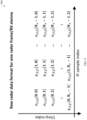
- FIG. 9 illustrates an example raw radar data format 900 for one radar frame of one receive antenna in accordance with an embodiment of this disclosure.
- the embodiment of the raw radar data format 900 shown in FIG. 9 is for illustration only, and other embodiments can be used without departing from the scope of this disclosure.
- the raw radar data format 900 relates to the signal processing performed on the radar signal (such as the radar data 740 ) to obtain (for example, extract) the features that are used for gesture detection. Examples of features extracted from the raw radar data format 900 and used for gesture detection include: TVD, TAD, and low-dimensional Doppler extracted from the TVD.
- TVD and TAD are used as features for gesture classification (i.e., used by the GC 730 ).
- FIGS. 10 and 11 show how to obtain the TVD and TAD from the radar data, respectively.
- FIG. 10 A illustrates a process 1000 of generating a TVD column from a frame, such as the radar frame 900 of FIG. 9 , in accordance with an embodiment of this disclosure.
- FIG. 10 B illustrates a range profile 1022 , a range doppler map (RDM) 1028 , and the TVD 1030 generated by the process of FIG. 10 A , in accordance with an embodiment of this disclosure.
- RDM range doppler map
- FIGS. 10 A and 10 B are generally referred to as FIG. 10 .
- the embodiment of the TVD column generation process 1000 shown in FIG. 10 is for illustration only, and other embodiments can be used without departing from the scope of this disclosure.
- the radar module 1002 uses the clutter removed and zero-Doppler nulled RDM for a given frame 1022 a to generate a range profile 1022 curve by summing the power across all Doppler bins.
- the x-axis of the range profile 1022 represents the Range bins (e.g., 32 bins are illustrated), and the y-axis represents the power (in dBm) across all Doppler bins.
- the range profile 1022 is compared with a detection threshold to extract the range information of the target of interest.
- the first detected peak 1024 in the range profile 1022 indicates the location of the target object. Specifically, the first peak above the detection threshold is considered to contain the moving finger. This is based on the observation that in a typical experimental use case, the gesture is the closest moving target to the radar.
- the detection threshold itself varies with range to accommodate the leakage residual in the first few taps. As such, the detection threshold on the first few taps is chosen higher than the subsequent taps. The number of taps and the amount of offset applied to the detection threshold is determined based on measurements.
- these thresholds depend on the choice of the radar parameters and remain consistent across various radars and across time. Thus, these thresholds, once determined, can be used in various radar platforms and across time.
- the x-axis of the range profile 1022 represents time measured in frame numbers (e.g., two seconds are illustrated as 50 frames), and the y-axis represents the velocity (in centimeters per second). That is, the Doppler dimension of the TVD is the velocity dimension represented by the y-axis.
- the TVD 1030 includes the TVD column 1020 for a given frame, such as the frame corresponding to the received radar signal 1004 .
- the process 1100 of TAD generation is shown in FIG. 11 assumes the target object is located at an angle ⁇ 0 with respect to the end fire of a ULA.
- the beat signal 1104 for a receive antenna having an index i is expressed according to Equation 29, where ⁇ i denotes the round trip time delay to the i-th receive antenna.
- the round trip time delay ⁇ i is expressed according to Equation 30 as antenna index i ⁇ 1.
- the spatial angle information is easily extracted using the phases of the beat signals across the antennas.
- the sampled ADC output corresponding to the n-th chirp for the i-th antenna is expressed according to Equation 32.
- x i,j[k,n] r i b ( n ⁇ t c +kT s ) (32)
- R i,f [X i,0,f ,X i,1,f , . . . ,X i,N c ⁇ 1,f ] T (33)
- B f,b 0 [r 1,f,b 0 ,r 2,f,b 0 , . . . ,r N r ,f,b 0 ] T (34)
- the co-variance matrix of the received signal across the N r antennas is empirically obtained, mathematically, as expressed in Equation 35.
- the MUSIC algorithm is applied to the C f,b 0 , to obtain the spatial spectrum of the target at bin b 0 .
- Other direction estimation algorithms can also be used instead of the MUSIC algorithm.
- the radar module 1108 decomposes C f,b 0 using the eigenvalue decomposition and separate the signal and noise subspaces as according to Equation 36, where ⁇ s,f,b 0 represents a diagonal matrix containing the eigenvalues of C f,b 0 corresponding to the signal and ⁇ n 2 is the noise variance.
- the first and second end detectors 1210 and 1220 enable the ADM 720 to perform the end-detection method 1300 , in which method the GC 730 is triggered to operate in response to a determination that two conditions are concurrently satisfied, those two conditions being (i) that gesture activity has started and (ii) that the gesture activity has ended.
- the ADM triggers operation of the GC 730 when performance of a gesture is completed.
- the binary classifier 1304 predicts whether a gesture has ended or not. As the TVD is updated at the frame rate according to radar parameters, the binary classifier 1304 will operate at the same or lower rate than the frame rate.
- the TVD 1402 - 1410 are described as being used to train a binary classifier 1304 that makes one prediction 1308 per frame.
- the prediction 1308 by the binary classifier 1304 includes either an indicator of “class 0” that implies that the gesture has not ended, or an indicator of “class 1” that implies that the gesture has ended.
- the TVDs 1402 - 1410 were generated as “class 0” and “class 1” samples.
- the ground truth ending 1412 of the gesture is marked (illustrated as a red vertical line), for example, marked by a user of a training system or an engineer who is training the binary classifier.
- the ground truth endings 1412 , 1414 , 1416 , 1418 , and 1420 are marked based on visual observations in FIGS. 14 A- 14 E , respectively.
- FIG. 15 C illustrates the PWDNM feature 1520 of the no-activity sample TVD 1410 of FIG. 14 E .
- the PWDNM feature 1520 has a non-negligible value form almost for all j ⁇ 1, 2, . . . , 50. Though there is no-activity, the normalization means that the largest value will be 1. As such, large values for all j are an indication that the gesture has not ended.
- the PWDNM feature 1520 corresponds to a “class 0” sample, which is the TVD 1410 of FIG. 14 E .
- low-dimensional Doppler features can be extracted from the TVD (in dB scale or in linear domain) and considered. These low-dimensional Doppler features may vary in performance, and final selection of which feature is to be used by the second end-detector 1220 ( FIG. 12 A ) can be based on the performance, such as the classification accuracy of the binary classifier trained using the feature.
- PWDDNabs Power weighted absolute Doppler with Doppler normalization
- PWDDN Power weighted Doppler with Doppler normalization
- PWDNM Power weighted Doppler with max normalization
- FIG. 16 A illustrates an example TVD 1600 representing a gesture that includes four bursts 1602 - 1608 in accordance with an embodiment of this disclosure.
- the third end detector 1230 executes a method to determine the end of a gesture, which includes learning patterns that are specific to gestures and that are not present within non-gesture activity nor within invalid gesture activity. One such pattern is the bursty behavior of the gestures.
- third end detector 1230 executes a method ( 1800 of FIG. 18 ) to determine the bursts.
- FIGS. 16 B and 16 C aid in describing the process of FIG. 17 .
- FIG. 16 B illustrates another example TVD 1650 .
- FIG. 16 C illustrates a graph 1660 of a number of signal elements (i.e., signal pixels) as a function of frame index (i.e., x-axis) in the TVD 1650 of FIG. 16 B .
- a curve 1662 representing the number of signal elements includes a first peak 1664 .
- the embodiments of the TVDs 1600 and 1650 and graph 1660 shown in FIG. 16 A- 16 C are for illustration only, and other embodiments can be used without departing from the scope of this disclosure.
- ADM obtains raw radar data.
- the raw radar data is processed into a range-Doppler map, such as the RDM 1028 of FIG. 10 .
- third end-detector 1230 identifies and selects the Doppler corresponding to a first peak tap (e.g., peak 1664 of FIG. 16 C ).
- Subsequent processing at block 1706 is based on the Doppler elements in this 1 st peak tap.
- the Doppler elements e.g., all Doppler elements of the peak 1664
- the detection threshold is based on noise threshold and potentially some offset calculated from measurements that captures the self-interference between the transmit and receive antennas of the radar.
- the Doppler elements with energy clearly greater than the noise-level e.g., 5 dB
- the other Doppler elements e.g., with power less than or equal to the noise-level
- the number of signal elements are counted.
- the counted number of signal elements from the example TVD 1650 is shown by the curve 1662 of FIG. 16 B .
- the third end-detector 1230 determines whether the movement frame counter equals N, which is a threshold number for movement frames. In response to a determination that the movement frame counter does not equal N, the method returns to block 1802 to process a next frame.
- a burst start is declared as the current frame. Block 1818 is the same as or similar procedure as block 1808 . From block 1818 , the method returns to block 1802 to process a next frame.
- FIG. 19 illustrates a method 1900 of an ML-based ADM using binary classifier based on burst information in an online operation in accordance with an embodiment of this disclosure.
- the process 1900 is executed by the ADM, particularly, by the third end-detector 1230 .
- the embodiment of the process 1900 shown in FIG. 19 is for illustration only, and other embodiments can be used without departing from the scope of the present disclosure.
- the binary classifier (for example, a binary classifier 1920 within the third end-gesture detector 1230 ) is then trained based on these features extracted from the TVDs.
- the online operation of the ADM using burst based training is shown in FIG. 19 .
- the timer is run or continues to run (at block 1926 ).
- the timer is run or continues to run (at block 1926 ).
- the GC 730 is triggered at block 1930 .
- the ADM sends process the updated feature vector 1912 to the GC 730 , which upon receipt triggers the GC 730 to classify the updated feature vector 1912 .
- the process 1900 returns to block 1902 and repeats.
- the timer can be in frames, in which case the value of the timer can be set similar to N, i.e., 11.
- the burst information based third end-gesture detector 1230 may call the binary classifier 1920 only when the end of a burst is detected.
- Such embodiments provide an advantage help reduce some computational complexity in terms of the number of calls to the ADM binary classifier 1920 .
- FIGS. 20 - 25 illustrate embodiments of this disclosure in which the ADM 724 includes a gating mechanism (for example, as shown in FIG. 7 A ).
- the ADM 724 and its gating mechanisms will be described in this section of the disclosure, and the description of the gesture mode triggering mechanism 710 and GC 730 apply equally to the end-to-end system 700 with the gating mechanism without a duplicative description.
- the ADM 724 (with gating) can be compared to the ADM 722 (without gating).
- the above-described first, second, and third end-gesture detectors 1210 , 1220 , 1230 are ML-based ADM modules that are operational and generate predictions (namely, 1922 or 1924 of FIG. 19 or 1308 of FIG. 13 A ).
- simple gating mechanisms further reduce the operational complexity of the ADM 720 operation/inferences. This further reduction of complexity is relative to the complexity of the ADM 722 (without gating).
- Gating mechanisms are beneficial not only in the online operation in terms of reducing the computational complexity, but also because the ADM's 724 (with gating) is not dealing with the cases (i.e., frames) that are discarded by with the gating mechanisms, the training process of the ML models within the ADM 724 (with gating) is simpler, as the ADM's 724 models (associated with binary classifier 725 B) needs to be trained to deal with fewer cases than the ADM's 722 (without gating) models that are associated with binary classifier 725 A.
- FIG. 20 illustrates a block diagram of the ADM 724 including one or more gating mechanisms 2010 - 2060 in accordance with an embodiment of this disclosure.
- the embodiment of the ADM 2000 shown in FIG. 20 is for illustration only, and other embodiments can be used without departing from the scope of this disclosure.
- Each embodiment of the different gating mechanisms 2010 - 2060 activate and deactivate the end detector 728 ( FIG. 7 ) of the ADM, ensuring that the ADM 720 is activated when gesture activities are detected and deactivated when non-gesture activities or no activities are detected.
- FIGS. 21 - 26 illustrate various examples of gating methods executed by the respective gating mechanisms 2010 - 2060 in accordance with this disclosure.
- the embodiments of the gating methods shown in FIGS. 21 - 26 are for illustration only, and other embodiments can be used without departing from the scope of this disclosure.
- Several embodiments execute a gating process that can be used to reduce the computational complexity and the training process of the ML-based ADM 720 .
- any combination of the gating mechanisms can be used because some of the gating mechanisms can be used to deactivate an ADM that is already in operation, and others can be used to active an ADM that is not yet in operation.
- FIG. 21 illustrates a gating process 2100 of the strong-tap based gating mechanism 2010 in accordance with an embodiment of this disclosure.
- the process 2100 is executed by the ADM 724 , particularly, by the strong-tap based gating mechanism 2010 .
- the strong-tap based gating mechanism 2010 is also referred to as a gating mechanism based on first peak tap detection or as a gating mechanism based on strongest detected tap.
- Different types of gestures are performed at different distance ranges from the electronic device 200 (e.g., smartphone). Particularly, micro-gestures that are gestures performed with finger level movements will typically be performed at a few centimeters from the device, e.g., 5-20 cm.
- the process 2100 exploits this information about the typical use case can be used to gate (for example, consider any activity outside this typical 5-20 cm range of distances as a non-gesture movement, and hence there is no need to trigger the ADM for movements outside this range. Accordingly, the process 2100 can be classified as a distance-based gating process.
- the method 2100 begins with obtaining raw sensor data (at block 2102 ), and processing the raw radar data into a range-Doppler map (at block 2104 ).
- the procedures performed at blocks 2102 and 2104 can be the same or similar procedures as blocks 1802 and 1804 of FIG. 18 , respectively.
- the first peak tap is determined.
- the strongest tap is determined at block 2106 .
- the procedure performed at block 2106 can be the same or similar procedure as block 1704 of FIG. 17 .
- a reason for using the first peak tap instead of the strongest tap is that generally there is no target object between the radar and the hand of the user while performing gestures (particularly true for micro-gestures), and as such first peak tap is likely to be the tap of interest, whereas the strongest tap could be based on some reflection from the body of a close by user etc.
- the strong-tap based gating mechanism 2010 determines whether the ADM is active. Specifically, at block 2110 , if the ADM is active, then the method proceeds to block 2114 , at which is no action required. If the ADM is not active, the method proceeds from block 2110 to block 2116 , at which the strong-tap based gating mechanism 2010 triggers the end detector 728 .
- the method 2100 proceeds to 2118 .
- strong-tap based gating mechanism 2010 deactivates the ADM, namely, the end detector 728 , and the method 2100 returns to block 2102 to repeat.
- the method 2100 proceeds to block 2120 , at which the strong-tap based gating mechanism 2010 stops the ADM that is already in operation and does not trigger the GC 730 .
- FIG. 22 illustrates a range variation based gating mechanism in accordance with an embodiment of this disclosure.
- the process 2200 is executed by the range-variation gating mechanism 2020 ( FIG. 20 ). This is a gating process 2200 based on variation in range during the gesture, and consequently can be classified as a distance-based gating process.
- the measure of range variation is the difference between the largest entry and smallest entry. If this variation (i.e., variation in taps) is greater than M, then the radar data 740 is determined to be an invalid gesture or non-gesture activity, and the method returns to block 2202 . If the variation in taps is not less than M (No path), the method proceeds to block 2212 , at which the range-variation gating mechanism 2020 determines whether the ADM is working. If the ADM is working, the method proceeds to block 2214 , at which deactivation of the ADM without triggering the GC 730 is performed. Alternatively, if the ADM is not working, then the method proceeds to block 2216 , at which is no action required.
- FIG. 23 illustrates a gating process 2300 of an average TVD based gating mechanism 2030 in accordance with an embodiment of this disclosure.
- This gating process 2300 monitors for dynamic gestures, namely, gestures based on and characterized by movements. Therefore, it is possible that the hand of a user is within a specific range, hence satisfying the conditions for range-based gating, yet there is no need to trigger the ADM to operate the end detector 728 ( FIG. 7 ) due to a lack of activity. This lack of activity of no activity condition can be determined based on the TVD.
- the method 2300 begins with obtaining raw sensor data (at block 2302 ), and processing the raw radar data into a time velocity diagram (at block 2304 ). First the raw radar data is processed to obtain a TVD (for example, 1030 of FIG. 10 ).
- the average value of the TVD is obtained, which is a scalar.
- the TVD can be denoted as T ⁇ R N ⁇ M , then the average of the TVD is expressed according to Equation 47, where T nm represents the entry on the nth row and mth column in T.
- this average of the TVD is compared to a threshold.
- the average TVD based gating mechanism 2030 in response to the average TVD based gating mechanism 2030 determining that the value of average of the TVD is greater than the threshold, then the average TVD based gating mechanism 2030 triggers the ADM to operate the end detector 728 .
- the parameter (for example, only parameter) controlling the performance of this average TVD based gating mechanism 2030 is the threshold.
- This threshold can be based on the noise level plus an offset that controls the false alarm rate. The larger the offset, the lesser the chance of the false alarm.
- the noise level can be obtained by obtaining a range profile (e.g., 1022 ) from the range-Doppler map (e.g., 1028 ).
- FIG. 25 illustrates a gating method 2500 performed by a burst detection based gating mechanism 2050 in accordance with an embodiment of this disclosure.
- the activity of dynamic gestures is bursty, as described above in the context of ML based ADM (e.g., end detectors 1210 , 1220 , and 1230 of FIG. 12 A ).
- This burst information can also be used for gating. Any activity that has a shorter duration than a valid burst is likely not to be a part of a valid gesture.
- the gating method 2500 determines whether radar data incudes a burst or not.
- FIG. 26 illustrates a gating method 2600 performed by an angle based gating mechanism 2060 in accordance with an embodiment of this disclosure.
- the method 2600 begins with obtaining raw sensor data (at block 2602 ), and processing the raw radar data (at block 2304 ), for example, into a time angle diagram.
- the CNN-based architecture 2700 includes two 2D-convolutional layers, two MaxPool layers, and two Dense layers.
- one layer 2704 includes 64 channels and a kernel size of (7,8)
- another layer 2710 includes 32 channels and a kernel size of (2,3).
- one layer 2708 includes a kernel size of (4,4)
- another layer 2714 includes a kernel size of (2,2).
- one layer 2716 includes a size of 32, and another layer 2718 includes a size of 6 (corresponding to the number of gestures in the gesture vocabulary 800 of FIG. 8 ).
- a couple of BlurPool layers 2706 and 2712 are additionally included in this CNN-based architecture 2700 . That is, if ADM exhibits poor performance of by incorrectly indicating that a gesture has ended, the BlurPool layers increase the likelihood of an accurate gesture classification.
- Both of the BlurPool layers 2706 and 2712 have a kernel size of (3, 3).
- the processor 240 activates the gesture recognition mode.
- Activating the gesture recognition mode can include sub-processes, such as the procedures at blocks 2822 , 2824 , 2826 , and 2828 .
- the processor 240 obtains radar data 740 while the gesture recognition mode is activated.
- the radar data includes time-velocity data and/or time-angle data.
- activating the gesture recognition mode enables the processor 240 to determine whether the obtained radar data corresponds to non-gesture activities or gesture-related activities.
- the processor 240 determines whether the obtained radar data corresponds to non-gesture activities or gesture-related activities.
- the processor 240 activates an ADM to detect the end of the gesture based on information extracted from the TVD.
- the processor 240 deactivates or maintains the ADM in a deactivated state.
- the processor 240 detects a start and an end of a gesture based on the TVD of the obtained radar data. More particularly, at block 2832 , the processor 240 detects a start of the gesture. At block 2834 , the processor 240 determines whether the end of the gesture is detected. In response to a determination that the end of the gesture is not detected, the method 2800 repeats block 2834 . In response to a determination that the end of the gesture is detected, the method proceeds to block 2840 , at which the processor 240 classifies the gesture. In certain embodiments, the processor 240 (using the second end detector 1220 of FIG. 12 A ) detects the end of the gesture by using low-dimensional Doppler features extracted from the TVD of the obtained radar data.
- the processor 240 outputs an event indicator 770 indicating that a user of the electronic device performed the gesture classified.
- the event indicator 770 can be an identifier of the fourth probability or another identifier of the double pinch gesture 808 .
Landscapes
- Engineering & Computer Science (AREA)
- Remote Sensing (AREA)
- Radar, Positioning & Navigation (AREA)
- Physics & Mathematics (AREA)
- General Physics & Mathematics (AREA)
- Theoretical Computer Science (AREA)
- Computer Networks & Wireless Communication (AREA)
- General Engineering & Computer Science (AREA)
- Human Computer Interaction (AREA)
- Computer Vision & Pattern Recognition (AREA)
- General Health & Medical Sciences (AREA)
- Health & Medical Sciences (AREA)
- Multimedia (AREA)
- Evolutionary Computation (AREA)
- Artificial Intelligence (AREA)
- Electromagnetism (AREA)
- Social Psychology (AREA)
- Psychiatry (AREA)
- Biodiversity & Conservation Biology (AREA)
- Biomedical Technology (AREA)
- Molecular Biology (AREA)
- Life Sciences & Earth Sciences (AREA)
- Computing Systems (AREA)
- Databases & Information Systems (AREA)
- Medical Informatics (AREA)
- Software Systems (AREA)
- User Interface Of Digital Computer (AREA)
Abstract
Description
r=2R/c (5)
ΔR=cΔτ/2=cT P/2 (6)
P(f)˜(sin(πfT P)/(πfT P))2 (7)
B=1/T P (8)
ΔR=c/2B (9)
B=f min −f max (10)
x n =[{x[k,n]} k=0 N
k*=argmax∥X n∥2 (25)
R∈
for 0≤k≤N s−1 and 0≤n≤N c−1 (28)
| TABLE 1 |
| Notation |
| Letter or Symbol | Typeface | What is represented | ||
| x | bold lowercase | column vectors | ||
| X | bold uppercase | matrices | ||
| x and X | non-bold letters | Scaler | ||
| T | superscript | transpose | ||
| * | superscript | conjugate transpose | ||
Sτ i ≈Sτ 1 ,∀i (31)
x i,n,f =[{x i,f [k,n]} k=0 N
where x i,j[k,n] =r i
R i,f =[X i,0,f ,X i,1,f , . . . ,X i,N
B f,b
C f,b
μ∈1×50, with μ[j]=τ Z kT[k,j] (41)
μl∈1×50, with μ[j]=10 log10( 1/64Σhd kT l [k,j]) (42)
Claims (20)
Priority Applications (3)
| Application Number | Priority Date | Filing Date | Title |
|---|---|---|---|
| US18/063,055 US12026319B2 (en) | 2022-04-13 | 2022-12-07 | Dynamic gesture recognition using mmWave radar |
| PCT/KR2023/000802 WO2023200086A1 (en) | 2022-04-13 | 2023-01-17 | Method and apparatus for recognizing gesture of user |
| EP23788442.4A EP4409382A4 (en) | 2022-04-13 | 2023-01-17 | METHOD AND DEVICE FOR RECOGNIZING USER GESTURES |
Applications Claiming Priority (2)
| Application Number | Priority Date | Filing Date | Title |
|---|---|---|---|
| US202263330603P | 2022-04-13 | 2022-04-13 | |
| US18/063,055 US12026319B2 (en) | 2022-04-13 | 2022-12-07 | Dynamic gesture recognition using mmWave radar |
Publications (2)
| Publication Number | Publication Date |
|---|---|
| US20230333660A1 US20230333660A1 (en) | 2023-10-19 |
| US12026319B2 true US12026319B2 (en) | 2024-07-02 |
Family
ID=88307774
Family Applications (1)
| Application Number | Title | Priority Date | Filing Date |
|---|---|---|---|
| US18/063,055 Active US12026319B2 (en) | 2022-04-13 | 2022-12-07 | Dynamic gesture recognition using mmWave radar |
Country Status (3)
| Country | Link |
|---|---|
| US (1) | US12026319B2 (en) |
| EP (1) | EP4409382A4 (en) |
| WO (1) | WO2023200086A1 (en) |
Families Citing this family (5)
| Publication number | Priority date | Publication date | Assignee | Title |
|---|---|---|---|---|
| US20230419733A1 (en) * | 2022-06-22 | 2023-12-28 | Yannick VERDIE | Devices and methods for single or multi-user gesture detection using computer vision |
| US20240201779A1 (en) * | 2022-12-15 | 2024-06-20 | Amazon Technologies, Inc. | Presence detection with dynamic radar operating modes |
| CN117519474B (en) * | 2023-11-06 | 2024-05-14 | 中国人民解放军陆军工程大学 | A radar gesture feature acquisition method considering motion prior |
| CN117310646B (en) * | 2023-11-27 | 2024-03-22 | 南昌大学 | Lightweight human posture recognition method and system based on indoor millimeter wave radar |
| US20250211459A1 (en) * | 2023-12-22 | 2025-06-26 | Intel Corporation | Virtual environment modifications based on user behavior or context |
Citations (19)
| Publication number | Priority date | Publication date | Assignee | Title |
|---|---|---|---|---|
| US20120280900A1 (en) * | 2011-05-06 | 2012-11-08 | Nokia Corporation | Gesture recognition using plural sensors |
| US9335825B2 (en) | 2010-01-26 | 2016-05-10 | Nokia Technologies Oy | Gesture control |
| US10514770B2 (en) | 2016-06-17 | 2019-12-24 | Texas Instruments Incorporated | Hidden Markov model-based gesture recognition with FMCW radar |
| WO2020191070A1 (en) | 2019-03-21 | 2020-09-24 | Qualcomm Incorporated | Radar for detecting human body part |
| US20200300996A1 (en) | 2019-03-22 | 2020-09-24 | Apple Inc. | Systems and methods for object detection by radio frequency systems |
| US20200336222A1 (en) | 2019-04-16 | 2020-10-22 | Qualcomm Incorporated | Method and apparatus for maximum permissible exposure proximity sensor fault detection |
| US20200356178A1 (en) * | 2019-05-06 | 2020-11-12 | Samsung Electronics Co., Ltd. | Methods for gesture recognition and control |
| US20210027049A1 (en) | 2019-07-26 | 2021-01-28 | Google Llc | Authentication Management Through IMU and Radar |
| US20210026454A1 (en) * | 2019-07-26 | 2021-01-28 | Google Llc | Robust Radar-Based Gesture-Recognition by User Equipment |
| US20210096653A1 (en) | 2015-10-06 | 2021-04-01 | Google Llc | Advanced Gaming and Virtual Reality Control Using Radar |
| US11030459B2 (en) | 2019-06-27 | 2021-06-08 | Intel Corporation | Methods and apparatus for projecting augmented reality enhancements to real objects in response to user gestures detected in a real environment |
| CN113313040A (en) | 2021-06-04 | 2021-08-27 | 福州大学 | Human body posture identification method based on FMCW radar signal |
| US20210270936A1 (en) | 2020-02-27 | 2021-09-02 | Samsung Electronics Co., Ltd. | Method and apparatus of radar-based activity detection |
| US20210293927A1 (en) | 2020-03-20 | 2021-09-23 | Aptiv Technologies Limited | Object classification using low-level radar data |
| US20210342008A1 (en) | 2019-08-30 | 2021-11-04 | Google Llc | Context-Sensitive Control of Radar-Based Gesture-Recognition |
| CN113963441A (en) | 2021-10-25 | 2022-01-21 | 中国科学技术大学 | A method and system for gesture recognition of millimeter wave radar based on cross-domain enhancement |
| US20220082684A1 (en) | 2021-09-07 | 2022-03-17 | Hangzhou Innovation Research Institute of Beijing University of Aeronautics and Astronautics | Millimeter wave radar gesture recognition method and device based on trajectory judgment |
| US11416080B2 (en) * | 2018-09-07 | 2022-08-16 | Samsung Electronics Co., Ltd. | User intention-based gesture recognition method and apparatus |
| US11816101B2 (en) * | 2014-08-22 | 2023-11-14 | Google Llc | Radar recognition-aided search |
Family Cites Families (1)
| Publication number | Priority date | Publication date | Assignee | Title |
|---|---|---|---|---|
| US10845477B2 (en) | 2017-05-10 | 2020-11-24 | Google Llc | Power management using a low-power radar |
-
2022
- 2022-12-07 US US18/063,055 patent/US12026319B2/en active Active
-
2023
- 2023-01-17 WO PCT/KR2023/000802 patent/WO2023200086A1/en unknown
- 2023-01-17 EP EP23788442.4A patent/EP4409382A4/en active Pending
Patent Citations (19)
| Publication number | Priority date | Publication date | Assignee | Title |
|---|---|---|---|---|
| US9335825B2 (en) | 2010-01-26 | 2016-05-10 | Nokia Technologies Oy | Gesture control |
| US20120280900A1 (en) * | 2011-05-06 | 2012-11-08 | Nokia Corporation | Gesture recognition using plural sensors |
| US11816101B2 (en) * | 2014-08-22 | 2023-11-14 | Google Llc | Radar recognition-aided search |
| US20210096653A1 (en) | 2015-10-06 | 2021-04-01 | Google Llc | Advanced Gaming and Virtual Reality Control Using Radar |
| US10514770B2 (en) | 2016-06-17 | 2019-12-24 | Texas Instruments Incorporated | Hidden Markov model-based gesture recognition with FMCW radar |
| US11416080B2 (en) * | 2018-09-07 | 2022-08-16 | Samsung Electronics Co., Ltd. | User intention-based gesture recognition method and apparatus |
| WO2020191070A1 (en) | 2019-03-21 | 2020-09-24 | Qualcomm Incorporated | Radar for detecting human body part |
| US20200300996A1 (en) | 2019-03-22 | 2020-09-24 | Apple Inc. | Systems and methods for object detection by radio frequency systems |
| US20200336222A1 (en) | 2019-04-16 | 2020-10-22 | Qualcomm Incorporated | Method and apparatus for maximum permissible exposure proximity sensor fault detection |
| US20200356178A1 (en) * | 2019-05-06 | 2020-11-12 | Samsung Electronics Co., Ltd. | Methods for gesture recognition and control |
| US11030459B2 (en) | 2019-06-27 | 2021-06-08 | Intel Corporation | Methods and apparatus for projecting augmented reality enhancements to real objects in response to user gestures detected in a real environment |
| US20210026454A1 (en) * | 2019-07-26 | 2021-01-28 | Google Llc | Robust Radar-Based Gesture-Recognition by User Equipment |
| US20210027049A1 (en) | 2019-07-26 | 2021-01-28 | Google Llc | Authentication Management Through IMU and Radar |
| US20210342008A1 (en) | 2019-08-30 | 2021-11-04 | Google Llc | Context-Sensitive Control of Radar-Based Gesture-Recognition |
| US20210270936A1 (en) | 2020-02-27 | 2021-09-02 | Samsung Electronics Co., Ltd. | Method and apparatus of radar-based activity detection |
| US20210293927A1 (en) | 2020-03-20 | 2021-09-23 | Aptiv Technologies Limited | Object classification using low-level radar data |
| CN113313040A (en) | 2021-06-04 | 2021-08-27 | 福州大学 | Human body posture identification method based on FMCW radar signal |
| US20220082684A1 (en) | 2021-09-07 | 2022-03-17 | Hangzhou Innovation Research Institute of Beijing University of Aeronautics and Astronautics | Millimeter wave radar gesture recognition method and device based on trajectory judgment |
| CN113963441A (en) | 2021-10-25 | 2022-01-21 | 中国科学技术大学 | A method and system for gesture recognition of millimeter wave radar based on cross-domain enhancement |
Non-Patent Citations (1)
| Title |
|---|
| International Search Report and Written Opinion dated Apr. 24, 2023 regarding International Application No. PCT/KR2023/000802, 8 pages. |
Also Published As
| Publication number | Publication date |
|---|---|
| WO2023200086A1 (en) | 2023-10-19 |
| US20230333660A1 (en) | 2023-10-19 |
| EP4409382A4 (en) | 2025-01-22 |
| EP4409382A1 (en) | 2024-08-07 |
Similar Documents
| Publication | Publication Date | Title |
|---|---|---|
| US12026319B2 (en) | Dynamic gesture recognition using mmWave radar | |
| US11506753B2 (en) | Systems and methods for radar based face authentication anti-spoofing | |
| Choi et al. | People counting using IR-UWB radar sensor in a wide area | |
| US20230041835A1 (en) | Radio frequency exposure estimation with radar for mobile devices | |
| US11871299B2 (en) | Self-supervised passive positioning using wireless data | |
| US11860298B2 (en) | Radar leakage measurement update | |
| US12241963B2 (en) | Angle estimation with multi-frame processing for radar on mobile devices | |
| US11506754B2 (en) | Radar based pattern code identification | |
| US12192034B2 (en) | System and method for distance measurement using UWB radar | |
| US12282083B2 (en) | Multi-frame radar processing for robust body part detection for mobile devices | |
| US11751008B2 (en) | Angle of arrival capability in electronic devices | |
| CN113534946A (en) | Non-contact gesture recognition method | |
| US12276747B2 (en) | Radar for full-blockage detection of radio frequency modules in mobile devices | |
| US20250004563A1 (en) | Magnitude determination for system commands in a gesture recognition system | |
| US20240028127A1 (en) | Methods and apparatus for enabling dynamic gesture input for micro-gesture recognition | |
| US20240053463A1 (en) | Methods and apparatuses for latency reduction in gesture recognition using mmwave radar | |
| US20230384420A1 (en) | Apparatus and method for power saving in gesture recognition using mmwave radar | |
| US20240361841A1 (en) | Non-gesture rejections using radar | |
| US20240370094A1 (en) | Burst-based non-gesture rejection in a micro-gesture recognition system | |
| US20250118186A1 (en) | Ultra-wideband-based fall detection | |
| US20250061745A1 (en) | Macro gesture recognition accuracy enhancements | |
| US20240310504A1 (en) | Presence detection using uwb radar | |
| US12366925B2 (en) | Robustifying radar-based gesture recognition solution using contextual information | |
| US20230039849A1 (en) | Method and apparatus for activity detection and recognition based on radar measurements | |
| Shi et al. | Design and implementation of non-intrusive stationary occupancy count in elevator with wifi |
Legal Events
| Date | Code | Title | Description |
|---|---|---|---|
| AS | Assignment |
Owner name: SAMSUNG ELECTRONICS CO., LTD., KOREA, REPUBLIC OF Free format text: ASSIGNMENT OF ASSIGNORS INTEREST;ASSIGNORS:ALI, ANUM;PARIDA, PRIYABRATA;VA, VUTHA;AND OTHERS;REEL/FRAME:062018/0213 Effective date: 20221207 |
|
| STPP | Information on status: patent application and granting procedure in general |
Free format text: RESPONSE TO NON-FINAL OFFICE ACTION ENTERED AND FORWARDED TO EXAMINER |
|
| STPP | Information on status: patent application and granting procedure in general |
Free format text: FINAL REJECTION MAILED |
|
| STPP | Information on status: patent application and granting procedure in general |
Free format text: RESPONSE AFTER FINAL ACTION FORWARDED TO EXAMINER |
|
| STPP | Information on status: patent application and granting procedure in general |
Free format text: NOTICE OF ALLOWANCE MAILED -- APPLICATION RECEIVED IN OFFICE OF PUBLICATIONS |
|
| STPP | Information on status: patent application and granting procedure in general |
Free format text: AWAITING TC RESP., ISSUE FEE NOT PAID |
|
| STPP | Information on status: patent application and granting procedure in general |
Free format text: AWAITING TC RESP, ISSUE FEE PAYMENT RECEIVED |
|
| STPP | Information on status: patent application and granting procedure in general |
Free format text: PUBLICATIONS -- ISSUE FEE PAYMENT VERIFIED |
|
| STCF | Information on status: patent grant |
Free format text: PATENTED CASE |