BACKGROUND
1. Technical Field
The present disclosure relates to an information processing device such as a laptop personal computer.
2. Description of the Related Art
For example, Patent Literature (PTL) 1 discloses a laptop personal computer (information processing device) to which a hard disk (storage device) is removably attached. The laptop personal computer includes a body provided in its bottom surface with a recessed housing part for storing a hard disk. The recessed housing part is provided on its side surface with a connector connected to an interface connector of the hard disk. That is, the interface connector of the hard disk and the connector of the body are configured to be connected in a direction orthogonal to a thickness direction of the body.
PTL 1 is Unexamined Japanese Patent Publication No. 2007-250149.
SUMMARY
Unfortunately, the information processing device described in PTL 1 is required to slide the hard disk toward the connector of the body in a direction orthogonal to the thickness direction of the body, i.e., in a width direction or a depth direction of the body to connect the interface connector of the hard disk to the connector of the body after the hard disk is stored in the housing part. For a stroke of the movement, the body is required to have a movement space that is only used when the hard disk is attached or detached. This movement space limits a space for disposing components other than the storage device.
Thus, an object of the present disclosure is to fabricate an attaching and detaching structure of a storage device in a body of an information processing device to which the storage device is removably attached, the attaching and detaching structure requiring no movement space used for the storage device only when the storage device is attached and detached.
An information processing device provided by an aspect of the present disclosure includes a body in a plate shape, and a storage unit that includes a storage device and is removably attached to the body. The body includes a housing part in a recessed shape that is recessed in a thickness direction of the body, the housing part storing the storage unit, and a first connector provided on a bottom surface of the housing part. The storage unit includes a second connector connected to the first connector to be removably attached in the thickness direction.
The present disclosure enables fabricating the attaching and detaching structure of the storage device in the body of the information processing device to which the storage device is removably attached, the attaching and detaching structure requiring no movement space used for the storage device only when the storage device is attached and detached.
BRIEF DESCRIPTION OF DRAWINGS
FIG. 1 is a perspective view of an information processing device according to an exemplary embodiment of the present disclosure.
FIG. 2 is a perspective view illustrating a lower surface of a body of the information processing device.
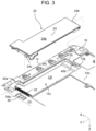
FIG. 3 is a partial perspective view of the body of the information processing device, illustrating a state in which a storage unit is removed from the body.
FIG. 4 is a partial perspective view of the body of the information processing device, illustrating a state in which the storage unit is removed from the body as viewed from a viewpoint different from that in FIG. 3 .
FIG. 5 is a partial bottom view of the body of the information processing device, illustrating a housing part for the storage unit.
FIG. 6 is a perspective view of the storage unit.
FIG. 7 is a perspective view of the storage unit viewed from a viewpoint different from that of FIG. 6 .
FIG. 8 is an exploded perspective view of the storage unit.
FIG. 9 is a perspective view of a lock member and a stopper plate provided in the body.
DETAILED DESCRIPTION
An exemplary embodiment will be described below in detail with reference to the drawings as appropriate. However, unnecessarily detailed description may be omitted. For example, the detailed description of already well-known matters and the redundant description of a configuration substantially identical to the already-described configuration may be omitted. A reason for this is to avoid unnecessary redundancy of the following description and to facilitate understanding of those skilled in the art.
The inventors of the present disclosure provide the accompanying drawings and the following description for those skilled in the art to fully understand the present disclosure, and do not provide them to intend to limit the subject matter described in the scope of claims
Hereinafter, an information processing device according to an exemplary embodiment of the present disclosure will be described with reference to FIGS. 1 to 9 .
FIG. 1 illustrates an information processing device according to an exemplary embodiment of the present disclosure. The drawings each show an X-Y-Z coordinate system that is for facilitating understanding of the exemplary embodiment of the present disclosure, and that does not limit the exemplary embodiment. The X-Y-Z coordinate system includes an X-axis direction that is a width direction of the information processing device, a Y-axis direction that is a depth direction, and a Z-axis direction that is a thickness direction.
As illustrated in FIG. 1 , information processing device 10 according to the present exemplary embodiment is a so-called laptop personal computer, and includes body 12 and display 14 rotatably attached to body 12.
Body 12 of information processing device 10 has a plate shape that is smaller in size in the thickness direction (Z-axis direction) than in the width direction (X-axis direction) and in the depth direction (Y-axis direction). Body 12 incorporates a central processing unit (CPU) and others, and is provided on its upper surface 12 a with keyboard 16.
FIG. 2 is a perspective view illustrating a lower surface of the body of the information processing device.
As illustrated in FIG. 2 , a plurality of legs 18 is provided on lower surface 12 b of body 12 of information processing device 10. In lower surface 12 b, storage unit 20 is removably incorporated.
FIG. 3 is a partial perspective view of the body of the information processing device, illustrating a state in which the storage unit is removed from the body, and FIG. 4 is a partial perspective view of the body of the information processing device, illustrating a state in which the storage unit is removed from the body as viewed from a viewpoint different from that in FIG. 3 . FIG. 5 is a partial bottom view of the body of the information processing device, illustrating a housing part for the storage unit.
As illustrated in FIGS. 3 and 4 , body 12 of the present exemplary embodiment is provided in its lower surface 12 b with housing part 12 c in a recessed shape that is recessed in the thickness direction (Z-axis direction) of body 12 and that stores storage unit 20.
As illustrated in FIG. 5 viewed in the thickness direction (Z-axis direction) of body 12, housing part 12 c of the present exemplary embodiment stores storage unit 20 and includes first housing space 12 d in a substantially rectangular shape extending in the depth direction (Y-axis direction) of body 12, and second housing space 12 e in a substantially rectangular shape extending in the width direction (X-axis direction) of body 12 and communicating with one end of first housing space 12 d in its extending direction (Y-axis direction). That is, housing part 12 c has an “inverted L-shape”.
Housing part 12 c is provided on its bottom surface 12 f, specifically on a portion of bottom surface 12 f in second housing space 12 e, with connector 22 (first connector) for connection to storage unit 20.
Connector 22 is provided on bottom surface 12 f of housing part 12 c to be parallel to body 12 in the width direction (X-axis direction) and to be connected to storage unit 20 in a direction parallel to the thickness direction (Z-axis direction) of body 12. Connector 22 is mounted inside body 12, and is connected to a circuit board (not illustrated), on which a CPU and the like are mounted, with a flexible cable (not illustrated), for example.
Details of storage unit 20 stored in housing part 12 c in a recessed shape provided in lower surface 12 b of body 12 will be described.
FIG. 6 is a perspective view of the storage unit, and FIG. 7 is a perspective view of the storage unit viewed from a viewpoint different from that of FIG. 6 . FIG. 8 is an exploded perspective view of the storage unit.
As illustrated in FIGS. 6 to 8 , storage unit 20 includes casing 24, circuit board 26 accommodated in casing 24, storage device 28 mounted on circuit board 26, two connectors 30, 32 mounted on circuit board 26, and cover 34 for covering and protecting circuit board 26.
Casing 24 of storage unit 20 of the present exemplary embodiment has a shape fitted into housing part 12 c of body 12, i.e., has an “inverted L-shape” as viewed in the thickness direction (Z-axis direction) of body 12. As illustrated in FIG. 2 , storage unit 20 stored in housing part 12 c of body 12 has lower surface 24 a positioned substantially flush with lower surface 12 b of body 12, and each lower surface constitutes a part of a bottom surface of information processing device 10.
Casing 24 of storage unit 20 accommodates circuit board 26. On circuit board 26, storage device 28 is mounted.
As illustrated in FIG. 8 , the present exemplary embodiment includes a solid state drive (SSD) mounted on circuit board 26 as storage device 28. For example, an SSD based on the M.2 standard is mounted as storage device 28.
Additionally, two connectors 30, 32 are mounted on circuit board 26.
One connector 30 (second connector) protrudes from circuit board 26 in the thickness direction (Z-axis direction) of body 12, and is connected to connector 22 provided in housing part 12 c of body 12 to be removably attached in the thickness direction.
Another connector 32 (third connector) is connected to interface connector 28 a of storage device 28 and is connected to interface connector 28 a in a direction (Y-axis direction) orthogonal to the thickness direction (Z-axis direction) of body 12. That is, a direction of attaching and detaching between connector 22 of body 12 and connector 30 of circuit board 26 is different by 90° from a direction of attaching and detaching between connector 32 of circuit board 26 and interface connector 28 a of storage device 28. Connector 32 is also electrically connected to connector 30 through a circuit (not illustrated) on circuit board 26.
Storage unit 20 configured as described above allows connector 22 of body 12 and connector 30 of storage unit 20 to be removably connected in the thickness direction only by storing storage unit 20 in housing part 12 c of body 12 in the thickness direction (Z-axis direction) of body 12.
This kind of connection does not require storage unit 20 to be slid in a direction orthogonal to the thickness direction (Z-axis direction) of body 12, e.g., in the width direction (X-axis direction) or in the depth direction (Y-axis direction), after storage unit 20 (i.e., storage device 28) is disposed in housing part 12 c of body 12. As a result, body 12 is not required to secure a movement space of storage device 28 to be used only when storage device 28 is attached or detached.
Information processing device 10 according to the present exemplary embodiment has some features for achieving appropriate attachment of storage unit 20 to body 12, i.e., appropriate electrical connection between body 12 and storage device 28.
As illustrated in FIG. 2 , information processing device 10 is configured to prevent storage unit 20 stored in housing part 12 c of body 12 from falling off from body 12.
Specifically, as illustrated in FIG. 7 , casing 24 of storage unit 20 includes projection 24 b protruding from an end of body 12 on one side in the depth direction (Y-axis direction). Projection 24 b is provided at an end of casing 24 on one side in the depth direction relatively far from connector 30.
For projection 24 b, body 12 illustrated in FIG. 3 includes housing part 12 c provided in its side surface 12 g on one side in the depth direction (Y-axis direction) with projection insertion hole 12 h into which projection 24 b of storage unit 20 is inserted.
As illustrated in FIG. 6 , casing 24 of storage unit 20 is provided at its end on the other side in the depth direction (Y-axis direction) with hook 24 c. The end of casing 24, which is on the other side and provided with hook 24 c, is in the depth direction and relatively close to connector 30.
For hook 24 c, body 12 illustrated in FIG. 3 includes lock member 36 that engages with hook 24 c of storage unit 20.
FIG. 9 is a perspective view of the lock member and a stopper plate provided in the body.
As illustrated in FIG. 9 , lock member 36 includes latch knob 36 a that engages with hook 24 c of storage unit 20. As illustrated in FIG. 4 , latch knob 36 a protrudes into housing part 12 c.
As illustrated in FIG. 9 , lock member 36 is provided in body 12 in a movable manner in the width direction (X-axis direction) of body 12. Lock member 36 is pressed by spring 38 in the width direction (X-axis direction) of body 12.
With reference to FIG. 9 , when hook 24 c of storage unit 20 is moved toward latch knob 36 a of lock member 36, i.e., when storage unit 20 is moved in the thickness direction (Z-axis direction) of body 12 toward the inside of housing part 12 c of body 12, inclined surface 24 d of hook 24 c and inclined surface 36 b of latch knob 36 a come into contact with each other.
When hook 24 c is further moved in the thickness direction (Z-axis direction) of body 12 with inclined surfaces 24 d, 36 b in contact with each other, the whole of lock member 36 moves in the width direction (X-axis direction) of body 12, i.e., in a direction of compressing spring 38.
When hook 24 c is furthermore moved in the thickness direction (Z-axis direction) of body 12, the tip of hook 24 c ascends over latch knob 36 a, and then lock member 36 is moved toward an original position, at which lock member 36 is positioned before latch knob 36 a comes into contact with hook 24 c, with restoring force of spring 38. As a result, the tip of hook 24 c is caught on a lower surface of latch knob 36 a, and then hook 24 c engages with latch knob 36 a.
When projection 24 b of storage unit 20 is inserted into projection insertion hole 12 h in housing part 12 c of body 12, i.e., when hook 24 c of storage unit 20 engages with latch knob 36 a of lock member 36, storage unit 20 is appropriately fixed to body 12, and thus being prevented from falling off from body 12.
When storage unit 20 is attached to body 12, storage unit 20 can be detached from body 12 by moving lock member 36 in the compression direction of spring 38 to release the engagement between hook 24 c and latch knob 36 a.
This kind of mounting structure of storage unit 20 and body 12 requires a user to first insert projection 24 b of storage unit 20 into projection insertion hole 12 h in housing part 12 c when storing storage unit 20 in housing part 12 c of body 12. After that, the user tilts storage unit 20 with projection 24 b inserted into projection insertion hole 12 h to connect connector 30 of storage unit 20 to connector 22 of body 12. Then, further tilting storage unit 20 causes hook 24 c of storage unit 20 to engage with latch knob 36 a of lock member 36.
In other words, after connector 30 of storage unit 20 is connected to connector 22 of body 12, projection 24 b of storage unit 20 cannot be inserted into projection insertion hole 12 h in housing part 12 c of body 12. Thus, when connector 30 of storage unit 20 is connected to connector 22 of body 12 before projection 24 b is inserted into projection insertion hole 12 h, storage unit 20 cannot be appropriately fixed to body 12.
To prevent connection between connector 30 of storage unit 20 and connector 22 of body 12 before projection 24 b of storage unit 20 is inserted into projection insertion hole 12 h in housing part 12 c of body 12, stopper 40 a is provided in body 12 as illustrated in FIGS. 3 and 5 .
Specifically, stopper 40 a restricts ingress of storage unit 20 into housing part 12 c before projection 24 b of storage unit 20 is inserted into projection insertion hole 12 h in housing part 12 c of body 12. Thus, stopper 40 a protrudes in the depth direction (Y-axis direction) of body 12 into housing part 12 c, particularly into second housing space 12 e in which connector 22 is disposed. When storage unit 20 comes into contact with stopper 40 a protruding into housing part 12 c as described above, ingress of storage unit 20 into housing part 12 c is restricted.
Stopper 40 a is configured to retreat from the inside of housing part 12 c after projection 24 b of storage unit 20 is inserted into projection insertion hole 12 h in housing part 12 c of body 12.
As illustrated in FIG. 3 , stopper release lever 40 b for retreating stopper 40 a protruding into housing part 12 c is specifically provided in projection insertion hole 12 h. When stopper release lever 40 b is pushed by projection 24 b of storage unit 20, which is inserted into projection insertion hole 12 h, stopper 40 a retreats from housing part 12 c. This enables ingress of projection 24 b into housing part 12 c of storage unit 20 after projection 24 b is inserted into projection insertion hole 12 h. As a result, connection between connector 30 of storage unit 20 and connector 22 of body 12 can be prevented before projection 24 b of storage unit 20 is inserted into projection insertion hole 12 h in housing part 12 c of body 12.
Stopper 40 a and stopper release lever 40 b of the present exemplary embodiment are respectively parts (a first part and a second part) of stopper plate 40 that is a single component as illustrated in FIG. 9 . That is, stopper 40 a and stopper release lever 40 b are connected by link 40 c.
Stopper plate 40 is made of a metal material, and is provided in body 12 in a movable manner in the depth direction (Y-axis direction) of body 12. Stopper plate 40 is moved with a stroke limited by a screw (not illustrated) that passes through elongated hole 40 d formed in stopper plate 40 and is fixed to body 12. Stopper plate 40 is also electrically connected to a metal portion of body 12 through the screw.
Stopper plate 40 as described above is configured such that when stopper release lever 40 b is pushed by projection 24 b of storage unit 20 and moved in the depth direction (Y-axis direction) of body 12, stopper 40 a is also moved in the same direction and retreated from the inside of housing part 12 c in conjunction with stopper release lever 40 b. This enables stopper release lever 40 b and stopper 40 a to be interlocked with each other with a simple structure. Stopper plate 40 is pressed by spring 42 to allow stopper 40 a to protrude into housing part 12 c when projection 24 b is not in contact with stopper release lever 40 b.
When stopper release lever 40 b of stopper plate 40, which is electrically connected to the metal portion of body 12, comes into contact with projection 24 b of storage unit 20, static electricity of storage unit 20 can be released to the metal portion of body 12 through stopper plate 40. That is, the static electricity of storage unit 20 can be removed before connector 30 of storage unit 20 is connected to connector 22 of body 12. This enables a circuit board (not illustrated) mounted on body 12 and connected to connector 22 to be protected from the static electricity of storage unit 20.
The present exemplary embodiment as described above enables providing an attaching and detaching structure of storage device 28 in body 12 of information processing device 10 to which storage device 28 is removably attached, the attaching and detaching structure requiring no movement space used for storage device 28 only when storage device 28 is attached and detached.
Although the present disclosure has been described above by taking the above exemplary embodiment as an example, the present disclosure is not limited to the above exemplary embodiment.
For example, although storage device 28 removably attached to body 12 of information processing device 10 of the exemplary embodiment described above is an SSD based on the M.2 standard, the exemplary embodiment of the present disclosure is not limited thereto. The storage device may be an SSD based on another standard or a hard disk.
Although information processing device 10 of the exemplary embodiment described above is a laptop personal computer, the exemplary embodiment of the present disclosure is not limited thereto. For example, the information processing device may be a tablet-type personal computer including a touch screen display.
Although storage unit 20 of the exemplary embodiment described above is attached to body 12 while having a longitudinal direction parallel to the depth direction (Y-axis direction) of body 12 as illustrated in FIG. 2 , the present disclosure is not limited thereto. Storage unit 20 may be attached to body 12 while having the longitudinal direction parallel to the width direction (X-axis direction) of body 12.
As illustrated in FIG. 7 , storage unit 20 of the exemplary embodiment described above is provided at its one end in its longitudinal direction, i.e., in the depth direction (Y-axis direction) of body 12, with projection 24 b. Alternatively, projection 24 b may be provided at one end of storage unit 20 in its lateral direction, i.e., in the width direction (X-axis direction) of body 12. Projection 24 b may protrude from an end of storage unit 20 on one side in a direction orthogonal to the thickness direction (Z-axis direction) of body 12.
As illustrated in FIG. 2 , storage unit 20 of the exemplary embodiment described above includes casing 24 with lower surface 24 a positioned substantially flush with lower surface 12 b of body 12, the lower surfaces constituting a part of the bottom surface of information processing device 10. Alternatively, after the storage unit is stored in the housing part in a recessed shape, a lid cover for covering the housing part may be attached to the lower surface of the body. This case enables the lid cover to prevent the storage unit from falling off from the body. That is, projection 24 b and the like of storage unit 20 can be eliminated.
In a broad sense, the information processing device according to the exemplary embodiment of the present disclosure includes a body in a plate shape, and a storage unit that is provided with a storage device and is removably attached to the body. The body includes a housing part in a recessed shape that is recessed in a thickness direction of the body and stores the storage unit, and a first connector provided on a bottom surface of the housing part. The storage unit includes a second connector connected to the first connector to be removably attached in the thickness direction.
As described above, the plurality of exemplary embodiments has been described as examples of the technique in the present disclosure. To this end, the accompanying drawings and detailed description are provided.
Thus, the components described in the accompanying drawings and detailed description include not only components essential for solving the above problem, but also components that are not essential. Consequently, when those non-essential components are described in the accompanying drawings and detailed description, the non-essential components should not be immediately acknowledged to be essential based on only the description.
The exemplary embodiments described above are intended to illustrate the technique in the present disclosure, and thus various changes, replacements, additions, eliminations, and the like may be made within the scope of claims and equivalents thereof.
The present disclosure is applicable to an information processing device including a body in a plate shape to which a storage device is removably attached.