US12025644B2 - Wireless power transmission device and power transmission system to aerial moving body - Google Patents
Wireless power transmission device and power transmission system to aerial moving body Download PDFInfo
- Publication number
- US12025644B2 US12025644B2 US17/463,644 US202117463644A US12025644B2 US 12025644 B2 US12025644 B2 US 12025644B2 US 202117463644 A US202117463644 A US 202117463644A US 12025644 B2 US12025644 B2 US 12025644B2
- Authority
- US
- United States
- Prior art keywords
- moving body
- power transmission
- aerial moving
- radio wave
- antenna
- Prior art date
- Legal status (The legal status is an assumption and is not a legal conclusion. Google has not performed a legal analysis and makes no representation as to the accuracy of the status listed.)
- Active, expires
Links
Images


Classifications
-
- H—ELECTRICITY
- H02—GENERATION; CONVERSION OR DISTRIBUTION OF ELECTRIC POWER
- H02J—CIRCUIT ARRANGEMENTS OR SYSTEMS FOR SUPPLYING OR DISTRIBUTING ELECTRIC POWER; SYSTEMS FOR STORING ELECTRIC ENERGY
- H02J50/00—Circuit arrangements or systems for wireless supply or distribution of electric power
- H02J50/20—Circuit arrangements or systems for wireless supply or distribution of electric power using microwaves or radio frequency waves
-
- B—PERFORMING OPERATIONS; TRANSPORTING
- B60—VEHICLES IN GENERAL
- B60L—PROPULSION OF ELECTRICALLY-PROPELLED VEHICLES; SUPPLYING ELECTRIC POWER FOR AUXILIARY EQUIPMENT OF ELECTRICALLY-PROPELLED VEHICLES; ELECTRODYNAMIC BRAKE SYSTEMS FOR VEHICLES IN GENERAL; MAGNETIC SUSPENSION OR LEVITATION FOR VEHICLES; MONITORING OPERATING VARIABLES OF ELECTRICALLY-PROPELLED VEHICLES; ELECTRIC SAFETY DEVICES FOR ELECTRICALLY-PROPELLED VEHICLES
- B60L53/00—Methods of charging batteries, specially adapted for electric vehicles; Charging stations or on-board charging equipment therefor; Exchange of energy storage elements in electric vehicles
- B60L53/10—Methods of charging batteries, specially adapted for electric vehicles; Charging stations or on-board charging equipment therefor; Exchange of energy storage elements in electric vehicles characterised by the energy transfer between the charging station and the vehicle
- B60L53/12—Inductive energy transfer
-
- B—PERFORMING OPERATIONS; TRANSPORTING
- B64—AIRCRAFT; AVIATION; COSMONAUTICS
- B64C—AEROPLANES; HELICOPTERS
- B64C13/00—Control systems or transmitting systems for actuating flying-control surfaces, lift-increasing flaps, air brakes, or spoilers
- B64C13/02—Initiating means
- B64C13/16—Initiating means actuated automatically, e.g. responsive to gust detectors
- B64C13/20—Initiating means actuated automatically, e.g. responsive to gust detectors using radiated signals
-
- B—PERFORMING OPERATIONS; TRANSPORTING
- B64—AIRCRAFT; AVIATION; COSMONAUTICS
- B64C—AEROPLANES; HELICOPTERS
- B64C39/00—Aircraft not otherwise provided for
- B64C39/02—Aircraft not otherwise provided for characterised by special use
- B64C39/024—Aircraft not otherwise provided for characterised by special use of the remote controlled vehicle type, i.e. RPV
-
- B—PERFORMING OPERATIONS; TRANSPORTING
- B64—AIRCRAFT; AVIATION; COSMONAUTICS
- B64D—EQUIPMENT FOR FITTING IN OR TO AIRCRAFT; FLIGHT SUITS; PARACHUTES; ARRANGEMENT OR MOUNTING OF POWER PLANTS OR PROPULSION TRANSMISSIONS IN AIRCRAFT
- B64D27/00—Arrangement or mounting of power plants in aircraft; Aircraft characterised by the type or position of power plants
- B64D27/02—Aircraft characterised by the type or position of power plants
- B64D27/24—Aircraft characterised by the type or position of power plants using steam or spring force
-
- B—PERFORMING OPERATIONS; TRANSPORTING
- B64—AIRCRAFT; AVIATION; COSMONAUTICS
- B64D—EQUIPMENT FOR FITTING IN OR TO AIRCRAFT; FLIGHT SUITS; PARACHUTES; ARRANGEMENT OR MOUNTING OF POWER PLANTS OR PROPULSION TRANSMISSIONS IN AIRCRAFT
- B64D27/00—Arrangement or mounting of power plants in aircraft; Aircraft characterised by the type or position of power plants
- B64D27/02—Aircraft characterised by the type or position of power plants
- B64D27/30—Aircraft characterised by electric power plants
-
- B—PERFORMING OPERATIONS; TRANSPORTING
- B64—AIRCRAFT; AVIATION; COSMONAUTICS
- B64D—EQUIPMENT FOR FITTING IN OR TO AIRCRAFT; FLIGHT SUITS; PARACHUTES; ARRANGEMENT OR MOUNTING OF POWER PLANTS OR PROPULSION TRANSMISSIONS IN AIRCRAFT
- B64D47/00—Equipment not otherwise provided for
-
- B—PERFORMING OPERATIONS; TRANSPORTING
- B64—AIRCRAFT; AVIATION; COSMONAUTICS
- B64F—GROUND OR AIRCRAFT-CARRIER-DECK INSTALLATIONS SPECIALLY ADAPTED FOR USE IN CONNECTION WITH AIRCRAFT; DESIGNING, MANUFACTURING, ASSEMBLING, CLEANING, MAINTAINING OR REPAIRING AIRCRAFT, NOT OTHERWISE PROVIDED FOR; HANDLING, TRANSPORTING, TESTING OR INSPECTING AIRCRAFT COMPONENTS, NOT OTHERWISE PROVIDED FOR
- B64F3/00—Ground installations specially adapted for captive aircraft
- B64F3/02—Ground installations specially adapted for captive aircraft with means for supplying electricity to aircraft during flight
-
- B—PERFORMING OPERATIONS; TRANSPORTING
- B64—AIRCRAFT; AVIATION; COSMONAUTICS
- B64U—UNMANNED AERIAL VEHICLES [UAV]; EQUIPMENT THEREFOR
- B64U50/00—Propulsion; Power supply
- B64U50/10—Propulsion
- B64U50/19—Propulsion using electrically powered motors
-
- B—PERFORMING OPERATIONS; TRANSPORTING
- B64—AIRCRAFT; AVIATION; COSMONAUTICS
- B64U—UNMANNED AERIAL VEHICLES [UAV]; EQUIPMENT THEREFOR
- B64U50/00—Propulsion; Power supply
- B64U50/30—Supply or distribution of electrical power
- B64U50/34—In-flight charging
- B64U50/35—In-flight charging by wireless transmission, e.g. by induction
-
- G—PHYSICS
- G01—MEASURING; TESTING
- G01R—MEASURING ELECTRIC VARIABLES; MEASURING MAGNETIC VARIABLES
- G01R29/00—Arrangements for measuring or indicating electric quantities not covered by groups G01R19/00 - G01R27/00
- G01R29/08—Measuring electromagnetic field characteristics
- G01R29/0864—Measuring electromagnetic field characteristics characterised by constructional or functional features
- G01R29/0871—Complete apparatus or systems; circuits, e.g. receivers or amplifiers
-
- G—PHYSICS
- G01—MEASURING; TESTING
- G01R—MEASURING ELECTRIC VARIABLES; MEASURING MAGNETIC VARIABLES
- G01R29/00—Arrangements for measuring or indicating electric quantities not covered by groups G01R19/00 - G01R27/00
- G01R29/08—Measuring electromagnetic field characteristics
- G01R29/10—Radiation diagrams of antennas
-
- G—PHYSICS
- G01—MEASURING; TESTING
- G01S—RADIO DIRECTION-FINDING; RADIO NAVIGATION; DETERMINING DISTANCE OR VELOCITY BY USE OF RADIO WAVES; LOCATING OR PRESENCE-DETECTING BY USE OF THE REFLECTION OR RERADIATION OF RADIO WAVES; ANALOGOUS ARRANGEMENTS USING OTHER WAVES
- G01S13/00—Systems using the reflection or reradiation of radio waves, e.g. radar systems; Analogous systems using reflection or reradiation of waves whose nature or wavelength is irrelevant or unspecified
- G01S13/02—Systems using reflection of radio waves, e.g. primary radar systems; Analogous systems
- G01S13/06—Systems determining position data of a target
- G01S13/08—Systems for measuring distance only
- G01S13/32—Systems for measuring distance only using transmission of continuous waves, whether amplitude-, frequency-, or phase-modulated, or unmodulated
-
- G—PHYSICS
- G01—MEASURING; TESTING
- G01S—RADIO DIRECTION-FINDING; RADIO NAVIGATION; DETERMINING DISTANCE OR VELOCITY BY USE OF RADIO WAVES; LOCATING OR PRESENCE-DETECTING BY USE OF THE REFLECTION OR RERADIATION OF RADIO WAVES; ANALOGOUS ARRANGEMENTS USING OTHER WAVES
- G01S3/00—Direction-finders for determining the direction from which infrasonic, sonic, ultrasonic, or electromagnetic waves, or particle emission, not having a directional significance, are being received
- G01S3/02—Direction-finders for determining the direction from which infrasonic, sonic, ultrasonic, or electromagnetic waves, or particle emission, not having a directional significance, are being received using radio waves
- G01S3/14—Systems for determining direction or deviation from predetermined direction
- G01S3/28—Systems for determining direction or deviation from predetermined direction using amplitude comparison of signals derived simultaneously from receiving antennas or antenna systems having differently-oriented directivity characteristics
- G01S3/32—Systems for determining direction or deviation from predetermined direction using amplitude comparison of signals derived simultaneously from receiving antennas or antenna systems having differently-oriented directivity characteristics derived from different combinations of signals from separate antennas, e.g. comparing sum with difference
-
- H—ELECTRICITY
- H01—ELECTRIC ELEMENTS
- H01Q—ANTENNAS, i.e. RADIO AERIALS
- H01Q23/00—Antennas with active circuits or circuit elements integrated within them or attached to them
-
- H—ELECTRICITY
- H01—ELECTRIC ELEMENTS
- H01Q—ANTENNAS, i.e. RADIO AERIALS
- H01Q3/00—Arrangements for changing or varying the orientation or the shape of the directional pattern of the waves radiated from an antenna or antenna system
- H01Q3/26—Arrangements for changing or varying the orientation or the shape of the directional pattern of the waves radiated from an antenna or antenna system varying the relative phase or relative amplitude of energisation between two or more active radiating elements; varying the distribution of energy across a radiating aperture
- H01Q3/267—Phased-array testing or checking devices
-
- H—ELECTRICITY
- H02—GENERATION; CONVERSION OR DISTRIBUTION OF ELECTRIC POWER
- H02J—CIRCUIT ARRANGEMENTS OR SYSTEMS FOR SUPPLYING OR DISTRIBUTING ELECTRIC POWER; SYSTEMS FOR STORING ELECTRIC ENERGY
- H02J50/00—Circuit arrangements or systems for wireless supply or distribution of electric power
- H02J50/20—Circuit arrangements or systems for wireless supply or distribution of electric power using microwaves or radio frequency waves
- H02J50/23—Circuit arrangements or systems for wireless supply or distribution of electric power using microwaves or radio frequency waves characterised by the type of transmitting antennas, e.g. directional array antennas or Yagi antennas
-
- H—ELECTRICITY
- H02—GENERATION; CONVERSION OR DISTRIBUTION OF ELECTRIC POWER
- H02J—CIRCUIT ARRANGEMENTS OR SYSTEMS FOR SUPPLYING OR DISTRIBUTING ELECTRIC POWER; SYSTEMS FOR STORING ELECTRIC ENERGY
- H02J50/00—Circuit arrangements or systems for wireless supply or distribution of electric power
- H02J50/90—Circuit arrangements or systems for wireless supply or distribution of electric power involving detection or optimisation of position, e.g. alignment
-
- B—PERFORMING OPERATIONS; TRANSPORTING
- B60—VEHICLES IN GENERAL
- B60L—PROPULSION OF ELECTRICALLY-PROPELLED VEHICLES; SUPPLYING ELECTRIC POWER FOR AUXILIARY EQUIPMENT OF ELECTRICALLY-PROPELLED VEHICLES; ELECTRODYNAMIC BRAKE SYSTEMS FOR VEHICLES IN GENERAL; MAGNETIC SUSPENSION OR LEVITATION FOR VEHICLES; MONITORING OPERATING VARIABLES OF ELECTRICALLY-PROPELLED VEHICLES; ELECTRIC SAFETY DEVICES FOR ELECTRICALLY-PROPELLED VEHICLES
- B60L2200/00—Type of vehicles
- B60L2200/10—Air crafts
-
- B—PERFORMING OPERATIONS; TRANSPORTING
- B64—AIRCRAFT; AVIATION; COSMONAUTICS
- B64U—UNMANNED AERIAL VEHICLES [UAV]; EQUIPMENT THEREFOR
- B64U2201/00—UAVs characterised by their flight controls
- B64U2201/20—Remote controls
-
- B—PERFORMING OPERATIONS; TRANSPORTING
- B64—AIRCRAFT; AVIATION; COSMONAUTICS
- B64U—UNMANNED AERIAL VEHICLES [UAV]; EQUIPMENT THEREFOR
- B64U50/00—Propulsion; Power supply
- B64U50/30—Supply or distribution of electrical power
- B64U50/34—In-flight charging
-
- H—ELECTRICITY
- H02—GENERATION; CONVERSION OR DISTRIBUTION OF ELECTRIC POWER
- H02J—CIRCUIT ARRANGEMENTS OR SYSTEMS FOR SUPPLYING OR DISTRIBUTING ELECTRIC POWER; SYSTEMS FOR STORING ELECTRIC ENERGY
- H02J50/00—Circuit arrangements or systems for wireless supply or distribution of electric power
- H02J50/40—Circuit arrangements or systems for wireless supply or distribution of electric power using two or more transmitting or receiving devices
- H02J50/402—Circuit arrangements or systems for wireless supply or distribution of electric power using two or more transmitting or receiving devices the two or more transmitting or the two or more receiving devices being integrated in the same unit, e.g. power mats with several coils or antennas with several sub-antennas
-
- H—ELECTRICITY
- H02—GENERATION; CONVERSION OR DISTRIBUTION OF ELECTRIC POWER
- H02J—CIRCUIT ARRANGEMENTS OR SYSTEMS FOR SUPPLYING OR DISTRIBUTING ELECTRIC POWER; SYSTEMS FOR STORING ELECTRIC ENERGY
- H02J50/00—Circuit arrangements or systems for wireless supply or distribution of electric power
- H02J50/80—Circuit arrangements or systems for wireless supply or distribution of electric power involving the exchange of data, concerning supply or distribution of electric power, between transmitting devices and receiving devices
-
- Y—GENERAL TAGGING OF NEW TECHNOLOGICAL DEVELOPMENTS; GENERAL TAGGING OF CROSS-SECTIONAL TECHNOLOGIES SPANNING OVER SEVERAL SECTIONS OF THE IPC; TECHNICAL SUBJECTS COVERED BY FORMER USPC CROSS-REFERENCE ART COLLECTIONS [XRACs] AND DIGESTS
- Y02—TECHNOLOGIES OR APPLICATIONS FOR MITIGATION OR ADAPTATION AGAINST CLIMATE CHANGE
- Y02T—CLIMATE CHANGE MITIGATION TECHNOLOGIES RELATED TO TRANSPORTATION
- Y02T50/00—Aeronautics or air transport
- Y02T50/50—On board measures aiming to increase energy efficiency
Definitions
- Non Patent Literature 1 A system in which a direction of a transmitted microwave beam for the power transmission is controlled by controlling the microwaves radiated from a plurality of element antennas has been developed (see Non Patent Literature 1).
- the system is developed for the purpose of the remote power transmission using the radio wave in a frequency hand such as a microwave.
- a frequency hand such as a microwave.
- an amplitude mono-pulse method and a rotating element electric field vector (REV) method are adopted for beam control.
- High-efficient wireless power transmission using microwaves is provided by adopting the amplitude mono-pulse method and the REV method.
- a pilot signal guiding a transmission direction of a power transmission microwave is transmitted from a power receiving side, each power transmission panel detects an arrival direction of the pilot signal using the amplitude mono-pulse method, and the microwave is radiated in the arrival direction of the pilot signal.
- An optical path length corresponding to a level difference between the power transmission panels is detected and corrected by the REV method.
- a monitor antenna is attached to a XY scanner movable in two-dimension, and an area where the radio wave is radiated is scanned with the XY scanner, thereby measuring a beam direction or a radiation pattern of the microwave with which the power is transmitted.
- PATENT LITERATURE 1 proposes that an antenna for the power transmission is used also for communication.
- a communication function 150 exists in a transmission antenna 11 - 1 .
- a communication function 250 exists in a reception antenna 21 - 1 .
- a specific configuration in which the antenna for the power transmission is used also for the communication is not described in PATENT LITERATURE 1.
- the radio wave In an environment where the radio wave is reflected, there is an influence of multipath. For this reason, it is difficult to measure an antenna radiation pattern with high accuracy, in the case of measuring the antenna radiation pattern with high accuracy, the radio wave is measured in an environment of an anechoic chamber where the radio wave is hardly reflected. However, even in the environment of the anechoic chamber, the measurement is affected by multipath reduced to be very little. For this reason, sometimes the measurement cannot be performed with required accuracy. In a wireless power transmission device that transmits the power to the aerial moving body, the radio wave cannot be radiated with high accuracy in the direction in which the aerial moving body exists, and efficiency of the wireless power transmission is degraded.
- an object of the present disclosure is to obtain a radio wave measurement system that measures a radio wave radiated by an antenna accurately using an aerial moving body such as a drone, a wireless power transmission device that controls the radio wave radiated from the antenna that transmits the power to the aerial moving body with higher accuracy than the conventional technique.
- a wireless power transmission device includes: a power transmission antenna to transmit power by radiating a radio wave and being capable of changing an orientation direction a radiation direction determiner to determine a radiation direction, the radiation direction being a direction in which an aerial moving body as a power transmission target exists; an orientation direction changer to direct the orientation direction of the power transmission antenna toward the radiation direction; and a transmission signal generator to generate a transmission signal transmitted as the radio wave from the power transmission antenna.
- the power transmission antenna is a phased array antenna including: a plurality of element antennas to radiate the radio wave; and a plurality of element modules, each of the plurality of element modules including a phase shifter to change a phase of the transmission signal and an amplifier to amplify the transmission signal.
- the orientation direction changer controls a phase shift amount of the phase shifter.
- a phase offset value for the phase shifter included in each of the plurality of element modules is calculated by performing a REV (rotating element electric field vector) method using a hovering aerial moving body hovering above the power transmission antenna.
- the hovering aerial moving body is the aerial moving body or an aerial moving body different from the aerial moving body.
- the hovering aerial moving body mounts a measurement antenna to receive the radio wave radiated by the power transmission antenna while performing the REV (rotating element electric field vector) method and a radio wave measurer to measure received radio wave data including an amplitude of the radio wave received by the measurement antenna.
- the phase offset value is calculated from the received radio wave data sent from the hovering aerial moving body.
- the phase shifter changes the phase by an amount obtained by subtracting the phase offset value from the phase shift amount.
- the radio wave can be radiated in the direction in which the aerial moving body exists with higher accuracy than the conventional technique, and the efficiency of the wireless power transmission can be improved more than the conventional technique.
- FIG. 1 is a conceptual view illustrating a radio wave measurement system using an aerial moving body according to a first embodiment of the present disclosure.
- FIG. 2 is a block diagram illustrating the radio wave measurement system using the aerial moving body of the first embodiment.
- FIG. 4 is a flowchart illustrating a procedure for measuring a radiation pattern of a radio wave in the radio wave measurement system using the aerial moving body of the first embodiment.
- FIG. 5 is a flowchart illustrating another procedure for measuring the radiation pattern of the radio wave in the radio wave measurement system using the aerial moving body of the first embodiment.
- FIG. 6 is a conceptual diagram illustrating a power transmission system to an aerial moving body by a wireless power transmission device according to a second embodiment of the present disclosure.
- FIG. 8 is a block diagram illustrating a configuration of a power supply system of the aerial moving body that receives power transmitted from the wireless power transmission device of the second embodiment.
- FIG. 9 is a flowchart illustrating a power transmission procedure in the power transmission system to the aerial moving body by the wireless power transmission device of the second embodiment.
- FIG. 10 is a configuration diagram illustrating a power transmission system to an aerial moving body by a wireless power transmission device according to a third embodiment of the present disclosure.
- FIG. 12 is a configuration diagram illustrating a radio wave measurement system according to a fourth embodiment of the present disclosure using an aerial moving body and a power transmission system to the aerial moving body by a wireless power transmission device of the fourth embodiment.
- FIG. 14 is a configuration diagram illustrating a radio wave measurement system using an aerial moving body according to a fifth embodiment of the present disclosure.
- FIG. 17 is a block diagram illustrating a configuration of the radio wave measurement system using the aerial moving body of the sixth embodiment and a power supply system of the aerial moving body that receives power transmitted from the wireless power transmission device of the sixth embodiment.
- FIG. 21 is a flowchart illustrating a procedure for measuring the radiation pattern of the radio wave in the radio wave measurement system using the aerial moving body of the eighth embodiment.
- a measurement command 72 for measuring detection data 73 with detector 15 is sent from mobile command device 4 to on-board control device 16 through mobile communication system 12 and flight control device 5 .
- On-board control device 16 controls detector 15 according to an instruction indicated with measurement command 72 .
- Detection data 73 includes at least one or both of the amplitude and the phase of power transmission radio wave 2 .
- Detection data 73 is received radio wave data including the amplitude and the phase of power transmission radio wave 2 received by monitor antenna 14 .
- Detector 15 is a radio wave measurer that measures the received radio wave data.
- Drone 3 includes a positioning sensor 18 , such as a GPS (Global Positioning System) receiver.
- the positioning sensor 18 measures a position of drone 3 .
- Position data 74 measured by positioning sensor 18 is sent to on-hoard control device 16 through flight control device 5 .
- Measurement data 77 includes positioned detection data 70 being data in which detection data 73 is paired with position data 74 representing the position of drone 3 at a point of time when detection data 73 is measured, namely, at time the radio wave is received.
- Measurement data 77 is stored in data storage device 17 .
- the load equipment means mounted device 13 , flight control device 5 , wireless modem 7 , drive motor 9 , and the like.
- Load-side converter 20 a supplies the converted DC power to mounted device 13 .
- Load-side converter 20 b supplies the converted DC power to flight control device 5 and wireless modem 7 .
- Load-side converter 20 c supplies the power to drive motor 9 .
- the instrument included in mounted device 13 requires a plurality of power supply voltages, a plurality of load-side converters are provided in each voltage.
- flight control device 5 and wireless modem 7 require different power supply voltages, different load-side converters supply the power to flight control device 5 and wireless modem 7 .
- measurement system control device 21 A and a power transmission control device 22 A can communicate with each other and send and receive data to perform a Rotating Element Electric Field Vector (REV) method before start of the power transmission.
- REV Rotating Element Electric Field Vector
- a command to perform the REV method is sent from power transmission control device 22 A to on-board control device 16 A through measurement system control device 21 A.
- the measured data of the received power is sent from on-board control device 16 A to power transmission control device 22 A.
- Power transmission control device 22 A and on-hoard control device 16 A may communicate with each other with no use of measurement system control device 21 A.
- phased array antenna 30 functions as a power transmission antenna that can change an orientation direction in which the power is transmitted by the radio wave to be radiated.
- Drone 3 A is an aerial moving body for a power transmission target.
- Arrival direction detection device 38 is a radiation direction determiner that determines the radiation direction that is the direction in which drone 3 A exists when viewed from power transmission device 1 A.
- Power transmission control device 22 A is an orientation direction changer that directs the orientation direction of phased array antenna 30 toward the radiation direction.
- a phase offset value is set to phase shifter 28 included in each second-stage module 26 in consideration of the measured phase difference between multiple second-stage modules 26 included in each power transmission device 1 A.
- the phase offset value is a value that is subtracted from a phase command value supplied externally.
- Phase shifter 28 changes the phase by an amount obtained by subtracting the phase offset value from the phase command value.
- the amount of change in phase of the transmission signal outputted by phase shifter 28 actually is a value obtained by subtracting the phase offset value from the phase command value.
- the phase offset value due to the difference in the path length inside each power transmission device 1 A is measured in advance in each first-stage module 24 or second-stage module 26 , and the phase command value of each phase shifter 28 is determined in consideration of the previously-measured phase offset value. For this reason, the radio wave radiated from each element antenna 27 can be set to the value in which the phase reference is matched.
- the pieces of processing in S 21 to S 25 are performed before power transmission device 1 A is used for the first time. When the element module that is first-stage module 24 or second-stage module 26 is replaced, the phase offset value of the replaced element module is obtained.
- the pieces of processing in S 26 to S 30 and S 31 are performed periodically in a determined period. After performing steps S 30 and S 31 , the processing returns before S 26 and S 31 . A length of one period is determined such that the difference between the previously-calculated arrival direction and the current arrival direction falls within an acceptable range when drone 3 moves at the assumed maximum movement speed.
- Drone 3 A transmits pilot signal 31 , and power transmission device 1 A radiates power transmission radio wave 2 in the direction in which pilot signal 31 arrives, so that power reception antenna 34 of drone 3 A can efficiently receive power transmission radio wave 2 .
- the monitor antenna may be fixed at a predetermined position above the power transmission device 1 A.
- the radio wave is reflected or shielded by a structural member fixing the monitor antenna, there is a possibility of degrading the accuracy of the phase and the amplitude of the measured radio wave.
- the power may be transmitted to the aerial moving body using a wireless power transmission device including a power transmission antenna that changes the orientation direction mechanically.
- the direction in which the aerial moving body exists may be sent to the wireless power transmission device by means other than the pilot signal.
- any wireless power transmission device can radiate the radio wave in the direction in which the aerial moving body exists with higher accuracy than the conventional technique and improve the efficiency of the wireless power transmission as long as the wireless power transmission device includes the power transmission antenna that can change the orientation direction in which the power is transmitted by the radiated radio wave, the radiation direction determiner that determines the radiation direction that is the direction in which the aerial moving body of the power transmission target exists, the orientation direction changer that directs the orientation direction of the power transmission antenna in the radiation direction, and a transmission signal generator that generates the transmission signal transmitted as the radio wave from the power transmission antenna.
- arrival direction detection device 38 that is the radiation direction determiner is installed in the position apart from power transmission device 1 A, such arrival direction detection device 38 is included in the wireless power transmission device.
- measurement system control device 21 A When the wireless power transmission device is not used as the radio wave measurement system, measurement system control device 21 A can be omitted.
- measurement system control device 21 A does not exist, power transmission control device 22 A sends and receives the command to perform the REV method and the measured data of the received power through mobile command device 4 A and mobile communication system 12 . Flows of the command to perform the REV method and the measured data of the received power are not illustrated in FIG. 7 .
- an antenna fixed to the ground may be used instead of the measurement antenna mounted on the drone.
- the drone does not have the function of performing the REV method.
- the drone may not include the measurement antenna, but the detector connected to the power reception antenna may measure the electric field strength of the radio wave received by the power reception antenna. That is, the power reception antenna may be used as the measurement antenna.
- a third embodiment is the case that the second embodiment is changed such that the power transmission device transmits the power toward the aerial moving body by transmitting the position data of the aerial moving body to the power transmission device instead of the pilot signal.
- FIG. 10 a configuration of a power transmission system to an aerial moving body by a wireless power transmission device of the third embodiment of the present disclosure is described.
- FIG. 10 is a configuration diagram illustrating the power transmission system to the aerial moving body by the wireless power transmission device of the third embodiment of the present disclosure.
- FIG. 11 is a flowchart illustrating a power transmission procedure in the power transmission system to the aerial moving body by the wireless power transmission device of the third embodiment.
- steps S 26 to S 28 are changed to steps S 32 to S 35 .
- positioning sensor 18 measures the three-dimensional position where drone 3 B exists.
- measured position data 74 is sent to mobile command device 4 B by mobile communication system 12 .
- power transmission control device 22 B acquires position data 74 from mobile command device 4 B through measurement system control device 21 B.
- step S 35 power transmission control device 22 B converts position data 74 into a position relative to power transmission device 1 , and obtains the radiation direction.
- step S 29 A power transmission control device 22 B calculates power transmission control signal 76 instructing the phase and the amplitude for each of first-stage module 24 and second-stage module 26 of each power transmission device 1 A. Power transmission control signal 76 is calculated such that power transmission device 1 can transmit power transmission radio wave 2 toward the radiation direction determined from the position of drone 3 B relative to power transmission device 1 .
- a drone 3 C is obtained by changing drone 3 of the first embodiment so as to include power reception antenna 34 and drone power supply system 8 A similar to those of the second embodiment.
- Power transmission device 1 is the same as that of the first embodiment.
- FIG. 13 is a flowchart illustrating a procedure for measuring the radiation pattern of the radio wave in the radio wave measurement system using the aerial moving body of the fourth embodiment and the power transmission system to the aerial moving body by the wireless power transmission device of the fourth embodiment.
- steps S 13 and S 14 points different from FIG. 4 of the first embodiment are described.
- steps S 13 and S 14 power transmission radio wave 2 is received by power reception antenna 34 , and the power obtained by rectifying received power transmission radio wave 2 using rectifier 35 is stored in power storage device 19 .
- Step S 13 operates in parallel to steps S 04 and S 05 .
- Step S 14 operates in parallel to step S 07 .
- power transmission control device 22 A does not change the beam direction according to the position where drone 3 C exists.
- Drone 3 C moves or hovers above power transmission device 1 while receiving the supply of the power by power transmission radio wave 2 . For this reason, when the time necessary to measure beam shape 71 is longer than the case of the first embodiment, beam shape data 71 of power transmission radio wave 2 can be measured using drone 3 C.
- a fifth embodiment is the case that the first embodiment is changed such that a communication system that communicates a measurement command and detection data for the radio wave measurement between the on-board control device and the measurement system control device is provided in addition to the mobile communication system.
- FIG. 14 a configuration of a radio wave measurement system using an aerial moving body according to the fifth embodiment of the present disclosure is described.
- FIG. 14 is a configuration diagram illustrating the radio wave measurement system using the aerial moving body of the fifth embodiment of the present disclosure.
- the radio wave measurement system of the fourth embodiment or the radio wave measurement system having another configuration and the power transmission system to the aerial moving body may be changed.
- Power transmission communication system 39 includes a first-stage module 24 A, a second-stage module 26 A, element antenna 27 of a power transmission device 1 B, and monitor antenna 14 and a detector 15 A that are mounted on drone 3 D.
- a pulse modulation switch 41 that switches radiation and non-radiation of a power transmission radio wave 2 A according to a signal sequence of 0 or 1 representing measurement command 72 is added to first-stage module 24 A and second-stage module 26 A. That is, measurement command 72 is sent by pulse modulation of power transmission radio wave 2 A using detection data 73 .
- Detector 15 A demodulates measurement command 72 from the reception or non-reception of received power transmission radio wave 2 A.
- Measurement command 72 may be modulated and demodulated by not the pulse modulation but amplitude modulation or phase modulation such as BPSK (Binary Phase Shift Keying).
- BPSK Binary Phase Shift Keying
- Measurement system control device 21 C includes a communication system changeover switch 42 .
- Communication system changeover switch 42 switches which one of a mobile command device 4 C and a power transmission control device 22 C measurement command 72 is sent to. That is, communication system changeover switch 42 switches which one of mobile communication system 12 and power transmission communication system 39 is used.
- a transmission destination of measurement command 72 may be switched by software.
- Pilot communication system 40 includes a pilot transmitter 32 , a pilot transmission antenna 33 , a pulse modulation switch 43 , a pilot reception antenna 37 , and a detector 44 .
- Pulse modulation switch 43 is provided between pilot transmitter 32 and pilot transmission antenna 33 .
- Detector 44 detects pilot signal 31 received by pilot reception antenna 37 .
- Pilot transmitter 32 , pilot transmission antenna 33 , and pulse modulation switch 43 are mounted on drone 3 D. Pilot reception antenna 37 and detector 44 are installed on the ground.
- Pulse modulation switch 43 switches between the radiation and the non-radiation of pilot signal 31 according to the signal sequence of 0 or 1 representing detection data 73 supplied from on-board control device 16 D. That is, detection data 73 is sent by the pulse modulation of pilot signal 31 using detection data 73 . Pilot signal 31 received by pilot reception antenna 37 is divided into two, and inputted to arrival direction detection device 38 and detector 44 . Detector 44 demodulates detection data 73 from the reception or the non-reception of pilot signal 31 . Detection data 73 may be modulated and demodulated by not the pulse modulation but the amplitude modulation or the phase modulation such as BPSK.
- on-hoard control device 16 D switches whether detection data 73 is sent to flight control device 5 or pulse modulation switch 43 is controlled by detection data 73 . Consequently, which one of pilot communication system 40 and mobile communication system 12 sends detection data 73 is switched.
- FIG. 15 is a flowchart illustrating a procedure for measuring the radiation pattern of the radio wave in the radio wave measurement system using the aerial moving body of the fifth embodiment.
- a communication system that communicates measurement command 72 is referred to as a command communication system.
- a communication system that communicates measurement data 77 is referred to as a data communication system.
- Step S 15 is added between steps S 03 and S 04 A, in step S 15 , which one of mobile communication system 12 and power transmission communication system 39 is determined as the command communication system.
- Measurement communication system 45 is added to the configuration of the second embodiment in FIG. 7 .
- Measurement communication system 45 includes an on-board communication device 46 and an on-board communication antenna 47 that are mounted on a drone 3 E and a ground communication antenna 48 and a ground communication device 49 that are installed on the ground.
- Measurement command 72 from a measurement system control device 21 D is sent to drone 3 E by measurement communication system 45 .
- Measurement data 77 measured by drone 3 E is sent to measurement system control device 21 D by measurement communication system 45 .
- Measurement communication system 45 is a communication system other than mobile communication system 12 .
- a data storage device 17 E differs from data storage device 17 A of the second embodiment in that data storage device 17 E also stores data that is necessary for the radio wave measurement system, such as the measurement data 77 .
- the radio wave measurement system and/or the power transmission system to the aerial moving body can be constructed without modifying a commercially available drone.
- Power transmission communication system 39 and pilot communication system 40 can be used when measurement communication system 45 is out of order.
- power transmission communication system 39 and pilot communication system 40 contribute to stable operation of the radio wave measurement system and/or the power transmission system greatly.
- FIG. 21 is a flowchart illustrating a procedure for measuring the radiation pattern of the radio wave in the radio wave measurement system using the aerial moving body of the eighth embodiment.
- step S 04 B drone 3 G does not measure position data 74 .
- step S 05 C measurement data 77 including measured detection data 73 is sent from an on-board control device 16 G to flight control device 5 , and sent to measurement system control device 21 F through mobile communication system 12 and mobile command device 4 C.
- step S 17 measurement system control device 21 F combines detection data 73 included in received measurement data 77 and latest position data 74 to produce positioned detection data 70 .
- drone 3 G does not include the positioning sensor, drone 3 G does not use the power in order to measure the own position. Because position data 74 is not sent from drone 3 G, it is not necessary to consume the power required to send position data 74 . Thus, drone 3 G can fly for a longer time than the case of the fifth embodiment.
Landscapes
- Engineering & Computer Science (AREA)
- Aviation & Aerospace Engineering (AREA)
- Physics & Mathematics (AREA)
- Computer Networks & Wireless Communication (AREA)
- Power Engineering (AREA)
- Chemical & Material Sciences (AREA)
- Combustion & Propulsion (AREA)
- General Physics & Mathematics (AREA)
- Electromagnetism (AREA)
- Radar, Positioning & Navigation (AREA)
- Remote Sensing (AREA)
- Automation & Control Theory (AREA)
- Transportation (AREA)
- Mechanical Engineering (AREA)
- Variable-Direction Aerials And Aerial Arrays (AREA)
- Mobile Radio Communication Systems (AREA)
- Transmitters (AREA)
Abstract
A wireless power transmission device includes: a power transmission antenna to transmit power by radiating a radio wave; a radiation direction determiner to determine a radiation direction. The power transmission antenna is a phased array antenna including: a plurality of element antennas to radiate the radio wave; and a plurality of element modules, each of the plurality of element modules including a phase shifter to change a phase of the transmission signal. An orientation direction is changed to the radiation direction by controlling a phase shift amount of the phase shifter. A phase offset value for the phase shifter included in each of the plurality of element modules is calculated by performing a REV method using a hovering aerial moving body hovering above the power transmission antenna. The phase shifter changes the phase by an amount obtained by subtracting the phase offset value from the phase shift amount.
Description
This application is a divisional application of U.S. application Ser. No. 16/615,307, filed Nov. 20, 2019, which is a National Stage application of PCT/JP2018/014265, filed Apr. 3, 2018, and claims priority to Japanese Priority Application No. 2017-105269, filed May 29, 2017. The entire contents of the above-identified applications are incorporated herein by reference.
The present disclosure relates to a wireless power transmission device that transmits wirelessly power by the radio wave, and a power transmission system to an aerial moving body.
A system in which a direction of a transmitted microwave beam for the power transmission is controlled by controlling the microwaves radiated from a plurality of element antennas has been developed (see Non Patent Literature 1). The system is developed for the purpose of the remote power transmission using the radio wave in a frequency hand such as a microwave. In the system, an amplitude mono-pulse method and a rotating element electric field vector (REV) method are adopted for beam control. High-efficient wireless power transmission using microwaves is provided by adopting the amplitude mono-pulse method and the REV method. A pilot signal guiding a transmission direction of a power transmission microwave is transmitted from a power receiving side, each power transmission panel detects an arrival direction of the pilot signal using the amplitude mono-pulse method, and the microwave is radiated in the arrival direction of the pilot signal. An optical path length corresponding to a level difference between the power transmission panels is detected and corrected by the REV method. A monitor antenna is attached to a XY scanner movable in two-dimension, and an area where the radio wave is radiated is scanned with the XY scanner, thereby measuring a beam direction or a radiation pattern of the microwave with which the power is transmitted.
A technique of leading a moving body to which the power is fed in a direction in which electromagnetic field enemy is increased and guiding the moving body to a feeding position Where wireless feeding is performed has been proposed as a feeding system for feeding the moving body in an underwater environment (see PATENT LITERATURE 1). PATENT LITERATURE 1 proposes that an antenna for the power transmission is used also for communication. In FIG. 11 of PATENT LITERATURE 1, a communication function 150 exists in a transmission antenna 11-1. In FIG. 12 , a communication function 250 exists in a reception antenna 21-1. However, a specific configuration in which the antenna for the power transmission is used also for the communication is not described in PATENT LITERATURE 1.
-
- PATENT LITERATURE 1: Japanese Patent Laid-Open No. 2016-127678
-
- NON PATENT LITERATURE 1: Katsumi Makino et. al., “Development and Demonstration of the Hiuh-Precision Beam Steerinu Controller for Microwave Power Transmission, which takes account of applying to SSPS (Space solar power systems)”, IEICE Technical Report, SANE 2015-22, pp, 37-42, June 2015.
In an environment where the radio wave is reflected, there is an influence of multipath. For this reason, it is difficult to measure an antenna radiation pattern with high accuracy, in the case of measuring the antenna radiation pattern with high accuracy, the radio wave is measured in an environment of an anechoic chamber where the radio wave is hardly reflected. However, even in the environment of the anechoic chamber, the measurement is affected by multipath reduced to be very little. For this reason, sometimes the measurement cannot be performed with required accuracy. In a wireless power transmission device that transmits the power to the aerial moving body, the radio wave cannot be radiated with high accuracy in the direction in which the aerial moving body exists, and efficiency of the wireless power transmission is degraded.
In order to solve the above problems, an object of the present disclosure is to obtain a radio wave measurement system that measures a radio wave radiated by an antenna accurately using an aerial moving body such as a drone, a wireless power transmission device that controls the radio wave radiated from the antenna that transmits the power to the aerial moving body with higher accuracy than the conventional technique.
According to the present disclosure, a wireless power transmission device includes: a power transmission antenna to transmit power by radiating a radio wave and being capable of changing an orientation direction a radiation direction determiner to determine a radiation direction, the radiation direction being a direction in which an aerial moving body as a power transmission target exists; an orientation direction changer to direct the orientation direction of the power transmission antenna toward the radiation direction; and a transmission signal generator to generate a transmission signal transmitted as the radio wave from the power transmission antenna. The power transmission antenna is a phased array antenna including: a plurality of element antennas to radiate the radio wave; and a plurality of element modules, each of the plurality of element modules including a phase shifter to change a phase of the transmission signal and an amplifier to amplify the transmission signal. The orientation direction changer controls a phase shift amount of the phase shifter. A phase offset value for the phase shifter included in each of the plurality of element modules is calculated by performing a REV (rotating element electric field vector) method using a hovering aerial moving body hovering above the power transmission antenna. The hovering aerial moving body is the aerial moving body or an aerial moving body different from the aerial moving body. The hovering aerial moving body mounts a measurement antenna to receive the radio wave radiated by the power transmission antenna while performing the REV (rotating element electric field vector) method and a radio wave measurer to measure received radio wave data including an amplitude of the radio wave received by the measurement antenna. The phase offset value is calculated from the received radio wave data sent from the hovering aerial moving body. The phase shifter changes the phase by an amount obtained by subtracting the phase offset value from the phase shift amount.
In the wireless power transmission device of the present disclosure, the radio wave can be radiated in the direction in which the aerial moving body exists with higher accuracy than the conventional technique, and the efficiency of the wireless power transmission can be improved more than the conventional technique.
With reference to FIGS. 1 and 2 , a configuration of a radio wave measurement system according to a first embodiment is described. FIG. 1 is a conceptual view illustrating the radio wave measurement system using an aerial moving body according to the first embodiment of the present disclosure. FIG. 2 is a block diagram illustrating the radio wave measurement system using the aerial moving body of the first embodiment. The radio wave measurement system using the aerial moving body measures the radio wave radiated from a wireless power transmission device in a place, such as outdoors, which has a good radio wave environment.
A plurality of (in the example of FIG. 1 , four) power transmission devices 1 radiate power transmission radio waves 2 outdoor in a sky direction. Power transmission device 1 is a wireless power transmission device including a power transmission antenna that transmits power by the radiated radio wave. Two-dimensional or three-dimensional strength distribution (referred to as a radiation pattern, a radio wave shape, or a beam shape) of an electric field and a magnetic field by power transmission radio wave 2 formed in a space above power transmission device 1 is measured using a drone 3. As used herein, the drone is a generic term of an unmanned aircraft that can fly (move in air) by remote control or automatic control. Drone 3 is controlled by a person or a computer through a mobile command device 4.
A measurement command 72 for measuring detection data 73 with detector 15 is sent from mobile command device 4 to on-board control device 16 through mobile communication system 12 and flight control device 5. On-board control device 16 controls detector 15 according to an instruction indicated with measurement command 72.
On-board control device 16 and flight control device 5 are connected to each other in a wired or near-field wireless communication manner, and can send and receive the data and the command bidirectionally. Drone 3 includes a positioning sensor 18, such as a GPS (Global Positioning System) receiver. The positioning sensor 18 measures a position of drone 3. Position data 74 measured by positioning sensor 18 is sent to on-hoard control device 16 through flight control device 5. Measurement data 77 includes positioned detection data 70 being data in which detection data 73 is paired with position data 74 representing the position of drone 3 at a point of time when detection data 73 is measured, namely, at time the radio wave is received. Measurement data 77 is stored in data storage device 17. Position data 74 is measurement point data that is the position of drone 3 at a point of time detection data 73 is measured. Positioned detection data 70 is also referred to as radio wave measurement data. Measurement data 77 stored in data storage device 17 is inputted to a measurement system control device 21 after drone 3 is landed.
With reference to FIG. 3 , the configuration of drone power supply system 8 is described. FIG. 3 is a block diagram illustrating a configuration of a power supply system of the aerial moving body constituting the radio wave measurement system of the first embodiment. Drone power supply system 8 includes a power storage device 19 and load- side converters 20 a, 20 b, 20 c. Power storage device 19 stores DC power supplied from the outside. Load- side converters 20 a, 20 b, 20 c are a DC-DC converter that converts the DC power stored in power storage device 19 into DC power having voltage required by load equipment, and supplies the DC power having converted. voltage to the load equipment. As used herein, the load equipment means mounted device 13, flight control device 5, wireless modem 7, drive motor 9, and the like. Load-side converter 20 a supplies the converted DC power to mounted device 13. Load-side converter 20 b supplies the converted DC power to flight control device 5 and wireless modem 7. Load-side converter 20 c supplies the power to drive motor 9. When the instrument included in mounted device 13 requires a plurality of power supply voltages, a plurality of load-side converters are provided in each voltage. When flight control device 5 and wireless modem 7 require different power supply voltages, different load-side converters supply the power to flight control device 5 and wireless modem 7. For example, when mounted device 13 and wireless modem 7 are used at the same power supply voltage, the same load-side converter may supply the power to mounted device 13 and wireless modem 7. A plurality of drive motors 9 and a plurality of load-side converters 20 c may be provided in order to reduce a probability that drone 3 cannot fly.
The radio wave measurement system that measures power transmission radio wave 2 radiated by power transmission device 1 includes drone 3 on which mounted device 13 is mounted, mobile command device 4 that controls drone 3, and measurement system control device 21 that controls the radio wave measurement instrument included in mounted device 13.
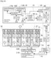
The first-stage module 24 and the second-stage module 26 have the same configuration. Each of the first-stage module 24 and the second-stage module 26 includes a phase shifter 28 and an amplifier 29. Phase shifter 28 changes the phase of the transmission signal by a command value. Phase shifter 28 changes the phase discretely with a pitch width of phase rotation determined by a number of bits determining resolution of the phase. For example, for a 5-bit phase shifter, the phase is rotated with the pitch width of 360°/25=11.25°. Phase shifter 28 may change the phase continuously. Phase shifter 28 of first-stage module 24 can change the phases of the plurality of element antennas 27 included in power transmission device 1 uniformly. Amplifier 29 amplifies the transmission signal.
In one power transmission device 1, element antennas 27 are arranged into a matrix form. Four power transmission devices 1 are arranged into the matrix form so as to be adjacent to each other. Thus, all element antennas 27 are arranged in the matrix form.
One power transmission device 1 is a phased array antenna including the plurality of element antennas 27 that can control the phase of the radiated radio wave. A set of four power transmission devices 1 can be considered as one phased array antenna 30. In the radio wave measurement system of the first embodiment, the beam shape of the radio wave radiated by phased array antenna 30 is measured. That is, phased array antenna 30 is a measurement target antenna whose beam shape is to be measured. One power transmission device 1 can be considered as a power transmitter, and an assembly of a plurality of power transmission devices 1 can be considered as a power transmission device. Power transmission device 1 corresponds to one group when the plurality of element antennas 27 are divided into a plurality of groups.
The operation is described, FIG. 4 is a flowchart illustrating a procedure for measuring a radiation pattern of the radio wave in the radio wave measurement system using the aerial moving body of the first embodiment. In step S01, a movement pattern of drone 3 is determined. It is assumed that the movement pattern is a pattern in which two-dimensional scan is performed on a cut surface perpendicular to the direction in which power transmission radio wave 2 is radiated. The radio wave is measured three-dimensionally by setting the cut surfaces at a plurality of positions having different distances from power transmission device 1.
In step S02, mobile communication system 12 sends flight command 75 to drone 3, and drone 3 is moved to an initial position in the movement pattern and caused to hover. In step S03, power transmission device 1 starts the power transmission, Steps S02 and S03 may be exchanged.
In step S04, detection data 73 including the amplitude and the phase of power transmission radio wave 2 received by monitor antenna 14 is measured according to measurement command 72 sent by mobile communication system 12. At the same time, positioning sensor 18 measures the position of drone 3. In step S05, positioned detection data 70 that is the pair of measured detection data 73 and measured position data 74 is stored in data storage device 17. In step S06, whether the measurement position at which detection data 73 is not measured yet exists is checked. When the measurement position at which detection data 73 is not measured yet exists (YES in S06), flight command 75 is sent to drone 3 by mobile communication system 12 to cause drone 3 to move and hover to the next measurement position in step S07. The processing returns to step S04.
When the measurement position at which detection data 73 is not measured yet does not exist (NO in S06), drone 3 is landed on the ground. Specifically, in step S08, flight command 75 is sent to drone 3 by mobile communication system 12, drone 3 is stopped on the ground, and drive motor 9 is stopped. In step S09, positioned detection data 70 is acquired from data storage device 17, and inputted to measurement system control device 21. Measurement system control device 21 converts position data 74 into relative position data 78 with respect to power transmission device 1 in step S10. In step S11, beam shape data 71 in which detection data 73 is correlated with relative position data 78 is generated. The operation of drone 3 in the flowchart of FIG. 4 is performed using the power stored in power storage device 19. The ground includes not only the ground but also structures, such as a building and a tower, installed on the ground.
The position of power transmission device 1 in the coordinate system, such as latitude, longitude, and altitude, is measured in advance by positioning sensor 18 and stored to calculate the position of drone 3 relative to power transmission device 1. The relative position data 78 is generated by subtracting the stored position of power transmission device 1 from position data 74 of drone 3. A positioning sensor may be provided also in power transmission device 1, and the relative position may be calculated by subtracting the measurement value of the positioning sensor.
The position of the power transmission device may be stored in the on-board control device, the data storage device, or another processing device, and the on-board control device or another processing device may convert the position data into relative position data. The on-board control device or another processing device may produce the radiated radio wave data including the detection data and the relative position data. In this case, the on-board control device or another processing device constitutes the radiated radio wave data generator. The case that the on-board control device produces the radiated radio wave data is described as follows. The previously-measured position of power transmission device 1 is stored in storage device of drone 3. The on-board control device converts position data 74 into relative position data 78, and generates beam shape data 71A in which detection data 73 is correlated with relative position data 78. Beam shape data 71A is also positioned detection data 70A in which detection data 73 and the relative position data 78 at the same time are combined. Positioned detection data 70A is also referred to as radio wave measurement data.
In the radio wave measurement system, power transmission radio wave 2 is radiated from power transmission device 1 to the sky. The radio wave measurement system measures beam shape data 71 of power transmission radio wave 2 above power transmission device 1 using drone 3 that is the aerial moving body. Consequently, beam shape data 71 of power transmission radio wave 2 of power transmission device 1 can be measured accurately while an influence of reflection is reduced.
In FIG. 4 , detection data 73 is measured while drone 3 is caused to hover. Alternatively, detection data 73 may be measured while drone 3 is moved. Flight command 75 is sent from mobile command device 4 to control how drone 3 is caused to fly or hover. Alternatively, drone 3 may operate according to a program stored in drone 3 to fly or hover autonomously. The program stored in drone 3 is a program to cause drone 3 to fly and hover on a determined flight route.
With reference to FIG. 5 , points different from FIG. 4 are described. In step S05A, measurement data 77 including the positioned detection data 70 is sent from on-board control device 16 to flight control device 5. Measurement data 77 is transmitted to measurement system control device 21 through mobile communication system 12 and mobile command device 4. In step S12, measurement system control device 21 stores positioned detection data 70 included in measurement data 77 in the non-volatile storage device of measurement system control device 21. Because of the existence of steps S05A and S12, step S09 of acquiring positioned detection data 70 from data storage device 17 of drone 3 is deleted from the flowchart. For this reason, the processing proceeds to step S10 after step S08 is performed.
Moreover, in the procedure shown in FIG. 5 , beam shape data 71 of power transmission device 1 can be measured accurately.
The radio wave measurement system can measure the beam shape of the radio wave radiated from not only the wireless power transmission device, but also an antenna for another application. The wireless power transmission device may be different from the one illustrated in the description. When the beam shape of the radio wave radiated from another wireless power transmission device or the antenna for another application is measured, the measurement target antenna means the antenna in which the beam shape is measured and the radio wave is radiated in a sky direction from the measurement target antenna. The aerial moving body such as the drone is caused to hover and move above the measurement target antenna that radiates the radio wave. The position of the aerial moving body is measured by a position measurer that is a positioning sensor such as a GPS. The aerial moving body is equipped with a measurement antenna that receives the radio wave and a detector that measures the received radio wave data including the amplitude and the phase of the radio wave received by the measurement antenna. The beam shape data is generated from the received radio wave data and measurement point data that is the position of the aerial moving body at the point of time when the received radio wave data is measured. In the beam shape data, the measurement point data is expressed as the position relative to the measurement target antenna.
Instead of the use of drone 3, a monitor antenna may be fixed at a predetermined position above power transmission device 1. However, because the radio wave is reflected or shielded by a structural member fixing the monitor antenna, there is a possibility of degrading the accuracy of the phase and the amplitude of the measured radio wave.
By performing the radio wave measurement in a place, such as the outdoors, where a radio wave environment is good, the beam shape of the measurement target antenna can be measured without being affected by multipath such as reflection on the ground. The term “not affected” means that the influence is sufficiently small. Moreover, a mobile communication system provided for controlling the drone is used for the purpose of the transmission of various data and commands. For this reason, it is not necessary to add new hardware to the drone for the purpose of the communication required to perform the beam shape measurement or the wireless power transmission. Consequently, a weight of the mounted device can be reduced, and the radio wave can be measured with low power consumption.
Measurement system control device 21, power transmission control device 22, on-board control device 16, and flight control device 5 are implemented by executing a dedicated program on a general-purpose computer or a dedicated computer. The general-purpose computer or the dedicated computer includes a memory and an arithmetic processor, such as a CPU (Central Processing Unit) that executes the program. The memory is a volatile or non-volatile memory and/or a hard disk. The memory stores the program operated by any one of measurement system control device 21, power transmission control device 22, on-board control device 16, and flight control device 5. The memory also stores data in the course of the processing and/or data of a processing result. The memory of on-board control device 16 may be shared with data storage device 17. Measurement system control device 21 and power transmission control device 22 may be constructed with one computer. On-board control device 16 and flight control device 5 may be constructed with one computer.
The above can be applied to other embodiments.
With reference to FIGS. 6 and 7 , a configuration of a power transmission system to an aerial moving body by a wireless power transmission device according to a second embodiment is described. FIG. 6 is a conceptual diagram illustrating the power transmission system to the aerial moving body by the wireless power transmission device of the second embodiment of the present disclosure. FIG. 7 is a block diagram illustrating the power transmission system to the aerial moving body by the wireless power transmission device of the second embodiment.
In FIGS. 6 and 7 , points different from FIGS. 1 and 2 are described. A drone 3A includes a pilot transmitter 32, a pilot transmission antenna 33, one or a plurality of power reception antennas 34 that receives power transmission radio wave 2, and a drone power supply system 8 A Pilot transmitter 32 generates a pilot signal 31 indicating a power transmission direction to a power transmission device 1A. Pilot transmission antenna 33 radiates pilot signal 31 toward power transmission device 1A. Drone power supply system 8A stores and uses the power that is obtained from the radio wave received by power reception antenna 34.
As in the first embodiment, monitor antenna 14 may receive power transmission radio wave 2, and detector 15 may measure the phase or the amplitude of the radio wave. When the radio wave is measured by monitor antenna 14 and detector 15, the power transmission system to the aerial moving body in the second embodiment may be recognized also as the radio wave measurement system. The data storage device and the on-board control device of the drone also have the same configuration as that of the first embodiment when the data storage device and the on-board control device constitute the radio wave measurement system.
In order to send pilot transmitter control command 79, measurement system control device 21A and a power transmission control device 22A can communicate with each other and send and receive data to perform a Rotating Element Electric Field Vector (REV) method before start of the power transmission. Although the reference numeral is not illustrated in FIG. 7 , a command to perform the REV method is sent from power transmission control device 22A to on-board control device 16A through measurement system control device 21A. The measured data of the received power is sent from on-board control device 16A to power transmission control device 22A. Power transmission control device 22A and on-hoard control device 16A may communicate with each other with no use of measurement system control device 21A.
With reference to FIG. 8 , the configuration of drone power supply system 8A is described. FIG. 8 is a block diagram illustrating the configuration of the power supply system of the aerial moving body that receives the power transmitted from the wireless power transmission device of the second embodiment. As compared to FIG. 3 , drone power supply system 8A in FIG. 8 includes a rectifier 35 and a rectification-side converter 36 additionally. Rectifier 35 rectifies the received signal generated from the radio wave received by power reception antenna 34 into a direct current. The rectification-side converter 36 changes the voltage of the DC power rectified by rectifier 35. Power storage device 19 stores the DC power outputted from the rectification-side converter 36.
The drone may include a plurality of power storage devices, and the power received by power reception antenna 34 during the flight may be stored in some of the power storage devices. At least one of the drone and the detector may use the power of the power storage device in which the power received during the flight is stored.
In the second embodiment, phased array antenna 30 functions as a power transmission antenna that can change an orientation direction in which the power is transmitted by the radio wave to be radiated. Drone 3A is an aerial moving body for a power transmission target. Arrival direction detection device 38 is a radiation direction determiner that determines the radiation direction that is the direction in which drone 3A exists when viewed from power transmission device 1A. Power transmission control device 22A is an orientation direction changer that directs the orientation direction of phased array antenna 30 toward the radiation direction.
The operation is described. FIG. 9 is a flowchart illustrating a power transmission procedure in the power transmission system to the aerial moving body by the wireless power transmission device of the second embodiment. In step S21, drone 3A is caused to hover at a predetermined position above power transmission device 1A.
In step S22, element antenna 27 corresponding to each of the plurality of second-stage modules 26 radiates the radio wave in each power transmission device 1A. The radio wave radiated by element antenna 27 is received by monitor antenna 14 of drone 3A. A phase difference between element electric field vectors generated at the positions of the monitor antennas 14 by the radio waves radiated by element antennas 27 is measured by the REV method. In the REV method, the phase of the radio wave radiated by one of second-stage modules 26 is changed to measure the change in the amplitude (electric field strength) of the electric field vector of the radio wave received by monitor antenna 14. Detection data 73 being the measured electric field strength is sent to power transmission control device 22 through mobile communication system 12 and measurement system control device 21. Power transmission control device 22 calculates the phase difference between the element electric field vector of the radio wave radiated by element antenna 27 corresponding to each second-stage module 26 and the electric field vector of the radio wave in which the radio waves radiated by all element antennas 27 are combined, from the change in the amplitude of the electric field vector sent by received detection data 73. The phase difference between the element electric field vectors generated by element antennas 27 is generated by a difference in path length inside power transmission device 1A, a difference in distance between each element antenna 27 and the monitor antenna 14, and the like.
In step S23, a phase offset value is set to phase shifter 28 included in each second-stage module 26 in consideration of the measured phase difference between multiple second-stage modules 26 included in each power transmission device 1A. The phase offset value is a value that is subtracted from a phase command value supplied externally. Phase shifter 28 changes the phase by an amount obtained by subtracting the phase offset value from the phase command value. Thus, the amount of change in phase of the transmission signal outputted by phase shifter 28 actually is a value obtained by subtracting the phase offset value from the phase command value. When the same phase command value is given to each second-stage module 26, each second-stage module 26 can radiate the radio wave having the same phase by subtracting the phase offset value from the phase command value.
In step S24, the phase difference between the electric field vectors radiated by each of the plurality of power transmission devices 1A and received and generated by the monitor antenna 14 is measured by the REV method while the phase of the first-stage module 24 of each power transmission device 1A is changed. The phase difference between the electric field vectors generated by power transmission devices 1A due to the difference in the path length to first-stage module 24 of each power transmission device 1A or the difference in the distance from each power transmission device 1A to monitor antenna 14 is measured in the REV method. In step S25, the phase offset value of phase shifter 28 included in first-stage module 24 of each power transmission device 1A is set in consideration of the measured phase difference between the radio waves radiated by power transmission devices 1A.
In the pieces of processing in S21 to S25, the phase offset value due to the difference in the path length inside each power transmission device 1A is measured in advance in each first-stage module 24 or second-stage module 26, and the phase command value of each phase shifter 28 is determined in consideration of the previously-measured phase offset value. For this reason, the radio wave radiated from each element antenna 27 can be set to the value in which the phase reference is matched. The pieces of processing in S21 to S25 are performed before power transmission device 1A is used for the first time. When the element module that is first-stage module 24 or second-stage module 26 is replaced, the phase offset value of the replaced element module is obtained.
In step S26, pilot transmission antenna 33 of drone 3A transmits pilot signal 31. In step S27, pilot reception antenna 37 of power transmission device 1A receives pilot signal 31. In step S28, arrival direction detection device 38 determines arrival direction data 80 of pilot signal 31. In step S29, power transmission control device 22A calculates the command values of the phase and amplitude for each of the element modules of power transmission device 1A such that power transmission radio wave 2 can be transmitted while the direction toward which the arrival direction indicated by arrival direction data 80 is set to the radiation direction. Power transmission control signal 76 is the command values of the phase and amplitude for each element module. Element antenna 27 of each second-stage module 26 radiates the radio wave having the adjusted phase. This allows the radio wave radiated in the radiation direction to be strengthened. The beam shape can be made more desirable by adjusting the amplitude of the radio wave radiated by each element antenna 27. Consequently, power transmission device 1A can efficiently transmit the power in the radiation direction.
In step S30, first-stage module 24 and each second-stage module 26 of each power transmission device 1A generate the transmission signals in which the phases and amplitudes are adjusted according to power transmission control signal 76, and radiate the transmission signals from corresponding element antennas 27 as power transmission radio wave 2.
In parallel to steps S26 to S30, in step S31, power transmission radio wave 2 is received by power reception antenna 34 of drone 3A, and the DC power rectified and converted by rectifier 35 and rectification-side converter 36 is stored in power storage device 19.
The pieces of processing in S26 to S30 and S31 are performed periodically in a determined period. After performing steps S30 and S31, the processing returns before S26 and S31. A length of one period is determined such that the difference between the previously-calculated arrival direction and the current arrival direction falls within an acceptable range when drone 3 moves at the assumed maximum movement speed.
Whether the beam shape formed actually by power transmission radio wave 2 radiated in step S30 of FIG. 9 becomes the assumed beam shape can be verified. For this reason, the beam shape of the radio wave beam that is radiated while the phase command value and the amplitude command value for each element antenna 27 are fixed can be measured using, for example, the radio wave measurement system in FIGS. 1 and 2 . In this case, the power transmission system to the aerial moving body by the wireless power transmission device of the second embodiment is also a radio wave measurement system using the aerial moving body.
As a radio wave measurement system, instead of using the drone 3A, the monitor antenna may be fixed at a predetermined position above the power transmission device 1A. However, because the radio wave is reflected or shielded by a structural member fixing the monitor antenna, there is a possibility of degrading the accuracy of the phase and the amplitude of the measured radio wave.
The influence of multipath such as ground reflection is reduced by performing the control of the power transmission radio wave and the wireless power transmission to the aerial moving body using the radio waves at a place having a good radio wave environment such as outdoors. For this reason, the wireless power transmission by the radio wave can be performed with higher accuracy than the conventional technique. Because the transmission of various data and commands uses the mobile communication system provided for controlling the drone, it is not necessary to add new hardware to the drone for the purpose of the communication necessary for performing the wireless power transmission. Consequently, the weight of the mounted device can be reduced, and the wireless power transmission to the drone can be performed with low power consumption.
Instead of the phased array antenna, the power may be transmitted to the aerial moving body using a wireless power transmission device including a power transmission antenna that changes the orientation direction mechanically. The direction in which the aerial moving body exists may be sent to the wireless power transmission device by means other than the pilot signal. Any wireless power transmission device can radiate the radio wave in the direction in which the aerial moving body exists with higher accuracy than the conventional technique and improve the efficiency of the wireless power transmission as long as the wireless power transmission device includes the power transmission antenna that can change the orientation direction in which the power is transmitted by the radiated radio wave, the radiation direction determiner that determines the radiation direction that is the direction in which the aerial moving body of the power transmission target exists, the orientation direction changer that directs the orientation direction of the power transmission antenna in the radiation direction, and a transmission signal generator that generates the transmission signal transmitted as the radio wave from the power transmission antenna. Sometimes arrival direction detection device 38 that is the radiation direction determiner is installed in the position apart from power transmission device 1A, such arrival direction detection device 38 is included in the wireless power transmission device.
By performing the REV method using the aerial moving body such as the drone, the REV method can be performed in a situation where the power is transmitted actually to the aerial moving body. For this reason, the REV method can accurately be performed, and the radio wave can accurately be radiated in the direction in which the aerial moving body exists when the power is transmitted to the aerial moving body. That is, the radio wave can be radiated in the direction in which the aerial moving body exists with higher accuracy than the conventional technique, and the efficiency of the wireless power transmission can be improved higher than the conventional technique.
When the wireless power transmission device is not used as the radio wave measurement system, measurement system control device 21A can be omitted. When measurement system control device 21A does not exist, power transmission control device 22A sends and receives the command to perform the REV method and the measured data of the received power through mobile command device 4A and mobile communication system 12. Flows of the command to perform the REV method and the measured data of the received power are not illustrated in FIG. 7 .
When the REV method is performed, an antenna fixed to the ground may be used instead of the measurement antenna mounted on the drone. In this case, the drone does not have the function of performing the REV method. The drone may not include the measurement antenna, but the detector connected to the power reception antenna may measure the electric field strength of the radio wave received by the power reception antenna. That is, the power reception antenna may be used as the measurement antenna.
The above can be applied to other embodiments.
A third embodiment is the case that the second embodiment is changed such that the power transmission device transmits the power toward the aerial moving body by transmitting the position data of the aerial moving body to the power transmission device instead of the pilot signal. With reference to FIG. 10 , a configuration of a power transmission system to an aerial moving body by a wireless power transmission device of the third embodiment of the present disclosure is described. FIG. 10 is a configuration diagram illustrating the power transmission system to the aerial moving body by the wireless power transmission device of the third embodiment of the present disclosure.
In FIG. 10 , points different from FIG. 7 of the second embodiment are described. Power transmission device 1 is the same as that of the first embodiment. Power transmission device 1 does not include pilot reception antenna 37. Arrival direction detection device 38 does not exist. A drone 3B does not include pilot transmitter 31 and pilot transmission antenna 33. Drone 3B includes positioning sensor 18. Position data 74 measured by positioning sensor 18 is sent to a measurement system control device 21B through an on-board control device 16B, a flight control device 5B, mobile communication system 12 and mobile command device 44. Position data 74 is stored also in data storage device 17B. Positioning sensor 18 may be connected to a flight control device 5B. In this case, position data 74 is sent to power transmission control device 22B though flight control device 5B, mobile communication system 12, a mobile command device 4B, and measurement system control device 21B.
The operation is described. FIG. 11 is a flowchart illustrating a power transmission procedure in the power transmission system to the aerial moving body by the wireless power transmission device of the third embodiment. In FIG. 11 , points different from FIG. 9 of the second embodiment are described. Steps S26 to S28 are changed to steps S32 to S35. In step S32, positioning sensor 18 measures the three-dimensional position where drone 3B exists. In step S33, measured position data 74 is sent to mobile command device 4B by mobile communication system 12. In step S34, power transmission control device 22B acquires position data 74 from mobile command device 4B through measurement system control device 21B. In step S35, power transmission control device 22B converts position data 74 into a position relative to power transmission device 1, and obtains the radiation direction. In step S29A, power transmission control device 22B calculates power transmission control signal 76 instructing the phase and the amplitude for each of first-stage module 24 and second-stage module 26 of each power transmission device 1A. Power transmission control signal 76 is calculated such that power transmission device 1 can transmit power transmission radio wave 2 toward the radiation direction determined from the position of drone 3B relative to power transmission device 1.
The above can be applied to other embodiments.
A fourth embodiment is the case that the drone that is the aerial moving body measures the beam shape data of the power transmission radio wave radiated by the wireless power transmission device while being supplied with the power from the wireless power transmission device. Because the drone receives the supply of the power from the wireless power transmission device, a radio wave measurement system using an aerial moving body of the fourth embodiment is also the power transmission system to the aerial moving body by the wireless power transmission device. With reference to FIG. 12 , a configuration of the radio wave measurement system using the aerial moving body of the fourth embodiment of the present disclosure and the power transmission system to the aerial moving body by the wireless power transmission device of the fourth embodiment is described. FIG. 12 is a configuration diagram illustrating the radio wave measurement system using the aerial moving body of the fourth embodiment of the present disclosure and the power transmission system to the aerial moving body by the wireless power transmission device of the fourth embodiment.
In FIG. 12 , points different from FIG. 2 of the first embodiment are described. A drone 3C is obtained by changing drone 3 of the first embodiment so as to include power reception antenna 34 and drone power supply system 8A similar to those of the second embodiment. Power transmission device 1 is the same as that of the first embodiment.
The operation is described. FIG. 13 is a flowchart illustrating a procedure for measuring the radiation pattern of the radio wave in the radio wave measurement system using the aerial moving body of the fourth embodiment and the power transmission system to the aerial moving body by the wireless power transmission device of the fourth embodiment. In FIG. 13 , points different from FIG. 4 of the first embodiment are described. In parallel to steps S04 to S07, in steps S13 and S14, power transmission radio wave 2 is received by power reception antenna 34, and the power obtained by rectifying received power transmission radio wave 2 using rectifier 35 is stored in power storage device 19. Step S13 operates in parallel to steps S04 and S05. Step S14 operates in parallel to step S07.
Because the beam shape of power transmission device 1 is measured, unlike the second embodiment and the like, power transmission control device 22A does not change the beam direction according to the position where drone 3C exists.
A fifth embodiment is the case that the first embodiment is changed such that a communication system that communicates a measurement command and detection data for the radio wave measurement between the on-board control device and the measurement system control device is provided in addition to the mobile communication system. With reference to FIG. 14 , a configuration of a radio wave measurement system using an aerial moving body according to the fifth embodiment of the present disclosure is described. FIG. 14 is a configuration diagram illustrating the radio wave measurement system using the aerial moving body of the fifth embodiment of the present disclosure. Instead of the first embodiment, the radio wave measurement system of the fourth embodiment or the radio wave measurement system having another configuration and the power transmission system to the aerial moving body may be changed.
A power transmission communication system 39 and a pilot communication system 40 are added in a drone 3D of the fifth embodiment. A measurement system control device 21C sends measurement command 72 to a mounted device 13D mounted on drone 3D, using power transmission communication system 39. Mounted device 13D sends detection data 73 to measurement system control device 21C, using pilot communication system 40. Positioning sensor 18 sends position data 74 to an on-board control device 16D. A data storage device 17D stores data indicating whether or not power transmission communication system 39 and pilot communication system 40 are used.
Power transmission communication system 39 includes a first-stage module 24A, a second-stage module 26A, element antenna 27 of a power transmission device 1B, and monitor antenna 14 and a detector 15A that are mounted on drone 3D. A pulse modulation switch 41 that switches radiation and non-radiation of a power transmission radio wave 2A according to a signal sequence of 0 or 1 representing measurement command 72 is added to first-stage module 24A and second-stage module 26A. That is, measurement command 72 is sent by pulse modulation of power transmission radio wave 2A using detection data 73. Detector 15A demodulates measurement command 72 from the reception or non-reception of received power transmission radio wave 2A. Measurement command 72 may be modulated and demodulated by not the pulse modulation but amplitude modulation or phase modulation such as BPSK (Binary Phase Shift Keying).
Measurement system control device 21C includes a communication system changeover switch 42. Communication system changeover switch 42 switches which one of a mobile command device 4C and a power transmission control device 22 C measurement command 72 is sent to. That is, communication system changeover switch 42 switches which one of mobile communication system 12 and power transmission communication system 39 is used. A transmission destination of measurement command 72 may be switched by software.
Using software, on-hoard control device 16D switches whether detection data 73 is sent to flight control device 5 or pulse modulation switch 43 is controlled by detection data 73. Consequently, which one of pilot communication system 40 and mobile communication system 12 sends detection data 73 is switched.
The operation is described, FIG. 15 is a flowchart illustrating a procedure for measuring the radiation pattern of the radio wave in the radio wave measurement system using the aerial moving body of the fifth embodiment. In FIG. 15 , points different from FIG. 5 of the first embodiment are described. At this point, a communication system that communicates measurement command 72 is referred to as a command communication system. A communication system that communicates measurement data 77 is referred to as a data communication system. Step S15 is added between steps S03 and S04A, in step S15, which one of mobile communication system 12 and power transmission communication system 39 is determined as the command communication system. In step S04A, detection data 73 including the amplitude and the phase of power transmission radio wave 2 received by monitor antenna 14 is measured according to measurement command 72 communicated by the command communication system determined in step S15. At the same time, the position of drone 3D is measured. Step S16 is added between steps S04A and S05B. In step S16, which one of mobile communication system 12 and pilot communication system 40 is determined as the data communication system. In step S05B, positioned detection data 70 is sent from on-board control device 16D to measurement system control device 21C through the data communication system determined in step S16.
The command communication system may be determined not every time measurement command 72 is communicated, but every several times. Flight command 75 may be communicated by power transmission communication system 39. Data communication system may be determined not every time measurement data 77 is communicated, but every several times. When communication with mobile communication system 12 is attempted but communication cannot be performed with mobile communication system 12, power transmission communication system 39 may be determined as the command communication system or pilot communication system 40 may be determined as the data communication system.
By providing power transmission communication system 39 and pilot communication system 40, the necessary data can be communicated at a necessary speed when a communication load on mobile communication system 12 is increased to slow the communication. Alternatively, power transmission communication system 39 and pilot communication system 40 can be used when mobile communication system 12 is out of order. Thus, power transmission communication system 39 and pilot communication system 40 contribute to stable operation of the radio wave measurement system greatly. The communication can be performed by the pulse modulation (on and off control of the transmission), the amplitude modulation, and the phase modulation of power transmission radio wave 2 and pilot signal 31 using a simple device. Consequently, the control of the power transmission radio wave and exchange of the data can be performed without adding large hardware and without increasing the load and the power consumption of mobile communication system 12.
A sixth embodiment is the case that the second embodiment that is also the radio wave measurement system is changed such that a measurement communication system that communicates the measurement command and the detection data between the on-board control device and the measurement system control device is provided. In the sixth embodiment, the mobile communication system is not used in order to communicate the measurement command and the detection data between the on-board control device and the measurement system control device. The sixth embodiment is an embodiment of a radio wave measurement system using an aerial moving body and a power transmission system to an aerial moving body by a wireless power transmission device. With reference to FIG. 16 , a configuration of the radio wave measurement system using the aerial moving body of the sixth embodiment and the power transmission system to the aerial moving body by the wireless power transmission device of the sixth embodiment is described. FIG. 16 is a configuration diagram illustrating the radio wave measurement system using the aerial moving body of the sixth embodiment and the power transmission system to the aerial moving body by the wireless power transmission device of the sixth embodiment of the present disclosure.
In the configuration of FIG. 16 , a measurement communication system 45 is added to the configuration of the second embodiment in FIG. 7 . Measurement communication system 45 includes an on-board communication device 46 and an on-board communication antenna 47 that are mounted on a drone 3E and a ground communication antenna 48 and a ground communication device 49 that are installed on the ground. Measurement command 72 from a measurement system control device 21D is sent to drone 3E by measurement communication system 45. Measurement data 77 measured by drone 3E is sent to measurement system control device 21D by measurement communication system 45. Measurement communication system 45 is a communication system other than mobile communication system 12. A data storage device 17E differs from data storage device 17A of the second embodiment in that data storage device 17E also stores data that is necessary for the radio wave measurement system, such as the measurement data 77.
The communication is not allowed between an on-board control device 16E and a flight control device 5C. Only a mounted device 13E is mounted on drone 3E, and no interface with the instrument included in drone 3E exists. Positioning sensor 18 is connected to on-board control device 16E such that position data 74 can be used in the power transmission system.
A mobile command device 4D sends flight command 75 using mobile communication system 12, and controls the flight of drone 3E.
With reference to FIG. 17 , a drone power supply system 8B is described. FIG. 17 is a block diagram illustrating a configuration of the radio wave measurement system using the aerial moving body of the sixth embodiment and the power supply system of the aerial moving body that receives the power transmitted from the wireless power transmission device of the sixth embodiment. The difference between FIGS. 17 and 8 is that a measurement system power supply line 50 is added. Measurement system power supply line 50 is connected to power storage device 19 mounted on drone 3E. Rectification-side converter 36, load-side converter 20 b, and load-side converter 20 c are connected to power storage device 19 through measurement system power supply line 50. By providing measurement system power supply line 50, the connection point of the power supply system between drone 3E and mounted device 13E can be made only at one place of measurement system power supply line 50. The rectification-side converter may not be provided, and the configuration of the load-side converter may be changed.
The power transmission system to the aerial moving body of the sixth embodiment operates similarly to the second embodiment. The point different from power transmission system of the second embodiment is that the command and data that are used to perform the REV method are communicated using not mobile communication system 12 but measurement communication system 45. The sixth embodiment as the radio wave measurement system operates similarly to the radio wave measurement system of the first embodiment. The sixth embodiment differs from the first embodiment in that measurement communication system 45 is used.
Because transmission and reception of the data between the mounted device and the drone is not necessary, the radio wave measurement system can be constructed without modifying a commercially available drone. The mounted device can be mounted on another drone easily. That the mobile communication system is not used in order to communicate the command for radio wave measurement and the measured data can be applied to other embodiments.
A seventh embodiment is the case that the sixth embodiment is changed such that a power transmission communication system and a pilot communication system similar to the fifth embodiment are added. With reference to FIG. 18 , a configuration of a radio wave measurement system using an aerial moving body of the seventh embodiment and a power transmission system to an aerial moving body by a wireless power transmission device of the seventh embodiment is described. FIG. 18 is a configuration diagram illustrating the radio wave measurement system using the aerial moving body of the seventh embodiment of the present disclosure and the power transmission system to the aerial moving body by the wireless power transmission device of the seventh embodiment.
The configuration in FIG. 18 is substantially similar to the configuration in FIG. 14 of the fifth embodiment. The configuration in FIG. 18 is different from the configuration in FIG. 14 in the following points. A communication system changeover switch 42A provided in a measurement system control device 21E switches which one of ground communication device 49 and a power transmission control device 22D sends measurement command 72. That is, communication system changeover switch 42A switches which one of measurement communication system 45 and power transmission communication system 39 is used. An on-board control device 16F switches by software whether detection data 73 is sent to on-board communication device 46 or pulse modulation switch 43 is controlled using detection data 73. Consequently, on-board control device 16F switches which one of measurement communication system 45 and pilot communication system 40 sends detection data 73.
The power transmission system to the aerial moving body of the seventh embodiment operates similarly to the second embodiment. The seventh embodiment differs from the second embodiment in that measurement communication system 45 is used instead of mobile communication system 12. The seventh embodiment as the radio wave measurement system operates similarly to the radio wave measurement system of the fifth embodiment. The seventh embodiment differs from the fifth embodiment in that measurement communication system 45 is used.
Because transmission and reception of the data between the mounted device and the drone is not necessary, the radio wave measurement system and/or the power transmission system to the aerial moving body can be constructed without modifying a commercially available drone. Power transmission communication system 39 and pilot communication system 40 can be used when measurement communication system 45 is out of order. Thus, power transmission communication system 39 and pilot communication system 40 contribute to stable operation of the radio wave measurement system and/or the power transmission system greatly.
The mobile communication system may be used for the communication between the on-board control device and the measurement system control device. In this case, because a triple communication system exists between the on-board control device and the measurement system control device, reliability of the communication system is further improved. The same applies to the sixth embodiment.
An eighth embodiment is the case that the fifth embodiment is changed such that the position of the aerial moving body is measured by the positioning device installed on the ground. With reference to FIGS. 19 and 20 , a configuration of a radio wave measurement system using an aerial moving body according to the eighth embodiment is described. FIG. 19 is a conceptual diagram illustrating the radio wave measurement system using the aerial moving body of the eighth embodiment of the present disclosure. FIG. 20 is a block diagram illustrating the radio wave measurement system using the aerial moving body of the eighth embodiment. Other embodiments can be changed such that the position of the aerial moving body is measured from the ground.
In FIG. 20 , points different from FIG. 14 of the fifth embodiment are described. A drone 3G does not include positioning sensor 18. A laser positioning device 51 that measures the position of drone 3G is installed in the vicinity of power transmission device 1B. Position data 74 representing the position of drone 3G and measured by laser positioning device 51 is inputted to a measurement system control device 21F in a fixed period during the radio wave measurement. A data storage device 17G does not store position data 74, and stores the data indicating whether or not power transmission communication system 39 and pilot communication system 40 are used.
The operation is described. With reference to FIG. 21 , the operation of the radio wave measurement system is described. FIG. 21 is a flowchart illustrating a procedure for measuring the radiation pattern of the radio wave in the radio wave measurement system using the aerial moving body of the eighth embodiment.
In FIG. 21 , points different from FIG. 15 of the fifth embodiment are described. In step S04B, drone 3G does not measure position data 74. In step S05C, measurement data 77 including measured detection data 73 is sent from an on-board control device 16G to flight control device 5, and sent to measurement system control device 21F through mobile communication system 12 and mobile command device 4C. In step S17, measurement system control device 21F combines detection data 73 included in received measurement data 77 and latest position data 74 to produce positioned detection data 70.
As in the fifth embodiment, in the radio wave measurement system, transmission radio wave 2 is radiated upward from power transmission device 1, and beam shape data 71 of power transmission radio wave 2 is measured above power transmission device 1 using drone 3G that is the aerial moving body. Consequently, beam shape data 71 of power transmission radio wave 2 of power transmission device 1 can accurately be measured while an influence of reflection is reduced.
Because drone 3G does not include the positioning sensor, drone 3G does not use the power in order to measure the own position. Because position data 74 is not sent from drone 3G, it is not necessary to consume the power required to send position data 74. Thus, drone 3G can fly for a longer time than the case of the fifth embodiment.
In the present disclosure, a free combination of the embodiments or a modification or omission of each embodiment can be made without departing from the scope of the present disclosure.
-
- 1, 1A: power transmission device (wireless power transmission device)
- 2: power transmission radio wave (radio wave)
- 3, 3A, 3B, 3C, 3D, 3E, 3F, 3G: drone (aerial moving body)
- 4, 4A, 4B, 4C, 4D: mobile command device
- 5, 5A, 5B, 5C: flight control device
- 6: on-board communication antenna
- 7: wireless modem
- 8, 8A, 8B: drone power supply system
- 9: drive motor
- 10: wireless modem
- 11: communication antenna.
- 12: mobile communication system
- 13, 13A, 13B, 13C, 13D, 13E, 13F, 13G: mounted device
- 14: monitor antenna (measurement antenna)
- 15, 15A: detector (radio wave measurer)
- 16, 16A, 16B, 16D, 16E, 16F, 16G: on-board control device
- 17, 17A, 17B, 17D, 17E, 17G: data storage device (storage device)
- 18: positioning sensor (position measurer)
- 19: power storage device
- 20 a, 20 b, 20 c: load-side converter
- 21, 21D, 21E, 21F, 21G: measurement system control device (radiated radio wave data generator)
- 21A, 21B: measurement system control device
- 22: power transmission control device
- 22A, 22B, 22C, 22D: power transmission control device (radiation direction determiner, orientation direction changer)
- 23: transmission signal generator
- 24, 24A: first-stage module (element module)
- 25: distribution circuit
- 26, 26A: second-stage module (element module)
- 27: element antenna
- 28: phase shifter
- 29: amplifier
- 30: phased array antenna (measurement target antenna, power transmission antenna)
- 31: pilot signal
- 32: pilot transmitter (direction signal transmitter, direction signal transmission reception system)
- 33: pilot transmission antenna (direction signal transmitter, direction signal transmission reception system)
- 34: power reception antenna
- 35: rectifier
- 36: rectification-side converter
- 37: pilot reception antenna (direction signal receiver, direction signal transmission reception system)
- 38: arrival direction detection device (radiation direction determiner)
- 39: power transmission communication system
- 40: pilot communication system
- 41: pulse modulation switch
- 42, 42A: communication system changeover switch
- 43: pulse modulation switch
- 44: detector
- 45: measurement communication system
- 46: on-board communication device
- 47: on-board communication antenna
- 48: ground communication antenna
- 49: ground communication device
- 50: measurement system power supply line
- 51: laser positioning device
- 70, 70A: positioned detection data (radio wave measurement data)
- 71, 71A: beam shape data (radiated radio wave data)
- 72: measurement command
- 73: detection data (received radio wave data)
- 74: position data (measurement point data)
- 75: flight command
- 76: power transmission control signal
- 77: measurement data
- 78: relative position data (radio wave source relative position data)
- 79: pilot transmitter control command
- 80: arrival direction data
- 81: radiation direction data
- 82: laser beam
- 83: reflected laser beam
Claims (20)
1. A wireless power transmission device, comprising:
a power transmission antenna to transmit power by radiating a radio wave and being capable of changing an orientation direction;
a radiation direction determiner to determine a radiation direction, the radiation direction being a direction in which an aerial moving body as a power transmission target exists;
an orientation direction changer to direct the orientation direction of the power transmission antenna toward the radiation direction; and
a transmission signal generator to generate a transmission signal transmitted as the radio wave from the power transmission antenna, wherein
the power transmission antenna is a phased array antenna including:
a plurality of element antennas to radiate the radio wave; and
a plurality of element modules, each of the plurality of element modules including a phase shifter to change a phase of the transmission signal and an amplifier to amplify the transmission signal,
the orientation direction changer controls a phase shift amount of the phase shifter,
a phase offset value for the phase shifter included in each of the plurality of element modules is calculated by performing a REV (rotating element electric field vector) method using a hovering aerial moving body hovering above the power transmission antenna,
the hovering aerial moving body is the aerial moving body or an aerial moving body different from the aerial moving body,
the hovering aerial moving body mounts a measurement antenna to receive the radio wave radiated by the power transmission antenna while performing the REV method and a radio wave measurer to measure received radio wave data including an amplitude of the radio wave received by the measurement antenna,
the phase offset value is calculated from the received radio wave data sent from the hovering aerial moving body, and
the phase shifter changes the phase by an amount obtained by subtracting the phase offset value from the phase shift amount.
2. The wireless power transmission device according to claim 1 , wherein
the power transmission antenna includes a plurality of power transmitters, each of the plurality of power transmitters includes:
a plurality of element antennas;
a plurality of second-stage modules, each of the plurality of second-stage modules being the element module; and
a first-stage module being the element module to change the phases of the transmission signals uniformly, each of the transmission signals being inputted to each of the plurality of element antennas, and
the phase offset value for the phase shifter included in each of the plurality of second-stage modules is determined so that the element antenna corresponding to the second-stage module radiates the radio wave having the same phase when the same phase command value is given to each of the plurality of second-stage modules.
3. The wireless power transmission device according to claim 2 , wherein the phase offset value for the phase shifter included in the first-stage module is determined based on a phase difference measured among the radio waves, each of the radio waves being radiated by each of the plurality of power transmitters.
4. The wireless power transmission device according to claim 1 , wherein
the power transmission antenna includes a plurality of power transmitters, each of the plurality of power transmitters includes:
a plurality of element antennas;
a plurality of second-stage modules, each of the plurality of second-stage modules being the element module; and
a first-stage module being the element module to change the phases of the transmission signals uniformly, each of the transmission signals being inputted to each of the plurality of element antennas, and
the phase offset value for the phase shifter included in the first-stage module is determined based on a phase difference measured among the radio waves, each of the radio waves being radiated by each of the plurality of power transmitters.
5. The wireless power transmission device according to claim 1 , further comprising a position measurer to measure a mobile position, the mobile position being a position of the aerial moving body being the power transmission target, wherein
the radiation direction determiner determines a direction directed toward the mobile position as the radiation direction.
6. The wireless power transmission device according to claim 5 , wherein the position measurer is installed on a ground.
7. A power transmission system to an aerial moving body comprising:
the wireless power transmission device according to claim 1 ;
the hovering aerial moving body to hover above the power transmission antenna;
the measurement antenna mounted on the hovering aerial moving body; and
the radio wave measurer mounted on the hovering aerial moving body, wherein
a radio wave measurer mounted on the hovering aerial moving body to measure received radio wave data including an amplitude of the radio wave, wherein
a command to perform the REV method is transmitted by the radio wave.
8. A power transmission system to an aerial moving body comprising:
the wireless power transmission device according to claim 2 ;
the hovering aerial moving body to hover above the power transmission antenna;
the measurement antenna mounted on the hovering aerial moving body; and
the radio wave measurer mounted on the hovering aerial moving body, wherein
a radio wave measurer mounted on the hovering aerial moving body to measure received radio wave data including an amplitude of the radio wave, wherein
a command to perform the REV method is transmitted by the radio wave.
9. A power transmission system to an aerial moving body comprising:
the wireless power transmission device according to claim 4 ;
the hovering aerial moving body to hover above the power transmission antenna;
the measurement antenna mounted on the hovering aerial moving body; and
the radio wave measurer mounted on the hovering aerial moving body, wherein
a radio wave measurer mounted on the hovering aerial moving body to measure received radio wave data including an amplitude of the radio wave, wherein
a command to perform the REV method is transmitted by the radio wave.
10. A power transmission system to an aerial moving body comprising:
the wireless power transmission device according to claim 1 ;
the hovering aerial moving body to hover above the power transmission antenna;
the measurement antenna mounted on the hovering aerial moving body;
the radio wave measurer mounted on the hovering aerial moving body;
a direction signal transmission reception system to transmit and receive a direction signal emitted by the aerial moving body to indicate an existence direction being a direction in which the aerial moving body exists when viewed from the power transmission antenna; and
a measurement communication system being a communication system different from a mobile communication system for controlling the aerial moving body, wherein
one of the direction signal transmission reception system and the measurement communication system is selected to send the received radio wave data from the aerial moving body.
11. A power transmission system to an aerial moving body comprising:
the wireless power transmission device according to claim 2 ;
the hovering aerial moving body to hover above the power transmission antenna;
the measurement antenna mounted on the hovering aerial moving body;
the radio wave measurer mounted on the hovering aerial moving body;
a direction signal transmission reception system to transmit and receive a direction signal emitted by the aerial moving body to indicate an existence direction being a direction in which the aerial moving body exists when viewed from the power transmission antenna; and
a measurement communication system being a communication system different from a mobile communication system for controlling the aerial moving body, wherein
one of the direction signal transmission reception system and the measurement communication system is selected to send the received radio wave data from the aerial moving body.
12. A power transmission system to an aerial moving body comprising:
the wireless power transmission device according to claim 4 ;
the hovering aerial moving body to hover above the power transmission antenna;
the measurement antenna mounted on the hovering aerial moving body;
the radio wave measurer mounted on the hovering aerial moving body;
a direction signal transmission reception system to transmit and receive a direction signal emitted by the aerial moving body to indicate an existence direction being a direction in which the aerial moving body exists when viewed from the power transmission antenna; and
a measurement communication system being a communication system different from a mobile communication system for controlling the aerial moving body, wherein
one of the direction signal transmission reception system and the measurement communication system is selected to send the received radio wave data from the aerial moving body.
13. A power transmission system to an aerial moving body comprising:
the wireless power transmission device according to claim 1 ;
the hovering aerial moving body configured to hover above the power transmission antenna;
the measurement antenna mounted on the hovering aerial moving body;
the radio wave measurer mounted on the hovering aerial moving body;
a direction signal transmission reception system to transmit and receive a direction signal emitted by the aerial moving body to indicate an existence direction being a direction in which the aerial moving body exists when viewed from the power transmission antenna; and
a measurement communication system being a communication system different from a mobile communication system for controlling the aerial moving body, wherein
one of the direction signal transmission reception system, the mobile communication system, and the measurement communication system is selected to send the received radio wave data from the aerial moving body.
14. A power transmission system to an aerial moving body comprising:
the wireless power transmission device according to claim 2 ;
the hovering aerial moving body configured to hover above the power transmission antenna;
the measurement antenna mounted on the hovering aerial moving body;
the radio wave measurer mounted on the hovering aerial moving body;
a direction signal transmission reception system to transmit and receive a direction signal emitted by the aerial moving body to indicate an existence direction being a direction in which the aerial moving body exists when viewed from the power transmission antenna; and
a measurement communication system being a communication system different from a mobile communication system for controlling the aerial moving body, wherein
one of the direction signal transmission reception system, the mobile communication system, and the measurement communication system is selected to send the received radio wave data from the aerial moving body.
15. A power transmission system to an aerial moving body comprising:
the wireless power transmission device according to claim 4 ;
the hovering aerial moving body configured to hover above the power transmission antenna;
the measurement antenna mounted on the hovering aerial moving body;
the radio wave measurer mounted on the hovering aerial moving body;
a direction signal transmission reception system to transmit and receive a direction signal emitted by the aerial moving body to indicate an existence direction being a direction in which the aerial moving body exists when viewed from the power transmission antenna; and
a measurement communication system being a communication system different from a mobile communication system for controlling the aerial moving body, wherein
one of the direction signal transmission reception system, the mobile communication system, and the measurement communication system is selected to send the received radio wave data from the aerial moving body.
16. A power transmission system to an aerial moving body comprising:
the wireless power transmission device according to claim 1 ;
the hovering aerial moving body configured to hover above the power transmission antenna;
the measurement antenna mounted on the hovering aerial moving body;
the radio wave measurer mounted on the hovering aerial moving body; and
a direction signal transmission reception system to transmit and receive a direction signal emitted by the aerial moving body to indicate an existence direction being a direction in which the aerial moving body exists when viewed from the power transmission antenna, wherein
one of a mobile communication system for controlling the aerial moving body and the direction signal transmission reception system is selected to send the received radio wave data from the aerial moving body.
17. A power transmission system to an aerial moving body comprising:
the wireless power transmission device according to claim 2 ;
the hovering aerial moving body configured to hover above the power transmission antenna;
the measurement antenna mounted on the hovering aerial moving body;
the radio wave measurer mounted on the hovering aerial moving body; and
a direction signal transmission reception system to transmit and receive a direction signal emitted by the aerial moving body to indicate an existence direction being a direction in which the aerial moving body exists when viewed from the power transmission antenna, wherein
one of a mobile communication system for controlling the aerial moving body and the direction signal transmission reception system is selected to send the received radio wave data from the aerial moving body.
18. A power transmission system to an aerial moving body comprising:
the wireless power transmission device according to claim 4 ;
the hovering aerial moving body configured to hover above the power transmission antenna;
the measurement antenna mounted on the hovering aerial moving body;
the radio wave measurer mounted on the hovering aerial moving body; and
a direction signal transmission reception system to transmit and receive a direction signal emitted by the aerial moving body to indicate an existence direction being a direction in which the aerial moving body exists when viewed from the power transmission antenna, wherein
one of a mobile communication system for controlling the aerial moving body and the direction signal transmission reception system is selected to send the received radio wave data from the aerial moving body.
19. The power transmission system to an aerial moving body according to claim 10 , wherein a command to perform the REV method is transmitted by the radio wave.
20. The power transmission system to an aerial moving body according to claim 13 , wherein a command to perform the REV method is transmitted by the radio wave.
Priority Applications (1)
| Application Number | Priority Date | Filing Date | Title |
|---|---|---|---|
| US17/463,644 US12025644B2 (en) | 2017-05-29 | 2021-09-01 | Wireless power transmission device and power transmission system to aerial moving body |
Applications Claiming Priority (5)
| Application Number | Priority Date | Filing Date | Title |
|---|---|---|---|
| JP2017-105269 | 2017-05-29 | ||
| JP2017105269 | 2017-05-29 | ||
| PCT/JP2018/014265 WO2018220996A1 (en) | 2017-05-29 | 2018-04-03 | Radio wave measurement system and wireless power transmission device |
| US201916615307A | 2019-11-20 | 2019-11-20 | |
| US17/463,644 US12025644B2 (en) | 2017-05-29 | 2021-09-01 | Wireless power transmission device and power transmission system to aerial moving body |
Related Parent Applications (2)
| Application Number | Title | Priority Date | Filing Date |
|---|---|---|---|
| US16/615,307 Division US11137433B2 (en) | 2017-05-29 | 2018-04-03 | Radio wave measurement system |
| PCT/JP2018/014265 Division WO2018220996A1 (en) | 2017-05-29 | 2018-04-03 | Radio wave measurement system and wireless power transmission device |
Publications (2)
| Publication Number | Publication Date |
|---|---|
| US20210396798A1 US20210396798A1 (en) | 2021-12-23 |
| US12025644B2 true US12025644B2 (en) | 2024-07-02 |
Family
ID=64454750
Family Applications (1)
| Application Number | Title | Priority Date | Filing Date |
|---|---|---|---|
| US17/463,644 Active 2039-07-08 US12025644B2 (en) | 2017-05-29 | 2021-09-01 | Wireless power transmission device and power transmission system to aerial moving body |
Country Status (5)
| Country | Link |
|---|---|
| US (1) | US12025644B2 (en) |
| JP (1) | JP7063371B2 (en) |
| KR (1) | KR102445006B1 (en) |
| CN (3) | CN115097217A (en) |
| WO (1) | WO2018221022A1 (en) |
Families Citing this family (3)
| Publication number | Priority date | Publication date | Assignee | Title |
|---|---|---|---|---|
| KR102445006B1 (en) * | 2017-05-29 | 2022-09-19 | 미쓰비시덴키 가부시키가이샤 | Wireless power transmission devices and transmission systems to aerial vehicles |
| JP7505898B2 (en) * | 2020-03-12 | 2024-06-25 | 日本無線株式会社 | Phased array antenna calibration device, phased array antenna device, and phased array antenna calibration program |
| CN115380450B (en) * | 2020-03-31 | 2025-12-19 | 三菱电机株式会社 | Wireless power transmission device |
Citations (29)
| Publication number | Priority date | Publication date | Assignee | Title |
|---|---|---|---|---|
| JPH02151104A (en) | 1988-12-01 | 1990-06-11 | Mitsubishi Electric Corp | antenna device |
| JPH05302947A (en) | 1992-04-27 | 1993-11-16 | N H K Itec:Kk | Measuring method of radiation characteristic of transmitting antenna by utilizing gps |
| JPH07321536A (en) | 1994-05-20 | 1995-12-08 | Toshiba Corp | Phased array antenna |
| JPH0837743A (en) | 1994-07-22 | 1996-02-06 | Nissan Motor Co Ltd | Microwave power transmission equipment |
| JPH08130840A (en) | 1994-11-01 | 1996-05-21 | Mitsubishi Electric Corp | Radio power feeder |
| JP2001201526A (en) | 2000-01-19 | 2001-07-27 | Mitsubishi Electric Corp | Antenna measuring device and antenna measuring method |
| US20020122158A1 (en) | 2000-05-31 | 2002-09-05 | Kiyoshi Miyashita | Projector |
| JP2007018211A (en) | 2005-07-07 | 2007-01-25 | Yamatake Corp | Autonomous data logger |
| JP2007022382A (en) | 2005-07-19 | 2007-02-01 | Mitsubishi Electric Corp | Power supply system for flying object and power transmission device and flying object used for flying object |
| JP2008211868A (en) | 2007-02-23 | 2008-09-11 | Mitsubishi Electric Corp | Power supply system for artificial satellite |
| JP2008259392A (en) | 2007-03-09 | 2008-10-23 | Mitsubishi Heavy Ind Ltd | Power supply system |
| US20080265087A1 (en) | 2007-04-27 | 2008-10-30 | Quinn Edward W | Power and imaging system for an airship |
| US20090167605A1 (en) | 2006-06-09 | 2009-07-02 | Qinetiq Limited | Phased Array Antenna System with Two Dimensional Scanning |
| JP2011142708A (en) | 2010-01-05 | 2011-07-21 | Mitsubishi Electric Corp | Wireless power transmission system, power transmission apparatus, and rectenna base station |
| JP2011182144A (en) | 2010-02-26 | 2011-09-15 | Mitsubishi Heavy Ind Ltd | Phased array antenna and control method thereof |
| DE102011015917A1 (en) | 2011-04-01 | 2012-10-04 | Bundesrepublik Deutschland, vertr.d.d. Bundesministerium für Wirtschaft und Technologie, d.vertr.d.d. Präsidenten der Physikalisch-Technischen Bundesanstalt | Method for free space radio signal measurement and free space radio signal measuring device for this purpose |
| CN103069351A (en) | 2010-08-09 | 2013-04-24 | 东芝三菱电机产业系统株式会社 | Data retrieval system |
| JP2013534401A (en) | 2010-08-04 | 2013-09-02 | ジョンソン コントロールズ テクノロジー カンパニー | Universal wireless charging system for automobiles |
| WO2014054276A1 (en) | 2012-10-03 | 2014-04-10 | 三菱電機株式会社 | Electromagnetic transmission device, power amplification device, and electromagnetic transmission system |
| JP2015005906A (en) | 2013-06-21 | 2015-01-08 | 日本放送協会 | Phased array power feeding device and phased array antenna device |
| US20150311726A1 (en) | 2014-04-23 | 2015-10-29 | Panasonic Intellectual Property Management Co., Ltd. | Method and system for wireless power supply |
| JP2016127678A (en) | 2014-12-26 | 2016-07-11 | 日本電気株式会社 | Power supply system, moving body and power supply device |
| US20170081043A1 (en) | 2015-09-23 | 2017-03-23 | Wal-Mart Stores, Inc. | Portable unmanned delivery aircraft launch systems, and methods of delivering products utilizing aircraft launch systems |
| JP2017069799A (en) | 2015-09-30 | 2017-04-06 | Kddi株式会社 | Measuring device, measuring system, and measuring method |
| US20170244270A1 (en) | 2016-02-22 | 2017-08-24 | WiBotic Inc. | Systems and Methods of Electrically Powering Devices |
| US20170329351A1 (en) | 2015-05-22 | 2017-11-16 | Qualcomm Incorporated | Apparatus-assisted sensor data collection |
| US20180074155A1 (en) | 2016-09-15 | 2018-03-15 | Subaru Corporation | Method of detecting abnormality in unmanned aircraft control system and abnormality detector |
| US20180229859A1 (en) | 2016-09-09 | 2018-08-16 | Michael Steward Evans | Drone Charging Stations |
| US20230352984A1 (en) * | 2015-09-15 | 2023-11-02 | Energous Corporation | Receiver devices configured to determine location within a transmission field |
Family Cites Families (10)
| Publication number | Priority date | Publication date | Assignee | Title |
|---|---|---|---|---|
| JP5085728B2 (en) * | 2008-05-09 | 2012-11-28 | アンリツ株式会社 | Method for measuring radiated power, coupler for measuring radiated power and apparatus for measuring radiated power |
| JP5324901B2 (en) * | 2008-12-09 | 2013-10-23 | 日立コンシューマエレクトロニクス株式会社 | Non-contact power transmission system |
| US8072380B2 (en) * | 2009-04-10 | 2011-12-06 | Raytheon Company | Wireless power transmission system and method |
| JP2012217323A (en) * | 2011-03-25 | 2012-11-08 | Mitsubishi Electric Corp | Wireless power transmission system, power transmission apparatus and rectenna base station |
| JP2013046561A (en) * | 2011-08-26 | 2013-03-04 | Toshiba Corp | Power transmission device |
| JP6467919B2 (en) * | 2012-08-31 | 2019-02-13 | 日本電気株式会社 | Power transmission device and power transmission method |
| JPWO2014057651A1 (en) * | 2012-10-10 | 2016-08-25 | アルプス電気株式会社 | Wireless sensor device |
| CN106300576B (en) * | 2015-05-11 | 2021-04-20 | 恩智浦美国有限公司 | Two-way communication demodulation method for wireless charging system |
| CN106502264B (en) * | 2016-10-26 | 2018-05-01 | 广州极飞科技有限公司 | The operating system of plant protection unmanned plane |
| KR102445006B1 (en) * | 2017-05-29 | 2022-09-19 | 미쓰비시덴키 가부시키가이샤 | Wireless power transmission devices and transmission systems to aerial vehicles |
-
2018
- 2018-04-03 KR KR1020207036034A patent/KR102445006B1/en active Active
- 2018-04-03 CN CN202210796757.0A patent/CN115097217A/en active Pending
- 2018-04-03 CN CN202210797693.6A patent/CN115102305A/en active Pending
- 2018-04-10 WO PCT/JP2018/015092 patent/WO2018221022A1/en not_active Ceased
- 2018-04-10 CN CN202210877147.3A patent/CN115149665A/en active Pending
-
2020
- 2020-12-08 JP JP2020203315A patent/JP7063371B2/en active Active
-
2021
- 2021-09-01 US US17/463,644 patent/US12025644B2/en active Active
Patent Citations (34)
| Publication number | Priority date | Publication date | Assignee | Title |
|---|---|---|---|---|
| JPH02151104A (en) | 1988-12-01 | 1990-06-11 | Mitsubishi Electric Corp | antenna device |
| JPH05302947A (en) | 1992-04-27 | 1993-11-16 | N H K Itec:Kk | Measuring method of radiation characteristic of transmitting antenna by utilizing gps |
| JPH07321536A (en) | 1994-05-20 | 1995-12-08 | Toshiba Corp | Phased array antenna |
| JPH0837743A (en) | 1994-07-22 | 1996-02-06 | Nissan Motor Co Ltd | Microwave power transmission equipment |
| JPH08130840A (en) | 1994-11-01 | 1996-05-21 | Mitsubishi Electric Corp | Radio power feeder |
| JP2001201526A (en) | 2000-01-19 | 2001-07-27 | Mitsubishi Electric Corp | Antenna measuring device and antenna measuring method |
| US20020122158A1 (en) | 2000-05-31 | 2002-09-05 | Kiyoshi Miyashita | Projector |
| CN1386374A (en) | 2000-05-31 | 2002-12-18 | 精工爱普生株式会社 | Projector |
| JP2007018211A (en) | 2005-07-07 | 2007-01-25 | Yamatake Corp | Autonomous data logger |
| JP2007022382A (en) | 2005-07-19 | 2007-02-01 | Mitsubishi Electric Corp | Power supply system for flying object and power transmission device and flying object used for flying object |
| US20090167605A1 (en) | 2006-06-09 | 2009-07-02 | Qinetiq Limited | Phased Array Antenna System with Two Dimensional Scanning |
| JP2009540646A (en) | 2006-06-09 | 2009-11-19 | キネティック リミテッド | Two-dimensional scanning phased array antenna system |
| JP2008211868A (en) | 2007-02-23 | 2008-09-11 | Mitsubishi Electric Corp | Power supply system for artificial satellite |
| JP2008259392A (en) | 2007-03-09 | 2008-10-23 | Mitsubishi Heavy Ind Ltd | Power supply system |
| US20080265087A1 (en) | 2007-04-27 | 2008-10-30 | Quinn Edward W | Power and imaging system for an airship |
| JP2009033954A (en) | 2007-04-27 | 2009-02-12 | Lockheed Martin Corp | Power and imaging system for airship |
| JP2011142708A (en) | 2010-01-05 | 2011-07-21 | Mitsubishi Electric Corp | Wireless power transmission system, power transmission apparatus, and rectenna base station |
| JP2011182144A (en) | 2010-02-26 | 2011-09-15 | Mitsubishi Heavy Ind Ltd | Phased array antenna and control method thereof |
| JP2013534401A (en) | 2010-08-04 | 2013-09-02 | ジョンソン コントロールズ テクノロジー カンパニー | Universal wireless charging system for automobiles |
| US20130285603A1 (en) | 2010-08-04 | 2013-10-31 | Johnson Controls Technology Company | Universal wireless charging system for motor vehicles |
| CN103069351A (en) | 2010-08-09 | 2013-04-24 | 东芝三菱电机产业系统株式会社 | Data retrieval system |
| DE102011015917A1 (en) | 2011-04-01 | 2012-10-04 | Bundesrepublik Deutschland, vertr.d.d. Bundesministerium für Wirtschaft und Technologie, d.vertr.d.d. Präsidenten der Physikalisch-Technischen Bundesanstalt | Method for free space radio signal measurement and free space radio signal measuring device for this purpose |
| WO2014054276A1 (en) | 2012-10-03 | 2014-04-10 | 三菱電機株式会社 | Electromagnetic transmission device, power amplification device, and electromagnetic transmission system |
| US20150280495A1 (en) * | 2012-10-03 | 2015-10-01 | Mitsubishi Electric Corporation | Electromagnetic transmission device, power amplification device, and electromagnetic transmission system |
| JP2015005906A (en) | 2013-06-21 | 2015-01-08 | 日本放送協会 | Phased array power feeding device and phased array antenna device |
| US20150311726A1 (en) | 2014-04-23 | 2015-10-29 | Panasonic Intellectual Property Management Co., Ltd. | Method and system for wireless power supply |
| JP2016127678A (en) | 2014-12-26 | 2016-07-11 | 日本電気株式会社 | Power supply system, moving body and power supply device |
| US20170329351A1 (en) | 2015-05-22 | 2017-11-16 | Qualcomm Incorporated | Apparatus-assisted sensor data collection |
| US20230352984A1 (en) * | 2015-09-15 | 2023-11-02 | Energous Corporation | Receiver devices configured to determine location within a transmission field |
| US20170081043A1 (en) | 2015-09-23 | 2017-03-23 | Wal-Mart Stores, Inc. | Portable unmanned delivery aircraft launch systems, and methods of delivering products utilizing aircraft launch systems |
| JP2017069799A (en) | 2015-09-30 | 2017-04-06 | Kddi株式会社 | Measuring device, measuring system, and measuring method |
| US20170244270A1 (en) | 2016-02-22 | 2017-08-24 | WiBotic Inc. | Systems and Methods of Electrically Powering Devices |
| US20180229859A1 (en) | 2016-09-09 | 2018-08-16 | Michael Steward Evans | Drone Charging Stations |
| US20180074155A1 (en) | 2016-09-15 | 2018-03-15 | Subaru Corporation | Method of detecting abnormality in unmanned aircraft control system and abnormality detector |
Non-Patent Citations (26)
| Title |
|---|
| "Report ITU-R SM.2056:Airborne Verification of Antenna Patterns of Broadcasting Stations" Report ITU-R SM.2056, XP002679803, Retrieved from the Internet: URL:http://www.itu.int/dms_pub/itu-r/opb/rep/R-REP-SM. 056-2006-PDF-E.pdf [retrieved on Jul. 9, 2012], Jul. 26, 2006, pp. 1-32. |
| Chinese Office Action issued Dec. 30, 2021 in Chinese Patent Application No. 201880033711.5 (with English translation), 10 pages. |
| Chinese Office Action issued Jan. 5, 2022 in Chinese Patent Application No. 201880034108.9 (with English translation), 10 pages. |
| Chinese Office Action issued Mar. 24, 2022 in Chinese Patent Application No. 201880033711.5 (with English translation), 10 pages. |
| Extended European Search Report issued Dec. 17, 2020 in European Patent Application No. 20194783.5, 7 pages. |
| Extended European Search Report issued on May 18, 2020 in Patent Application No. 18809345.4, 7 pages. |
| Extended European Search Report issued on May 18, 2020 in Patent Application No. 18809914.7, 8 pages. |
| Indian Office Action issued Feb. 22, 2021 in Indian Patent Application No. 201947046828 (with English translation), 6 pages. |
| Indian Office Action issued Jan. 25, 2022 in Indian Patent Application No. 201947046896, 2 pages. |
| Indian Office Action issued May 2, 2022 in Indian Patent Application No. 202148040944, 5 pages. |
| International Search Report issued Jul. 10, 2018 in PCT/JP2018/014265, 4 pages. |
| International Search Report issued Jul. 10, 2018 in PCT/JP2018/015092, 10 pages. |
| Japanese Office Action issued Apr. 16, 2019 in Japanese Patent Application No. 2018-204187 (with unedited computer generated English translation), 10 pages Additional References sheet(s) attached. |
| Japanese Office Action issued Dec. 18, 2018 in Japanese Patent Application No. 2018-204187 (with unedited computer generated English translation), 6 pages. |
| Japanese Office Action issued Jan. 29, 2019 in Japanese Patent Application No. 2018-555789 (with unedited computer generated English translation), 8 pages. |
| Japanese Office Action issued Jan. 29, 2019 in Japanese Patent Application No. 2018-557437 (with unedited computer generated English translation), 8 pages. |
| Japanese Office Action issued Jun. 11, 2019 in Japanese Patent Application No. 2018-209637 (with unedited computer generated English translation), 7 pages. |
| Makino, K., et al., "Development and Demonstration of the High-Precision Beam Steering Controller for Microwave Power Transmission, which takes account of applying to SSPS (Space Solar Power Systems)", Institute of Electronics, Information and Communication Engineers, IEICE Technical Report, SANE 2015-22, Jun. 2015, pp. 37-42 (with English abstract). |
| Office Action issued Aug. 30, 2022, in corresponding Indian Patent Application No. 202148037632 (with English Translation), 8 pages. |
| Office Action issued Aug. 5, 2022, in corresponding Indian Patent Application No. 202248019938 (with English Translation), 6 pages. |
| Office Action issued Jul. 21, 2022, in corresponding Indian Patent Application No. 202148037624 (with English Translation), 5 pages. |
| Office Action issued Jun. 10, 2021, in corresponding Chinese Patent Application No. 201880034108.9 (with English translation) 15 pages. |
| Office Action issued Jun. 16, 2020 in corresponding Korean Patent Application No. 10-2019-7034333 (with English Translation), 10 pages. |
| Office Action issued Mar. 11, 2021 in corresponding Indian Patent Application No. 201947046896 (with English Translation), 5 pages. |
| Office Action issued Mar. 15, 2024, in corresponding Indian Patent Application No. 202148037632 (with English language translation), 2 pages. |
| Office Action issued May 18, 2021, in corresponding Chinese Patent Application No. 201880033711.5 (with English translation) 14 pages. |
Also Published As
| Publication number | Publication date |
|---|---|
| KR20200143507A (en) | 2020-12-23 |
| KR102445006B1 (en) | 2022-09-19 |
| JP7063371B2 (en) | 2022-05-09 |
| CN115102305A (en) | 2022-09-23 |
| WO2018221022A1 (en) | 2018-12-06 |
| CN115097217A (en) | 2022-09-23 |
| US20210396798A1 (en) | 2021-12-23 |
| CN115149665A (en) | 2022-10-04 |
| JP2021073834A (en) | 2021-05-13 |
Similar Documents
| Publication | Publication Date | Title |
|---|---|---|
| US11137433B2 (en) | Radio wave measurement system | |
| US12025644B2 (en) | Wireless power transmission device and power transmission system to aerial moving body | |
| KR102136309B1 (en) | Wireless power transmitter for flight and method for controlling thereof |
Legal Events
| Date | Code | Title | Description |
|---|---|---|---|
| STPP | Information on status: patent application and granting procedure in general |
Free format text: DOCKETED NEW CASE - READY FOR EXAMINATION |
|
| STPP | Information on status: patent application and granting procedure in general |
Free format text: NOTICE OF ALLOWANCE MAILED -- APPLICATION RECEIVED IN OFFICE OF PUBLICATIONS |
|
| STPP | Information on status: patent application and granting procedure in general |
Free format text: AWAITING TC RESP., ISSUE FEE NOT PAID |
|
| STPP | Information on status: patent application and granting procedure in general |
Free format text: NOTICE OF ALLOWANCE MAILED -- APPLICATION RECEIVED IN OFFICE OF PUBLICATIONS |
|
| STPP | Information on status: patent application and granting procedure in general |
Free format text: PUBLICATIONS -- ISSUE FEE PAYMENT VERIFIED |
|
| STCF | Information on status: patent grant |
Free format text: PATENTED CASE |