US12024268B2 - Modular boat - Google Patents
Modular boat Download PDFInfo
- Publication number
- US12024268B2 US12024268B2 US17/535,755 US202117535755A US12024268B2 US 12024268 B2 US12024268 B2 US 12024268B2 US 202117535755 A US202117535755 A US 202117535755A US 12024268 B2 US12024268 B2 US 12024268B2
- Authority
- US
- United States
- Prior art keywords
- section
- rod
- sections
- holes
- hole
- Prior art date
- Legal status (The legal status is an assumption and is not a legal conclusion. Google has not performed a legal analysis and makes no representation as to the accuracy of the status listed.)
- Active, expires
Links
- 238000004904 shortening Methods 0.000 claims description 10
- 230000013011 mating Effects 0.000 claims description 9
- 238000003825 pressing Methods 0.000 claims description 5
- 238000000926 separation method Methods 0.000 claims description 5
- 239000004033 plastic Substances 0.000 description 9
- 238000005188 flotation Methods 0.000 description 4
- 238000004519 manufacturing process Methods 0.000 description 4
- 229920006328 Styrofoam Polymers 0.000 description 3
- 239000000463 material Substances 0.000 description 3
- 239000008261 styrofoam Substances 0.000 description 3
- XAGFODPZIPBFFR-UHFFFAOYSA-N aluminium Chemical compound [Al] XAGFODPZIPBFFR-UHFFFAOYSA-N 0.000 description 2
- 229910052782 aluminium Inorganic materials 0.000 description 2
- 238000009987 spinning Methods 0.000 description 2
- 229910001220 stainless steel Inorganic materials 0.000 description 2
- 239000010935 stainless steel Substances 0.000 description 2
- 239000013598 vector Substances 0.000 description 2
- 230000008878 coupling Effects 0.000 description 1
- 238000010168 coupling process Methods 0.000 description 1
- 238000005859 coupling reaction Methods 0.000 description 1
- 238000005553 drilling Methods 0.000 description 1
- 239000006260 foam Substances 0.000 description 1
- 238000000465 moulding Methods 0.000 description 1
- 239000002985 plastic film Substances 0.000 description 1
Images


Classifications
-
- B—PERFORMING OPERATIONS; TRANSPORTING
- B63—SHIPS OR OTHER WATERBORNE VESSELS; RELATED EQUIPMENT
- B63B—SHIPS OR OTHER WATERBORNE VESSELS; EQUIPMENT FOR SHIPPING
- B63B34/00—Vessels specially adapted for water sports or leisure; Body-supporting devices specially adapted for water sports or leisure
- B63B34/20—Canoes, kayaks or the like
- B63B34/21—Canoes, kayaks or the like characterised by constructional features
- B63B34/23—Sectionalised, e.g. modular, collapsible or foldable
-
- B—PERFORMING OPERATIONS; TRANSPORTING
- B63—SHIPS OR OTHER WATERBORNE VESSELS; RELATED EQUIPMENT
- B63B—SHIPS OR OTHER WATERBORNE VESSELS; EQUIPMENT FOR SHIPPING
- B63B7/00—Collapsible, foldable, inflatable or like vessels
- B63B7/02—Collapsible, foldable, inflatable or like vessels comprising only rigid parts
- B63B7/04—Collapsible, foldable, inflatable or like vessels comprising only rigid parts sectionalised
-
- B—PERFORMING OPERATIONS; TRANSPORTING
- B63—SHIPS OR OTHER WATERBORNE VESSELS; RELATED EQUIPMENT
- B63B—SHIPS OR OTHER WATERBORNE VESSELS; EQUIPMENT FOR SHIPPING
- B63B3/00—Hulls characterised by their structure or component parts
- B63B3/02—Hulls assembled from prefabricated sub-units
- B63B3/08—Hulls assembled from prefabricated sub-units with detachably-connected sub-units
Definitions
- FIG. 3 is a top-view of a modular boat 30 with multiple sections 11 joined together by rod-connections 32 .
- FIG. 17 is a side-view of an outer-section 11 o for the starboard side of a modular boat, showing an array of slots 141 s capable of interlocking with an array of keys 141 k on an adjacent section 11 to form interlock-connections 141 .
- FIG. 35 is a starboard side-view of the modular boat section 11 of FIG. 34 .
- FIG. 36 is a port side-view of the modular boat section 11 of FIG. 34 .
- FIG. 40 is a flotation device 340 with many sections 11 , some joined side by side, and some joined bow to stern.
- a rod 22 (not shown) can extend through each group of holes 12 .
- a disassembled rod 22 for coupling the multiple sections 11 , is illustrated in FIG. 2 .
- Each section of the rod 22 can be associated with a section 11 of the modular boat 10 .
- the modular boat 10 includes a center-section 11 c between the two outer-sections 11 o and the rod can include a center-rod 22 c between two outer rods 22 o .
- One outer rod 22 0 can include external threads 22 e and the other outer rod 22 0 can include internal threads 22 i to allow the two outer rods 22 0 to be coupled together if only two sections 11 of the modular boat 10 are used.
- the center-rod(s) 22 c can include an external thread 22 c at one end and an internal thread 22 i at an opposite end.
- the rod 22 can shorten its length, such as by threading the sections of the rod together, pulling the outer rods 22 o towards each other.
- the rod 22 can include a locking-rod-end 22 L with multiple sides, such as for example at least three sides (but can have more sides, such as for example four, five, or six sides).
- the locking-rod-end 22 L can mate with a similarly-shaped cavity in the modular boat 10 , which can prevent this end of the rod 22 from spinning while an opposite end spins to tighten the modular boat together.
- An opposite end of the rod can be a round-rod-end 22 R , capable of spinning in a cavity at an opposite end of the modular boat 10 .
- the hole 12 can include a locking-hole-end 12 L (see FIGS. 8 - 11 ) with multiple sides capable of mating with the multiple sides of the locking-rod-end 22 L of the rod 22 , holding the locking-rod-end 22 L of the rod 22 in place while the round-rod-end 22 R rotates.
- One end of the hole 12 can be a locking-hole-end 12 L and the opposite end can be round, to allow easier rotation of the round-rod-end 22 R .
- both ends of the hole 12 can be locking-hole-ends 12 L so the user can insert the rod 22 either direction—and the round-rod-end 22 R can rotate even in the locking-hole-end 12 L .
- Rotating the round-rod-end 22 R in one direction can shorten the length of the rod 22 , pulling the locking-rod-end 22 L and the round-rod-end 22 R towards each other, and pulling the multiple sections 11 of the modular boat together.
- Rotating the round-rod-end 22 R in an opposite direction can increase the length of the rod, pushing the locking-rod-end 22 L and the round-rod-end 22 R away from each other, releasing the multiple sections 11 of the modular boat from each other.
- the rods 22 in the holes 12 of a modular boat 30 are illustrated in FIG. 3 .
- the holes 12 and the rod-connections 32 can extend perpendicular to the junction 12 , through the multiple sections 11 across the modular boat 30 from one side of the modular boat 30 to an opposite side of the modular boat 30 .
- An assembled rod 22 as it could look within the modular boat 30 , is illustrated in FIG. 4 .
- the rod 22 can be removable, such as for example by unthreading, to allow separation of the sections 11 . Separation of the sections 11 can allow easy transport of the sections 11 of the modular boat 30 .
- the modular boat 50 can include multiple center-sections 11 c between the two outer-sections 11 o . There can be more than the two center-sections 11 c illustrated in FIG. 5 . By adding more center-sections 11 c , the modular boat 50 can be used as a raft or platform.
- An unassembled rod 22 for four boat sections 11 is illustrated in FIG. 6 .
- An assembled rod 22 for four boat sections 11 is illustrated in FIG. 7 .
- the round-rod-end 22 R can include a socket 22 s , such as for example a Philipps, star head, or hexagonal socket, allowing the round-rod-end 22 R to be turned by a Philipps screwdriver, star-shaped bit, or a hex wrench.
- the bit can be inserted into a portable drill, allowing rapid rotation of the round-rod-end 22 R and quick assembly of the modular boat.
- the portable drill can rotate the round-rod-end 22 R to shorten the rod 22 by rotation in one direction and can lengthen the rod 22 by rotation in the opposite direction.
- the modular boat 120 can have a kayak-configuration.
- the modular boat 130 can have a catamaran-configuration. Following is a description of how the same multiple sections 11 can be arranged in either configuration.
- the multiple sections 11 can include two outer-sections 11 o located at port and starboard sides of the modular boat 120 or 130 .
- Each of the multiple sections 11 can include an inner-side 11 is and an outer-side 11 os , opposite of each other, and two opposite edges 11 E extending between the inner-side 11 is and the outer-side 11 os .
- Each outer-section 11 o can have a hole extending through the outer-section 11 o from one edge 11 E to the opposite edge 11 E , defining a kayak-hole 12 K .
- the modular boat can have a kayak-configuration when the kayak-hole 12 K of each outer-section 11 o is aligned with the center-section 11 c hole 12 .
- the rod 22 can extend through the kayak-holes 12 K and the hole 12 through the center-section 11 c .
- FIGS. 12 - 13 Illustrated in FIGS. 12 - 13 are example relative dimensions of the outer-sections 11 o : 1.2*W IO ⁇ W E , 2*W IO ⁇ W E , or 4*W IO ⁇ W E ; and W E ⁇ 4*W IO , W E ⁇ 10*W IO , or W E ⁇ 20*W IO .
- W E is a widest width between the two opposite edges 11 E .
- W IO is a widest width between the inner-side 11 is and the outer-side 11 os .
- a modular boat 140 comprising multiple sections 11 .
- the multiple sections 11 are separated for easier transportation.
- the multiple sections 11 are joined together by interlock-connections 141 .
- Each interlock-connection 141 can include a key 141 k inserted into a slot 141 s of an adjacent section at the junction 13 .
- each section 12 can be joined to the other sections 11 to form and use the modular boat 140 , and can be separated from the other sections 11 for easier transportation.
- Each section 12 can extend from bow to stern and can be joined to at least one other section 12 at a junction 13 extending from bow to stern.
- One of the two outer-sections 11 o can include an array of keys 141 k and the other of the two outer-sections 11 o (starboard side of modular boat 140 ) can include an array of slots 141 s .
- the center-section 11 c of modular boat 140 includes an array of slots 141 s on one edge (adjacent to the port side) and an array of keys 141 k on an opposite edge (adjacent to the starboard side).
- Each key 141 k of one of the edges 11 E on the center-section can be aligned with one of the slots 141 s on the opposite edge 11 E .
- the keys 141 k and slots 141 s can have the shape described in this paragraph, and illustrated on modular boat 140 , for stronger interlock-connections 141 .
- Each key 141 k can include a narrow-region 141 kn proximal to the section 11 it emanates from, and each slot 141 s can include a narrow-channel 141 sn farther from the section 11 it emanates from. The narrow-region can mate with the narrow-channel 141 sb .
- Each key 141 k can include a wide-region 141 kw farther from the section 11 it emanates from, and each slot 141 s can include a wide-channel 141 sw proximal to the section 11 it emanates from. The wide-region 141 kw can mate with the wide-channel 141 sw .
- modular boat 160 is similar to modular boat 140 except that modular boat 160 lacks a center-section 11 c .
- the two outer-sections 11 o of modular boat 160 directly adjoin each other by interlock-connections 141 .
- a tab 161 capable of swinging to lock the key 141 k in the slot 141 s and to prevent accidental removal of the key 141 k .
- the tab 161 is applicable to any interlock-connection 141 embodiments described herein.
- each of the multiple sections 11 can include an inner-side 11 is and an outer-side 11 os , opposite of each other, and two opposite edges 11 E extending between the inner-side 11 is and the outer-side 11 os .
- each interlock-connection 141 , each key 141 k or slot 141 s , on the edge 11 E at the inner-side 11 is can extend part-way from the inner-side 11 is towards the outer-side 11 os , leaving a strip 171 extending from the opposite edge 11 E at the outer-side 11 os without the interlock-connection 141 .
- each slot 141 s can have a taper, with a larger width (W S1 , W S3 , or both) at an entry-region 141 se of the slot 141 , and tapering down to a smaller width (W S2 , W S4 , or both) farther from the entry-region 141 se .
- W S1 , W S3 , or both a larger width
- W S4 a smaller width
- each key 141 k can have a taper, matching the taper of the slot, with a smaller width (W K2 , W K4 , or both) of the key 141 k mating with the smaller width (W S2 , W S4 , or both) of the slot 141 s and a larger width (W K1 , W K3 , or both) of the key 141 k mating with the larger width (W S1 , W S3 , or both) of the slot 141 s .
- the taper of the slot 141 s can be in the wide-channel 141 sw and the taper of the key 141 k can be in the wide-region 141 kw .
- the taper of the slot 141 s can be also or alternatively in the narrow-channel 141 sn and the taper of the key 141 k can be also or alternatively in the narrow-region 141 kn . This taper can assist in firmly seating the key 141 k in the slot 141 s .
- the keys 141 k and the slots 141 s on the center-section 11 c for the interlock-connections 141 can be on the two opposite edges 11 E of the center-section 11 c .
- Each outer-section 11 o can include key(s) 141 k , slot(s) 141 s , or both, for the interlock-connection(s) 141 , on the inner-side 11 is and on one of the two opposite edges 11 E , defining an inner-edge 11 IE .
- Modular boat 230 has a kayak-configuration ( FIG. 23 ) with each inner-edge 11 IE forming part of the interlock-connection 141 .
- Modular boat 240 has a catamaran-configuration ( FIG. 24 ) with (a) the outer-sections 11 o rotated 90 degrees with the inner-sides 11 is facing each other, along an axis parallel to the junction, compared to the kayak-configuration, and (b) each inner-side 11 is forms part of the interlock-connection 141 .
- Usually port and starboard sides swap locations in changing between the kayak-configuration ( FIG. 23 ) and the catamaran-configuration ( FIG. 24 ).
- modular boat 250 comprises multiple sections 11 joined together by rod-connection(s) 32 and by interlock-connection(s) 141 .
- Each section 12 can be physically separable from the other sections 11 .
- Each section 12 can extend from bow to stern and can be joined to at least one other section 12 at a junction 13 extending from bow to stern.
- the rod-connection(s) and the interlock-connection(s) 141 can have a configuration as described above.
- the rod-connection(s) 32 , the interlock-connection(s) 141 , or both can be used with any example modular boat herein.
- the multiple sections 11 in any of the modular boat embodiments described herein can be made of plastic with a hollow core or a foam-filled core.
- the holes 12 can be formed as a plastic cylinder.
- the holes 12 can be formed by drilling, or formed during molding.
- FIG. 26 Illustrated in FIG. 26 is a plate 261 for a removable roof rack. Illustrated in FIGS. 27 - 28 is a removable roof rack 270 including two separate plates 261 . Each plate 261 can have two sides opposite of each other, including an inner-face 272 and an outer-face 273 . The inner-faces 272 of the plates 261 can face each other.
- Each plate 261 can have an edge-perimeter at an outer face and between the inner-face 272 and the outer-face 273 .
- the edge-perimeter can include (a) a bottom-edge 266 facing down, (b) a top-edge 267 facing up, and (c) two end-edges 268 at opposite ends of the plate 261 between and linking the bottom-edge 266 and the top-edge 267 .
- Multiple bars 271 can be removably-attached to the plates 261 , between the plates 261 , to connect the plates 261 to each other.
- Each plate 261 can be attached to each bar 271 by a screw through an edge-hole 262 in the plate 261 , and into the bar 271 .
- a series of edge-holes 262 can provide locations for mounting the bars 271 .
- the edge-holes 262 can be sized and spaced for the multiple bars 271 to be removably-attached to each plate 261 and to connect the plates 261 to each other.
- Each series of edge-holes 262 can have equal spacing between adjacent edge-holes 262 .
- Example spacing can be a number between 15 mm and 100 mm.
- a width W of the sides 272 and 273 can be perpendicular to the ground.
- a length L of the sides 272 and 273 can be parallel to the ground.
- the width W and the length L can be perpendicular with respect to each other.
- a thickness Th of the sides 272 and 273 between the inner-face 272 and the outer-face 273 , can be parallel to the ground.
- the thickness Th can be perpendicular to the width W and the length L.
- the length L can be greater than the width W.
- the width w can be greater than the thickness Th.
- Example sizes of the length L, width W, and thickness Th include: 1 mm ⁇ Th ⁇ 25 mm, 20 cm ⁇ W ⁇ 1 m, 1 m ⁇ L ⁇ 4 m.
- Each plate 261 can include one or more series S 1 , S 2 , S 3 of rod-holes 26 .
- Each series S 1 , S 2 , S 3 can be parallel to the ground.
- the series S 1 , S 2 , S 3 of rod-holes 26 of the separate plates 261 can be aligned with respect each other.
- the rod-holes 265 can be spaced and sized for holding equipment on the rack. For example, 15 mm ⁇ D ⁇ 65 mm, where D 265 is a diameter of the rod-holes 265 .
- rods 22 can extend through the rod-holes 265 of the plates 261 and through the catamaran-holes 12 C in the sections 11 of the boat, to hold the boat on the rack.
- rods 22 can extend through the rod-holes 265 of the plates 261 and through the kayak-holes 12 K in the sections 11 of the boat, to hold the boat on the rack.
- Each plate 261 can include a series of hand-holes 263 proximate to the top-edge 267 , for carrying the plates 261 .
- An example size of the hand-holes is ⁇ 75 mm.
- Each plate 261 can include a series of mounting-holes 264 proximate to the bottom-edge 266 .
- the mounting-holes 264 can be used to mount the removable roof rack 270 to a permanent roof rack on the car, such as with a U-bolt or other roof rack bracket.
- An example size of the mounting-holes 264 is at least 25 mm across.
- a modular boat section 11 can include a bow, a stern, a port, and a starboard.
- the single section 11 can be used as a flotation device or a paddleboard.
- the section 11 can include multiple holes 12 extending between port and starboard.
- the section can include ⁇ 1, ⁇ 2, or ⁇ 3 holes 12 and ⁇ 3, ⁇ 6, ⁇ 10, or ⁇ 25 holes 12 .
- the bow of the section 11 can have a convex shape and the stern can have a concave shape.
- the convex shape can match the concave shape so that (a) the bow of the section 11 can mate with the stern of another section, which can be an identical section 11 , and (b) the stern of the section 11 can mate with the bow of another section, which can be an identical section 11 .
- the bow can slope from top 12 T to bottom 12 B , lengthening the section 11 at the top 12 T and shortening the section 11 at the bottom 12 B .
- the stern can slope from a bottom 12 B to a top 12 T , lengthening the section 11 at the bottom 12 B and shortening the section 11 at the top 12 T .
- the top 12 T of the section 11 can be identical in shape to the bottom of the section 11 .
- the top 12 T of the section 11 and the bottom of the section can have a rectangular shape, offset longitudinally with respect to each other.
- the two sections 11 can include multiple pairs of holes 12 .
- Each pair can include a hole 12 from each of the two sections 11 aligned with each other.
- Each hole 12 can extend between port and starboard of the section 11 it is in.
- the pair of holes 12 can join together at a junction 321 .
- Each junction 321 can include the protrusion 291 inserted into and mating with a cavity 292 of the other hole 12 .
- a rod 22 can extend through each of the pairs of holes 12 .
- Each rod 22 can be removable to allow separation of the sections 11 .
- the rod 22 and the holes 12 can have characteristics as described above.
- Each rod 22 can have a locking-rod-end 22 L including ⁇ three sides, ⁇ four sides, ⁇ five sides, or ⁇ six sides.
- the rod 22 can shorten its length, as described above, pulling the locking-rod-end 22 L and an opposite end towards each other, and pressing the two sections 11 of the modular boat together.
- the rod 22 can shorten its length by rotating the opposite end.
- the opposite end of each rod 22 can be a round-rod-end 22 R .
- Each hole 12 can have a locking-hole-end 12 L including ⁇ three sides, ⁇ four sides, ⁇ five sides, or ⁇ six sides, which can match or mate with the sides of the locking-rod-end 22 L and hold the locking-rod-end 22 L of the rod 22 in place while the opposite end rotates. Both ends of each hole 12 can be locking-hole-ends 12 L .
- One of the rods 22 can extend through a pair of holes 12 of the front section 11 F and the side section 11 S .
- Another of the rods 22 can extend through holes 12 of the back section 11 B and the side section 11 S .
- Example materials for the rods 22 include aluminum, stainless steel, or plastic.
- Example materials for the plates 261 include aluminum, stainless steel, or plastic.
Landscapes
- Chemical & Material Sciences (AREA)
- Engineering & Computer Science (AREA)
- Combustion & Propulsion (AREA)
- Mechanical Engineering (AREA)
- Ocean & Marine Engineering (AREA)
- Connection Of Plates (AREA)
- Mutual Connection Of Rods And Tubes (AREA)
Abstract
A modular boat can be adapted to meet various desired shapes and uses, and can be transportable. The modular boat can include multiple sections configured to be joined together by rod-connection(s), by interlock-connection(s), or both. Each section can be joined to other section(s) to form and use the modular boat, and can be separated from the other section(s) for transportation. Each section can extend from bow to stern and can be joined to the other section(s) at a junction extending from bow to stern. Each rod-connection can include a hole extending perpendicular to the junction, through the sections across the modular boat, and a rod extending through the hole. Each interlock-connection can include a a key inserted into a slot of an adjacent section at the junction.
Description
This application claims priority to U.S. Provisional Patent Application No. 63/122,516, filed on Dec. 8, 2020, and U.S. 63/225,479, filed on Jul. 24, 2021, which are incorporated herein by reference.
The present application is related generally to small, lightweight boats, such as canoes and kayaks.
There are many possible shapes and uses of small boats. It would be useful to provide a boat that can be adapted to meet desired shapes and uses. It can be difficult to transport a boat. It would be useful to improve boat transportability.
The following definitions, including plurals of the same, apply throughout this patent application.
The terms “located directly on”, “adjoin”, “adjoins”, and “adjoining” mean direct and immediate contact.
As used herein, the term “cm” means centimeter(s), the term “m” means meter(s), and the term “mm” means millimeter(s).
As used herein, the term “equal”, such as “equal widths” or “equal spacing”, means exactly equal, equal within normal manufacturing tolerances, or nearly equal, such that any deviation from exactly equal would have negligible effect for ordinary use of the device.
As used herein, the term “identical”, means exactly identical, identical within normal manufacturing tolerances, or nearly identical, such that any deviation from exactly identical would have negligible effect for ordinary use of the device.
As used herein, the term “parallel” means exactly parallel, or substantially parallel, such that planes or vectors associated with the devices in parallel would intersect with an angle of ≤25°. Intersection of such planes or vectors can be ≤5°, ≤10°, or ≤20° if explicitly so stated.
As used herein, the term “perpendicular”, means exactly perpendicular, perpendicular within normal manufacturing tolerances, or nearly perpendicular, such that any deviation from exactly perpendicular would have negligible effect for ordinary use of the device.
As used herein, the term “rectangular shape”, means exactly rectangular, rectangular within normal manufacturing tolerances, or nearly rectangular, such that any deviation from exactly rectangular would have negligible effect for ordinary use of the device.
As illustrated in FIG. 1 , a modular boat 10 can include multiple sections 11, including a center-section 11 c between the two outer-sections 11 o. The two outer-sections 11 o can be located at port and starboard sides of the modular boat.
One hole 12 might be sufficient, especially if combined with the interlock-connections 141 or protrusion 291 and cavity 292 described below. At least three holes 12 is preferred. Each section 12 can be joined to the other sections 11 to form and use the modular boat 10, and can be separated from the other sections 11 for easier transportation. Each section 12 can extend from bow to stern and can be joined to at least one other section 12 at a junction 13 extending from bow to stern.
A disassembled rod 22, for coupling the multiple sections 11, is illustrated in FIG. 2 . Each section of the rod 22 can be associated with a section 11 of the modular boat 10. For example, the modular boat 10 includes a center-section 11 c between the two outer-sections 11 o and the rod can include a center-rod 22 c between two outer rods 22 o.
One outer rod 22 0 can include external threads 22 e and the other outer rod 22 0 can include internal threads 22 i to allow the two outer rods 22 0 to be coupled together if only two sections 11 of the modular boat 10 are used. The center-rod(s) 22 c can include an external thread 22 c at one end and an internal thread 22 i at an opposite end. The rod 22 can shorten its length, such as by threading the sections of the rod together, pulling the outer rods 22 o towards each other.
The rod 22 can include a locking-rod-end 22 L with multiple sides, such as for example at least three sides (but can have more sides, such as for example four, five, or six sides). The locking-rod-end 22 L can mate with a similarly-shaped cavity in the modular boat 10, which can prevent this end of the rod 22 from spinning while an opposite end spins to tighten the modular boat together. An opposite end of the rod can be a round-rod-end 22 R, capable of spinning in a cavity at an opposite end of the modular boat 10.
The hole 12 can include a locking-hole-end 12 L (see FIGS. 8-11 ) with multiple sides capable of mating with the multiple sides of the locking-rod-end 22 L of the rod 22, holding the locking-rod-end 22 L of the rod 22 in place while the round-rod-end 22 R rotates. One end of the hole 12 can be a locking-hole-end 12 L and the opposite end can be round, to allow easier rotation of the round-rod-end 22 R. Alternatively, both ends of the hole 12 can be locking-hole-ends 12 L so the user can insert the rod 22 either direction—and the round-rod-end 22 R can rotate even in the locking-hole-end 12 L.
Rotating the round-rod-end 22 R in one direction (e.g. clockwise) can shorten the length of the rod 22, pulling the locking-rod-end 22 L and the round-rod-end 22 R towards each other, and pulling the multiple sections 11 of the modular boat together. Rotating the round-rod-end 22 R in an opposite direction (e.g. counterclockwise) can increase the length of the rod, pushing the locking-rod-end 22 L and the round-rod-end 22 R away from each other, releasing the multiple sections 11 of the modular boat from each other. Thus, as the sections of the rod 22 are threaded together, by rotating the round-rod-end 22 R while the locking-rod-end 22 L is held in place, the two outer rods 22 o can be drawn towards each other, and pressing the multiple sections 11 of the modular boat together.
The rods 22 in the holes 12 of a modular boat 30, forming rod-connections 32, are illustrated in FIG. 3 . The holes 12 and the rod-connections 32 can extend perpendicular to the junction 12, through the multiple sections 11 across the modular boat 30 from one side of the modular boat 30 to an opposite side of the modular boat 30. An assembled rod 22, as it could look within the modular boat 30, is illustrated in FIG. 4 . The rod 22 can be removable, such as for example by unthreading, to allow separation of the sections 11. Separation of the sections 11 can allow easy transport of the sections 11 of the modular boat 30.
As illustrated in FIG. 5 , the modular boat 50 can include multiple center-sections 11 c between the two outer-sections 11 o. There can be more than the two center-sections 11 c illustrated in FIG. 5 . By adding more center-sections 11 c, the modular boat 50 can be used as a raft or platform. An unassembled rod 22 for four boat sections 11 is illustrated in FIG. 6 . An assembled rod 22 for four boat sections 11 is illustrated in FIG. 7 .
The outer-sections 11 o at port and starboard sides of the modular boat are shown in FIGS. 8-11 . A locking-hole-end 12 L at both opposite ends of the hole 12 is illustrated in FIGS. 8-9 . The locking-rod-end 22 L in a locking-hole-end 12 L, at the port side of the modular boat 100, is illustrated in FIG. 10 . Alternatively, the round-rod-end 22 R could be used at the port side. The round-rod-end 22 R in a locking-hole-end 12 L, at the starboard side of the modular boat 110, is illustrated in FIG. 11 . Alternatively, the locking-rod-end 22 L could be used at the starboard side.
As illustrated in FIG. 11 , the round-rod-end 22 R can include a socket 22 s, such as for example a Philipps, star head, or hexagonal socket, allowing the round-rod-end 22 R to be turned by a Philipps screwdriver, star-shaped bit, or a hex wrench. The bit can be inserted into a portable drill, allowing rapid rotation of the round-rod-end 22 R and quick assembly of the modular boat. The portable drill can rotate the round-rod-end 22 R to shorten the rod 22 by rotation in one direction and can lengthen the rod 22 by rotation in the opposite direction.
As illustrated in FIG. 12 , the modular boat 120 can have a kayak-configuration. As illustrated in FIG. 13 , the modular boat 130 can have a catamaran-configuration. Following is a description of how the same multiple sections 11 can be arranged in either configuration. The multiple sections 11 can include two outer-sections 11 o located at port and starboard sides of the modular boat 120 or 130. Each of the multiple sections 11 can include an inner-side 11 is and an outer-side 11 os, opposite of each other, and two opposite edges 11 E extending between the inner-side 11 is and the outer-side 11 os.
Each outer-section 11 o can have a hole extending through the outer-section 11 o from one edge 11 E to the opposite edge 11 E, defining a kayak-hole 12 K. The modular boat can have a kayak-configuration when the kayak-hole 12 K of each outer-section 11 o is aligned with the center-section 11 c hole 12. The rod 22 can extend through the kayak-holes 12 K and the hole 12 through the center-section 11 c.
Each outer-section 11 o can have a hole extending through the outer-section 11 o from the inner-side 11 is to the outer-side 11 os, defining a catamaran-hole 12 C. The modular boat can have a catamaran-configuration when (a) the outer-sections 11 o are rotated 90 degrees with the inner-side 11 is facing each other, along an axis parallel to the junction, compared to the kayak-configuration, (b) the catamaran-hole 12 C of each outer-section 11 o is aligned with the hole 12 through the center-section 11 c, and (c) the rod 22 extends through the catamaran-hole 12 C and through the center-section 11 c hole 12. The kayak-holes 12 K can be offset from the catamaran-holes 12 C, such that the kayak-holes 12 K don't intersect with the catamaran-holes 12 C.
Illustrated in FIGS. 12-13 are example relative dimensions of the outer-sections 11 o: 1.2*WIO≤WE, 2*WIO≤WE, or 4*WIO≤WE; and WE≤4*WIO, WE≤10*WIO, or WE≤20*WIO. WE is a widest width between the two opposite edges 11 E. WIO is a widest width between the inner-side 11 is and the outer-side 11 os. These relative dimensions can apply to all embodiments herein.
As illustrated in FIGS. 1-7, 12-13, and 25 , the hole 12 and the rod 22 can have a taper at one or both ends, to improve holding the sections 11 together. The locking-rod-end 22 L of the rod 22 can have a larger diameter at an outermost-end and tapering to a smaller diameter farther from the outermost-end (nearer a center) of the rod 22. The locking-hole-end 12 L can have taper to mate with the tapering of the locking-rod-end 22 L of the rod. The round-rod-end 22 R of the rod 22 can have a larger diameter at an outermost-end and tapering to a smaller diameter farther from the outermost-end (nearer a center) of the rod 22. A cavity in the hole encircling the round-rod-end 22 R (which can also be a locking-hole-end 12 L) can have a taper to mate with the tapering of the round-rod-end 22 R of the rod.
As illustrated in FIGS. 14-16 , a modular boat 140 is shown comprising multiple sections 11. In FIG. 14 , the multiple sections 11 are separated for easier transportation. In FIGS. 15-16 , the multiple sections 11 are joined together by interlock-connections 141.
Each interlock-connection 141 can include a key 141 k inserted into a slot 141 s of an adjacent section at the junction 13. Thus, each section 12 can be joined to the other sections 11 to form and use the modular boat 140, and can be separated from the other sections 11 for easier transportation. Each section 12 can extend from bow to stern and can be joined to at least one other section 12 at a junction 13 extending from bow to stern.
The keys 141 k and slots 141 s can have the shape described in this paragraph, and illustrated on modular boat 140, for stronger interlock-connections 141. Each key 141 k can include a narrow-region 141 kn proximal to the section 11 it emanates from, and each slot 141 s can include a narrow-channel 141 sn farther from the section 11 it emanates from. The narrow-region can mate with the narrow-channel 141 sb. Each key 141 k can include a wide-region 141 kw farther from the section 11 it emanates from, and each slot 141 s can include a wide-channel 141 sw proximal to the section 11 it emanates from. The wide-region 141 kw can mate with the wide-channel 141 sw.
As illustrated in FIG. 16 , modular boat 160 is similar to modular boat 140 except that modular boat 160 lacks a center-section 11 c. The two outer-sections 11 o of modular boat 160 directly adjoin each other by interlock-connections 141. Also illustrated in FIG. 16 is a tab 161 capable of swinging to lock the key 141 k in the slot 141 s and to prevent accidental removal of the key 141 k. The tab 161 is applicable to any interlock-connection 141 embodiments described herein.
Illustrated in FIG. 17 is a side-view of an outer-section 11 o, showing an array of slots 141 s, like the starboard side of modular boat 140. Illustrated in FIG. 18 is a side-view of an outer-section 11 o, showing an array of keys 141 k, like the port side of modular boat 140. Some keys 141 k, or the array of keys 141 k, can be located at the starboard side; and some slots 141 s, or the array of slots 141 s, can be located at the port side. Thus, the location of keys 141 k and slots 141 s (port or starboard) in the figures is merely an example.
As illustrated in FIGS. 14, 17-18, and 23-24 , each of the multiple sections 11 can include an inner-side 11 is and an outer-side 11 os, opposite of each other, and two opposite edges 11 E extending between the inner-side 11 is and the outer-side 11 os. As illustrated in FIGS. 17-18 , each interlock-connection 141, each key 141 k or slot 141 s, on the edge 11 E at the inner-side 11 is can extend part-way from the inner-side 11 is towards the outer-side 11 os, leaving a strip 171 extending from the opposite edge 11 E at the outer-side 11 os without the interlock-connection 141.
As illustrated in FIGS. 19 and 21 , each slot 141 s can have a taper, with a larger width (WS1, WS3, or both) at an entry-region 141 se of the slot 141, and tapering down to a smaller width (WS2, WS4, or both) farther from the entry-region 141 se. As illustrated in FIGS. 20 and 22 , each key 141 k can have a taper, matching the taper of the slot, with a smaller width (WK2, WK4, or both) of the key 141 k mating with the smaller width (WS2, WS4, or both) of the slot 141 s and a larger width (WK1, WK3, or both) of the key 141 k mating with the larger width (WS1, WS3, or both) of the slot 141 s.
As illustrated in FIGS. 19 and 20 , the taper of the slot 141 s can be in the wide-channel 141 sw and the taper of the key 141 k can be in the wide-region 141 kw. As illustrated in FIGS. 21 and 22 , the taper of the slot 141 s can be also or alternatively in the narrow-channel 141 sn and the taper of the key 141 k can be also or alternatively in the narrow-region 141 kn. This taper can assist in firmly seating the key 141 k in the slot 141 s.
As illustrated in FIGS. 23 and 24 , the keys 141 k and the slots 141 s on the center-section 11 c for the interlock-connections 141 can be on the two opposite edges 11 E of the center-section 11 c. Each outer-section 11 o can include key(s) 141 k, slot(s) 141 s, or both, for the interlock-connection(s) 141, on the inner-side 11 is and on one of the two opposite edges 11 E, defining an inner-edge 11 IE.
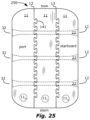
As illustrated in FIG. 25 , modular boat 250 comprises multiple sections 11 joined together by rod-connection(s) 32 and by interlock-connection(s) 141. Each section 12 can be physically separable from the other sections 11. Each section 12 can extend from bow to stern and can be joined to at least one other section 12 at a junction 13 extending from bow to stern. The rod-connection(s) and the interlock-connection(s) 141 can have a configuration as described above. Thus, the rod-connection(s) 32, the interlock-connection(s) 141, or both can be used with any example modular boat herein.
The multiple sections 11 in any of the modular boat embodiments described herein can be made of plastic with a hollow core or a foam-filled core. The holes 12 can be formed as a plastic cylinder. The holes 12 can be formed by drilling, or formed during molding.
Illustrated in FIG. 26 is a plate 261 for a removable roof rack. Illustrated in FIGS. 27-28 is a removable roof rack 270 including two separate plates 261. Each plate 261 can have two sides opposite of each other, including an inner-face 272 and an outer-face 273. The inner-faces 272 of the plates 261 can face each other.
Each plate 261 can have an edge-perimeter at an outer face and between the inner-face 272 and the outer-face 273. The edge-perimeter can include (a) a bottom-edge 266 facing down, (b) a top-edge 267 facing up, and (c) two end-edges 268 at opposite ends of the plate 261 between and linking the bottom-edge 266 and the top-edge 267.
A series of edge-holes 262, proximate the edge-perimeter, can provide locations for mounting the bars 271. For example, there can be a series of edge-holes 262 proximate to one or more of the following locations: (a) one or both of the two end-edges 268, (b) the bottom-edge 266, and (c) the top-edge 267. The edge-holes 262 can be sized and spaced for the multiple bars 271 to be removably-attached to each plate 261 and to connect the plates 261 to each other. Each series of edge-holes 262 can have equal spacing between adjacent edge-holes 262. Example spacing can be a number between 15 mm and 100 mm. There can be ≥2, ≥4, ≥8, or ≥20 edge-holes 262.
A width W of the sides 272 and 273 can be perpendicular to the ground. A length L of the sides 272 and 273 can be parallel to the ground. The width W and the length L can be perpendicular with respect to each other. A thickness Th of the sides 272 and 273, between the inner-face 272 and the outer-face 273, can be parallel to the ground. The thickness Th can be perpendicular to the width W and the length L.
The length L can be greater than the width W. The width w can be greater than the thickness Th. For example, 10≤W/Th, 15≤W/Th, 50≤W/Th, W/Th≤250, W/Th≤1000, 15≤L/Th, 25≤L/Th, 50≤L/Th, 200≤L/Th, L/Th≤300, L/Th≤1000, L/Th≤5000. Example sizes of the length L, width W, and thickness Th include: 1 mm≤Th≤25 mm, 20 cm≤W≤1 m, 1 m≤L≤4 m.
Each plate 261 can include one or more series S1, S2, S3 of rod-holes 26. Each series S1, S2, S3 can be parallel to the ground. The series S1, S2, S3 of rod-holes 26 of the separate plates 261 can be aligned with respect each other. The rod-holes 265 can be spaced and sized for holding equipment on the rack. For example, 15 mm≤D≤65 mm, where D265 is a diameter of the rod-holes 265. As illustrated in FIG. 27 , rods 22 can extend through the rod-holes 265 of the plates 261 and through the catamaran-holes 12 C in the sections 11 of the boat, to hold the boat on the rack. As illustrated in FIG. 28 , rods 22 can extend through the rod-holes 265 of the plates 261 and through the kayak-holes 12 K in the sections 11 of the boat, to hold the boat on the rack.
Each plate 261 can include a series of hand-holes 263 proximate to the top-edge 267, for carrying the plates 261. An example size of the hand-holes is ≥75 mm.
Each plate 261 can include a series of mounting-holes 264 proximate to the bottom-edge 266. The mounting-holes 264 can be used to mount the removable roof rack 270 to a permanent roof rack on the car, such as with a U-bolt or other roof rack bracket. An example size of the mounting-holes 264 is at least 25 mm across.
As illustrated in FIGS. 29-31 and 34-36 , a modular boat section 11 can include a bow, a stern, a port, and a starboard. The single section 11 can be used as a flotation device or a paddleboard.
The section 11 can include multiple holes 12 extending between port and starboard. For example, the section can include ≥1, ≥2, or ≥3 holes 12 and ≤3, ≤6, ≤10, or ≤25 holes 12.
Each hole 12 can have a protrusion 291 at one end. The protrusion 291 can surround this end of the hole 12. Each hole 12 can have a cavity 292 at an opposite end of the hole 12. The cavity 292 can surround the opposite end of the hole 12. The protrusion 291 can be sized to fit inside of the cavity 292 so that the protrusion 291 of the section 11 can mate with the cavity 292 of an identical section 11 (see FIGS. 33 and 37-39 ).
As illustrated in FIG. 32 , one section 11 can have protrusions 291 at both ends of its hole(s) 12. This section 11 can mate with another section 11 that has cavities 292 at both ends of its hole(s) 12.
As illustrated in FIGS. 29-33 and 40 , the bow of the section 11 can have a convex shape and the stern can have a concave shape. The convex shape can match the concave shape so that (a) the bow of the section 11 can mate with the stern of another section, which can be an identical section 11, and (b) the stern of the section 11 can mate with the bow of another section, which can be an identical section 11.
As illustrated in FIGS. 34-37 , the bow can slope from top 12 T to bottom 12 B, lengthening the section 11 at the top 12 T and shortening the section 11 at the bottom 12 B. The stern can slope from a bottom 12 B to a top 12 T, lengthening the section 11 at the bottom 12 B and shortening the section 11 at the top 12 T. The top 12 T of the section 11 can be identical in shape to the bottom of the section 11. The top 12 T of the section 11 and the bottom of the section can have a rectangular shape, offset longitudinally with respect to each other.
As illustrated in FIGS. 38-39 , the slope at the bow can match the slope at the stern so that (a) the bow of the section 11 can mate with the stern of another section, which can be an identical section 11, and (b) the stern of the section 11 can mate with the bow of another section, which can be an identical section 11.
As illustrated in FIGS. 32-33 and 37-40 , a modular boat can include two sections 11. The sections 11 can be identical. Each section 11 can include a bow, a stern, a port, and a starboard. A port of one of the sections 11 can be adjacent to or can adjoin the starboard of the other section 11.
The two sections 11 can include multiple pairs of holes 12. Each pair can include a hole 12 from each of the two sections 11 aligned with each other. Each hole 12 can extend between port and starboard of the section 11 it is in.
The pair of holes 12 can join together at a junction 321. Each junction 321 can include the protrusion 291 inserted into and mating with a cavity 292 of the other hole 12.
A rod 22 can extend through each of the pairs of holes 12. Each rod 22 can be removable to allow separation of the sections 11. The rod 22 and the holes 12 can have characteristics as described above.
Each rod 22 can have a locking-rod-end 22 L including ≥three sides, ≥four sides, ≥five sides, or ≥six sides. The rod 22 can shorten its length, as described above, pulling the locking-rod-end 22 L and an opposite end towards each other, and pressing the two sections 11 of the modular boat together. The rod 22 can shorten its length by rotating the opposite end. The opposite end of each rod 22 can be a round-rod-end 22 R.
Each hole 12 can have a locking-hole-end 12 L including ≥three sides, ≥four sides, ≥five sides, or ≥six sides, which can match or mate with the sides of the locking-rod-end 22 L and hold the locking-rod-end 22 L of the rod 22 in place while the opposite end rotates. Both ends of each hole 12 can be locking-hole-ends 12 L.
As illustrated in FIG. 33 , modular boat 330 can include a front section 11 F, a back section 11 B, and a side section 11 S. The bow of the back section 11 B can have a convex shape. The stern of the front section 11 F can have a concave shape. The convex shape can match the concave shape. As illustrated in FIG. 38 , modular boat 380 can include a front section 11 F, a back section 11 B, and a side section 11 S. A sloping bow of the back section 11 B can match and mate with a sloping stern of the front section 11 F.
Thus, in modular boats 330 and 380, the bow of the back section 11 B can adjoin and mate with the stern of the front section 11 F, the back section 11 B and the front section 11 F forming a longitudinal pair. The side section 11 S can adjoin both sections 11 F and 11 B of the longitudinal pair. The back section 11 B, the front section 11 F, and the side section 11 can be identical.
One of the rods 22 can extend through a pair of holes 12 of the front section 11 F and the side section 11 S. Another of the rods 22 can extend through holes 12 of the back section 11 B and the side section 11 S.
As illustrated in FIG. 40 , a flotation device 400 can include many sections 11, some joined side by side, and some joined bow to stern. A rod 22 (not shown) can extend through each group of holes 12, through all sections aligned with each hole. In FIG. 40 , most holes 12 extend through eight sections. The flotation device 340 can be a modular boat, a dock, a raft, or a bridge. Sections 11 like the section 11 in FIGS. 29-33 are illustrated in FIG. 40 . Each of these sections 11 could be replaced by the section 11 of FIGS. 34-39 .
Example materials for the sections 11 in all the embodiments herein include a plastic shell with a hollow core, Styrofoam, or a Styrofoam core with a plastic exterior. The plastic exterior can be formed by rotomold. Alternatively, a plastic sheet can be heated and vacuum fit to a mold. Styrofoam can be formed in a mold on top. The plastic can coat a bottom of each section, a surface of the core facing the holes 12, or both. Hollow plastic tubes can be inserted into each hole 12 for protection of the hole 12.
Example materials for the rods 22 include aluminum, stainless steel, or plastic. Example materials for the plates 261 include aluminum, stainless steel, or plastic.
Claims (20)
1. A modular boat comprising:
two sections, each including a bow, a stern, a port, and a starboard;
a port of one of the sections adjacent to the starboard of the other section;
multiple pairs of holes, each pair including a hole from each of the two sections aligned with each other, each hole extending between port and starboard of the section it is in;
the pair of holes joining together at a junction, each junction including a protrusion surrounding an end of one of the holes inserted into and mating with a cavity surrounding an end of the other hole; and
multiple rods, each extending through one of the pairs of holes, the rods being removable to allow separation of the sections.
2. The modular boat of claim 1 , further comprising:
a back section having the same characteristics as the two sections;
the two sections include a front section and a side section;
the bow of all of the sections slope from a top to a bottom of the section, lengthening the section at the top and shortening the section at the bottom;
the stern of all of the sections slope from a bottom to a top of the section, lengthening the section at the bottom and shortening the section at the top;
the slope at the bow matches the slope at the stern;
the bow of the back section adjoins and mates with the stern of the front section, the back section and the front section forming a longitudinal pair;
the side section adjoins a side of both sections of the longitudinal pair; and
one of the rods extends through holes of the front section and the side section and one of the rods extends through holes of the front section and the back section.
3. The modular boat of claim 2 , wherein the top of each section is identical in shape with the bottom of each section.
4. The modular boat of claim 2 , wherein the top of each section and the bottom of each section have a rectangular shape, offset longitudinally with respect to each other.
5. The modular boat of claim 1 , further comprising:
a back section having the same characteristics as the two sections;
the two sections include a front section and a side section;
the bow of the front section, the side section, and the back section each has a convex shape;
the stern of the front section, the side section, and the back section each has a concave shape;
the convex shape matches the concave shape;
the bow of the back section adjoins and mates with the stern of the front section, the back section and the front section forming a longitudinal pair, and the side section adjoins a side of both sections of the longitudinal pair; and
one of the rods extends through holes of the front section and the side section and one of the rods extends through holes of the front section and the back section.
6. The modular boat of claim 1 , further comprising:
each rod has a locking-rod-end including three sides, the rod is capable of shortening its length, pulling the locking-rod-end and an opposite end towards each other, and pressing the two sections of the modular boat together, by rotating the opposite end;
each hole has a locking-hole-end including three sides; and
the three sides of the locking-hole-end is capable of mating with the three sides of the locking-rod-end and holding the locking-rod-end of the rod in place while the opposite end rotates.
7. A modular boat comprising:
two sections, each including a bow, a stern, a port, and a starboard;
a port of one of the sections adjacent to the starboard of the other section;
multiple pairs of holes, each pair including a hole from each of the two sections aligned with each other, each hole extending between port and starboard of the section it is in;
multiple rods, each rod extending through one of the pairs of holes, the rods being removable to allow separation of the sections;
each rod has a locking-rod-end including three sides, the rod is capable of shortening its length, pulling the locking-rod-end and an opposite end towards each other, and pressing the two sections of the modular boat together;
each hole has a locking-hole-end including three sides; and
the three sides of the locking-hole-end is capable of mating with the three sides of the locking-rod-end and holding the locking-rod-end of the rod in place while the opposite end rotates.
8. The modular boat of claim 7 , wherein the rod is capable of shortening its length by rotating the opposite end.
9. The modular boat of claim 7 , wherein the opposite end of each rod is a round-rod-end.
10. The modular boat of claim 9 , wherein both ends of each hole is a locking-hole-end with three sides.
11. The modular boat of claim 7 , wherein the locking-rod-end and the locking-hole-end each include six sides.
12. The modular boat of claim 7 , wherein the sections are identical.
13. The modular boat of claim 7 , further comprising:
a back section having the same characteristics as the two sections in claim 3 ;
the bow of the two sections and of the back section has a convex shape;
the stern of the two sections and of the back section has a concave shape;
the convex shape matches the concave shape;
the bow of the back section adjoins and mates with the stern of one of the two sections, defining a front section, the back section and the front section forming a longitudinal pair, and the other of the two sections, defining a side section, adjoins both sections of longitudinal pair; and
one of the rods extends through holes of the front section and the side section and one of the rods extends through holes of the front section and the back section.
14. A removable roof rack for a modular boat with multiple sections capable of being joined between at the port and starboard sides by a rod extending through both sections, the removable roof rack comprising:
two separate plates, each plate comprising two sides opposite of each other, including an inner-face and an outer-face, the inner-faces of the plates facing each other;
a width of the sides is perpendicular to the ground;
a length of the sides is parallel to the ground;
10≤W/Th and 25≤L/Th, where Th is a thickness of each plate between the inner-face and the outer-face, W is the width of the sides, and L is the length of the sides;
multiple bars extending between the plates and attaching the plates to each other.
15. The rack of claim 14 , further comprising the multiple sections of the modular boat between the plates of the roof rack and multiple rods holding the modular boat on the roof rack, each rod extending through a hole of each of sections.
16. The rack of claim 14 , further comprising:
a series of rod-holes through each of the plates, the series being parallel to the ground;
the series of the separate plates are aligned with respect each other;
the rod-holes spaced and sized for holding equipment on the rack; and
15 mm≤D265≤65 mm, where D265 is a diameter of the rod-holes.
17. The rack of claim 14 , further comprising:
three series of rod-holes through each of the plates, each series being parallel to the ground;
each of the series of the separate plates are aligned with respect each other;
the rod-holes spaced and sized for holding equipment on the rack; and
15 mm≤D265≤65 mm, where D265 is a diameter of the rod-holes.
18. The rack of claim 14 , further comprising:
a series of rod-holes through each of the plates, the series being parallel to the ground; and
15 mm≤D265≤65 mm, where D265 is a diameter of the rod-holes.
19. The rack of claim 14 , further comprising:
an edge-perimeter of each plate between the inner-face and the outer-face;
the edge-perimeter including (a) a bottom-edge facing down, (b) a top-edge facing up, and (c) two end-edges at opposite ends of the plate between and linking the bottom-edge and the top-edge;
a series of edge-holes, proximate the bottom-edge, proximate the top-edge, or both, the edge-holes sized and spaced for the multiple bars to be removably-attached to each plate and to connect the plates to each other.
20. The rack of claim 19 , wherein the series of edge-holes have equal spacing between adjacent edge-holes, the spacing being a number between 15 mm and 100 mm.
Priority Applications (1)
| Application Number | Priority Date | Filing Date | Title |
|---|---|---|---|
| US17/535,755 US12024268B2 (en) | 2020-12-08 | 2021-11-26 | Modular boat |
Applications Claiming Priority (3)
| Application Number | Priority Date | Filing Date | Title |
|---|---|---|---|
| US202063122516P | 2020-12-08 | 2020-12-08 | |
| US202163225479P | 2021-07-24 | 2021-07-24 | |
| US17/535,755 US12024268B2 (en) | 2020-12-08 | 2021-11-26 | Modular boat |
Publications (2)
| Publication Number | Publication Date |
|---|---|
| US20220177078A1 US20220177078A1 (en) | 2022-06-09 |
| US12024268B2 true US12024268B2 (en) | 2024-07-02 |
Family
ID=81849950
Family Applications (1)
| Application Number | Title | Priority Date | Filing Date |
|---|---|---|---|
| US17/535,755 Active 2043-03-09 US12024268B2 (en) | 2020-12-08 | 2021-11-26 | Modular boat |
Country Status (1)
| Country | Link |
|---|---|
| US (1) | US12024268B2 (en) |
Citations (11)
| Publication number | Priority date | Publication date | Assignee | Title |
|---|---|---|---|---|
| US157546A (en) * | 1874-12-08 | Improvement in ice-breaking boats | ||
| US1920036A (en) * | 1932-07-29 | 1933-07-25 | Elmer E Stoner | Swimming machine |
| US2432857A (en) * | 1943-08-16 | 1947-12-16 | Henry C Briggs | Ship propulsion system |
| US2589087A (en) * | 1950-04-22 | 1952-03-11 | Jarvi Reino | Collapsible boat |
| US3426716A (en) * | 1967-07-28 | 1969-02-11 | Andrew T Hackworth | Pontoon boat construction |
| US3593684A (en) * | 1969-09-05 | 1971-07-20 | Joseph A Cogliano | Collapsible catamaran |
| US5692450A (en) * | 1995-09-12 | 1997-12-02 | Alter; Hobart L. | One man fishing vessel |
| US7587986B2 (en) * | 2006-03-24 | 2009-09-15 | Tillicum International, Inc. | Modular personal pontoon boat |
| US8074593B2 (en) * | 2008-05-02 | 2011-12-13 | Jeffrey Hansen | Watercraft attachment device |
| CN102781769A (en) * | 2009-12-30 | 2012-11-14 | 亚历克斯·R·凯和弗朗西斯·凯信托 | Collapsible boat with inflatable parts |
| US11952086B2 (en) * | 2019-07-25 | 2024-04-09 | Aqua-Spider, LLC | Human powered catamaran-styled watercraft and methods |
-
2021
- 2021-11-26 US US17/535,755 patent/US12024268B2/en active Active
Patent Citations (11)
| Publication number | Priority date | Publication date | Assignee | Title |
|---|---|---|---|---|
| US157546A (en) * | 1874-12-08 | Improvement in ice-breaking boats | ||
| US1920036A (en) * | 1932-07-29 | 1933-07-25 | Elmer E Stoner | Swimming machine |
| US2432857A (en) * | 1943-08-16 | 1947-12-16 | Henry C Briggs | Ship propulsion system |
| US2589087A (en) * | 1950-04-22 | 1952-03-11 | Jarvi Reino | Collapsible boat |
| US3426716A (en) * | 1967-07-28 | 1969-02-11 | Andrew T Hackworth | Pontoon boat construction |
| US3593684A (en) * | 1969-09-05 | 1971-07-20 | Joseph A Cogliano | Collapsible catamaran |
| US5692450A (en) * | 1995-09-12 | 1997-12-02 | Alter; Hobart L. | One man fishing vessel |
| US7587986B2 (en) * | 2006-03-24 | 2009-09-15 | Tillicum International, Inc. | Modular personal pontoon boat |
| US8074593B2 (en) * | 2008-05-02 | 2011-12-13 | Jeffrey Hansen | Watercraft attachment device |
| CN102781769A (en) * | 2009-12-30 | 2012-11-14 | 亚历克斯·R·凯和弗朗西斯·凯信托 | Collapsible boat with inflatable parts |
| US11952086B2 (en) * | 2019-07-25 | 2024-04-09 | Aqua-Spider, LLC | Human powered catamaran-styled watercraft and methods |
Also Published As
| Publication number | Publication date |
|---|---|
| US20220177078A1 (en) | 2022-06-09 |
Similar Documents
| Publication | Publication Date | Title |
|---|---|---|
| US4478167A (en) | Coupling system for a multiple sectioned boat | |
| US2666933A (en) | Sectional boat | |
| ES2895766T3 (en) | Multi-Grip Allen Bit | |
| US8327792B2 (en) | Canoe with multiple hull sections | |
| US9150288B2 (en) | Surfboard having interchangeable tail extensions | |
| US12024268B2 (en) | Modular boat | |
| US20110207376A1 (en) | Sectionalized sports board | |
| US7343837B1 (en) | Multi-plane flexible handle for ratchets and wrenches | |
| US20160194061A1 (en) | Canoe having two disconnectable hull sections | |
| US20060252317A1 (en) | Paddle shaft coupler | |
| US7281456B2 (en) | Tool set | |
| WO2015190777A1 (en) | Detachable fin box | |
| US4856150A (en) | Container coupler | |
| US11406093B2 (en) | Extensible pole coupling assembly | |
| US7322265B2 (en) | Compound screwdriver head | |
| US7395773B1 (en) | Multi-part boat | |
| KR101721809B1 (en) | Assembling Surfing board | |
| USH2277H1 (en) | Modular towable platform | |
| US11738831B2 (en) | Reconfigurable watercraft | |
| US4319853A (en) | Geodesic dome structure tie-beam connector | |
| WO2023037132A1 (en) | Structure for connecting device, particularly for connecting sport cameras to base bodies | |
| CN210420182U (en) | Single-plate type marine sacrificial anode mounting accessory | |
| GB2432814A (en) | A sectional water craft incorporating tongue and groove joints | |
| US20070277722A1 (en) | Multi-person racing canoe | |
| CN218271347U (en) | A propeller detection device |
Legal Events
| Date | Code | Title | Description |
|---|---|---|---|
| STPP | Information on status: patent application and granting procedure in general |
Free format text: DOCKETED NEW CASE - READY FOR EXAMINATION |
|
| STPP | Information on status: patent application and granting procedure in general |
Free format text: NOTICE OF ALLOWANCE MAILED -- APPLICATION RECEIVED IN OFFICE OF PUBLICATIONS |
|
| STPP | Information on status: patent application and granting procedure in general |
Free format text: PUBLICATIONS -- ISSUE FEE PAYMENT VERIFIED |
|
| STCF | Information on status: patent grant |
Free format text: PATENTED CASE |