US12021546B2 - Method and apparatus for improved belief propagation based decoding - Google Patents
Method and apparatus for improved belief propagation based decoding Download PDFInfo
- Publication number
- US12021546B2 US12021546B2 US18/022,215 US202018022215A US12021546B2 US 12021546 B2 US12021546 B2 US 12021546B2 US 202018022215 A US202018022215 A US 202018022215A US 12021546 B2 US12021546 B2 US 12021546B2
- Authority
- US
- United States
- Prior art keywords
- message associated
- conflict
- sign
- vpe
- potential
- Prior art date
- Legal status (The legal status is an assumption and is not a legal conclusion. Google has not performed a legal analysis and makes no representation as to the accuracy of the status listed.)
- Active
Links
- 238000000034 method Methods 0.000 title claims abstract description 66
- 238000012545 processing Methods 0.000 claims abstract description 24
- 238000012795 verification Methods 0.000 claims abstract description 8
- 230000004044 response Effects 0.000 claims description 20
- 230000006870 function Effects 0.000 claims description 18
- 230000015654 memory Effects 0.000 claims description 11
- 238000004590 computer program Methods 0.000 claims description 10
- 230000000717 retained effect Effects 0.000 claims description 4
- 238000004891 communication Methods 0.000 description 47
- 238000010586 diagram Methods 0.000 description 24
- 230000005540 biological transmission Effects 0.000 description 12
- 238000005259 measurement Methods 0.000 description 9
- 230000008901 benefit Effects 0.000 description 8
- 238000012546 transfer Methods 0.000 description 7
- 238000003491 array Methods 0.000 description 4
- 238000010276 construction Methods 0.000 description 4
- 238000012544 monitoring process Methods 0.000 description 4
- 230000008569 process Effects 0.000 description 3
- 238000004088 simulation Methods 0.000 description 3
- 238000007476 Maximum Likelihood Methods 0.000 description 2
- 238000004364 calculation method Methods 0.000 description 2
- 230000001413 cellular effect Effects 0.000 description 2
- 125000004122 cyclic group Chemical group 0.000 description 2
- 238000012986 modification Methods 0.000 description 2
- 230000004048 modification Effects 0.000 description 2
- 230000011664 signaling Effects 0.000 description 2
- 230000006978 adaptation Effects 0.000 description 1
- 239000000654 additive Substances 0.000 description 1
- 230000000996 additive effect Effects 0.000 description 1
- 238000001514 detection method Methods 0.000 description 1
- 230000000694 effects Effects 0.000 description 1
- 238000005516 engineering process Methods 0.000 description 1
- 230000007774 longterm Effects 0.000 description 1
- 238000013507 mapping Methods 0.000 description 1
- 230000003287 optical effect Effects 0.000 description 1
- 230000004043 responsiveness Effects 0.000 description 1
- 230000002441 reversible effect Effects 0.000 description 1
- 239000007787 solid Substances 0.000 description 1
- 230000009466 transformation Effects 0.000 description 1
- 230000003245 working effect Effects 0.000 description 1
Images


Classifications
-
- H—ELECTRICITY
- H03—ELECTRONIC CIRCUITRY
- H03M—CODING; DECODING; CODE CONVERSION IN GENERAL
- H03M13/00—Coding, decoding or code conversion, for error detection or error correction; Coding theory basic assumptions; Coding bounds; Error probability evaluation methods; Channel models; Simulation or testing of codes
- H03M13/03—Error detection or forward error correction by redundancy in data representation, i.e. code words containing more digits than the source words
- H03M13/05—Error detection or forward error correction by redundancy in data representation, i.e. code words containing more digits than the source words using block codes, i.e. a predetermined number of check bits joined to a predetermined number of information bits
- H03M13/13—Linear codes
-
- H—ELECTRICITY
- H03—ELECTRONIC CIRCUITRY
- H03M—CODING; DECODING; CODE CONVERSION IN GENERAL
- H03M13/00—Coding, decoding or code conversion, for error detection or error correction; Coding theory basic assumptions; Coding bounds; Error probability evaluation methods; Channel models; Simulation or testing of codes
- H03M13/03—Error detection or forward error correction by redundancy in data representation, i.e. code words containing more digits than the source words
- H03M13/05—Error detection or forward error correction by redundancy in data representation, i.e. code words containing more digits than the source words using block codes, i.e. a predetermined number of check bits joined to a predetermined number of information bits
- H03M13/11—Error detection or forward error correction by redundancy in data representation, i.e. code words containing more digits than the source words using block codes, i.e. a predetermined number of check bits joined to a predetermined number of information bits using multiple parity bits
- H03M13/1102—Codes on graphs and decoding on graphs, e.g. low-density parity check [LDPC] codes
- H03M13/1105—Decoding
- H03M13/1128—Judging correct decoding and iterative stopping criteria other than syndrome check and upper limit for decoding iterations
-
- H—ELECTRICITY
- H03—ELECTRONIC CIRCUITRY
- H03M—CODING; DECODING; CODE CONVERSION IN GENERAL
- H03M13/00—Coding, decoding or code conversion, for error detection or error correction; Coding theory basic assumptions; Coding bounds; Error probability evaluation methods; Channel models; Simulation or testing of codes
- H03M13/03—Error detection or forward error correction by redundancy in data representation, i.e. code words containing more digits than the source words
- H03M13/05—Error detection or forward error correction by redundancy in data representation, i.e. code words containing more digits than the source words using block codes, i.e. a predetermined number of check bits joined to a predetermined number of information bits
- H03M13/11—Error detection or forward error correction by redundancy in data representation, i.e. code words containing more digits than the source words using block codes, i.e. a predetermined number of check bits joined to a predetermined number of information bits using multiple parity bits
- H03M13/1102—Codes on graphs and decoding on graphs, e.g. low-density parity check [LDPC] codes
- H03M13/1191—Codes on graphs other than LDPC codes
-
- H—ELECTRICITY
- H03—ELECTRONIC CIRCUITRY
- H03M—CODING; DECODING; CODE CONVERSION IN GENERAL
- H03M13/00—Coding, decoding or code conversion, for error detection or error correction; Coding theory basic assumptions; Coding bounds; Error probability evaluation methods; Channel models; Simulation or testing of codes
- H03M13/03—Error detection or forward error correction by redundancy in data representation, i.e. code words containing more digits than the source words
- H03M13/05—Error detection or forward error correction by redundancy in data representation, i.e. code words containing more digits than the source words using block codes, i.e. a predetermined number of check bits joined to a predetermined number of information bits
- H03M13/11—Error detection or forward error correction by redundancy in data representation, i.e. code words containing more digits than the source words using block codes, i.e. a predetermined number of check bits joined to a predetermined number of information bits using multiple parity bits
- H03M13/1102—Codes on graphs and decoding on graphs, e.g. low-density parity check [LDPC] codes
- H03M13/1105—Decoding
- H03M13/1111—Soft-decision decoding, e.g. by means of message passing or belief propagation algorithms
Definitions
- the present disclosure generally relates to wireless communications, and more specifically, to a method and apparatus for improved belief propagation (BP) based decoding.
- BP belief propagation
- Polar code has attracted much attention since its birth in 2008. It can achieve Shannon capacity with very simple encoding and decoding.
- polar coding has been adopted as channel coding for a control channel in case of enhanced mobile broadband (eMBB) service.
- eMBB enhanced mobile broadband
- SC Successive Cancellation
- BP Belief Propagation
- Successive Cancellation List (SCL) decoding was introduced which can achieve maximum likelihood (ML) bound with sufficiently large list size.
- SCL Successive Cancellation List
- BPL Belief Propagation List
- the present disclosure proposes an improved BP based decoding solution, which may be referred to as Belief Propagation Conflict Search List (BPCSL) decoding.
- BPCSL Belief Propagation Conflict Search List
- a method performed by a receiver comprises obtaining based on received information and an original left-to-right table comprising left-to-right messages associated with nodes of a plurality of processing elements (PEs) for BP decoding, an original right-to-left table comprising right-to-left messages associated with the nodes, and searching for, based on the original left-to-right table and the original right-to-left table, a conflict verification processing element (VPE) in the plurality of PE.
- PEs processing elements
- VPE conflict verification processing element
- the conflict VPE is a VPE for which the left-to-right messages associated with the most-left nodes affecting the left-to-right message associated with its left-upper node indicate frozen bits and the left-to-right messages associated with the most-left nodes affecting the left-to-right message associated with its left-lower node indicate frozen bits and information bits, and has a negative sign for the right-to-left message associated with its left-upper node.
- the method also comprises updating the original right-to-left table based on the conflict VPE to obtain a plurality of potential right-to-left tables, and performing the BP decoding based on the respective one of the plurality of potential right-to-left tables.
- updating the original right-to-left table based on the conflict VPE to obtain a plurality of potential right-to-left tables may comprise modifying, for the conflict VPE and in the original right-to-left table, the sign of the right-to-left message associated with its left-upper node to be positive and the sign of the right-to-left message associated with its right-upper node to be the same as the sign of the right-to-left message associated with its right-lower node, to obtain a first potential right-to-left table, and modifying, for the conflict VPE and in the original right-to-left table, the sign of the right-to-left message associated with its left-upper node to be positive and the sign of the right-to-left message associated with its right-lower node to be the same as the sign of the right-to-left message associated with its right-upper node, to obtain a second potential right-to-left table.
- the method may further comprise searching for, in response to no BP decoding based on the respective one of the plurality of potential right-to-left tables being successful, a conflict PE which is connected leftwards to the found conflict VPE and has the right-to-left message associated with the left-upper node or the left-lower node changed or a new conflict VPE based on the respective potential right-to-left tables, and updating each of the potential right-to-left tables based on the respective conflict PE or the respective new conflict VPE.
- the BP decoding may be performed based on the respective one of the updated potential right-to-left tables.
- updating each of the potential right-to-left tables based on the respective conflict PE may comprise, in response to the right-to-left message associated with the conflict PE's left-upper node being changed, modifying, for the conflict PE and in the potential right-to-left table, the sign of the right-to-left message associated with its right-upper node based on the sign of the right-to-left message associated with its left-upper node and the sign of the right-to-left message associated with its right-lower node, to obtain a third potential right-to-left table, and modifying, for the conflict PE and in the potential right-to-left table, the sign of the right-to-left message associated with its right-lower node based on the sign of the right-to-left message associated with its left-upper node and the sign of the right-to-left message associated with its right-upper node, to obtain a fourth potential right-to-left table; in response to the right-to-left message associated with the conflict PE's
- updating the original right-to-left table based on the conflict VPE to obtain a plurality of potential right-to-left tables may comprise modifying, for the conflict VPE and in the original right-to-left table, the sign of the right-to-left message associated with its left-upper node to be positive and the sign of the right-to-left message associated with its right-upper node to be the same as the sign of the right-to-left message associated with its right-lower node, to obtain a first intermediate right-to-left table; modifying, for the conflict VPE and in the original right-to-left table, the sign of the right-to-left message associated with its left-upper node to be positive and the sign of the right-to-left message associated with its right-lower node to be the same as the sign of the right-to-left message associated with its right-upper node, to obtain a second intermediate right-to-left table; searching each of the first intermediate right-to-left table and the second intermediate right-to-to-
- the method may further comprise searching for, in response to no BP decoding based on the respective one of the potential right-to-left tables or the updated potential right-to-left tables being successful, a further conflict PE which is connected leftwards to the previously found conflict PE and has the right-to-left message associated with the left-upper node or the left-lower node changed or a new conflict VPE based on the respective one of the potential right-to-left tables or the updated potential right-to-left tables, and updating each of the potential right-to-left tables or the updated potential right-to-left tables based on the respective further conflict PE or the new conflict VPE.
- the BP decoding may be performed based on the respective one of the newly updated potential right-to-left tables.
- the method may further comprise prior to searching the conflict PE or the new conflict VPE: determining whether an amount N of the potential right-to-left tables is greater than a predetermined number, calculating, in response to the amount of the potential right-to-left tables being greater than the predetermined number, a power metric for each BP decoding based on the respective potential right-to-left table, and retaining the predetermined number of potential right-to-left tables with the smaller power metric. Further, the searching of the conflict PE or the new conflict VPE may be performed on the retained potential right-to-left tables.
- the power metric for the BP decoding is calculated as follows:
- PM(l) represents the power metric for the l th BP decoding
- l is in a range from 1 to 2*N and comprising 1 and 2*N
- N_frozen represents a total number of the most-left nodes indicating the frozen bit
- llr k_frozen (l) represents the right-to-left message associated with the k_frozen th most-left node which indicates the frozen bit in the form of logarithmic likelihood ratio
- LLR in the last right-to-left table during the BP decoding
- ln( ⁇ ) represents a logarithmic function with base e.
- the method may further comprise prior to obtaining the original right-to-left table, performing the BP decoding on the received information. Further, the obtaining of the original right-to-left table may be performed in response to the BP decoding being unsuccessful.
- the BP decoding may be determined as being unsuccessful if one of the followings is satisfied: a) iteration times of the BP decoding exceed maximum iteration times, and b) the current left-to-right table and the current right-to-left table are identical to the previous left-to-right table and the previous right-to-left table respectively.
- the left-to-right message and the right-to-left message may be in the form of logarithmic likelihood ratio, LLR.
- the left-to-right messages associated with the most-left nodes may be set based on bit positions of information bits and frozen bits in a source bit sequence from which the received information is originated.
- the left-to-right message associated with the most-left node indicating the information bit may be set to a first value and the left-to-right message associated with the most-left node indicating the frozen bit may be set to a second value.
- searching for the conflict VPE may comprise checking, for each of the plurality PEs and based on the left-to-right table, the left-to-right messages associated with the left-upper node and the left-lower node, determining the PE of which the left-to-right message associated with its left-upper node has a larger value than the left-to-right message associated with its left-lower node as a verification processing element, checking, for the VPE and based on the right-ot-left table, whether the right-to-left message associated with the left-upper node has a negative sign, and determining, in response to the right-to-left message associated with the left-upper node having the negative sign, the VPE as the conflict VPE.
- the searching of the conflict VPE may be performed starting from the most-right PEs.
- a receiver may comprise one or more processors and one or more memories comprising computer program codes.
- the one or more memories and the computer program codes may be configured to, with the one or more processors, cause the receiver at least to perform any step of the method according to the first aspect of the present disclosure.
- a receiver may comprise a BP decoder configured to perform BP decoding, and a BP conflict search list circuitry configured to obtain, based on the received information and an original left-to-right table comprising left-to-right messages associated with nodes of a plurality of processing elements, PEs, for the BP decoding, an original right-to-left table comprising right-to-left messages associated with the nodes; search for, based on the original left-to-right table and the original right-to-left table, a conflict verification processing element, VPE, in the plurality of PEs, the conflict VPE being a VPE for which the left-to-right messages associated with the most-left nodes affecting the left-to-right message associated with its left-upper node indicate frozen bits and the left-to-right messages associated with the most-left nodes affecting the left-to-right message associated with its left-lower node indicate frozen bits and information bits, and having a negative sign for
- a computer-readable medium having computer program codes embodied thereon which, when executed on a computer, cause the computer to perform any step of the method according to the first aspect of the present disclosure.
- FIG. 1 is a simplified diagram of a communication system in which polar code is utilized
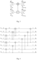
- FIG. 2 is a diagram illustrating 8-bit polar code construction
- FIG. 3 is a diagram illustrating a processing element (PE) for the BP decoding
- FIG. 4 is a diagram illustrating an example left-to-right table of the 8-bit polar code shown in FIG. 2 ;
- FIG. 5 is a flowchart illustrating a method for BPCSL decoding performed by a receiver according to some embodiments of the present disclosure
- FIGS. 6 A and 6 B are diagrams illustrating an example of the original left-to-right table and the original right-to-left table of a (16, 8) polar code according to some embodiments of the present disclosure
- FIGS. 7 A and 7 B are diagrams illustrating an example of the potential right-to-left table based on the original right-to-left table in FIG. 6 B ;
- FIG. 8 is a flowchart illustrating the method for BPCSL decoding according to some embodiments of the present disclosure
- FIGS. 9 A and 9 B are diagrams illustrating an example of the potential right-to-left table obtained by updating the potential right-to-left table in FIG. 7 A ;
- FIGS. 10 A and 10 B are diagrams illustrating an example of the potential right-to-left table obtained by updating the potential right-to-left table in FIG. 7 B ;
- FIGS. 11 A and 11 B are diagrams illustrating an example of the potential right-to-left table obtained by updating the potential right-to-left table in FIG. 9 A ;
- FIG. 12 is a diagram illustrating an example searching tree which reflects the updating of the potential right-to-left table from FIG. 6 B to FIGS. 7 A and 7 B , and from FIGS. 7 A and 7 B to FIGS. 9 A, 9 B, 10 A and 10 B respectively;
- FIG. 13 is a diagram illustrating simulation results of block error rate (BLER) for decoding 64-bit sequence
- FIG. 14 is a diagram illustrating simulation results of BLER for decoding 128-bit sequence
- FIG. 15 is a block diagram illustrating an apparatus according to some embodiments of the present disclosure.
- FIG. 16 is a block diagram illustrating an apparatus according to some embodiments of the present disclosure.
- FIG. 17 is a block diagram illustrating a telecommunication network connected via an intermediate network to a host computer in accordance with some embodiments of the present disclosure
- FIG. 18 is a block diagram illustrating a host computer communicating via a base station with a UE over a partially wireless connection in accordance with some embodiments of the present disclosure
- FIG. 19 is a flowchart illustrating a method implemented in a communication system, in accordance with an embodiment of the present disclosure.
- FIG. 20 is a flowchart illustrating a method implemented in a communication system, in accordance with an embodiment of the present disclosure
- FIG. 21 is a flowchart illustrating a method implemented in a communication system, in accordance with an embodiment of the present disclosure.
- FIG. 22 is a flowchart illustrating a method implemented in a communication system, in accordance with an embodiment of the present disclosure.
- the term “communication network” refers to a network following any suitable communication standards, such as new radio (NR), long term evolution (LTE), LTE-Advanced, wideband code division multiple access (WCDMA), high-speed packet access (HSPA), and so on.
- NR new radio
- LTE long term evolution
- WCDMA wideband code division multiple access
- HSPA high-speed packet access
- the communications between a terminal device and a network node in the communication network may be performed according to any suitable generation communication protocols, including, but not limited to, the first generation (1G), the second generation (2G), 2.5G, 2.75G, the third generation (3G), 4G, 4.5G, 5G communication protocols, and/or any other protocols either currently known or to be developed in the future.
- network node refers to a network device in a communication network via which a terminal device accesses to the network and receives services therefrom.
- the network node or network device may refer to a base station (BS), an access point (AP), a multi-cell/multicast coordination entity (MCE), a controller or any other suitable device in a wireless communication network.
- BS base station
- AP access point
- MCE multi-cell/multicast coordination entity
- the BS may be, for example, a node B (NodeB or NB), an evolved NodeB (eNodeB or eNB), a next generation NodeB (gNodeB or gNB), an IAB node, a remote radio unit (RRU), a radio header (RH), a remote radio head (RRH), a relay, a low power node such as a femto, a pico, and so forth.
- NodeB or NB node B
- eNodeB or eNB evolved NodeB
- gNodeB or gNB next generation NodeB
- IAB node IAB node
- RRU remote radio unit
- RH radio header
- RRH remote radio head
- relay a low power node such as a femto, a pico, and so forth.
- the network node comprise multi-standard radio (MSR) radio equipment such as MSR BS s, network controllers such as radio network controllers (RNCs) or base station controllers (BSCs), base transceiver stations (BTSs), transmission points, transmission nodes, positioning nodes and/or the like. More generally, however, the network node may represent any suitable device (or group of devices) capable, configured, arranged, and/or operable to enable and/or provide a terminal device access to a wireless communication network or to provide some service to a terminal device that has accessed to the wireless communication network.
- MSR multi-standard radio
- RNCs radio network controllers
- BSCs base station controllers
- BTSs base transceiver stations
- transmission points transmission nodes
- positioning nodes positioning nodes and/or the like.
- the network node may represent any suitable device (or group of devices) capable, configured, arranged, and/or operable to enable and/or provide a terminal device access to a wireless communication network or to provide some service to
- terminal device refers to any end device that can access a communication network and receive services therefrom.
- the terminal device may refer to a user equipment (UE), or other suitable devices.
- the UE may be, for example, a subscriber station, a portable subscriber station, a mobile station (MS) or an access terminal (AT).
- the terminal device may include, but not limited to, portable computers, image capture terminal devices such as digital cameras, gaming terminal devices, music storage and playback appliances, a mobile phone, a cellular phone, a smart phone, a tablet, a wearable device, a personal digital assistant (PDA), a vehicle, and the like.
- PDA personal digital assistant
- a terminal device may also be called an IoT device and represent a machine or other device that performs monitoring, sensing and/or measurements etc., and transmits the results of such monitoring, sensing and/or measurements etc. to another terminal device and/or a network equipment.
- the terminal device may in this case be a machine-to-machine (M2M) device, which may in a 3rd generation partnership project (3GPP) context be referred to as a machine-type communication (MTC) device.
- M2M machine-to-machine
- 3GPP 3rd generation partnership project
- the terminal device may be a UE implementing the 3GPP narrow band Internet of things (NB-IoT) standard.
- NB-IoT 3GPP narrow band Internet of things
- machines or devices are sensors, metering devices such as power meters, industrial machinery, or home or personal appliances, e.g. refrigerators, televisions, personal wearables such as watches etc.
- a terminal device may represent a vehicle or other equipment, for example, a medical instrument that is capable of monitoring, sensing and/or reporting etc. on its operational status or other functions associated with its operation.
- the terms “first”, “second” and so forth refer to different elements.
- the singular forms “a” and “an” are intended to include the plural forms as well, unless the context clearly indicates otherwise.
- the terms “comprises”, “comprising”, “has”, “having”, “includes” and/or “including” as used herein, specify the presence of stated features, elements, and/or components and the like, but do not preclude the presence or addition of one or more other features, elements, components and/or combinations thereof.
- the term “based on” is to be read as “based at least in part on”.
- the term “one embodiment” and “an embodiment” are to be read as “at least one embodiment”.
- the term “another embodiment” is to be read as “at least one other embodiment”.
- Other definitions, explicit and implicit, may be included below.
- the SC based decoding and the BP based decoding are main decoding schemes for polar code.
- the SCL decoding with Cyclic Redundancy Check (CRC) can performs better than the BP based decoding.
- the SCL decoding is to decode with serial characteristic and high complexity, which would lead to high decoding latency and reduced decoding throughput.
- the BP based decoding can be easily parallelized.
- the BP based decoding could joint iterative detection and decoding. Therefore, the BP based decoding can satisfy requirements of low latency and high data rate. But the performance of the BP based decoding is not as good as that of the SCL decoding with CRC.
- the performance of the BP based decoding may be improved with the increasing of predetermined maximum iteration times.
- the present disclosure provides improved solutions for the BP based decoding, i.e. BPCSL decoding. These solutions may be applied to a receiver in a communication network.
- the receiver may be implemented in a terminal device or a network node in the communication network.
- the receiver can implement easy parallel computing for decoding to reduce the decoding latency and improve the decoding performance, thereby reducing decoding complexity and computational power and increasing system capacity.
- FIG. 1 shows a communication system in which polar code is utilized.
- a source may obtain K information bits from a higher layer and transfer them to a polar encoder.
- the polar encoder may add frozen bits into the information bits to generate an (N, K) polar code (which is an N-bit sequence) and send the polar code to a modulator.
- the modulator may select a digital or analog waveform with respect to the polar code and send the waveform to a transmitter.
- the transmitter may convert the waveform to a signal with a specific radio frequency and power and transmit the signal. After transmitted through a wireless channel, such as an additive white Gaussian noise (AWGN) channel, the signal is captured in a receiver.
- AWGN additive white Gaussian noise
- the receiver may convert the signal to the waveform with proper digitalization. Then a demodulator may extract the polar code from the waveform, and generate a hard or soft value. A polar decoder may retrieve the value from the demodulator and correct errors occurring in the transmission by a decoding scheme, then transfer the estimated information bits to a destination. In most cases, the destination may use cyclic redundancy check (CRC) to check the correctness of the information bits.
- CRC cyclic redundancy check
- FIG. 2 shows an example graph of 8-bit polar code construction which may be implemented in the polar encoder in FIG. 1 .
- the N-bit polar code construction can be constituted by several F 2 kernels.
- the F 2 kernel is a mapping F 2 : U ⁇ X such that (u 1 , u 2 ) ⁇ (u 1 ⁇ u 2 , u 2 ), where ⁇ represents an addition modulo-2 or XOR operation.
- K bits transfer more reliably and are used to transfer information bits
- (N ⁇ K) bits transfer less reliably and are used to transfer frozen bits.
- Bit positions of the information bits and frozen bits in a bit sequence can be expressed by a vector I as follows:
- the generated (8, 4) polar code may be transmitted after modulation in a signal to a receiver.
- the demodulator may demodulate the received signal and provide the demodulated information to the polar decoder for decoding.
- the received signal may also contain the noise.
- the BP decoding may involve a plurality of processing elements (PEs).
- the PE is shown in FIG. 3 .
- the PE generally comprises four nodes, i.e.
- the PE is shown in a dashed block.
- Each node is associated with a left-to-right message denoted as R and a right-to-left message denoted as L.
- the left-to-right message and the right-to-left message may be in the form of logarithmic likelihood ratio (LLR).
- All the right-to-left messages L associated with the nodes in the factor graph form a right-to-left table (which is also referred to as L table) with size N*(m+1), and the left-to-right messages R associated with the nodes form a left-to-right table (which is also referred to as R table) with size N*(m+1).
- R 0 table In the BP decoding process, firstly an initialization of the R table and L table may be performed to obtain R 0 table and L 0 table.
- the left-to-right messages associated with the most-left nodes may be set based on the bit positions of the information bits and frozen bits as indicated by the vector I. For the most-left node indicating the information bit, the associated left-to-right message may be set to a first value. For the most-left node indicating the frozen bit, the associated left-to-right message may be set to a second value. In an embodiment, the first value and the second value are the LLR values calculated based on the information bit and frozen bit. Other left-to-right messages in R 0 table will be set to all zero. With respect to the (8, 4) polar code in FIG. 2 , R 0 table may be expressed as:
- the right-to-left messages associated with the most-right nodes may be set to the received information.
- the received information needs to be transformed to the LLR values.
- the transformation of the received information is based on an LLR formula as follows:
- Other right-to-left messages in L 0 table may be set to all zero.
- L 0 table may be expressed as:
- R table and L table may be updated.
- R table may be calculated from the most-left nodes to the most-right nodes based on the above equations (1) and (2).
- L table may be calculated from the most-right nodes to the most-left nodes based on the above equations (3) and (4).
- the right-to-left messages associated with the most-right nodes keep unchanged.
- FIG. 4 shows a diagram illustrating R 1 table for the (8, 4) polar code in FIG. 2 .
- the right-to-left messages associated with the most-left nodes in L table may decide the decoded information bits û.
- the decoded information bits û may be decided as:
- the BP decoding will be considered as being successful, and the decoded information bits û are provided to the destination. If the decoded information bits û do not pass the CRC and the iteration times do not exceed the predetermined maximum iteration times, the BP decoding process continues the next iteration of calculating the R table and L table. If the decoded information bits û do not pass the CRC and the iteration times exceed the maximum iteration times, or if the current R and L tables are identical to the previous R and L tables respectively and no decoded information bits û pass the CRC, the BP decoding will be considered as being unsuccessful.
- FIG. 5 is a flowchart illustrating a method 500 for BPCSL decoding according to some embodiments of the present disclosure.
- the method 500 illustrated in FIG. 5 may be performed by an apparatus implemented in or communicatively coupled to a receiver.
- the receiver may be implemented in a terminal device or a network node.
- the terminal device may be a UE
- the network node may be a gNB.
- the receiver obtains an original right-to-left table based on received information and an original left-to-right table, as shown in block 504 .
- the original left-to-right table corresponds to R 1 table
- the original right-to-left table corresponds to L 1 table.
- L 1 table may be obtained based on the above equations (3) and (4).
- the right-to-left messages associated with the most-right nodes are set to the received information in the form of LLR.
- the received information is the information obtained after demodulating a received signal for the decoding. As the received signal may contain the noise, the received information may contain a polar code and the noise. Moreover, the bit positions of the information bits and frozen bits in the polar code can be known.
- the receiver may firstly perform the BP decoding as described above on the received information, as shown in block 502 . If the BP decoding is unsuccessful, the receiver performs the obtaining of the original right-to-left table.
- the receiver searches for a conflict verification processing element (VPE) in the plurality of PEs, based on the original left-to-right table R 1 and the original right-to-left table L 1 .
- VPE conflict verification processing element
- the conflict VPE is a kind of PE which satisfies certain conditions.
- the conflict VPE shall be a VPE.
- R 1 table as shown in FIG. 4 there are three possible situations for the left-to-right messages R i,j 2 1 , R i,j 3 1 associated with the left-upper node (i, j 2 ) and the left-lower node (i, j 3 ) of the PE respectively, i.e. [inf. inf.], [inf. 0], and [0, 0].
- the left-to-right messages R i+1,j 0 1 and R i+1,j 1 1 associated with the right-upper node (i+1, j 0 ) and the right-lower node (i+1, j 1 ) respectively may be [inf. inf.], [0 0], and [0 0].
- Table 1 shows the possible situations for the left-to-right messages R i,j 2 1 and R i,j 3 1 .
- the PE with the left-to-right messages [R i,j 2 1 R i,j 3 1 R i+1,j 0 1 R i+1,j 1 1 ] as [inf. 0 0 0] is defined as the VPE.
- the VPE may satisfy that, in R 1 table, the left-to-right messages associated with the most-left nodes affecting the left-to-right message R i,j 2 1 associated with the VPE's left-upper node (i, j 2 ) indicate frozen bits and the left-to-right messages associated with the most-left nodes affecting the left-to-right message R i,j 3 1 associated with the VPE's left-lower node (i, j 3 ) indicate frozen bits and information bits.
- the PE will be considered as the VPE.
- the conflict VPE may have a negative sign for the right-to-left message L i,j 2 1 associated with its left-upper node (i, j 2 ) in L 1 table.
- the receiver may check the left-to-right messages R i,j 2 1 and R i,j 3 1 associated with the left-upper node (i, j 2 ) and the left-lower node (i, j 3 ) of each PE, based on R 1 table. If a PE satisfies that the left-to-right message R i,j 2 1 has a larger value than the left-to-right message R i,j 3 1 , this PE may be determined as the VPE.
- the receiver may check whether the right-to-left message L i,j 2 1 associated with the left-upper node (i, j 2 ) has a negative sign based on L 1 table. If the right-to-left message L i,j 2 1 has the negative sign, the VPE may be determined as the conflict VPE. If the right-to-left message L i,j 2 1 has the positive sign, it indicates that the VPE is not the conflict VPE, and the receiver may continue to check the next VPE until find the conflict VPE. In some embodiments, the searching of the conflict VPE may be performed from the most-right PEs.
- FIGS. 6 A and 6 B illustrate an example of the obtained R 1 table and L 1 table of a (16, 8) polar code, respectively.
- the vector I of the (16, 8) polar code is [0, 0, 0, 0, 0, 0, 1, 1, 0, 0, 1, 1, 1, 1, 1].
- the PE having nodes (3, 4), (3, 8), (4, 4) and (4, 8) is determined as a VPE.
- the L 1 table with size of 16*5 as shown in FIG. 6 B it can be found that the right-to-left message associated with the node (3, 4) of the VPE has a negative sign, and thus this VPE is determined as a conflict VPE.
- the receiver updates the original right-to-left table L 1 based on the conflict VPE to obtain a plurality of potential right-to-left tables.
- the signs of the right-to-left messages L i+1,j 0 1 and L i+1,j 1 1 are opposite to each other, which is not correct.
- the right-to-left messages of the conflict VPE need to be updated to be correct.
- the sign of the right-to-left message L i,j 2 1 should be modified to be positive, and the signs of the right to left messages L i+1,j 0 1 and L i+1,j 1 1 should be modified to be same, i.e. both positive or both negative. Therefore, there are two ways to update the conflict VPE.
- One way is to modify the sign of the right-to-left message L i,j 2 1 to be positive and modify the sign of the right-to-left message L i+1,j 0 1 to be same as the sign of the right-to-left message L i+1,j 1 1 .
- the other way is to modify the sign of the right-to-left message L i,j 2 1 to be positive and modify the sign of the right-to-left message L i+1,j 1 1 to be same as the sign of the right-to-left message L i+1,j 0 1 .
- the receiver may modify the sign of the right-to-left message L i,j 2 1 to be positive and modify the sign of the right-to-left message L i+1,j 0 1 to be same as the sign of the right-to-left message L i+1,j 1 1 in the L 1 table, thereby obtaining a first potential right-to-left table. Further, the receiver may also modify the sign of the right-to-left message L i,j 2 1 to be positive and modify the sign of the right-to-left message L i+1,j 1 1 to be same as the sign of the right-to-left message L i+1,j 0 1 in the L 1 table, thereby obtaining a second potential right-to-left table.
- the potential right-to-left table can be regarded as L 1 table after updating.
- the receiver updates the conflict VPE having nodes (3, 4), (3, 8), (4, 4) and (4, 8) in two ways as described above, to obtain two potential right-to-left tables, as shown in FIGS. 7 A and 7 B respectively.
- FIG. 7 A the right-to-message associated with node (3,4) is modified from ⁇ 0.5 to 0.5, and the right-to-left message associated with node (4, 4) is modified from 0.5 to ⁇ 0.5, and thus the signs of the right-to-left messages associated with node (4, 4) and node (4, 8) are both negative.
- FIG. 7 A the right-to-message associated with node (3,4) is modified from ⁇ 0.5 to 0.5
- the right-to-left message associated with node (4, 4) is modified from 0.5 to ⁇ 0.5, and thus the signs of the right-to-left messages associated with node (4, 4) and node (4, 8) are both negative.
- FIG. 7 A the right-to-message associated with node (3,
- the right-to-message associated with node (3,4) is modified from ⁇ 0.5 to 0.5
- the right-to-left message associated with node (4, 8) is modified from ⁇ 1.3 to 1.3, and thus the signs of the right-to-left messages associated with node (4, 4) and node (4, 8) are both positive.
- the receiver performs the BP decoding based on the respective one of the plurality of potential right-to-left tables.
- the receiver may utilize each potential right-to-left table as L 1 table to calculate R 2 table, and then calculate L 2 table. Then the decoded information bits û may be decided from L 2 table. If the decoded information bits û pass the CRC, it indicates that the BP decoding is successful. If the decoded information bits û do not pass the CRC and iteration times do not exceed the maximum iteration time, the receiver may continue to perform the BP decoding.
- the BP decoding will be considered as being unsuccessful.
- FIG. 8 shows a flowchart of the method 8000 for BPCSL decoding performed by the receiver according to some embodiments of the present disclosure.
- the blocks 8002 , 8004 , 8006 , 8008 and 8010 are same as the blocks 502 , 504 , 506 , 508 and 510 .
- the receiver searches each of the potential right-to-left table for a conflict PE or a new conflict VPE, as shown in block 8012 .
- the sign of the right-to-left message L i+1,j 0 1 or L i+1,j 1 1 of the conflict VPE is modified, it would affect the right-to-left messages for the PE(s) which is connected at the right of the conflict VPE, that is, the sign of the right-to-left message L i,j 2 1 or L i,j 3 1 of such the PE is changed.
- the conflict PE is defined as a PE which is connected leftwards to the conflict VPE and has the right-to-left message associated with the left-upper node or the left-lower node changed.
- the new conflict VPE may be searched for only when no conflict PE is found.
- the receiver updates each potential right-to-left table based on the respective conflict PE or the new conflict VPE.
- the receiver may check whether the right-to-left message associated with the conflict PE's left-upper node or the right-to-left message associated with the conflict PE's left-lower node is changed.
- the receiver may modify the sign of the right-to-left message associated with the right-upper node in the potential right-to-left table, based on the sign of the right-to-left message associated with the left-upper node and the sign of the right-to-left message associated with the right-lower node, to obtain the updated potential right-to-left table.
- the sign of the right-to-left message associated with the left-upper node is negative, the sign of the right-to-left message associated with the right-upper node will be modified to be opposite to the sign of the right-to-left message associated with the right-lower node.
- the receiver may modify the sign of the right-to-left message associated with the right-lower node in the potential right-to-left table, based on the sign of the right-to-left message associated with the left-upper node and the sign of the right-to-left message associated with the right-upper node, to obtain another updated right-to-left table.
- the receiver may modify the sign of the right-to-left message associated with the right-lower node to be same as the sign of the right-to-left message associated with the left-lower node in the potential right-to-left table. Therefore, for each potential right-to-left table, one or two updated potential right-to-left table can be obtained after the updating.
- the PE having nodes (4, 4), (4, 12), (5, 4) and (5, 12) is searched for as the conflict PE, and the sign of the right-to-left message associated with node (4, 4) (which is the left-upper node of the conflict PE) is changed. Then the right-to-left message associated with node (5, 4) can be modified to obtain one updated potential right-to-left table as shown in FIG. 9 A . Also, the right-to-left message associated with node (5, 12) can be modified to obtain another updated potential right-to-left table as shown in FIG. 9 B . In FIG.
- the PE having nodes (4, 8), (4, 16), (5, 8) and (5, 16) is searched for as the conflict PE, and the sign of the right-to-left message associated with node (4, 8) (which is the left-upper node of the conflict PE) is changed. Then the right-to-left message associated with node (5, 8) can be modified to obtain one updated potential right-to-left table as shown in FIG. 10 A . Also, the right-to-left message associated with node (5, 16) can be modified to obtain another updated potential right-to-left table as shown in FIG. 10 B .
- FIG. 10 A the sign of the right-to-left message associated with node (4, 8) (which is the left-upper node of the conflict PE) is changed. Then the right-to-left message associated with node (5, 8) can be modified to obtain one updated potential right-to-left table as shown in FIG. 10 A . Also, the right-to-left message associated with node (5, 16) can be modified to obtain another updated potential right-
- the method proceeds to block 8010 , in which the receiver may perform the BP decoding based on the respective updated potential right-to-left tables.
- the receiver may utilize each updated potential right-to-left table as L 1 table to perform the BP decoding. If the BP decoding based on any updated potential right-to-left table is successful, the BPCSL decoding ends. If no BP decoding based on the respective updated potential right-to-left table is successful, the method proceeds to block 8012 in which the receiver searches each of the updated potential right-to-left table for a further conflict PE or a new conflict VPE.
- the further conflict PE may be connected left-towards to the previously found conflict PE and has the right-to-left message associated with the left-upper node or the left-lower node changed.
- the receiver may repeat the operations in block 8014 and 8010 .
- the receiver may search for the new conflict PE or conflict VPE in these potential right-to-left tables.
- the receiver may search for another conflict VPE.
- R 1 table as shown in FIG. 6 A and the potential right-to-left table as shown in FIG. 9 A another conflict VPE can be found, which has nodes (2, 10), (2, 12), (3, 10) and (3, 12).
- the right-to-left messages for the conflict VPE can be modified to obtain new potential right-to-left tables as shown in FIGS.
- FIG. 11 A the right-to-left message associated with node (2, 10) is modified from ⁇ 0.3 to 0.3, and the right-to-left message associated with node (3, 10) is modified from 0.3 to ⁇ 0.3.
- FIG. 11 B the right-to-left message associated with node (2, 10) is modified from ⁇ 0.3 to 0.3, and the right-to-left message associated with node (3, 12) is modified from ⁇ 0.5 to 0.5.
- the receiver may utilize each of the potential right-to-left tables as shown in FIGS. 11 A and 11 B as L 1 table to perform the BP decoding.
- an amount of the potential right-to-left table will significantly increase, and it will take more and more time to perform the BP decoding based on each potential right-to-left table.
- a maximum number for the potential right-to-left tables is predetermined.
- the receiver may determine an amount N of these potential right-to-left tables which were used for the BP decoding, and further determine whether the amount N is greater than the predetermined maximum number.
- the receiver may perform the subsequent searching of the conflict PE or conflict VPE on all the potential right-to-left tables. If the amount is greater than the predetermined maximum amount, the receiver may calculate a power metric for each BP decoding which was performed based on the respective potential right-to-left table.
- the power metric may be used to evaluate the performance of the BP decoding. The smaller the power metric is, the better the performance of the BP decoding is.
- the power metric may be calculated based on the last right-to-left table during the BP decoding. For example, the power metric may be calculated as:
- PM(l) represents the power metric for the l th BP decoding
- l is in a range from 1 to 2*N and comprising 1 and 2*N
- N_frozen represents a total number of the most-left nodes indicating the frozen bit
- llr k_frozen (l) represents the right-to-left message associated with the k_frozen th most-left node which indicates the frozen bit in the form of logarithmic likelihood ratio, LLR, in the last right-to-left table during the BP decoding
- ln( ⁇ ) represents a logarithmic function with base e.
- FIG. 12 shows an example searching tree which reflects the updating of the potential right-to-left table from FIG. 6 B to FIGS. 7 A and 7 B , and from FIGS. 7 A and 7 B to FIGS. 9 A, 9 B, 10 A and 10 B respectively, in which the maximum number is preset to 4.
- the root node at the first level of the searching tree may represent a conflict VPE, such as the conflict VPE having nodes (3, 4), (3, 8), (4, 4) and (4, 8).
- the leaf node may represent a conflict PE or another conflict VPE, such as the conflict PE having nodes (4, 4), (4, 12), (5, 4) and (5, 12) in FIG. 7 A and the conflict PE having nodes (4, 8), (4, 16), (5, 8) and (5, 16) in FIG. 7 B .
- RT represents the case where the right-to-left message associated with the right-upper node is updated
- RB represents the case where the right-to-left message associated with the right-lower node is updated.
- the power metric can be calculated for each BP decoding based on the respective one of the 7 potential right-to-left tables. Only 4 paths with the smaller power metric can be retained for the subsequent updating, and other 3 paths with higher power metric would be removed.
- the potential right-to-left table is obtained by updating the conflict VPE only for the original right-to-left table.
- the potential right-to-left table may be obtained by updating the conflict VPE and the conflict PE which is connected leftwards to the conflict VPE for the original right-to-left table.
- the receiver may modify the sign of the right-to-left message associated with the conflict VPE's left-upper node to be positive and the sign of the right-to-left message associated with its right-upper node to be the same as the sign of the right-to-left message associated with its right-lower node in the original right-to-left table, to obtain a first intermediate right-to-left table.
- the receiver may the sign of the right-to-left message associated with the conflict VPE's left-upper node to be positive and the sign of the right-to-left message associated with its right-lower node to be the same as the sign of the right-to-left message associated with its right-upper node in the original right-to-left table, to obtain a second intermediate right-to-left table. Then the receiver may search each of the first intermediate right-to-left table and the second intermediate right-to-left table for the conflict PE. After the conflict PE is found for each of the first and second intermediate right-to-left table, the receiver may check whether the right-to-left message associated with the left-upper node or the left-lower node of the conflict PE is changed.
- the receiver may modify the sign of the right-to-left message associated with its right-upper node based on the sign of the right-to-left message associated with its left-upper node and the sign of the right-to-left message associated with its right-lower node in the respective intermediate right-to-left table, to obtain the respective potential right-to-left tables.
- the receiver may modify the sign of the right-to-left message associated with its right-lower node based on the sign of the right-to-left message associated with its left-upper node and the sign of the right-to-left message associated with its right-upper node in each of the first and second intermediate right-to-left table, to obtain further respective potential right-to-left tables. If the right-to-left message associated with the left-lower node is changed, the receiver may modify the sign of the right-to-left message associated with its right-lower node to be same as the sign of the right-to-left message associated with its left-lower node in the respective intermediate right-to-left table, to obtain the potential right-to-left table.
- the decoding performance can be improved as all the possible updating ways for the right-to-left table are considered.
- the BPCSL decoding can realize parallel hardware implementation easily to reduce the decoding latency.
- FIGS. 5 and 8 Please note that the order for performing the steps as shown in FIGS. 5 and 8 is illustrated only as an example. In some implementation, some steps may be performed in a reverse order or in parallel. In some other implementation, some steps may be omitted or combined.
- FIGS. 5 and 8 may be viewed as method steps, and/or as operations that result from operation of computer program code, and/or as a plurality of coupled logic circuit elements constructed to carry out the associated function(s).
- the schematic flow chart diagrams described above are generally set forth as logical flow chart diagrams. As such, the depicted order and labeled steps are indicative of specific embodiments of the presented methods. Other steps and methods may be conceived that are equivalent in function, logic, or effect to one or more steps, or portions thereof, of the illustrated methods. Additionally, the order in which a particular method occurs may or may not strictly adhere to the order of the corresponding steps shown.
- BLER block error rate
- FIG. 15 is a block diagram illustrating an apparatus 1500 according to various embodiments of the present disclosure.
- the apparatus 1500 may comprise one or more processors such as processor 1501 and one or more memories such as memory 1502 storing computer program codes 1503 .
- the memory 1502 may be non-transitory machine/processor/computer readable storage medium.
- the apparatus 1500 may be implemented as an integrated circuit chip or module that can be plugged or installed into the receiver as described with respect to FIGS. 5 and 8 .
- the one or more memories 1502 and the computer program codes 603 may be configured to, with the one or more processors 1501 , cause the apparatus 1500 at least to perform any operation of the method as described in connection with FIGS. 5 and 8 .
- the apparatus 1500 may be implemented as at least part of or communicatively coupled to the receiver as described above.
- the apparatus 1500 may be implemented as a receiver.
- the one or more memories 1502 and the computer program codes 1503 may be configured to, with the one or more processors 1501 , cause the apparatus 1500 at least to perform more or less operations to implement the proposed methods according to the exemplary embodiments of the present disclosure.
- FIG. 16 is a block diagram illustrating an apparatus 1600 according to some embodiments of the present disclosure.
- the apparatus 1600 may comprise a BP decoder 1601 and a BP conflict search list circuitry 1602 .
- the apparatus 1600 may be implemented in a receiver.
- the receiver may be implemented in a terminal device such as UE or a network node such as gNB.
- the BP decoder 1601 may be configured to carry out the operations in blocks 502 and 510 or the operations in blocks 8002 and 8010 .
- the BP conflict search list circuitry 1602 may be configured to carry out the operations in blocks 504 , 506 and 508 or the operations in blocks 8004 , 8006 , 8008 , 8012 and 8014 .
- the BP decoder 1601 and/or the BP conflict search list circuitry 1602 may be configured to carry out more or less operations to implement the proposed methods according to the exemplary embodiments of the present disclosure.
- FIG. 17 is a block diagram illustrating a telecommunication network connected via an intermediate network to a host computer in accordance with some embodiments of the present disclosure.
- a communication system includes a telecommunication network 810 , such as a 3GPP-type cellular network, which comprises an access network 811 , such as a radio access network, and a core network 814 .
- the access network 811 comprises a plurality of base stations 812 a , 812 b , 812 c , such as NBs, eNBs, gNBs or other types of wireless access points, each defining a corresponding coverage area 813 a , 813 b , 813 c .
- Each base station 812 a , 812 b , 812 c is connectable to the core network 814 over a wired or wireless connection 815 .
- a first UE 891 located in a coverage area 813 c is configured to wirelessly connect to, or be paged by, the corresponding base station 812 c .
- a second UE 892 in a coverage area 813 a is wirelessly connectable to the corresponding base station 812 a . While a plurality of UEs 891 , 892 are illustrated in this example, the disclosed embodiments are equally applicable to a situation where a sole UE is in the coverage area or where a sole UE is connecting to the corresponding base station 812 .
- the telecommunication network 810 is itself connected to a host computer 830 , which may be embodied in the hardware and/or software of a standalone server, a cloud-implemented server, a distributed server or as processing resources in a server farm.
- the host computer 830 may be under the ownership or control of a service provider, or may be operated by the service provider or on behalf of the service provider.
- Connections 821 and 822 between the telecommunication network 810 and the host computer 830 may extend directly from the core network 814 to the host computer 830 or may go via an optional intermediate network 820 .
- An intermediate network 820 may be one of, or a combination of more than one of, a public, private or hosted network; the intermediate network 820 , if any, may be a backbone network or the Internet; in particular, the intermediate network 820 may comprise two or more sub-networks (not shown).
- the communication system of FIG. 17 as a whole enables connectivity between the connected UEs 891 , 892 and the host computer 830 .
- the connectivity may be described as an over-the-top (OTT) connection 850 .
- the host computer 830 and the connected UEs 891 , 892 are configured to communicate data and/or signaling via the OTT connection 850 , using the access network 811 , the core network 814 , any intermediate network 820 and possible further infrastructure (not shown) as intermediaries.
- the OTT connection 850 may be transparent in the sense that the participating communication devices through which the OTT connection 850 passes are unaware of routing of uplink and downlink communications.
- the base station 812 may not or need not be informed about the past routing of an incoming downlink communication with data originating from the host computer 830 to be forwarded (e.g., handed over) to a connected UE 891 .
- the base station 812 need not be aware of the future routing of an outgoing uplink communication originating from the UE 891 towards the host computer 830 .
- FIG. 18 is a block diagram illustrating a host computer communicating via a base station with a UE over a partially wireless connection in accordance with some embodiments of the present disclosure.
- a host computer 910 comprises hardware 915 including a communication interface 916 configured to set up and maintain a wired or wireless connection with an interface of a different communication device of the communication system 900 .
- the host computer 910 further comprises a processing circuitry 918 , which may have storage and/or processing capabilities.
- the processing circuitry 918 may comprise one or more programmable processors, application-specific integrated circuits, field programmable gate arrays or combinations of these (not shown) adapted to execute instructions.
- the host computer 910 further comprises software 911 , which is stored in or accessible by the host computer 910 and executable by the processing circuitry 918 .
- the software 911 includes a host application 912 .
- the host application 912 may be operable to provide a service to a remote user, such as UE 930 connecting via an OTT connection 950 terminating at the UE 930 and the host computer 910 . In providing the service to the remote user, the host application 912 may provide user data which is transmitted using the OTT connection 950 .
- the communication system 900 further includes a base station 920 provided in a telecommunication system and comprising hardware 925 enabling it to communicate with the host computer 910 and with the UE 930 .
- the hardware 925 may include a communication interface 926 for setting up and maintaining a wired or wireless connection with an interface of a different communication device of the communication system 900 , as well as a radio interface 927 for setting up and maintaining at least a wireless connection 970 with the UE 930 located in a coverage area (not shown in FIG. 18 ) served by the base station 920 .
- the communication interface 926 may be configured to facilitate a connection 960 to the host computer 910 .
- the connection 960 may be direct or it may pass through a core network (not shown in FIG.
- the hardware 925 of the base station 920 further includes a processing circuitry 928 , which may comprise one or more programmable processors, application-specific integrated circuits, field programmable gate arrays or combinations of these (not shown) adapted to execute instructions.
- the base station 920 further has software 921 stored internally or accessible via an external connection.
- the communication system 900 further includes the UE 930 already referred to.
- Its hardware 935 may include a radio interface 937 configured to set up and maintain a wireless connection 970 with a base station serving a coverage area in which the UE 930 is currently located.
- the hardware 935 of the UE 930 further includes a processing circuitry 938 , which may comprise one or more programmable processors, application-specific integrated circuits, field programmable gate arrays or combinations of these (not shown) adapted to execute instructions.
- the UE 930 further comprises software 931 , which is stored in or accessible by the UE 930 and executable by the processing circuitry 938 .
- the software 931 includes a client application 932 .
- the client application 932 may be operable to provide a service to a human or non-human user via the UE 930 , with the support of the host computer 910 .
- an executing host application 912 may communicate with the executing client application 932 via the OTT connection 950 terminating at the UE 930 and the host computer 910 .
- the client application 932 may receive request data from the host application 912 and provide user data in response to the request data.
- the OTT connection 950 may transfer both the request data and the user data.
- the client application 932 may interact with the user to generate the user data that it provides.
- the host computer 910 , the base station 920 and the UE 930 illustrated in FIG. 18 may be similar or identical to the host computer 830 , one of base stations 812 a , 812 b , 812 c and one of UEs 891 , 892 of FIG. 17 , respectively.
- the inner workings of these entities may be as shown in FIG. 18 and independently, the surrounding network topology may be that of FIG. 17 .
- the OTT connection 950 has been drawn abstractly to illustrate the communication between the host computer 910 and the UE 930 via the base station 920 , without explicit reference to any intermediary devices and the precise routing of messages via these devices.
- Network infrastructure may determine the routing, which it may be configured to hide from the UE 930 or from the service provider operating the host computer 910 , or both. While the OTT connection 950 is active, the network infrastructure may further take decisions by which it dynamically changes the routing (e.g., on the basis of load balancing consideration or reconfiguration of the network).
- Wireless connection 970 between the UE 930 and the base station 920 is in accordance with the teachings of the embodiments described throughout this disclosure.
- One or more of the various embodiments improve the performance of OTT services provided to the UE 930 using the OTT connection 950 , in which the wireless connection 970 forms the last segment. More precisely, the teachings of these embodiments may improve the latency and the power consumption, and thereby provide benefits such as lower complexity, reduced time required to access a cell, better responsiveness, extended battery lifetime, etc.
- a measurement procedure may be provided for the purpose of monitoring data rate, latency and other factors on which the one or more embodiments improve.
- the measurement procedure and/or the network functionality for reconfiguring the OTT connection 950 may be implemented in software 911 and hardware 915 of the host computer 910 or in software 931 and hardware 935 of the UE 930 , or both.
- sensors may be deployed in or in association with communication devices through which the OTT connection 950 passes; the sensors may participate in the measurement procedure by supplying values of the monitored quantities exemplified above, or supplying values of other physical quantities from which the software 911 , 931 may compute or estimate the monitored quantities.
- the reconfiguring of the OTT connection 950 may include message format, retransmission settings, preferred routing etc.; the reconfiguring need not affect the base station 920 , and it may be unknown or imperceptible to the base station 920 .
- measurements may involve proprietary UE signaling facilitating the host computer 910 's measurements of throughput, propagation times, latency and the like.
- the measurements may be implemented in that the software 911 and 931 causes messages to be transmitted, in particular empty or ‘dummy’ messages, using the OTT connection 950 while it monitors propagation times, errors etc.
- FIG. 19 is a flowchart illustrating a method implemented in a communication system, in accordance with an embodiment.
- the communication system includes a host computer, a base station and a UE which may be those described with reference to FIG. 17 and FIG. 18 .
- the host computer provides user data.
- substep 1011 (which may be optional) of step 1010
- the host computer provides the user data by executing a host application.
- step 1020 the host computer initiates a transmission carrying the user data to the UE.
- step 1030 the base station transmits to the UE the user data which was carried in the transmission that the host computer initiated, in accordance with the teachings of the embodiments described throughout this disclosure.
- step 1040 the UE executes a client application associated with the host application executed by the host computer.
- FIG. 20 is a flowchart illustrating a method implemented in a communication system, in accordance with an embodiment.
- the communication system includes a host computer, a base station and a UE which may be those described with reference to FIG. 17 and FIG. 18 .
- the host computer provides user data.
- the host computer provides the user data by executing a host application.
- the host computer initiates a transmission carrying the user data to the UE.
- the transmission may pass via the base station, in accordance with the teachings of the embodiments described throughout this disclosure.
- step 1130 (which may be optional), the UE receives the user data carried in the transmission.
- FIG. 21 is a flowchart illustrating a method implemented in a communication system, in accordance with an embodiment.
- the communication system includes a host computer, a base station and a UE which may be those described with reference to FIG. 17 and FIG. 18 .
- the UE receives input data provided by the host computer.
- the UE provides user data.
- substep 1221 (which may be optional) of step 1220 , the UE provides the user data by executing a client application.
- substep 1211 (which may be optional) of step 1210 , the UE executes a client application which provides the user data in reaction to the received input data provided by the host computer.
- the executed client application may further consider user input received from the user.
- the UE initiates, in substep 1230 (which may be optional), transmission of the user data to the host computer.
- step 1240 of the method the host computer receives the user data transmitted from the UE, in accordance with the teachings of the embodiments described throughout this disclosure.
- FIG. 22 is a flowchart illustrating a method implemented in a communication system, in accordance with an embodiment.
- the communication system includes a host computer, a base station and a UE which may be those described with reference to FIG. 17 and FIG. 18 .
- the base station receives user data from the UE.
- the base station initiates transmission of the received user data to the host computer.
- the host computer receives the user data carried in the transmission initiated by the base station.
- the various exemplary embodiments may be implemented in hardware or special purpose chips, circuits, software, logic or any combination thereof.
- some aspects may be implemented in hardware, while other aspects may be implemented in firmware or software which may be executed by a controller, microprocessor or other computing device, although the disclosure is not limited thereto.
- firmware or software which may be executed by a controller, microprocessor or other computing device, although the disclosure is not limited thereto.
- While various aspects of the exemplary embodiments of this disclosure may be illustrated and described as block diagrams, flow charts, or using some other pictorial representation, it is well understood that these blocks, apparatus, systems, techniques or methods described herein may be implemented in, as non-limiting examples, hardware, software, firmware, special purpose circuits or logic, general purpose hardware or controller or other computing devices, or some combination thereof.
- the exemplary embodiments of the disclosure may be practiced in various components such as integrated circuit chips and modules. It should thus be appreciated that the exemplary embodiments of this disclosure may be realized in an apparatus that is embodied as an integrated circuit, where the integrated circuit may comprise circuitry (as well as possibly firmware) for embodying at least one or more of a data processor, a digital signal processor, baseband circuitry and radio frequency circuitry that are configurable so as to operate in accordance with the exemplary embodiments of this disclosure.
- exemplary embodiments of the disclosure may be embodied in computer-executable instructions, such as in one or more program modules, executed by one or more computers or other devices.
- program modules include routines, programs, objects, components, data structures, etc. that perform particular tasks or implement particular abstract data types when executed by a processor in a computer or other device.
- the computer executable instructions may be stored on a computer readable medium such as a hard disk, optical disk, removable storage media, solid state memory, random access memory (RAM), etc.
- the function of the program modules may be combined or distributed as desired in various embodiments.
- the function may be embodied in whole or partly in firmware or hardware equivalents such as integrated circuits, field programmable gate arrays (FPGA), and the like.
Landscapes
- Physics & Mathematics (AREA)
- Probability & Statistics with Applications (AREA)
- Engineering & Computer Science (AREA)
- Theoretical Computer Science (AREA)
- Mobile Radio Communication Systems (AREA)
Abstract
Description
where PM(l) represents the power metric for the lth BP decoding, l is in a range from 1 to 2*N and comprising 1 and 2*N, N_frozen represents a total number of the most-left nodes indicating the frozen bit, llrk_frozen(l) represents the right-to-left message associated with the k_frozenth most-left node which indicates the frozen bit in the form of logarithmic likelihood ratio, LLR in the last right-to-left table during the BP decoding, and ln(⋅) represents a logarithmic function with base e.
R i+1,j0 =f(R i,j2 ,R i,j3),
R i+1,j1 =R i,j3,
f(a,b)=sign(a*b)*min(|a|,|b|),
where Ri+1,j0 represents the left-to-right message associated with the right-upper node of the PE, Ri+1,j1 represents the left-to-right message associated with the right-lower node of the PE, Ri,j2 represents the left-to-right message associated with the left-upper node of the PE, and Ri,j3 represents the left-to-right message associated with the left-lower node of the PE, sign(⋅) represents a sign function, and min(⋅) represents a minimum function. Further, the left-to-right messages associated with the most-left nodes may be set based on bit positions of information bits and frozen bits in a source bit sequence from which the received information is originated. The left-to-right message associated with the most-left node indicating the information bit may be set to a first value and the left-to-right message associated with the most-left node indicating the frozen bit may be set to a second value.
L i,j2 =f(R i,j3 +L i+1,j1 ,L i+1,j0),
L i,j3 =f(R i,j2 ,L i+1,j0)+L i+1,j1,
f(a,b)=sign(a*b)*min(|a|,|b|),
where Li,j2 represents the right-to-left message associated with the left-upper node of the PE, Li,j3 represents the right-to-left message associated with the left-lower node of the PE, Li+1,j0 represents the right-to-left message associated with the right-upper node of the PE, and Li+1,j1 represents the right-to-left message associated with the right-lower node of the PE, sign(⋅) represents a sign function, and min(⋅) represents a minimum function. Further, the right-to-left messages associated with the most-right nodes may be set to the received information.
where 1≤k≤N. In
R i+1,j
R i+1,j
L i,j
L i,j
f(a,b)=sign(a*b)*min(|a|,|b|)
where Ri+1,j0 and Li+1,j0 represent the left-to-right message and the right-to-left message associated with the right-upper node (i+1, j0) respectively, Ri+1,j1 and Li+1,j1 represent the left-to-right message and the right-to-left message associated with the right-lower node (i+1, j1) respectively, Ri,j2 and Li,j2 represent the left-to-right message and the right-to-left message associated with the left-upper node (i, j2) respectively, Ri,j3 and Li,j3 represent the left-to-right message and the right-to-left message associated with the left-lower node (i, j3) respectively, sign(⋅) represents a sign function to get the sign of a parameter therein, and min(⋅) represents a minimum function. All the right-to-left messages L associated with the nodes in the factor graph form a right-to-left table (which is also referred to as L table) with size N*(m+1), and the left-to-right messages R associated with the nodes form a left-to-right table (which is also referred to as R table) with size N*(m+1).
| inf. | 0 | 0 | 0 | ||
| inf. | 0 | 0 | 0 | ||
| inf. | 0 | 0 | 0 | ||
| 0 | 0 | 0 | 0 | ||
| inf. | 0 | 0 | 0 | ||
| 0 | 0 | 0 | 0 | ||
| 0 | 0 | 0 | 0 | ||
| 0 | 0 | 0 | 0 | ||
In R0 table as above, the first value is calculated as 0 and the second value is calculated as infinite (denoted as inf.).
where y represents the received information, x represents a transferred bit, and L(x) represents the LLR value. Other right-to-left messages in L0 table may be set to all zero. For example, with respect to the (8, 4) polar code in
| 0 | 0 | 0 | 0 | L(x1) | ||
| 0 | 0 | 0 | 0 | L(x2) | ||
| 0 | 0 | 0 | 0 | L(x3) | ||
| 0 | 0 | 0 | 0 | L(x4) | ||
| 0 | 0 | 0 | 0 | L(x5) | ||
| 0 | 0 | 0 | 0 | L(x6) | ||
| 0 | 0 | 0 | 0 | L(x7) | ||
| 0 | 0 | 0 | 0 | L(x8) | ||
R i+1,j
R i+1,j
| TABLE 1 | ||
| [Ri, j | [Ri+1, j | Characteristics |
| [inf. inf.] | [inf. inf.] | The information of bits at the nodes (i, j2), (i, j3), (i + 1, j0) and |
| (i + 1, j1) are all known, and Li, j | ||
| all have positive signs. | ||
| [inf. 0] | [0 0] | The information of bit at the node (i, j2) is known but the |
| information of bits at the node (i, j3), (i + 1, j0) and (i + 1, j1) are | ||
| unknown. In this situation, the signs of Li, j | ||
| Li+1, j | ||
| negative. But the sign of Li, j | ||
| [0 0] | [0 0] | The information of bits at the nodes (i, j2), (i, j3), (i + 1, j0) and |
| (i + 1, j1) are all unknown, and the signs of Li, j | ||
| and Li+1, j | ||
In Table 1, in the situation that [Ri,j
L i,j
L i,j
Therefore, if the signs of the right-to-left messages Li+1,j
where PM(l) represents the power metric for the lth BP decoding, l is in a range from 1 to 2*N and comprising 1 and 2*N, N_frozen represents a total number of the most-left nodes indicating the frozen bit, llrk_frozen(l) represents the right-to-left message associated with the k_frozenth most-left node which indicates the frozen bit in the form of logarithmic likelihood ratio, LLR, in the last right-to-left table during the BP decoding, and ln(⋅) represents a logarithmic function with base e. After calculating the power metric for each BP decoding, the predetermined maximum number of the potential right-to-left tables corresponding to the smaller power metrics may be retained for the subsequent searching.
Claims (19)
R i+1,j0 =f(R i,j2 ,R i,j3),
R i+1,j1 =R i,j3,
f(a,b)=sign(a*b)*min(|a|,|b|),
L i,j2 =f(R i,j3 +L i+1,j1 ,L i+1,j0),
L i,j3 =f(R i,j2 ,L i+1,j0)+L i+1,j1,
f(a,b)=sign(a*b)*min(|a|,|b|),
Applications Claiming Priority (1)
| Application Number | Priority Date | Filing Date | Title |
|---|---|---|---|
| PCT/CN2020/113243 WO2022047699A1 (en) | 2020-09-03 | 2020-09-03 | Method and apparatus for improved belief propagation based decoding |
Publications (2)
| Publication Number | Publication Date |
|---|---|
| US20240014828A1 US20240014828A1 (en) | 2024-01-11 |
| US12021546B2 true US12021546B2 (en) | 2024-06-25 |
Family
ID=80492336
Family Applications (1)
| Application Number | Title | Priority Date | Filing Date |
|---|---|---|---|
| US18/022,215 Active US12021546B2 (en) | 2020-09-03 | 2020-09-03 | Method and apparatus for improved belief propagation based decoding |
Country Status (3)
| Country | Link |
|---|---|
| US (1) | US12021546B2 (en) |
| EP (1) | EP4208947B1 (en) |
| WO (1) | WO2022047699A1 (en) |
Citations (20)
| Publication number | Priority date | Publication date | Assignee | Title |
|---|---|---|---|---|
| US20050193320A1 (en) * | 2004-02-09 | 2005-09-01 | President And Fellows Of Harvard College | Methods and apparatus for improving performance of information coding schemes |
| US20050257116A1 (en) * | 2004-05-14 | 2005-11-17 | Pirouz Zarrinkhat | Time-invariant hybrid iterative decoders |
| US20060190799A1 (en) * | 2005-02-07 | 2006-08-24 | Makiko Kan | Decoding apparatus and method and program |
| US20090013237A1 (en) * | 2007-07-02 | 2009-01-08 | Broadcom Corporation | Distributed processing ldpc (low density parity check) decoder |
| US20100251059A1 (en) * | 2007-07-04 | 2010-09-30 | Nxp B.V. | Shuffled ldpc decoding |
| US20110029756A1 (en) * | 2009-07-28 | 2011-02-03 | Eric Biscondi | Method and System for Decoding Low Density Parity Check Codes |
| US20110179333A1 (en) * | 2008-05-21 | 2011-07-21 | The Regents Of The University Of California | Lower-complexity layered belief propagation decoding ldpc codes |
| US20120131309A1 (en) * | 2010-11-18 | 2012-05-24 | Texas Instruments Incorporated | High-performance, scalable mutlicore hardware and software system |
| US20130117344A1 (en) * | 2011-11-08 | 2013-05-09 | Warren GROSS | Methods and Systems for Decoding Polar Codes |
| US20140153625A1 (en) * | 2012-12-03 | 2014-06-05 | Digital PowerRadio, LLC | Systems and Methods for Advanced Iterative Decoding and Channel Estimation of Concatenated Coding Systems |
| US20150026546A1 (en) | 2009-03-02 | 2015-01-22 | Mitsubishi Electric Research Laboratories, Inc. | Belief propagation processor |
| US20150067440A1 (en) * | 2013-08-27 | 2015-03-05 | Imagination Technologies Limited | Decoder for low-density parity-check codes |
| US20150124908A1 (en) * | 2013-11-04 | 2015-05-07 | Microsoft Corporation | Fast Decoding based on ZigZag Deconvolution for Random Projection Code |
| US20150333775A1 (en) | 2014-05-15 | 2015-11-19 | Broadcom Corporation | Frozen-Bit Selection for a Polar Code Decoder |
| CN105634507A (en) | 2015-12-30 | 2016-06-01 | 东南大学 | Assembly-line architecture of polarization code belief propagation decoder |
| CN108847848A (en) | 2018-06-13 | 2018-11-20 | 电子科技大学 | A kind of BP decoding algorithm of the polarization code based on information post-processing |
| US20200127686A1 (en) * | 2018-10-17 | 2020-04-23 | Korea University Research And Business Foundation | Apparatus and method for decoding polar codes |
| WO2021007751A1 (en) | 2019-07-15 | 2021-01-21 | Telefonaktiebolaget Lm Ericsson (Publ) | Method and apparatus for improved belief propagation based decoding |
| US20210218498A1 (en) * | 2020-01-10 | 2021-07-15 | California Institute Of Technology | Systems and Methods for Communicating Using Nested Low Density Parity Check Codes |
| US20210376863A1 (en) * | 2020-05-26 | 2021-12-02 | National Taiwan University | Method of decoding polar codes based on belief propagation |
-
2020
- 2020-09-03 US US18/022,215 patent/US12021546B2/en active Active
- 2020-09-03 EP EP20951946.1A patent/EP4208947B1/en active Active
- 2020-09-03 WO PCT/CN2020/113243 patent/WO2022047699A1/en not_active Ceased
Patent Citations (21)
| Publication number | Priority date | Publication date | Assignee | Title |
|---|---|---|---|---|
| US20050193320A1 (en) * | 2004-02-09 | 2005-09-01 | President And Fellows Of Harvard College | Methods and apparatus for improving performance of information coding schemes |
| US20050257116A1 (en) * | 2004-05-14 | 2005-11-17 | Pirouz Zarrinkhat | Time-invariant hybrid iterative decoders |
| US20060190799A1 (en) * | 2005-02-07 | 2006-08-24 | Makiko Kan | Decoding apparatus and method and program |
| US20090013237A1 (en) * | 2007-07-02 | 2009-01-08 | Broadcom Corporation | Distributed processing ldpc (low density parity check) decoder |
| US20100251059A1 (en) * | 2007-07-04 | 2010-09-30 | Nxp B.V. | Shuffled ldpc decoding |
| US20110179333A1 (en) * | 2008-05-21 | 2011-07-21 | The Regents Of The University Of California | Lower-complexity layered belief propagation decoding ldpc codes |
| US20150026546A1 (en) | 2009-03-02 | 2015-01-22 | Mitsubishi Electric Research Laboratories, Inc. | Belief propagation processor |
| US20110029756A1 (en) * | 2009-07-28 | 2011-02-03 | Eric Biscondi | Method and System for Decoding Low Density Parity Check Codes |
| US20120131309A1 (en) * | 2010-11-18 | 2012-05-24 | Texas Instruments Incorporated | High-performance, scalable mutlicore hardware and software system |
| US20130117344A1 (en) * | 2011-11-08 | 2013-05-09 | Warren GROSS | Methods and Systems for Decoding Polar Codes |
| US20140153625A1 (en) * | 2012-12-03 | 2014-06-05 | Digital PowerRadio, LLC | Systems and Methods for Advanced Iterative Decoding and Channel Estimation of Concatenated Coding Systems |
| US20150067440A1 (en) * | 2013-08-27 | 2015-03-05 | Imagination Technologies Limited | Decoder for low-density parity-check codes |
| US20150124908A1 (en) * | 2013-11-04 | 2015-05-07 | Microsoft Corporation | Fast Decoding based on ZigZag Deconvolution for Random Projection Code |
| US20150333775A1 (en) | 2014-05-15 | 2015-11-19 | Broadcom Corporation | Frozen-Bit Selection for a Polar Code Decoder |
| CN105634507A (en) | 2015-12-30 | 2016-06-01 | 东南大学 | Assembly-line architecture of polarization code belief propagation decoder |
| CN108847848A (en) | 2018-06-13 | 2018-11-20 | 电子科技大学 | A kind of BP decoding algorithm of the polarization code based on information post-processing |
| US20200127686A1 (en) * | 2018-10-17 | 2020-04-23 | Korea University Research And Business Foundation | Apparatus and method for decoding polar codes |
| WO2021007751A1 (en) | 2019-07-15 | 2021-01-21 | Telefonaktiebolaget Lm Ericsson (Publ) | Method and apparatus for improved belief propagation based decoding |
| US20220284007A1 (en) * | 2019-07-15 | 2022-09-08 | Telefonaktiebolaget Lm Ericsson (Publ) | Method and apparatus for improved belief propagation based decoding |
| US20210218498A1 (en) * | 2020-01-10 | 2021-07-15 | California Institute Of Technology | Systems and Methods for Communicating Using Nested Low Density Parity Check Codes |
| US20210376863A1 (en) * | 2020-05-26 | 2021-12-02 | National Taiwan University | Method of decoding polar codes based on belief propagation |
Non-Patent Citations (8)
| Title |
|---|
| Ankan "Polar codes: A pipelined implementation"Presented at "4th International Symposium on Broadband Communication (ISBC 2010), Jul. 11-14, 2010, Melaka, Malaysia". |
| Ankan et al. "Channel polarization: A method for constructing capacity-achieving codes for symmetric binary-input memoryless channels" arXiv:0807.3917v1 [cs.IT] Jul. 24, 2008, 44 pages. |
| Bioglio et al. "Design of Polar Codes in 5G New Radio" arXiv:1804.04389v1 [cs.IT] Apr. 12, 2018, 9 pages. |
| Elkelesh et al. "Belief Propagation List Decoding of Polar Codes" 1536 IEEE Communications Letters, vol. 22, No. 8, Aug. 2018, pp. 1558-2558. |
| Intel Corporation "LSPC design for data channel" 3GPP RAN WG1 Meeting #87, R1-1612586, Reno Nevada, Nov. 14—Nov. 18, 2016, 7 pages. |
| International Search Report and the Written Opinion of the International Searching Authority, issued in corresponding International Application No. PCT/CN2020/113243, dated May 26, 2021, 10 pages. |
| Pillet, et al., "Scan List Decoding of Polar Codes", ICC 2020—2020 IEEE International Conference On Communications (ICC), IEEE, Jun. 7, 2020 (Jun. 7, 2020), pp. 1-6, XP033798213 (6 pages). |
| Zhang, et al., "Early stopping criterion for belief propagation polar decoder based on frozen bits", Electronics Letters, the Institution of Engineering and Technology, GB, vol. 53, No. 24, Nov. 23, 2017 (Nov. 23, 2017), pp. 1576-1578, XP006064282 (2 Pages). |
Also Published As
| Publication number | Publication date |
|---|---|
| EP4208947A4 (en) | 2024-06-12 |
| EP4208947A1 (en) | 2023-07-12 |
| EP4208947B1 (en) | 2025-05-21 |
| WO2022047699A1 (en) | 2022-03-10 |
| US20240014828A1 (en) | 2024-01-11 |
Similar Documents
| Publication | Publication Date | Title |
|---|---|---|
| CN107835063B (en) | Information transmission method, sending device and receiving device | |
| CN108365848B (en) | Polar code decoding method and device | |
| JP2019506029A (en) | WTRU identification using polar code freeze bits | |
| WO2019158031A1 (en) | Encoding method, decoding method, encoding device, and decoding device | |
| WO2021225512A1 (en) | Transport block (tb) determination for tb transmission over multiple slots | |
| US11886418B2 (en) | Method and apparatus for improved belief propagation based decoding | |
| US11240796B2 (en) | Wireless communication block interleaving | |
| US12021546B2 (en) | Method and apparatus for improved belief propagation based decoding | |
| WO2021236005A1 (en) | Scheduling multiple transport blocks each over multiple slots using single downlink control information (dci) | |
| CN119675830A (en) | Method and process for flexible and highly parallel polarity encoding and decoding | |
| WO2018028640A1 (en) | Method, terminal device, and network device for transmitting information | |
| TWI741089B (en) | Method for transmitting information, terminal equipment, and network equipment | |
| WO2017193932A1 (en) | Communication method and network device thereof, and user equipment | |
| EP3782318A1 (en) | Physical uplink control channel (pucch) resource selection before radio resource control (rrc) configuration | |
| WO2018160117A1 (en) | Method and radio units for providing and receiving data in a control message | |
| WO2023195978A1 (en) | Apparatus and method for decoding a plurality of downlink control information candidates in parallel | |
| JPWO2019043805A1 (en) | Retransmission control method, wireless terminal, wireless base station | |
| WO2025241573A1 (en) | Repeated signal transmission determination method, communication apparatus, storage medium, and program product | |
| WO2025252033A1 (en) | Communication method and communication apparatus | |
| JP2024546492A (en) | Rate matching method and rate matching device | |
| WO2025065802A1 (en) | Multi-carrier scheduling method and apparatus | |
| CN120729334A (en) | Polar code decoding method and communication device | |
| CN120569923A (en) | Method for performing encoding, communication device, processing device, and storage medium, and method for performing decoding and communication device | |
| WO2019160484A1 (en) | Apparatus and method for reliable decoding of physical downlink control channel |
Legal Events
| Date | Code | Title | Description |
|---|---|---|---|
| AS | Assignment |
Owner name: TELEFONAKTIEBOLAGET LM ERICSSON (PUBL), SWEDEN Free format text: ASSIGNMENT OF ASSIGNORS INTEREST;ASSIGNORS:XIE, AILING;ZHANG, YUSHI;REEL/FRAME:063400/0843 Effective date: 20200907 |
|
| STPP | Information on status: patent application and granting procedure in general |
Free format text: DOCKETED NEW CASE - READY FOR EXAMINATION |
|
| STPP | Information on status: patent application and granting procedure in general |
Free format text: NOTICE OF ALLOWANCE MAILED -- APPLICATION RECEIVED IN OFFICE OF PUBLICATIONS |
|
| STPP | Information on status: patent application and granting procedure in general |
Free format text: AWAITING TC RESP, ISSUE FEE PAYMENT RECEIVED |
|
| STPP | Information on status: patent application and granting procedure in general |
Free format text: PUBLICATIONS -- ISSUE FEE PAYMENT VERIFIED |
|
| STCF | Information on status: patent grant |
Free format text: PATENTED CASE |