US12019706B2 - Data augmentation for object detection via differential neural rendering - Google Patents
Data augmentation for object detection via differential neural rendering Download PDFInfo
- Publication number
- US12019706B2 US12019706B2 US17/327,745 US202117327745A US12019706B2 US 12019706 B2 US12019706 B2 US 12019706B2 US 202117327745 A US202117327745 A US 202117327745A US 12019706 B2 US12019706 B2 US 12019706B2
- Authority
- US
- United States
- Prior art keywords
- bounding box
- image
- projected
- pixel
- point cloud
- Prior art date
- Legal status (The legal status is an assumption and is not a legal conclusion. Google has not performed a legal analysis and makes no representation as to the accuracy of the status listed.)
- Active, expires
Links
Images


Classifications
-
- G—PHYSICS
- G06—COMPUTING OR CALCULATING; COUNTING
- G06T—IMAGE DATA PROCESSING OR GENERATION, IN GENERAL
- G06T11/00—Two-dimensional [2D] image generation
-
- G—PHYSICS
- G06—COMPUTING OR CALCULATING; COUNTING
- G06F—ELECTRIC DIGITAL DATA PROCESSING
- G06F18/00—Pattern recognition
- G06F18/20—Analysing
- G06F18/21—Design or setup of recognition systems or techniques; Extraction of features in feature space; Blind source separation
- G06F18/214—Generating training patterns; Bootstrap methods, e.g. bagging or boosting
-
- G—PHYSICS
- G06—COMPUTING OR CALCULATING; COUNTING
- G06F—ELECTRIC DIGITAL DATA PROCESSING
- G06F18/00—Pattern recognition
- G06F18/20—Analysing
- G06F18/21—Design or setup of recognition systems or techniques; Extraction of features in feature space; Blind source separation
- G06F18/217—Validation; Performance evaluation; Active pattern learning techniques
-
- G—PHYSICS
- G06—COMPUTING OR CALCULATING; COUNTING
- G06N—COMPUTING ARRANGEMENTS BASED ON SPECIFIC COMPUTATIONAL MODELS
- G06N3/00—Computing arrangements based on biological models
- G06N3/02—Neural networks
-
- G—PHYSICS
- G06—COMPUTING OR CALCULATING; COUNTING
- G06T—IMAGE DATA PROCESSING OR GENERATION, IN GENERAL
- G06T7/00—Image analysis
- G06T7/50—Depth or shape recovery
-
- G—PHYSICS
- G06—COMPUTING OR CALCULATING; COUNTING
- G06T—IMAGE DATA PROCESSING OR GENERATION, IN GENERAL
- G06T7/00—Image analysis
- G06T7/70—Determining position or orientation of objects or cameras
-
- G—PHYSICS
- G06—COMPUTING OR CALCULATING; COUNTING
- G06V—IMAGE OR VIDEO RECOGNITION OR UNDERSTANDING
- G06V10/00—Arrangements for image or video recognition or understanding
- G06V10/40—Extraction of image or video features
- G06V10/46—Descriptors for shape, contour or point-related descriptors, e.g. scale invariant feature transform [SIFT] or bags of words [BoW]; Salient regional features
-
- G—PHYSICS
- G06—COMPUTING OR CALCULATING; COUNTING
- G06V—IMAGE OR VIDEO RECOGNITION OR UNDERSTANDING
- G06V10/00—Arrangements for image or video recognition or understanding
- G06V10/40—Extraction of image or video features
- G06V10/50—Extraction of image or video features by performing operations within image blocks; by using histograms, e.g. histogram of oriented gradients [HoG]; by summing image-intensity values; Projection analysis
-
- G—PHYSICS
- G06—COMPUTING OR CALCULATING; COUNTING
- G06V—IMAGE OR VIDEO RECOGNITION OR UNDERSTANDING
- G06V10/00—Arrangements for image or video recognition or understanding
- G06V10/70—Arrangements for image or video recognition or understanding using pattern recognition or machine learning
- G06V10/74—Image or video pattern matching; Proximity measures in feature spaces
- G06V10/75—Organisation of the matching processes, e.g. simultaneous or sequential comparisons of image or video features; Coarse-fine approaches, e.g. multi-scale approaches; using context analysis; Selection of dictionaries
- G06V10/751—Comparing pixel values or logical combinations thereof, or feature values having positional relevance, e.g. template matching
-
- G—PHYSICS
- G06—COMPUTING OR CALCULATING; COUNTING
- G06V—IMAGE OR VIDEO RECOGNITION OR UNDERSTANDING
- G06V10/00—Arrangements for image or video recognition or understanding
- G06V10/70—Arrangements for image or video recognition or understanding using pattern recognition or machine learning
- G06V10/77—Processing image or video features in feature spaces; using data integration or data reduction, e.g. principal component analysis [PCA] or independent component analysis [ICA] or self-organising maps [SOM]; Blind source separation
- G06V10/774—Generating sets of training patterns; Bootstrap methods, e.g. bagging or boosting
-
- G—PHYSICS
- G06—COMPUTING OR CALCULATING; COUNTING
- G06V—IMAGE OR VIDEO RECOGNITION OR UNDERSTANDING
- G06V10/00—Arrangements for image or video recognition or understanding
- G06V10/70—Arrangements for image or video recognition or understanding using pattern recognition or machine learning
- G06V10/82—Arrangements for image or video recognition or understanding using pattern recognition or machine learning using neural networks
-
- G—PHYSICS
- G06—COMPUTING OR CALCULATING; COUNTING
- G06V—IMAGE OR VIDEO RECOGNITION OR UNDERSTANDING
- G06V20/00—Scenes; Scene-specific elements
- G06V20/60—Type of objects
- G06V20/64—Three-dimensional [3D] objects
- G06V20/647—Three-dimensional [3D] objects by matching two-dimensional images to three-dimensional objects
-
- G—PHYSICS
- G06—COMPUTING OR CALCULATING; COUNTING
- G06T—IMAGE DATA PROCESSING OR GENERATION, IN GENERAL
- G06T2207/00—Indexing scheme for image analysis or image enhancement
- G06T2207/20—Special algorithmic details
- G06T2207/20081—Training; Learning
-
- G—PHYSICS
- G06—COMPUTING OR CALCULATING; COUNTING
- G06T—IMAGE DATA PROCESSING OR GENERATION, IN GENERAL
- G06T2207/00—Indexing scheme for image analysis or image enhancement
- G06T2207/20—Special algorithmic details
- G06T2207/20084—Artificial neural networks [ANN]
Definitions
- the present disclosure relates generally to object detection training using augmented data, and more specifically related to generating augmented data using differential neural rendering.
- Object detection neural networks or object detectors require training using annotated data. It is challenging to train the object detectors when the annotated data is scarce, because the detectors need to handle objects that may occur in any place in an image, and thus requiring a significant amount of data.
- traditional online data augmentation methods include random crop and image mix-up. The online data augmentation methods provide additional data diversity to avoid overfitting, but do not provide unseen semantics and novel locations.
- a training image can be synthesized. However, simply sticking the object foreground onto a novel background (alpha compositing) is not natural. It introduces artifacts that may impair or undermine the detector model. Besides, it still requires additional labeling, i.e, annotating the object foreground at pixel-level.
- the present disclosure relates to a system.
- the system includes a computing device, the computing device has a processer and a storage device storing computer executable code.
- the computer executable code when executed at the processor, is configured to:
- the computer executable code is configured to extract the feature points using an encoder with Inception-ResNet blocks.
- the computer executable code is configured to estimate the depths using an hourglass network.
- the computer executable code is configured to project the point cloud using:
- the computer executable code is configured to compare the projected image with the 2D image to learn parameters for extracting the feature keypoints, estimating the depths, generating the point cloud, and projecting the point cloud.
- the computer executable code is configured to project the point cloud using:
- P w is equivalent to the equation (1)
- P c is coordinates of the target point in a novel camera coordinate system corresponding to the new pose and P c is represented by (Z′ c , Y′ c , Z′ c ) and (u′, v′) are coordinates of a pixel in the projected image corresponding to the target point.
- the projected bounding box is defined by:
- the computer executable code is further configured to:
- the projected camera pose includes four different poses different from original camera pose for taking the 2D image.
- a number of the projected pose is four, and the four projected poses are substantially evenly distributed in three-dimensional space relative to the original camera pose.
- the present disclosure relates to a method.
- the method includes the steps of:
- the step of extracting the feature vectors is performed using an encoder with Inception-ResNet blocks.
- the step of estimating the depths is performed using an hourglass network.
- the step of projecting the point cloud is performed using:
- the method further includes comparing the projected image with the 2D image to learn parameters for extracting the feature vectors, estimating the depths, generating the point cloud, and projecting the point cloud.
- the step of projecting the point cloud is performed using:
- P w is equivalent to the equation (1)
- P c is coordinates of the target point in a novel camera coordinate system corresponding to the new pose and P c is represented by (X′ c , Y′ c , Z′ c ), and (u′, v′) are coordinates of a pixel in the projected image corresponding to the target point.
- the projected bounding box is defined by:
- the method further includes:
- the projected camera pose comprises four different poses different from original camera pose for taking the 2D image.
- the present disclosure relates to a non-transitory computer readable medium storing computer executable code.
- the computer executable code when executed at a processor of a computing device, is configured to perform the method described above.
- FIG. 1 schematically depicts a data augmentation system based on neural rendering (DANR) according to certain embodiments of the present disclosure.
- DANR neural rendering
- FIG. 2 schematically depicts operation of a novel view synthesis model according to certain embodiments of the present disclosure.
- FIG. 3 schematically depicts an implementation of a DANR according to certain embodiments of the present disclosure.
- FIG. 4 A schematically depicts an inception-residual block of a DANR that maintains the resolution of features according to certain embodiments of the present disclosure.
- FIG. 4 B schematically depicts an inception-residual block of a DANR that increases the resolution of features according to certain embodiments of the present disclosure.
- FIG. 4 C schematically depicts an inception-residual block of a DANR that decreases the resolution of features according to certain embodiments of the present disclosure.
- FIG. 4 D schematically depicts a feature encoder stacked from inception-residual blocks according to certain embodiments of the present disclosure.
- FIG. 4 E schematically depicts a decoder according to certain embodiments of the present disclosure.
- FIG. 4 F schematically depicts an architecture of a depth estimator of a DANR according to certain embodiments of the present disclosure.
- FIG. 5 A schematically depicts differentiable renderer according to certain embodiments of the present disclosure.
- FIG. 5 B schematically depicts four camera poses for generating new images according to certain embodiments of the present disclosure.
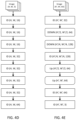
- FIG. 6 schematically depict a process for training an augmentation model according to certain embodiments of the present disclosure.
- FIG. 7 schematically depict a process for augmenting training dataset according to certain embodiments of the present disclosure.
- FIG. 8 schematically depict a process for training an object detector using the augmented training dataset according to certain embodiments of the present disclosure.
- FIG. 9 A compares performance of a DANR using high render resolution and low render resolution according to certain embodiments of the present disclosure.
- FIG. 9 B compares performance of a DANR using different training: validation data splitting ratios according to certain embodiments of the present disclosure.
- FIG. 9 C compares performance of a DANR using different backbones according to certain embodiments of the present disclosure.
- FIG. 9 D compares performance of a DANR using one stage and two-stage detection frameworks according to certain embodiments of the present disclosure.
- FIG. 9 E shows performance of a DANR using different types of datasets according to certain embodiments of the present disclosure.
- phrase at least one of A, B, and C should be construed to mean a logical (A or B or C), using a non-exclusive logical OR. It should be understood that one or more steps within a method may be executed in different order (or concurrently) without altering the principles of the present disclosure.
- module may refer to, be part of, or include an Application Specific Integrated Circuit (ASIC); an electronic circuit; a combinational logic circuit; a field programmable gate array (FPGA); a processor (shared, dedicated, or group) that executes code; other suitable hardware components that provide the described functionality; or a combination of some or all of the above, such as in a system-on-chip.
- ASIC Application Specific Integrated Circuit
- FPGA field programmable gate array
- processor shared, dedicated, or group
- the term module may include memory (shared, dedicated, or group) that stores code executed by the processor.
- code may include software, firmware, and/or microcode, and may refer to programs, routines, functions, classes, and/or objects.
- shared means that some or all code from multiple modules may be executed using a single (shared) processor. In addition, some or all code from multiple modules may be stored by a single (shared) memory.
- group means that some or all code from a single module may be executed using a group of processors. In addition, some or all code from a single module may be stored using a group of memories.
- interface generally refers to a communication tool or means at a point of interaction between components for performing data communication between the components.
- an interface may be applicable at the level of both hardware and software, and may be uni-directional or bi-directional interface.
- Examples of physical hardware interface may include electrical connectors, buses, ports, cables, terminals, and other I/O devices or components.
- the components in communication with the interface may be, for example, multiple components or peripheral devices of a computer system.
- computer components may include physical hardware components, which are shown as solid line blocks, and virtual software components, which are shown as dashed line blocks.
- virtual software components which are shown as dashed line blocks.
- these computer components may be implemented in, but not limited to, the forms of software, firmware or hardware components, or a combination thereof.
- the apparatuses, systems and methods described herein may be implemented by one or more computer programs executed by one or more processors.
- the computer programs include processor-executable instructions that are stored on a non-transitory tangible computer readable medium.
- the computer programs may also include stored data.
- Non-limiting examples of the non-transitory tangible computer readable medium are nonvolatile memory, magnetic storage, and optical storage.
- FIG. 1 is an overview of a data augmentation system 100 based on neural rendering (DANR) according to certain embodiments of the present disclosure.
- the purpose of the system 100 is to augment an object detection dataset with novel view images, and use the augmented dataset to improve performance of object detectors.
- the number of novel view images or augmented images is controllable, and degree of camera pose variations for the augmented images are also controllable.
- input of the system 100 is a labeled dataset 102 for object detection training and configurations of novel camera poses 108 .
- the labeled dataset 102 has a number of training images 104 , and each training image 104 has its corresponding annotation 106 .
- the annotation 106 for each training image 104 may include a bounding box in the image that encloses an object, and label of the object.
- the image may show a handgun, and the annotation of the image may include a bounding box in the image that encloses the handgun, as well as a label “handgun” or “weapon.”
- the novel camera poses 108 may be predefined, which may include one or multiple poses that have different variations relative to the camera poses of the images 104 .
- a neural rendering module 112 renders the images 104 at the different novel camera poses 108 to obtain new images.
- the bounding boxes of the images 104 are also rendered with the images 104 to obtain rendered bounding boxes.
- the rendered bounding boxes inherit their labels.
- the new images having the rendered bounding boxes and the labels are formatted by a formatter 114 to obtain an augmented dataset 116 .
- the augmented dataset 116 has the novel images 118 and the automatically generated annotations 120 .
- the format of the augmented dataset 116 is the same as the format of the original training dataset 102 .
- the system combines the dataset 102 and the augmented dataset 116 to obtain a new training dataset.
- the new training dataset thus includes more training data, and can be used to train object detection effectively.
- FIG. 2 schematically depicts operation of a novel view synthesis model 200 according to certain embodiments of the present disclosure.
- the novel view synthesis model corresponds to the neural rendering module 112 in FIG. 1 .
- the model takes as input a red-green-blue (RGB) image 202 (I) and annotations for bounding boxes 204 (B).
- the bounding boxes 204 are represented by a series of two-dimensional (2D) image keypoints (Bi).
- the RGB image 202 is simultaneously fed to two branches: (1) an hourglass network 206 for depth estimation (Newell, et al., Stacked hourglass networks for human pose estimation, in ECCV, 2916, which is incorporated herein by reference in its entirety), and (2) an encoder 208 with Inception-ResNet blocks to extract visual features (Ning et al., Knowledge-guided deep fractal neural network for human pose estimation, which is incorporated herein by reference in its entirety).
- the extracted visual features are pixel-aligned, i.e., each pixel on the feature maps carries a latent-space vector that corresponds to this particular spatial location.
- the depth estimation branch assigns depth value to each pixel, elevating latent space vectors to a point cloud 210 .
- Each point in the point cloud resides in a three-dimensional (3D) space with the 2.5D coordinate representation: (u, v, d) (Iqbal et al., Hand pose estimation via latent 2.5d heatmap regression, ECCV, 2018, which is incorporated herein by reference in its entirety), where u and v are 2D coordinates of the points in the point cloud, and d is the depths of the points.
- Each point may unfold its hidden N-dimensional latent-space vector after being projected to a target camera view.
- These feature vectors can be reprojected to an arbitrary camera coordinate system, based on a given projection matrix (translation vector T and rotation vector R relative to the corresponding camera of the original image).
- the camera pose of the original image is defined as P.
- the disclosure splats the feature points following Wiles's method (Wiles, et al., Synsin: End-to-end view synthesis from a single image, CVPR, 2020, which is incorporated herein by reference in its entirety) to make the rendering process differentiable.
- Wiles's method Wiles, et al., Synsin: End-to-end view synthesis from a single image, CVPR, 2020, which is incorporated herein by reference in its entirety
- these points result in an N-dimensional feature map 212 of a predefined resolution.
- the feature maps 212 are then fed to a decoder network 214 with inception-residual blocks and upsampling layers, rendering the final novel view image 216 (I′).
- the disclosure marks the keypoints of the bounding boxes beforehand.
- a novel bounding box 218 (B′) is defined and labeled automatically.
- the whole system is end-to-end differentiable.
- a novel image 220 with annotations is obtained.
- the novel image 220 and its bounding box annotations can be compared with the original image 202 and its bounding box annotations, so as to train the model.
- the annotations of the bounding boxes include both the locations of the bounding boxes and their labels.
- the locations of a bounding box may be defined by its up-left corner and lower-right corner, or by the up-left corner and the bounding box's height and width, or by a center point, the height, and the width, or any other suitable format.
- the labels of the bounding box may be the name or the type of the object in the bounding box, such as a dog.
- FIG. 3 schematically depicts an implementation of a data augmentation system 300 based on neural rendering (DANR) according to certain embodiments of the present disclosure.
- the system 300 includes a computing device 310 .
- the computing device 310 may be a server computing device, a cluster, a cloud computer, a general-purpose computer, or a specialized computer that provide training for object detection and perform object detection.
- the computing device 310 is a server of an e-commerce platform, which is configured to store training images for object detection, augment the number of the training images, train an object detection model using the augmented training images, and use the well-trained object detection model to detect objects in the e-commerce platform.
- the training images are updated regularly, and the object detection model can be re-trained regularly.
- the computing device 310 may include, without being limited to, a processor 312 , a memory 314 , and a storage device 316 .
- the computing device 310 may include other hardware components and software components (not shown) to perform its corresponding tasks. Examples of these hardware and software components may include, but not limited to, other required memory, interfaces, buses, Input/Output (I/O) modules or devices, network interfaces, and peripheral devices.
- the processor 312 may be a central processing unit (CPU) which is configured to control operation of the computing device 310 .
- the processor 312 can execute an operating system (OS) or other applications of the computing device 310 .
- OS operating system
- the computing device 310 may have more than one CPU as the processor, such as two CPUs, four CPUs, eight CPUs, or any suitable number of CPUs.
- the memory 314 can be a volatile memory, such as the random-access memory (RAM), for storing the data and information during the operation of the computing device 310 .
- the memory 314 may be a volatile memory array.
- the computing device 310 may run on more than one memory 314 .
- the storage device 316 is a non-volatile data storage media for storing the OS (not shown) and other applications of the computing device 310 .
- Examples of the storage device 316 may include non-volatile memory such as flash memory, memory cards, USB drives, hard drives, floppy disks, optical drives, solid-state drive (SSD) or any other types of data storage devices.
- the storage device 316 may be a local storage, a remote storage, or a cloud storage.
- the computing device 310 may have multiple storage devices 316 , which may be identical storage devices or different types of storage devices, and the applications of the computing device 310 may be stored in one or more of the storage devices 316 of the computing device 310 .
- the computing device 310 is a cloud computer, and the processor 312 , the memory 314 and the storage device 316 are shared resources provided over the Internet on-demand.
- the storage device 316 includes an object detection application 318 , a training dataset 350 , camera poses 360 , and augmented training dataset 370 .
- the object detection application 318 includes a data augmentation training module 320 , a data augmentation module 322 , an augmentation model 324 , an object detector training module 338 , an object detector 340 , and a user interface 342 .
- the object detection application 318 is configured to train the augmentation model 324 , use the well-trained augmentation model 324 to obtain augmented training dataset 370 from training dataset 350 , use the augmented training data 370 to train the object detector 340 , and use the well-trained object detector 340 to perform object detection on images.
- the data augmentation training module 320 is configured to instruct the augmentation model 324 to train the model, so as to obtain well-trained augmentation model 324
- the data augmentation module 322 is configured to, upon receiving notice from the augmentation model 324 that the model is well-trained, instruct the well-trained augmentation model 324 to use the training dataset 350 to obtain augmented training dataset 370 .
- the augmentation model 324 is configured to, upon receiving the instruction from the data augmentation training module 320 , perform training of the augmentation model to obtain the well-trained augmentation model, and send notice to the data augmentation module 322 that the augmentation model 324 is well-trained.
- the augmentation model 324 is further configured to, upon receiving the instruction from the data augmentation module 322 , perform data augmentation to obtain augmented training dataset 370 .
- the data augmentation training module 320 and the data augmentation module 322 may also be part of the augmentation model 324 .
- the augmentation model 324 includes a data preparation module 326 , a feature encoder 328 , a depth estimator 330 , a point cloud module 332 , a splatting module 334 , and an image decoder 336 .
- the data preparation module 326 is configured to prepare data from the training dataset 350 , and send the prepared dataset to the feature encoder 328 and the depth estimator 330 .
- each dataset of the training dataset 350 includes an image and an annotation of the image.
- the image may be a RGB image. In certain embodiments, the image may be, without being limited to, an image having a 512 ⁇ 512 resolution.
- the annotation includes location of a bounding box in the image, the bounding box encloses an object, and the annotation includes a label of the object.
- the location of the bounding box may be in any appropriate forms.
- the bounding box is defined by labeling each pixel in the bounding box.
- the bounding box is defined by a center pixel, a width of the bounding box, and a length of the bounding box.
- the bounding box is defined by four corner points of the bounding box.
- the label of the bounding box may be a category of the object, or a name of the object.
- the object is a handgun, and the label may be “handgun” or “weapon.”
- the datasets including the images and the annotations are stored in JAVASCRIPT OBJECT NOTATION (JSON) format.
- the datasets for training the augmentation model 324 and the datasets for augmentation may be different or may be the same.
- the training dataset may be updated regularly, and the augmentation model 324 may train the model after each update.
- the datasets for augmentation may be updated regularly at a predefined time interval, such as every day, every week, or every month, and the augmentation model 324 may generate updated augmented training dataset 370 after each update.
- the feature encoder 328 is configured to, upon receiving the prepared datasets from the data preparation module 326 , extract visual features from the images of the datasets, and send the visual features to the point cloud module 332 .
- the visual features are represented by feature vectors, and each of the feature vectors corresponds to one pixel in the images.
- the feature vectors have multiple dimensions, for example, 10 dimensions.
- the feature encoder 328 includes one or more inception-residual blocks, as shown in FIG. 4 D . Each inception-residual block incorporates both inception design and ResNet design, i.e., channel-wise concatenation of two branches and pixel-wise addition with an identify branch.
- FIG. 4 D Each inception-residual block incorporates both inception design and ResNet design, i.e., channel-wise concatenation of two branches and pixel-wise addition with an identify branch.
- FIG. 4 A schematically depicts an inception-residual block that maintains the resolution of features, with an identity layer
- FIG. 4 B schematically depicts an inception-residual block that increases the resolution of features, with an upsampling layer
- FIG. 4 C schematically depicts an inception-residual block that decreases the resolution of features, with an average pooling layer
- FIG. 4 D schematically depicts a feature encoder 328 stacked from the inception-residual block according to certain embodiments of the present disclosure, where ID means identity.
- the H and W in FIGS. 4 A- 4 E are height and width of the images, i.e., the resolution of the images.
- the M or the number following H and W is the number of channels.
- inception-residual blocks There are three types of inception-residual blocks: ID, UP and DOWN, as shown in FIG. 4 D and FIG. 4 E .
- ID the inception design
- UP the inception design
- DOWN the difference between the ID, UP and Down is whether the block keeps, raises, or reduces the resolution.
- the depth estimator 330 is configured to, upon receiving the prepared datasets from the data preparation module 326 , estimate depths for each pixel in each image of the datasets, and send the depths of the pixels to the point cloud module 332 .
- the depth of each pixel is represented by a value d, indicating the distance from the pixel to the camera that takes the image.
- the depth estimator 330 is an hourglass network, and this UNet-like structure is proved advantageous in terms of exploring global interdependencies across multiple scales.
- FIG. 4 F schematically depicts an architecture of the depth estimator 330 according to certain embodiments of the disclosure. Specifically, the disclosure simplifies the original hourglass network by replacing the pooling layer+ResNet blocks scheme with a down-sampling block that consists of a sequence of Leaky ReLU, convolution (stride 2 or 4, padding 1, kernel size 4), and batch normalization layers.
- An up-sampling block consists of a sequence of ReLU, a 2 ⁇ or 4 ⁇ bilinear upsampling, convolution (stride 1, padding 1, kernel size 3), and batch normalization layers.
- the Up and Down modules raise and reduce the resolution, respectively. However, they are not inception-residual blocks. Instead, they are residual blocks with pooling and up-sampling layers. Due to the complexity of the hourglass network, it is advantageous to use the residual blocks, and the risk of running out of memory during training using the inception-residual block is avoided.
- the disclosure further concatenates the output feature maps of stacked hourglass sub-networks and regress depth at the last layer (no batch normalization layer).
- the point cloud module 332 is configured to, upon receiving the visual features from the feature encoder 328 and the depths from the depth estimator 330 , form a point cloud using the visual features and the depths of the pixels, and provide the point cloud to the splatting module 334 .
- each pixel in the image corresponds to one point in the point cloud.
- Each point in the point cloud is characterized by its feature vector and its depth.
- the bounding box is defined in the image, and the feature of the bounding box is also defined in in the point cloud.
- each pixel in one bounding box may be labeled as within the bounding box, and the points in the point cloud corresponding to those pixels within the bounding box are also labeled as part of the bounding box.
- each point in the point cloud is characterized by its 2.5 D location, its feature vector, and a bounding box indicator.
- the 2.5D location of a point includes its two-dimensional coordinates and its depth, where the two-dimensional coordinates of the point are the same as the two-dimensional coordinates of the corresponding pixel in the image.
- the feature vector has multiple dimensions indicating different features of the pixel in the image, such as color, edges, or even features of neighboring pixels.
- the feature vector is learnt from the encoder network as shown in FIG. 4 D .
- the feature vector has a length of, for example, 64.
- the bounding box indicator shows whether the point in the point cloud is within the bounding box, which is consistent with whether the corresponding pixel in the image is within the bounding box.
- the splatting module 334 is configured to use the camera pose corresponding to the image in the dataset and the point cloud received from the point cloud module 332 to project the point cloud onto a predefined palette, to obtain a feature map, and send the feature map to the image decoder 336 .
- the camera pose of the image is predefined.
- the camera pose includes the intrinsic and extrinsic parameters.
- the extrinsic parameters are not used because the disclosure only needs the rotation vector R and the translation vector T from the original pose.
- the disclosure only needs the difference between the original the target pose.
- the disclosure uses predefined R and T.
- the predefined target poses or new poses include two to ten different poses.
- the number of predefined new poses is four, the four new poses share the same translation vector [0 0 0.3], and their respective rotation vectors are [ ⁇ 0.1 ⁇ 0.15 0], [0.1 ⁇ 0.15 0], [ ⁇ 0.1 0.15 0], [0.1 0.15 0].
- the translation vector and rotation vector together determine the projection matrix, as shown in FIG. 5 B .
- the image decoder 336 is configured to, upon receiving the feature map, decode the feature map to obtain a target image, calculate a loss based on the difference between the original image from the training dataset 350 and the corresponding target image, and adjust parameters of the augmentation model 324 .
- FIG. 4 E schematically depicts a decoder structure according to certain embodiments of the present disclosure, which is stacked by inception-residual blocks.
- the decoder structure can be used with the encoder shown in FIG. 4 D , and the decoder structure may correspond to the function of the splatting module 334 and the image decoder 336 .
- ID means Identity
- Up is upsampling
- Down is downsampling by average pooling.
- the resolution of input features of the Decoder is by default identical to the features extracted by the Encoder shown in FIG. 4 D .
- the 3D points 2.5D points
- the feature map is upsampled by the scale of 2, which will uplift the image render resolution.
- the disclosure refers to this super-resolution method as PointSS, in contrast to PixelSS where the rendered images are fed to an external super-resolution network.
- the point projection by the splatting module 334 and the image decoder 336 is performed as follows.
- the disclosure fixes the intrinsic parameters for all images, assuming they are taken with a default camera. Specifically, the disclosure sets focal lengths on both x and y axes to be 1 and set skew to be 0, while assuming principal point is at the origin of coordinates. Given a 2.5D point representation, the disclosure maps it to the Camera Coordinate System (CCS) of the input image:
- CCS Camera Coordinate System
- each bounding box i points (at least the four points at corners) are marked with an index value i. These marked keypoints are a subset of S ⁇ S points, where S is the resolution of the extracted feature maps.
- P′ i ⁇ (u′ i , v′ i ) ⁇ .
- the corresponding points can be named bounding box point.
- the corresponding projected pixels can be named bounding box pixels.
- the bounding box pixels in the target image can then be used to define the projected bounding box in the target image.
- the projected bounding box can be labeled the same way as the bounding in the original image. By this way, the projected bounding box can be determined easily and labeled directly without any object detection process.
- the projected bounding box and the bounding box in the original image may be slightly different.
- corner pixels in the bounding box in the original image and the corner pixels in the projected bounding box may be different, due to the pixel movement during the projection process. Further, some pixels in the bounding box in the image may also be missed in the target image due to different camera view angle.
- the loss function for training the augmentation model 324 is as follows.
- the present disclosure follows Ning (Ning et al, Knowledge-guided deep fractal neural networks for human pose estimation, IEEE transactions on multimedia, 2018, V20(5), 1246-1259, which is incorporated herein by reference by its entirety) for the discriminator design, and use two multi-layer discriminators, the one with lower resolution serving as intermediate supervision to help the one with higher resolution learn better and faster.
- the overall loss is consisted of image-level L1 loss, feature-level content loss and discriminator loss.
- the training of the augmentation model 324 may be performed using batches of training datasets, where each batch may include for example 10-100 images and their annotations. In certain embodiments, the training of the augmentation model 324 may be performed for a predetermined times using the same set of training dataset 350 .
- the splatting module 334 is configured to use the predefined camera poses 360 to project one point cloud to the predefined palette to obtain multiple feature maps
- the image decoder 336 is configured to decode the multiple feature maps to multiple target images, and combine the target images with bounding box annotations and the original images with bounding box annotations to form the augmented training dataset 370 .
- the camera poses 360 includes four different camera poses, and each original training image would result in four target images. Accordingly, the number of datasets in the final augmented training dataset 370 is five times the number of datasets in the training dataset 350 .
- 3D cloud points in the new view are sorted in depth using a z-buffer.
- the nearest point in depth is chosen to color that point.
- the disclosure follows the differentiable renderer in order to provide gradients with respect to the point cloud positions.
- K nearest points for each pixel are splatted; each of these points influences a range that originates from the splatted pixel with radius r, the influence of which is proportional to the Euclidean distance from the center.
- the sorted points are then accumulated using linear alpha over-compositing. In this way, the hard z-buffer becomes differentiable.
- An example of the differentiable renderer is shown in FIG. 5 A .
- two points from the z-buffer are splatted onto a palette with an influence range of radius 3 .
- the object detector training module 338 is configured to, when the augmented training dataset 370 is obtained, using the augmented training dataset 370 to train the object detector 340 .
- the object detector 340 is configured to, when being well-trained by the object detector training module 338 , process images provided by the ecommerce platform to obtain objects in the images, obtain annotation of the objects, and report the image and its annotation if the annotation meet certain criteria.
- the object detector 340 is configured to use a keypoint-based object detection.
- Keypoint estimation is naturally a regression problem.
- the targets are represented by a series of heatmaps, each channel corresponding to a specific keypoint genre.
- Recent object detection methods such as CenterNet, CornerNet and ExtremeNet, begin to utilize keypoint estimation techniques.
- CenterNet transforms the task of object detection from generating and classifying proposals into predicting objects centers (keypoints) and corresponding attributes.
- the attributes are the width, height of the object, along with local offsets that recover pixel location in the original resolution from down-sampled heatmaps.
- the disclosure uses CenterNet as baseline detection framework to conduct experiments and ablation studies, due to its simplicity.
- NMS non-maximum suppression
- keypoint-based mixed up is used for object detection by the object detector 340 . It is first demonstrated in Inoue (Inoue, Data augmentation by paring samples for images classification, arXiv:1801.02929, 2018) how mixing samples up could be developed into an effective augmentation strategy. Image mixup for the task of object detection has been described in Zhang (Zhang et al., Bag of freebies for training object device detection neural networks, arXiv:1902.04103, 2019), but it is restricted to bounding box mixup. In certain embodiments, the present disclosure designs a straight-forward image mixup strategy for keypoint-based object detection methods, where ground truth keypoints are splat onto a heatmap
- ⁇ p is an adaptive standard deviation that is proportional to the size of the object.
- the user interface 342 is configured to provide a user interface or graphic user interface in the computing device 310 .
- the user or the administrator of the system is able to configure parameters for the modules in the object detection application 318 .
- the training dataset 350 includes dataset for training the augmentation model 324 or for being used by the augmentation model 324 to generate the augmented training dataset 370 .
- the training dataset 350 includes images and labels of the images.
- the label for each image may include a bounding box enclosing an object in the image, and a category of the object.
- the training dataset 350 may also include the camera poses for taking the images.
- the camera poses 360 includes definition of camera poses used by the augmentation model 324 to generate augmented training database 370 .
- the camera poses are relative poses in regard to the original camera pose of the image, and each camera pose defined by the camera poses 360 is used to generate one augmented image.
- the camera poses 360 are defined such that they are distant from each other. The distribution of the camera poses at different view angles improves quality of the augmented training dataset 370 .
- the number of camera poses 360 is in a range of 2-10. In certain embodiments, the number of camera poses 360 is four.
- FIG. 5 B schematically depicts four camera poses 360 . As shown in FIG. 5 B , the camera poses 360 are defined by rotation and translation relative to the original camera pose. In certain embodiments, the original camera poses can be derived based on intrinsic and extrinsic parameters of cameras of training images.
- the augmented training dataset 370 are generated by the augmentation model 324 based on the training dataset 350 and the camera poses 360 .
- the augmentation model 324 for each training image from the training dataset 350 , the augmentation model 324 generate the number of new images corresponding to the number of camera poses 360 , and then combine the original training images and the new images, together with the annotations, to form the augmented training dataset 370 .
- modules in the object detection application 318 may process each of the images one by one, or process the images by batches, and the images in each batch may be processed in parallel.
- FIG. 6 schematically depict a process 600 for training the augmentation model according to certain embodiments of the present disclosure.
- the training process is performed by a computing device, such as the computing device 310 shown in FIG. 3 , and specifically by the augmentation model 324 .
- the steps of the training process may be arranged in a different sequential order, and are thus not limited to the sequential order as shown in FIG. 6 .
- the date augmentation training module 320 calls the training of the augmentation model 324 .
- the data preparation module 326 prepares the training dataset 350 , and sends the prepared training dataset to the feature encoder 328 and the depth estimator 330 .
- the prepared training dataset 350 includes multiple training samples, each training sample includes an image and its annotation.
- the annotation includes a definition of a bounding box enclosing an object in the image, and the identification of the object.
- the definition of the bounding box may include the center, the width and the length of the bounding box.
- the definition of the bounding box may be a labeled character of the pixels of the images, where the labeled character may be inside or outside the bounding box.
- the identification of the object may be the category of the object or the name of the object.
- the training dataset 350 is prepared in advance manually. In certain embodiments, the training dataset 350 is further expanded automatically by incorporating new images and their labels filtered out in an ecommerce platform. In certain embodiments, the training of the augmentation model 324 is performed using batches of training dataset. In certain embodiments, each batch of training dataset includes 5-50 different training samples. In certain embodiments, the number of training samples in each batch is eight.
- the training samples are arranged by pairs, and the disclosure takes a pair of adjacent frames (images) for each back-propagation.
- the adjacent images has a distance/interval ranging from 0.5 second to 1 second, and the two images are of the same scene but in slightly different angles.
- the two images in the pair is named first image I and second image I′.
- the ground truth contains their corresponding camera poses.
- the disclosure calculates rotation vector R and translation vector T from the first image I to the second image I′ based on their camera poses, and calculates projection matrix P based on the rotation vector R and translation vector T.
- each pixel in the first image I is represented by a visual vector.
- each visual vector has, for example, 100 dimensions.
- one of the dimensions or an additional feature for each pixel exits, and the dimension or the additional feature indicates whether it is inside or outside the bounding box.
- the depth estimator 330 estimates depths for each pixel in the first image I, and sends the depths of the pixels to the point cloud module 332 .
- the point cloud module 332 combines the information for the first image I to form a point cloud for that image, and sends the point cloud to the splatting module 334 .
- the point cloud includes points, each point corresponds to a pixel in the original image I.
- Each point has a two-dimensional coordinates (u, v) and a depth d, has a label indicating whether the point is within the bounding box or not, and has the visual vector corresponding to the feature of the pixel, where the feature includes color, edges, etc.
- the splatting module 334 uses the projection matrix P, projects the points of the point cloud to a predefined palette to obtain a feature map, and sends the feature map to the image decoder 336 .
- the points having the character of within the bounding box or outside the bounding box is also transferred to the feature map.
- the disclosure chooses the first image I as the input image, and projects the points of its point cloud using the projection matrix P to obtain the corresponding feature map.
- the image decoder 336 decodes the feature map to form a target image I′′.
- the target image I′′ includes definition of the target bounding box.
- each pixel in the target image has a character of within the bounding box or outside the bounding box, which is transferred from the feature map.
- the image decoder 336 further compares the target image I′′ with the second image I′ to calculate a loss, and adjusts parameters of the augmentation model 324 based on the loss by back-propagation.
- the disclosure may also project the firs image based on its own camera pose (using projection matrix [0 0 0]) to obtain a target image, calculate the loss by comparing the target image with the first image, and back-propagate based on the loss.
- the training process may be performed again using another pair of training samples from the training dataset, until the parameters converge, or until a predetermined times of training iterations are completed, or until the training is performed using a predefined number of images.
- the disclosure uses a batch of multiple pair of images. Using batch of pairs instead of one pair speeds up the training process, and averages the errors.
- each batch may include eight pairs of images, the eight pairs of images can be processed by, for example a graphic processing unit (GPU) in parallel, the forward propagation in the batch can be averaged; then at the end of the procession of the batch, parameters are adjusted and back propagation is performed.
- the disclosure retrieves another batch to perform another iteration of the training.
- the training dataset includes continuous video frames (images), and each of the pair of images may be selected from the videos.
- the selection of one pair of images may be performed by: selecting a frame (image) i from a randomly picked video, and searching a frame in the N number of frames following the frame i, where N is a positive integer, such as 15.
- the searching may be performed by: selecting a frame from the 15 frames, calculating the rotation and translation matrix of the selected frame relative to the frame i, and the selected frame is determined to form the pair with the frame i when the rotation between the frames is greater than 5 degrees and the translation between the frames is greater than 0.15.
- the selection of the frame may be performed one by one from the first of the 15 frames to the last of the 15 frames until a frame meeting the above criteria is found.
- the disclosure may also calculate the rotation and translation matrix for the 15 frames in parallel, and randomly selecting one of the frames that meets the above criteria.
- the well-trained model 324 can be used to augment the training dataset 350 to generate augmented training dataset 370 .
- the training dataset used for training the augmentation model 324 and the training dataset used for generating the augmented training dataset 370 may be different datasets, or may be the same datasets.
- a portion of the training dataset 350 is used to train the augmentation model 324 , and the rest of the training dataset 350 is used for generating the augmented training dataset 370 .
- FIG. 7 schematically depict a process 700 for augmenting training dataset according to certain embodiments of the present disclosure.
- the augmentation process is performed by a computing device, such as the computing device 310 shown in FIG. 3 , and specifically by the augmentation model 324 .
- the steps of the training process may be arranged in a different sequential order, and are thus not limited to the sequential order as shown in FIG. 7 .
- the date augmentation module 322 calls the augmentation model 324 to augment training dataset.
- the data preparation module 326 prepares the training dataset 350 , and sends the prepared training dataset to the feature encoder 328 and the depth estimator 330 .
- the prepared training dataset 350 includes multiple datasets, each dataset includes an image and its annotation.
- the annotation includes a definition of a bounding box enclosing an object in the image, and the identification of the object.
- each pixel in one of the images is represented by a visual vector.
- each visual vector has, for example, 100 dimensions.
- one of the dimensions or an additional feature for each pixel corresponds to the bounding box, where each pixel is indicated a pixel inside the bounding box or a pixel outside the bounding box.
- the depth estimator 330 estimates depths for each pixel in each of the images, and sends the depths of the pixels to the point cloud module 332 .
- the point cloud module 332 combines the information for each image to form a point cloud for that image, and sends the point cloud to the splatting module 334 .
- the procedures 704 - 708 are substantially the same as the procedures 606 - 610 , except that the augmentation model 324 has been well trained at this time, and the prepared datasets may include more data.
- the splatting module 334 retrieves the camera poses 360 (specifically the projection matrix), projects the points of the point cloud to a predefined palette using the projection matrix to obtain feature maps, and sends the feature maps to the image decoder 336 .
- Each feature map corresponds to one of the camera poses 360 . If there are four new poses, then there would be four generated feature maps for each of the images.
- the image decoder 336 decodes the feature maps to form target images.
- Each target image corresponds to one of the feature maps.
- the target image includes definition of the target bounding box.
- the image decoder 336 further combines the target images, the annotations of the target images, and the corresponding original image and its annotation, to form the augmented training dataset 370 .
- the model would generate four new target images. Accordingly, for each original image, there would be five images with their annotations, which correspond to the one original image and the four new images.
- FIG. 8 schematically depict a process 800 for training an object detector using the augmented training dataset according to certain embodiments of the present disclosure.
- the training process is performed by a computing device, such as the computing device 310 shown in FIG. 3 , and specifically by the object detector training module 338 .
- the steps of the training process may be arranged in a different sequential order, and are thus not limited to the sequential order as shown in FIG. 8 .
- the object detector training module 338 trains the object detector 340 using the augmented training dataset 370 .
- the training may be performed iteratively until parameters of the object detector 340 converge.
- the object detection application 318 retrieves images for detection, use the object detector 340 to detect objects from the retrieved images.
- the detection result may include one or more bounding boxes in the retrieved images, each bounding box encloses an object in one of the retrieved images, and the object is labeled with an identification, such as the category or the name of the object.
- the images are automatically retrieved by the object detector 340 from the ecommerce platform, such as new product images, or images from new forum posts.
- the object detector 340 further provides a warning message when certain categories or names are detected from the retrieved images, and sends the warning message to an intended administrator or user.
- the object detector 340 has a CenterNet structure.
- an RGB image is inputted and the output includes multiple heatmaps or channels, each heatmap corresponds to an object, such as weapons, cigarette, or flag.
- a threshold value such as 0.5
- the present disclosure relates to a non-transitory computer readable medium storing computer executable code.
- the computer executable code may be the software stored in the storage device 316 as described above.
- the computer executable code when being executed, may perform the methods described above.
- the detection performance is significantly improved.
- the small render resolution e.g. 256 ⁇ 256
- the detector input resolution e.g., 512 ⁇ 512.
- FIG. 9 A compares performance of the DANR using high render resolution and low render resolution, where the dataset is an indoor validation set, AP means average precision, N.A.
- APs indicates AP for small image size
- AP M indicates AP for medium image size
- APL indicates AP for large image size.
- we use 512-native as our resolution setting, as it achieves the highest AP and does not need any additional super-sampling networks.
- the performance of DANR on datasets with different data scarcity is evaluation.
- the experiment is performed with three data-split settings: 5:5, 3:7 and 1:9. Highest degree of scarcity is 1:9.
- Each image is augmented with four synthesized images. While splitting images to train and validation sets, an image is assigned along with its corresponding augmented images.
- FIG. 9 B compares performance of the DANR using different training: validation data splitting ratios, where the dataset is an indoor validation set. As shown in FIG. 9 B , the performance boost is closely related with the scarcity of training data. When annotated data is very limited, the DANR approach becomes more beneficial.
- backbone for DANR is optimized.
- FIG. 9 C compares performance of the DANR using different backbones including ResNet-50 and ResNeSt-50, where the dataset is an indoor validation set. As shown in FIG. 9 C , the proposed augmentation consistently boost the detection performance, regardless of the backbones used by the detector.
- DANR application of DANR on one-stage and two-stage detection frameworks are evaluated.
- CenterNet as an example of one-stage method, while using Hit-Detector to represent the two-stage approach.
- Hit-Detector we use the official code release of Hit-Detector to perform training and testing.
- FIG. 9 D DANR does not rely on the one-stage detection framework. It is beneficial to two-stage detectors as well.
- results on various datasets are shown in FIG. 9 E .
- FIG. 9 E (1) Results on image content review datasets (ICR-Weapon, ICR-Flag and ICR-Logo) show that the DANR is consistently helpful on real-world data when training data is scarce; (2) Results on indoor dataset show that the augmentation is highly beneficial with indoor data, even when training data is not scarce; (3) Results on COCO dataset have shown that DANR makes little contribution under circumstances where (a) the neural renderer in DANR fails to fully generalize to the semantics of the particular dataset, and (b) the training data is abundant.
- certain embodiments of the present disclosure provides a new method of data augmentation for object detection based on differentiable neural rendering.
- neural rendering offers a more promising generative modeling technique for use in data augmentation, as it bridges the 2D and 3D domain, and offers highly controllable ways to manipulate images.
- the bounding box definition and labeling are maintained or projected, such that the rendered new images also include bounding box information.
- the rendered new images and the bounding box information for the new images can be used directly as training dataset for object detection.
Landscapes
- Engineering & Computer Science (AREA)
- Theoretical Computer Science (AREA)
- Physics & Mathematics (AREA)
- General Physics & Mathematics (AREA)
- Computer Vision & Pattern Recognition (AREA)
- Evolutionary Computation (AREA)
- Data Mining & Analysis (AREA)
- Artificial Intelligence (AREA)
- Multimedia (AREA)
- Life Sciences & Earth Sciences (AREA)
- General Engineering & Computer Science (AREA)
- Computing Systems (AREA)
- Health & Medical Sciences (AREA)
- Software Systems (AREA)
- General Health & Medical Sciences (AREA)
- Evolutionary Biology (AREA)
- Bioinformatics & Cheminformatics (AREA)
- Bioinformatics & Computational Biology (AREA)
- Medical Informatics (AREA)
- Databases & Information Systems (AREA)
- Biomedical Technology (AREA)
- Biophysics (AREA)
- Computational Linguistics (AREA)
- Molecular Biology (AREA)
- Mathematical Physics (AREA)
- Image Analysis (AREA)
Abstract
Description
-
- provide a two-dimensional (2D) image and a projection camera pose, wherein the 2D image comprises a bounding box, the bounding box encloses an object, and the bounding box is annotated according to the object;
- extract feature vectors of pixels in the 2D image, each pixel having a corresponding feature vector;
- estimate depths of the pixels from the 2D image;
- generate a point cloud using the feature vectors and the depths of the pixels; and
- project the point cloud to obtain a projected image using the projection camera pose,
- where each of the pixels within the bounding box has a bounding box label and is named bounding box pixel, each point in the point cloud corresponding to the bounding box pixel has the bounding box label and is named bounding box point, each image pixel in the projected image corresponding to the bounding box point has the bounding box label and is named projected bounding box pixel, and a projected bounding box is defined using the projected bounding box pixels.
wherein (u, v) is coordinate of a target point in the point cloud, d is depth of the target point in the point cloud, cx and cy are bias of a center of the camera, fx and fy are focal lengths on x and y axes of the camera, and (Xc, Yc, Zc) are coordinates of the target point in the camera coordinate system. In certain embodiments, the computer executable code is configured to compare the projected image with the 2D image to learn parameters for extracting the feature keypoints, estimating the depths, generating the point cloud, and projecting the point cloud.
wherein P′i={(u′i,v′i)} are coordinates of pixels in the projected bounding box.
-
- providing, by a computing device, a two-dimensional (2D) image and a projection camera pose, wherein the 2D image comprises a bounding box, the bounding box encloses an object, and the bounding box is annotated according to the object;
- extracting, by the computing device, feature vectors of pixels in the 2D image, each pixel having a corresponding feature vector;
- estimating, by the computing device, depths of the pixels from the 2D image;
- generating, by the computing device, a point cloud using the feature vectors and the depths of the pixels; and
- projecting, by the computing device, the point cloud to obtain a projected image using the projection camera pose,
- where each of the pixels within the bounding box has a bounding box label and is named bounding box pixel, each point in the point cloud corresponding to the bounding box pixel has the bounding box label and is named bounding box point, each pixel in the projected image corresponding to the bounding box point has the bounding box label and is named projected bounding box pixel, and a projected bounding box is defined using the projected bounding box pixels.
wherein (u, v) is coordinate of a target point in the point cloud, d is depth of the point in the point cloud, cx and cy are bias of a center of the camera, fx and fy are focal lengths on x and y axes of the camera, and (Xc, Yc, Zc) are coordinates of the target point in the camera coordinate system. In certain embodiments, the method further includes comparing the projected image with the 2D image to learn parameters for extracting the feature vectors, estimating the depths, generating the point cloud, and projecting the point cloud.
wherein Pi={(u′i,v′i} are coordinates of pixels in the projected bounding box.
P c =R·(P w −T) (2)
-
- where Pc=)
using a Gaussian kernel:
Claims (20)
Priority Applications (2)
| Application Number | Priority Date | Filing Date | Title |
|---|---|---|---|
| US17/327,745 US12019706B2 (en) | 2021-05-23 | 2021-05-23 | Data augmentation for object detection via differential neural rendering |
| CN202210284952.5A CN114627173B (en) | 2021-05-23 | 2022-03-22 | Data Augmentation for Object Detection via Differential Neural Rendering |
Applications Claiming Priority (1)
| Application Number | Priority Date | Filing Date | Title |
|---|---|---|---|
| US17/327,745 US12019706B2 (en) | 2021-05-23 | 2021-05-23 | Data augmentation for object detection via differential neural rendering |
Publications (2)
| Publication Number | Publication Date |
|---|---|
| US20220383041A1 US20220383041A1 (en) | 2022-12-01 |
| US12019706B2 true US12019706B2 (en) | 2024-06-25 |
Family
ID=81903563
Family Applications (1)
| Application Number | Title | Priority Date | Filing Date |
|---|---|---|---|
| US17/327,745 Active 2042-08-24 US12019706B2 (en) | 2021-05-23 | 2021-05-23 | Data augmentation for object detection via differential neural rendering |
Country Status (2)
| Country | Link |
|---|---|
| US (1) | US12019706B2 (en) |
| CN (1) | CN114627173B (en) |
Cited By (1)
| Publication number | Priority date | Publication date | Assignee | Title |
|---|---|---|---|---|
| US20240169698A1 (en) * | 2022-11-23 | 2024-05-23 | Logitech Europe S.A. | Object detection using artificial intelligence |
Families Citing this family (11)
| Publication number | Priority date | Publication date | Assignee | Title |
|---|---|---|---|---|
| US11769227B2 (en) * | 2021-08-12 | 2023-09-26 | Adobe Inc. | Generating synthesized digital images utilizing a multi-resolution generator neural network |
| US12014508B2 (en) * | 2021-10-18 | 2024-06-18 | Ford Global Technologies, Llc | Distance determination from image data |
| EP4546249A4 (en) | 2022-10-24 | 2025-10-29 | Samsung Electronics Co Ltd | METHOD AND ELECTRONIC DEVICE FOR TRAINING A NEURAL NETWORK MODEL BY AUGMENTATION OF IMAGES CAPTURED BY MULTIPLE CAMERAS |
| CN116703774B (en) * | 2023-06-20 | 2025-11-28 | 中国科学院软件研究所 | Video defogging method and device based on three-dimensional point cloud matching and real scene reconstruction |
| CN116843808B (en) * | 2023-06-30 | 2024-06-18 | 北京百度网讯科技有限公司 | Rendering, model training and virtual image generating method and device based on point cloud |
| CN117115804B (en) * | 2023-08-23 | 2025-12-16 | 华中科技大学 | Weak-semi-supervised three-dimensional point cloud target detection method and device based on visual transducer |
| CN116977810B (en) * | 2023-09-25 | 2024-01-09 | 之江实验室 | Multi-modal post-fusion long-tail category detection method and system |
| KR20250062738A (en) * | 2023-10-31 | 2025-05-08 | 삼성전자주식회사 | Method and apparatus for data augmentation |
| CN117911626B (en) * | 2024-01-31 | 2024-07-12 | 中南大学 | Building boundary polygon construction method and system based on laser point cloud data |
| DE102024209842A1 (en) | 2024-10-09 | 2026-04-09 | Aumovio Autonomous Mobility Germany Gmbh | Method for generating a training dataset based on camera images |
| CN119904374B (en) * | 2025-03-28 | 2025-07-22 | 科大讯飞股份有限公司 | Image enhancement method, device, electronic device and storage medium |
Citations (9)
| Publication number | Priority date | Publication date | Assignee | Title |
|---|---|---|---|---|
| US20160065903A1 (en) * | 2014-08-27 | 2016-03-03 | Metaio Gmbh | Method and system for providing at least one image captured by a scene camera of a vehicle |
| US20170039756A1 (en) * | 2015-08-07 | 2017-02-09 | Christie Digital Systems Usa, Inc. | System and method for automatic alignment and projection mapping |
| US20180075602A1 (en) * | 2016-09-09 | 2018-03-15 | Adobe Systems Incorporated | Planar region guided 3d geometry estimation from a single image |
| US20190362186A1 (en) * | 2018-05-09 | 2019-11-28 | Figure Eight Technologies, Inc. | Assisted image annotation |
| US20200250453A1 (en) * | 2019-01-31 | 2020-08-06 | Adobe Inc. | Content-aware selection |
| US20210134048A1 (en) * | 2019-11-05 | 2021-05-06 | Institute For Information Industry | Computer device and method for generating synthesized depth map |
| US20210158139A1 (en) * | 2019-11-21 | 2021-05-27 | Adobe Inc. | Methods and systems for geometry-aware image contrast adjustments via image-based ambient occlusion estimation |
| US20210166367A1 (en) * | 2019-11-28 | 2021-06-03 | Kwangwoon University Industry-Academic Collaboration Foundation | Method and apparatus for realtime object detection in unmanned aerial vehicle image |
| US20210264659A1 (en) * | 2020-02-24 | 2021-08-26 | Adobe Inc. | Learning hybrid (surface-based and volume-based) shape representation |
Family Cites Families (6)
| Publication number | Priority date | Publication date | Assignee | Title |
|---|---|---|---|---|
| EP3857451A4 (en) * | 2018-09-25 | 2022-06-22 | Matterport, Inc. | USING THREE-DIMENSIONAL DATA PREDICTED FROM TWO-DIMENSIONAL IMAGES USING NEURAL NETWORKS FOR 3D MODELING APPLICATIONS |
| US11100646B2 (en) * | 2019-09-06 | 2021-08-24 | Google Llc | Future semantic segmentation prediction using 3D structure |
| CN110689008A (en) * | 2019-09-17 | 2020-01-14 | 大连理工大学 | Monocular image-oriented three-dimensional object detection method based on three-dimensional reconstruction |
| CN111583390B (en) * | 2020-04-28 | 2023-05-02 | 西安交通大学 | Three-dimensional semantic graph reconstruction method of convolutional neural network based on depth semantic fusion |
| CN111739005B (en) * | 2020-06-22 | 2023-08-08 | 北京百度网讯科技有限公司 | Image detection method, device, electronic device and storage medium |
| CN112700552B (en) * | 2020-12-31 | 2025-06-27 | 华为技术有限公司 | Three-dimensional object detection method, device, electronic equipment and medium |
-
2021
- 2021-05-23 US US17/327,745 patent/US12019706B2/en active Active
-
2022
- 2022-03-22 CN CN202210284952.5A patent/CN114627173B/en active Active
Patent Citations (9)
| Publication number | Priority date | Publication date | Assignee | Title |
|---|---|---|---|---|
| US20160065903A1 (en) * | 2014-08-27 | 2016-03-03 | Metaio Gmbh | Method and system for providing at least one image captured by a scene camera of a vehicle |
| US20170039756A1 (en) * | 2015-08-07 | 2017-02-09 | Christie Digital Systems Usa, Inc. | System and method for automatic alignment and projection mapping |
| US20180075602A1 (en) * | 2016-09-09 | 2018-03-15 | Adobe Systems Incorporated | Planar region guided 3d geometry estimation from a single image |
| US20190362186A1 (en) * | 2018-05-09 | 2019-11-28 | Figure Eight Technologies, Inc. | Assisted image annotation |
| US20200250453A1 (en) * | 2019-01-31 | 2020-08-06 | Adobe Inc. | Content-aware selection |
| US20210134048A1 (en) * | 2019-11-05 | 2021-05-06 | Institute For Information Industry | Computer device and method for generating synthesized depth map |
| US20210158139A1 (en) * | 2019-11-21 | 2021-05-27 | Adobe Inc. | Methods and systems for geometry-aware image contrast adjustments via image-based ambient occlusion estimation |
| US20210166367A1 (en) * | 2019-11-28 | 2021-06-03 | Kwangwoon University Industry-Academic Collaboration Foundation | Method and apparatus for realtime object detection in unmanned aerial vehicle image |
| US20210264659A1 (en) * | 2020-02-24 | 2021-08-26 | Adobe Inc. | Learning hybrid (surface-based and volume-based) shape representation |
Non-Patent Citations (3)
| Title |
|---|
| A. Tewari, O. Fried, et al., State of the art on neural rendering, arXiv, 2020, arXiv:2004.03805. |
| Connor Shorten, and Taghi Khoshgoftaar, A survey on image data augmentation for deep learning, Journal of Big Data, 2019, 6(1), 60. |
| Ming-Yu Liu, Xun Huang, Jiahui Yu, Ting-Chun Wang, Arun Mallya, Generative adversarial networks for Image and video synthesis: algorithms and applications, arXiv, 2020, arXiv:2008.02793. |
Cited By (1)
| Publication number | Priority date | Publication date | Assignee | Title |
|---|---|---|---|---|
| US20240169698A1 (en) * | 2022-11-23 | 2024-05-23 | Logitech Europe S.A. | Object detection using artificial intelligence |
Also Published As
| Publication number | Publication date |
|---|---|
| CN114627173B (en) | 2025-04-15 |
| US20220383041A1 (en) | 2022-12-01 |
| CN114627173A (en) | 2022-06-14 |
Similar Documents
| Publication | Publication Date | Title |
|---|---|---|
| US12019706B2 (en) | Data augmentation for object detection via differential neural rendering | |
| Žbontar et al. | Stereo matching by training a convolutional neural network to compare image patches | |
| EP3576017B1 (en) | Method and system for determining pose of object in image, and storage medium | |
| Huang et al. | Salicon: Reducing the semantic gap in saliency prediction by adapting deep neural networks | |
| US20210398294A1 (en) | Video target tracking method and apparatus, computer device, and storage medium | |
| CN112750133B (en) | Computer vision training system and method for training a computer vision system | |
| Eigen et al. | Depth map prediction from a single image using a multi-scale deep network | |
| US10353271B2 (en) | Depth estimation method for monocular image based on multi-scale CNN and continuous CRF | |
| dos Santos Rosa et al. | Sparse-to-continuous: Enhancing monocular depth estimation using occupancy maps | |
| EP3836083A1 (en) | Disparity estimation system and method, electronic device and computer program product | |
| US12586335B2 (en) | Systems and methods for reconstructing a three-dimensional object from an image | |
| US11875490B2 (en) | Method and apparatus for stitching images | |
| GB2547760A (en) | Method of image processing | |
| Ghosh et al. | Two-stage cross-fusion network for stereo event-based depth estimation | |
| EP4350632A2 (en) | Method and appratus with neural rendering based on view augmentation | |
| CN116977548A (en) | Three-dimensional reconstruction method, device, equipment and computer-readable storage medium | |
| US20250265781A1 (en) | Method and system for recovering a three-dimensional human mesh in camera space | |
| Sundaram et al. | FSSCaps-DetCountNet: fuzzy soft sets and CapsNet-based detection and counting network for monitoring animals from aerial images | |
| Zhou et al. | A lightweight object detection framework for underwater imagery with joint image restoration and color transformation | |
| Zhang et al. | Panoptic-level image-to-image translation for object recognition and visual odometry enhancement | |
| Zhang et al. | Gamed-snake: Gradient-aware adaptive momentum evolution deep snake model for multi-organ segmentation | |
| Cao et al. | A yolov8-based lightweight detection model for different perspectives infrared images | |
| Wietrzykowski et al. | Stereo plane R-CNN: Accurate scene geometry reconstruction using planar segments and camera-agnostic representation | |
| Lie et al. | Efficient 6DoF pose estimation for multi-instance objects from a single image | |
| Zhang | Integrating Panoptic-Level to Image Translation |
Legal Events
| Date | Code | Title | Description |
|---|---|---|---|
| AS | Assignment |
Owner name: JD FINANCE AMERICA CORPORATION, DELAWARE Free format text: ASSIGNMENT OF ASSIGNORS INTEREST;ASSIGNORS:NING, GUANGHAN;LUO, SI;BO, LIEFENG;AND OTHERS;SIGNING DATES FROM 20210510 TO 20210523;REEL/FRAME:056321/0776 Owner name: JINGDONG DIGITS TECHNOLOGY HOLDING CO., LTD., CHINA Free format text: ASSIGNMENT OF ASSIGNORS INTEREST;ASSIGNORS:NING, GUANGHAN;LUO, SI;BO, LIEFENG;AND OTHERS;SIGNING DATES FROM 20210510 TO 20210523;REEL/FRAME:056321/0776 |
|
| STPP | Information on status: patent application and granting procedure in general |
Free format text: DOCKETED NEW CASE - READY FOR EXAMINATION |
|
| STPP | Information on status: patent application and granting procedure in general |
Free format text: NON FINAL ACTION MAILED |
|
| STPP | Information on status: patent application and granting procedure in general |
Free format text: RESPONSE TO NON-FINAL OFFICE ACTION ENTERED AND FORWARDED TO EXAMINER |
|
| AS | Assignment |
Owner name: JINGDONG TECHNOLOGY HOLDING CO., LTD., CHINA Free format text: ASSIGNMENT OF ASSIGNORS INTEREST;ASSIGNORS:JINGDONG DIGITS TECHNOLOGY HOLDING CO., LTD.;JD FINANCE AMERICA CORPORATION;REEL/FRAME:066226/0981 Effective date: 20240119 |
|
| STPP | Information on status: patent application and granting procedure in general |
Free format text: NOTICE OF ALLOWANCE MAILED -- APPLICATION RECEIVED IN OFFICE OF PUBLICATIONS |
|
| STPP | Information on status: patent application and granting procedure in general |
Free format text: PUBLICATIONS -- ISSUE FEE PAYMENT VERIFIED |
|
| STCF | Information on status: patent grant |
Free format text: PATENTED CASE |