US12017240B2 - Efficient spray applicator for universal usage - Google Patents
Efficient spray applicator for universal usage Download PDFInfo
- Publication number
- US12017240B2 US12017240B2 US16/647,954 US201816647954A US12017240B2 US 12017240 B2 US12017240 B2 US 12017240B2 US 201816647954 A US201816647954 A US 201816647954A US 12017240 B2 US12017240 B2 US 12017240B2
- Authority
- US
- United States
- Prior art keywords
- applicator
- flat panel
- panel body
- spray
- rim
- Prior art date
- Legal status (The legal status is an assumption and is not a legal conclusion. Google has not performed a legal analysis and makes no representation as to the accuracy of the status listed.)
- Active
Links
- 239000007921 spray Substances 0.000 title claims abstract description 75
- 230000003044 adaptive effect Effects 0.000 claims 2
- 238000007373 indentation Methods 0.000 claims 1
- 239000012530 fluid Substances 0.000 description 14
- 239000007788 liquid Substances 0.000 description 9
- 238000005507 spraying Methods 0.000 description 9
- 239000000463 material Substances 0.000 description 8
- 238000004040 coloring Methods 0.000 description 5
- 239000000443 aerosol Substances 0.000 description 4
- 239000003795 chemical substances by application Substances 0.000 description 4
- 239000003086 colorant Substances 0.000 description 3
- 238000004891 communication Methods 0.000 description 3
- 238000012986 modification Methods 0.000 description 3
- 230000004048 modification Effects 0.000 description 3
- 241000271566 Aves Species 0.000 description 2
- 230000006978 adaptation Effects 0.000 description 2
- 239000006071 cream Substances 0.000 description 2
- 238000013461 design Methods 0.000 description 2
- 230000037308 hair color Effects 0.000 description 2
- 238000010348 incorporation Methods 0.000 description 2
- 239000000203 mixture Substances 0.000 description 2
- 239000003973 paint Substances 0.000 description 2
- 238000010422 painting Methods 0.000 description 2
- 210000004761 scalp Anatomy 0.000 description 2
- 239000008257 shaving cream Substances 0.000 description 2
- TUSDEZXZIZRFGC-UHFFFAOYSA-N 1-O-galloyl-3,6-(R)-HHDP-beta-D-glucose Natural products OC1C(O2)COC(=O)C3=CC(O)=C(O)C(O)=C3C3=C(O)C(O)=C(O)C=C3C(=O)OC1C(O)C2OC(=O)C1=CC(O)=C(O)C(O)=C1 TUSDEZXZIZRFGC-UHFFFAOYSA-N 0.000 description 1
- 239000001263 FEMA 3042 Substances 0.000 description 1
- LRBQNJMCXXYXIU-PPKXGCFTSA-N Penta-digallate-beta-D-glucose Natural products OC1=C(O)C(O)=CC(C(=O)OC=2C(=C(O)C=C(C=2)C(=O)OC[C@@H]2[C@H]([C@H](OC(=O)C=3C=C(OC(=O)C=4C=C(O)C(O)=C(O)C=4)C(O)=C(O)C=3)[C@@H](OC(=O)C=3C=C(OC(=O)C=4C=C(O)C(O)=C(O)C=4)C(O)=C(O)C=3)[C@H](OC(=O)C=3C=C(OC(=O)C=4C=C(O)C(O)=C(O)C=4)C(O)=C(O)C=3)O2)OC(=O)C=2C=C(OC(=O)C=3C=C(O)C(O)=C(O)C=3)C(O)=C(O)C=2)O)=C1 LRBQNJMCXXYXIU-PPKXGCFTSA-N 0.000 description 1
- 238000005452 bending Methods 0.000 description 1
- 230000015572 biosynthetic process Effects 0.000 description 1
- 230000000903 blocking effect Effects 0.000 description 1
- 239000000969 carrier Substances 0.000 description 1
- 230000008859 change Effects 0.000 description 1
- 238000012505 colouration Methods 0.000 description 1
- 230000001276 controlling effect Effects 0.000 description 1
- 230000002596 correlated effect Effects 0.000 description 1
- 239000006260 foam Substances 0.000 description 1
- XEEYBQQBJWHFJM-UHFFFAOYSA-N iron Substances [Fe] XEEYBQQBJWHFJM-UHFFFAOYSA-N 0.000 description 1
- 229910052742 iron Inorganic materials 0.000 description 1
- -1 iron ions Chemical class 0.000 description 1
- 238000000034 method Methods 0.000 description 1
- 239000002245 particle Substances 0.000 description 1
- 229920000642 polymer Polymers 0.000 description 1
- 239000006041 probiotic Substances 0.000 description 1
- 235000018291 probiotics Nutrition 0.000 description 1
- 238000007592 spray painting technique Methods 0.000 description 1
- 239000000758 substrate Substances 0.000 description 1
- LRBQNJMCXXYXIU-NRMVVENXSA-N tannic acid Chemical compound OC1=C(O)C(O)=CC(C(=O)OC=2C(=C(O)C=C(C=2)C(=O)OC[C@@H]2[C@H]([C@H](OC(=O)C=3C=C(OC(=O)C=4C=C(O)C(O)=C(O)C=4)C(O)=C(O)C=3)[C@@H](OC(=O)C=3C=C(OC(=O)C=4C=C(O)C(O)=C(O)C=4)C(O)=C(O)C=3)[C@@H](OC(=O)C=3C=C(OC(=O)C=4C=C(O)C(O)=C(O)C=4)C(O)=C(O)C=3)O2)OC(=O)C=2C=C(OC(=O)C=3C=C(O)C(O)=C(O)C=3)C(O)=C(O)C=2)O)=C1 LRBQNJMCXXYXIU-NRMVVENXSA-N 0.000 description 1
- 229940033123 tannic acid Drugs 0.000 description 1
- 235000015523 tannic acid Nutrition 0.000 description 1
- 229920002258 tannic acid Polymers 0.000 description 1
Images


Classifications
-
- B—PERFORMING OPERATIONS; TRANSPORTING
- B65—CONVEYING; PACKING; STORING; HANDLING THIN OR FILAMENTARY MATERIAL
- B65D—CONTAINERS FOR STORAGE OR TRANSPORT OF ARTICLES OR MATERIALS, e.g. BAGS, BARRELS, BOTTLES, BOXES, CANS, CARTONS, CRATES, DRUMS, JARS, TANKS, HOPPERS, FORWARDING CONTAINERS; ACCESSORIES, CLOSURES, OR FITTINGS THEREFOR; PACKAGING ELEMENTS; PACKAGES
- B65D83/00—Containers or packages with special means for dispensing contents
- B65D83/14—Containers for dispensing liquid or semi-liquid contents by internal gaseous pressure, i.e. aerosol containers comprising propellant
- B65D83/28—Nozzles, nozzle fittings or accessories specially adapted therefor
- B65D83/30—Nozzles, nozzle fittings or accessories specially adapted therefor for guiding the flow of the dispensed content, e.g. funnels or hoods
-
- A—HUMAN NECESSITIES
- A45—HAND OR TRAVELLING ARTICLES
- A45D—HAIRDRESSING OR SHAVING EQUIPMENT; EQUIPMENT FOR COSMETICS OR COSMETIC TREATMENTS, e.g. FOR MANICURING OR PEDICURING
- A45D44/00—Other cosmetic or toiletry articles, e.g. for hairdressers' rooms
-
- B—PERFORMING OPERATIONS; TRANSPORTING
- B05—SPRAYING OR ATOMISING IN GENERAL; APPLYING FLUENT MATERIALS TO SURFACES, IN GENERAL
- B05B—SPRAYING APPARATUS; ATOMISING APPARATUS; NOZZLES
- B05B12/00—Arrangements for controlling delivery; Arrangements for controlling the spray area
- B05B12/16—Arrangements for controlling delivery; Arrangements for controlling the spray area for controlling the spray area
- B05B12/32—Shielding elements, i.e. elements preventing overspray from reaching areas other than the object to be sprayed
- B05B12/36—Side shields, i.e. shields extending in a direction substantially parallel to the spray jet
-
- B—PERFORMING OPERATIONS; TRANSPORTING
- B65—CONVEYING; PACKING; STORING; HANDLING THIN OR FILAMENTARY MATERIAL
- B65D—CONTAINERS FOR STORAGE OR TRANSPORT OF ARTICLES OR MATERIALS, e.g. BAGS, BARRELS, BOTTLES, BOXES, CANS, CARTONS, CRATES, DRUMS, JARS, TANKS, HOPPERS, FORWARDING CONTAINERS; ACCESSORIES, CLOSURES, OR FITTINGS THEREFOR; PACKAGING ELEMENTS; PACKAGES
- B65D83/00—Containers or packages with special means for dispensing contents
- B65D83/14—Containers for dispensing liquid or semi-liquid contents by internal gaseous pressure, i.e. aerosol containers comprising propellant
Definitions
- the present invention relates to a spray applicator, and more particularly, to a spray applicator for efficient spraying of paint and/or coloring agents on non-round surfaces.
- the spray applicator has specific embodiments attached either on the outer frame of the round top of the container or inside the top for specific spraying.
- Spray applicators are utilized for a variety of uses and purposes in real world. Most of these applicators embody adjustable spray applicators for varying or changing the direction from or location to which fluid from an attached nozzle needs to be sprayed.
- These spray applicators sprays various types of fluid, including paints, or different coloring agents in bursts of various geometric patterns.
- nozzles determine the application volume at a given operating pressure, travel speeds, and spacing that break the liquid into droplets and form the spray pattern. It determines the amount of spray volume at a given operating pressure, travel speed, and spacing. Drift can be minimized by selecting nozzles that produce the largest droplet size while providing adequate coverage at the intended application rate and pressure. Selecting nozzles that produce the largest droplet size, while providing adequate coverage at the intended application rate and pressure, can minimize drift.
- the size of the spray particle is important because it affects both efficacy and spray drift of the application. All the spray applicators use conventional nozzles that entail inefficiency in their spray formation thus necessitating their modifications, which is attempted in the present invention.
- the present sprayer nozzles available in the market are conical in shape and hence, cone nozzles yields complete spray coverage in a round or oval shape.
- This type of colouring is perfect, if the surface on which it is to be sprayed is round. But if the liquid or the color to be sprayed is on a non round surface, then the present applicators have specific disadvantages.
- the application of colour becomes difficult since the sprayed colour may spill into the area which is either not required to be coloured or a different colouration is required.
- This can be applicable in case of colouring hair (non round surface) or any such surface which is not round in the edges.
- the colours usually gets spilled over to the scalp as well, which can be avoided by using the applicator of the present invention.
- U.S. Pat. No. 8,316,863 B2 titled “Applicator nozzle and applicator assembly incorporating such a nozzle” discloses an applicator using teeth in a comb shape is expensive to produce and lack efficiency since it sprays to close to the hair.
- the applicator nozzle comprises an attachment portion configured to attach the nozzle to a receptacle configured to contain a product and an arrangement of at least two teeth disposed so as to form at least one row comprising first and second end teeth.
- US20110005538 A1 titled “Agents, compositions and devices for temporary coloring local hair areas” discloses hair-coloring applicators comprising a shield to protect the scalp, polymers of tannic acid having iron ions bound thereto, hair-coloring compositions comprising same and/or melanoidin, and novel alcohol-free carriers, are disclosed, as well uses thereof for coloring hair.
- U.S. Pat. No. 3,302,235A titled “Applicator attachment for aerosol shaving cream container” discloses an applicator attachment for aerosol shaving cream. the applicator is used there to help spread the cream and is of a round shape thus it could't be used for material that is not a foam or cream and could't be used for bordering the application of a sprayed material/
- WO 2016187548 A1 titled, “Inline avian spray applicator with rapidly-actuating automatic spray nozzles” relates to spray applicator devices and methods of use for vaccinating, or administering probiotics to avian animals.
- Said automated spray applicator device comprises a housing, at least one rapidly actuatable automatic spray nozzle, a programmable spray module, for controlling the automatic spray nozzle(s), and optionally a source of pressurized air for supplying pressure to the fluid prior to its entry into the spray nozzles; wherein the programmable spray module is in electrical, pneumatic or hydraulic connection with the at least one automatic spray nozzle; wherein the automatic spray nozzle(s) is(are) in fluid communication with a fluid reservoir/tank; and wherein the automatic spray nozzle comprises an electrical, pneumatic or hydraulic actuator and a nozzle tip.
- the spray nozzle comprising a tip housing and a valve.
- the tip housing has a distal end, a proximal end, and a lumen that extends between the ends and defines a lengthwise central axis.
- the valve has an elongated body that extends through the lumen of the tip housing, along the lengthwise central axis.
- the valve being configured to slide within the lumen of the tip housing, in an extended position with respect therewith is configured to disperse the medicinal agent toward the tissue. When the valve is in the retracted position with respect to the tip housing, the medicinal agent is vented away from the tissue.
- U.S. Pat. No. 8,303,531 B2 titled, “Spray applicator with positionable spray tip” discusses an apparatus for applying a spray to a selected site on a patient includes a sheath having a through bore extending from a first end to a second end.
- a flexible multi-lumen tube is secured within the sheath and has a distal portion that extends beyond the second end of the sheath.
- a malleable wire is positioned within at least the distal portion of the multi-lumen tube wherein manual force is exerted upon the distal portion to position the distal end in a selected position by bending the malleable wire.
- a housing is attached to the rigid outer sheath and has a plurality of ports for engaging a multi-tube syringe and a port for injecting a gas into the selected site wherein each port is in communication with at least one lumen.
- a spray nozzle is removably attached to the distal end of the multi-lumen tube wherein the at least one liquid and the gas are discharged from the multi-lumen tube and into the spray nozzle such that the aerosol exiting the spray nozzle is effective in treating the selected site.
- U.S. Pat. No. 5,129,356 A titled “Fluid applicator” talks of an applicator for applying multiple lines of a fluid to a substrate includes a manifold having a plurality of fluid flow passages with a like plurality of spaced apart fluid outlets and at least one fluid inlet. Fluid spray nozzles are attached to the manifold in fluid flow communication with the fluid outlets of the manifold.
- the manifold further includes a swivel mounting for allowing the manifold to pivot about an axis parallel to the spray axes of the spray nozzles.
- Another object of the present invention is to develop a novel spray applicator that is designed to be at an angle in accordance with the angle of the out-coming spray to enable spray pattern in a semi-circular/semi elliptical shape for painting of straight edge.
- Still another object of the invention is to incorporate an applicator, having its application edge, shaped in a variety of ways to enable spraying and giving a differently shaped edge to the applied burst of colour in accordance with the requirement of the surface of the sprayed object.
- Another object of the invention is the incorporation of an embodiment that allows the flat nozzle to be elevated at different spray angles to enable spray painting of different tops in the most optimum manner. Different angles of elevation of the applicator allow different spray-burst admissible to a typical surface.
- Another object of the invention is the incorporation of flat-fan nozzles at several spray angles of 65, 73, 80, and 110 degrees to enable even spray pattern aligned properly on the sprayed surface.
- Still another object of the invention is to allow the nozzle to be rotated about ten degrees from the axis of the boom to prevent droplets of adjacent nozzles from touching but still allowing for proper overlap of the spray pattern.
- the correct nozzle height is measured from the nozzle to the target, which may be the top of the ground, growing canopy, or stubble.
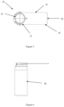
- FIG. 1 illustrates the isometric view of the sprayed material on to the object in prior art using the simple sprayer.
- FIG. 2 illustrates the side view of the sprayed material on to the object in prior art using the simple sprayer.
- FIG. 3 illustrates the isometric view of the sprayed material on to the object using the applicator of the present invention, fitted to the sprayer.
- FIG. 4 illustrates the side view of the sprayed material on to the object using the applicator of the present invention, fitted to the sprayer.
- FIG. 5 illustrates the top view of the applicator mounted on the outer surface of the sprayer of the present invention.
- FIG. 6 illustrates the side view of the applicator mounted on the outer surface of the sprayer of the present invention.
- FIG. 7 illustrates the front view of the applicator mounted on the outer surface of the sprayer of the present invention.
- FIG. 8 illustrates the isometric view of the applicator mounted on the outer surface of the sprayer of the present invention.
- FIG. 9 is a technical illustration of the top view of the applicator for mounting on the outer surface of the sprayer of the present invention.
- FIG. 10 is a technical illustration of an enlarged view of detail A of the applicator for mounting on the outer surface of the sprayer of the present invention.
- FIG. 11 is a technical illustration of the applicator in its side view for mounting on the outer surface of the sprayer of the present invention.
- FIG. 12 is a technical illustration of the applicator in its front view for mounting on the outer surface of the sprayer of the present invention.
- FIG. 13 is a technical illustration of the applicator from its bottom for mounting on the outer surface of the sprayer of the present invention.
- FIG. 14 is an isometric view from top of the applicator for mounting on the outer surface of the sprayer of the present invention.
- FIG. 15 is an isometric view from side of the applicator for mounting on the outer surface of the sprayer of the present invention
- FIG. 16 illustrates the top view of the applicator mounted on the inner surface of the sprayer of the present invention.
- FIG. 17 illustrates the side view of the applicator mounted on the inner surface of the sprayer of the present invention.
- FIG. 18 illustrates the front view of the applicator mounted on the inner surface of the sprayer of the present invention.
- FIG. 19 illustrates the isometric view of the applicator mounted on the inner surface of the sprayer of the present invention.
- FIG. 20 is a technical illustration of the top view of the applicator for mounting on the inner surface of the sprayer of the present invention.
- FIG. 21 is a technical illustration of an enlarged view of detail A of the applicator for mounting on the inner surface of the sprayer of the present invention.
- FIG. 22 is a technical illustration of the applicator in its side view for mounting on the inner surface of the sprayer of the present invention
- FIG. 23 is an isometric view of the applicator for mounting on the inner surface of the sprayer of the present invention.
- FIG. 24 is a technical illustration of the applicator in its front view for mounting on the inner surface of the sprayer of the present invention.
- FIG. 25 is a technical illustration of the applicator from its bottom for mounting on the inner surface of the sprayer of the present invention.
- FIG. 26 is an isometric view of the applicator for mounting on the inner surface of the sprayer of the present invention.
- FIG. 27 illustrates the isometric view of the folded applicator mounted on the inner surface of the sprayer of the present invention.
- FIG. 28 illustrates the isometric view of the folded applicator mounted on the inner surface of the sprayer of the present invention with the applicator folded at 90 degree angle.
- FIG. 29 illustrates the isometric view of the foldable applicator of the present invention.
- FIG. 30 is a side view of the foldable applicator.
- FIGS. 8 and 14 illustrates the isometric view of an applicator ( 10 ) for spray application having a flat panel body ( 12 ) having a proximal end ( 14 ) and a distal end ( 16 ).
- the said proximal end ( 14 ) of the said flat panel body ( 12 ) is structured as a connector in a circular shape forming a rim ( 22 ) having an inner surface ( 24 ) and an outer surface ( 26 ), wherein, the said inner surface ( 24 ) of the said rim ( 22 ) functions as a connector to be fitted perfectly with the lid of a universal sprayer ( 28 ).
- the said rim ( 22 ) of the connector is extended downwards to form a skirt ( 30 ) having a width of 10.30 mm like the lid of a container without the top surface.
- the circular rimmed structure of the connector helps in mounting it with the outer surface of the lid of the sprayer as is depicted in FIG. 8 .
- the said circular rim along with the skirting can further be divided into a major arc portion ( 32 ), from where the said flat panel shaped applicator structure extends for spray application, whereas the minor arc portion ( 34 ) positioned diametrically opposite to the said applicator is left open, for easy adaptability with any sprayer bottle.
- the edge ( 20 ) of the distal end of the flat panel body is straight.
- the other two side edges ( 18 ), ( 18 ′) of the panel are also straight and are devoid of any corrugations and design.
- the thickness of the flat panel body ( 12 ) is maintained at 0.76 mm. It will be known to those skilled in the art, that the width of the said flat panel, and the angle at which the spraying needs to be done are correlated. In the present embodiment the width is maintained at 36.70 mm.
- the radius of the inner surface ( 24 ) of the circular rim ( 22 ) of the proximal end of the panel is maintained at 15.02 mm and the radius of the outer surface ( 26 ) of the said circular rim ( 22 ) of the connector of the proximal end of the panel is maintained at 20.21 mm.
- the opening of the said minor arc ( 34 ) of the said circular rim ( 22 ), which lies diametrically opposite to the said applicator ( 10 ), is maintained at 20 mm.
- the length of the said flat panel connector from the end of the nozzle at the distal end of the applicator till the centre of the circular rim (connector) of the applicator at the proximal end measures 86.80 mm.
- the total length of the applicator measuring from the tip of the distal end of the applicator is maintained at 103.55 mm as is illustrated in FIG. 13 .
- the length of the applicator will depend upon the object on which the liquid has to be sprayed, the type and purpose of spraying. Hence the length of the applicator can be varied accordingly.
- the extended skirting of the said rim is provided with gaps ( 36 ) at intervals, which gives it broad tooth like structure ( 38 ) to be adapted to be fitted with the inner surface of the lid of the sprayer.
- the radius of the said inner surface ( 24 ) of the said circular rim of the said proximal end ( 14 ) of the panel is maintained at 10.10 mm and the radius of the outer surface ( 26 ) of the said circular rim of the connector of the proximal end of the panel is maintained at 13.95 mm.
- the opening of the minor arc ( 34 ) of the said circular rim ( 22 ), which lies diametrically opposite to the said applicator, is maintained at 10 mm.
- the length of the flat panel from the end of the nozzle at the distal end of the applicator till the centre of the circular rim of the connector of the applicator at the proximal end measures 86.80 mm.
- the total length of the applicator measuring from the tip of the distal end of the applicator is maintained at 99.65 mm.
- the length of the applicator will depend upon the object on which the liquid has to be sprayed, the type and purpose of spraying. Hence the length of the applicator can be varied accordingly.
- the sprayer of the prior art applicators usually sprays the liquid in the form of an elliptical shape on the surface to be sprayed, which is perfect, if the surface on which it is to be sprayed is round. But if the liquid or the color to be sprayed is on a non round surface, then the applicator of the prior art has specific disadvantages.
- an angled applicator with edges of the applicator variously designed is proposed, which sprays the liquid as desired on the surface with a straight edge or edges shaped differently also prevents spilling of the sprayed material.
- an angled applicator is provided in this embodiment.
- the flat panel applicator is designed to have an angle which is provided at a short distance from the proximal end of the applicator as shown in FIGS. 22 - 23 and FIG. 24 .
- the designing of the applicator at an angle from the circular rim of the applicator prevents blocking of the sprayed material.
- FIG. 27 through FIG. 30 an embodiment of the present invention is shown, wherein the applicator can be folded at 90 degrees with respect to the nozzle of the sprayer or the connector of the applicator.
- the provision of an axle present at a short distance from the proximal end of the applicator helps the applicator to be folded.
- the edge of the distal end of the applicator is variable depending upon the texture or type of surface to which the spray is to be applied.
- the edge of the distal end of the applicator is designed in a wavy form.
- This design is attained by an alternate concave ( 40 ) and convex ( 42 ) arrangement of the arcs, the radius of each arc being 1.20 mm.
- Each consecutive concave ( 40 ) or convex arc ( 42 ) is equidistant from each other.
- the distance from the centre of each concave or convex arc with respect to the next concave or convex arc is 3.40 mm. Further the width between the crest and trough of the curves is maintained at 0.65 mm for optimized spraying function
- the edge of the distal end of the panel of the applicator is designed to form triangles, thereby providing it with pointed like structure.
Landscapes
- Chemical & Material Sciences (AREA)
- Dispersion Chemistry (AREA)
- Engineering & Computer Science (AREA)
- Mechanical Engineering (AREA)
- Containers And Packaging Bodies Having A Special Means To Remove Contents (AREA)
Abstract
Description
-
- 10 applicator
- 12 Flat panel body
- 14 proximal end
- 16 distal end
- 18, 18′ side edges
- 20 distal edge
- 22 rim
- 24 inner surface
- 26 outer surface
- 28 sprayer
- 30 skirt
- 32 major arc
- 34 minor arc
- 36 gap
- 38 tooth
- 40 concave arc
- 42 convex arc
Claims (16)
Applications Claiming Priority (3)
| Application Number | Priority Date | Filing Date | Title |
|---|---|---|---|
| IL254703 | 2017-09-26 | ||
| IL254703A IL254703B2 (en) | 2017-09-26 | 2017-09-26 | An efficient spray applicator for universal usage |
| PCT/IL2018/051048 WO2019064295A1 (en) | 2017-09-26 | 2018-09-17 | An efficient spray applicator for universal usage |
Publications (2)
| Publication Number | Publication Date |
|---|---|
| US20200246824A1 US20200246824A1 (en) | 2020-08-06 |
| US12017240B2 true US12017240B2 (en) | 2024-06-25 |
Family
ID=61837924
Family Applications (1)
| Application Number | Title | Priority Date | Filing Date |
|---|---|---|---|
| US16/647,954 Active US12017240B2 (en) | 2017-09-26 | 2018-09-17 | Efficient spray applicator for universal usage |
Country Status (3)
| Country | Link |
|---|---|
| US (1) | US12017240B2 (en) |
| IL (1) | IL254703B2 (en) |
| WO (1) | WO2019064295A1 (en) |
Citations (8)
| Publication number | Priority date | Publication date | Assignee | Title |
|---|---|---|---|---|
| US3302235A (en) | 1965-01-11 | 1967-02-07 | Gerber Boris | Applicator attachment for aerosol shaving cream container |
| DE8109756U1 (en) * | 1982-09-09 | Lang, Ludwig, Dipl.-Ing. | Spray can with device for influencing the fog jet | |
| WO1985002829A1 (en) | 1983-12-17 | 1985-07-04 | Nitzsche, Klaus | Protection screen for sprayers |
| US5070819A (en) | 1991-02-21 | 1991-12-10 | Fred Helmstetter | Pet comb for attachment to spray can |
| US20160107185A1 (en) * | 2014-10-21 | 2016-04-21 | William C. Smith | Attachment for a spraying device for use in small places with evacuation of particulates |
| US20160194140A1 (en) * | 2014-06-27 | 2016-07-07 | Westrock Dispensing Systems, Inc. | Dual actuated aerosol devices |
| US20160221744A1 (en) * | 2015-01-29 | 2016-08-04 | Tremco Illbruck Productie B.V. | Dispenser head |
| US20200095054A1 (en) * | 2017-09-21 | 2020-03-26 | Randy M. Pindor | Spray can actuator |
-
2017
- 2017-09-26 IL IL254703A patent/IL254703B2/en unknown
-
2018
- 2018-09-17 WO PCT/IL2018/051048 patent/WO2019064295A1/en not_active Ceased
- 2018-09-17 US US16/647,954 patent/US12017240B2/en active Active
Patent Citations (8)
| Publication number | Priority date | Publication date | Assignee | Title |
|---|---|---|---|---|
| DE8109756U1 (en) * | 1982-09-09 | Lang, Ludwig, Dipl.-Ing. | Spray can with device for influencing the fog jet | |
| US3302235A (en) | 1965-01-11 | 1967-02-07 | Gerber Boris | Applicator attachment for aerosol shaving cream container |
| WO1985002829A1 (en) | 1983-12-17 | 1985-07-04 | Nitzsche, Klaus | Protection screen for sprayers |
| US5070819A (en) | 1991-02-21 | 1991-12-10 | Fred Helmstetter | Pet comb for attachment to spray can |
| US20160194140A1 (en) * | 2014-06-27 | 2016-07-07 | Westrock Dispensing Systems, Inc. | Dual actuated aerosol devices |
| US20160107185A1 (en) * | 2014-10-21 | 2016-04-21 | William C. Smith | Attachment for a spraying device for use in small places with evacuation of particulates |
| US20160221744A1 (en) * | 2015-01-29 | 2016-08-04 | Tremco Illbruck Productie B.V. | Dispenser head |
| US20200095054A1 (en) * | 2017-09-21 | 2020-03-26 | Randy M. Pindor | Spray can actuator |
Non-Patent Citations (3)
| Title |
|---|
| PCT Preliminary Report on Patentability for Patent Application No. PCT/IL2018/051048, dated Mar. 31, 2020, 6 pp. |
| PCT Search Report for International Patent Application No. PCT/IL2018/051048, dated Jan. 20, 2019, 3 pp. |
| PCT Written Opinion for International Patent Application No. PCT/IL2018/051048, dated Jan. 20, 2019, 5 pp. |
Also Published As
| Publication number | Publication date |
|---|---|
| IL254703B1 (en) | 2023-12-01 |
| IL254703B2 (en) | 2024-04-01 |
| WO2019064295A1 (en) | 2019-04-04 |
| IL254703A0 (en) | 2017-11-30 |
| US20200246824A1 (en) | 2020-08-06 |
Similar Documents
| Publication | Publication Date | Title |
|---|---|---|
| EP1296578B1 (en) | Spray head | |
| MXPA06014808A (en) | Fluid atomizing system and method. | |
| KR102265854B1 (en) | Method and apparatus for spraying ground surfaces | |
| CA2623056C (en) | Multiple discharge orifice spray nozzle | |
| WO2020050945A1 (en) | Multi-orifice nozzle for droplet atomization | |
| US12017240B2 (en) | Efficient spray applicator for universal usage | |
| US20040031499A1 (en) | Fluid dispensing brush | |
| US4494699A (en) | Adjustable spray nozzle | |
| JP2022541773A (en) | Low-drift, high-efficiency spraying system | |
| CN111050926B (en) | Dispensing device for spraying sprayable media | |
| NZ290739A (en) | Dispensing nozzle having a head with nozzles of different lengths | |
| CA3137917C (en) | Wide angle spray nozzle | |
| EP2136928B1 (en) | Reversible air-assisted airless spray tip | |
| AU9432298A (en) | Atomizer foil, atomizer having such an atomizer foil and use of such atomizer foil | |
| BR112021021365B1 (en) | SPRAYING NOZZLE AND DEVICE | |
| CN209914872U (en) | Pesticide spraying device for forestry disease and pest control | |
| SU884647A1 (en) | Liquid sprayer | |
| AU704711B2 (en) | Dispensing nozzle | |
| HK40019134A (en) | Dispensing device for spraying a sprayable medium | |
| HK40019134B (en) | Dispensing device for spraying a sprayable medium | |
| NZ210066A (en) | Atomiser entrains liquid over blown wing |
Legal Events
| Date | Code | Title | Description |
|---|---|---|---|
| STPP | Information on status: patent application and granting procedure in general |
Free format text: APPLICATION DISPATCHED FROM PREEXAM, NOT YET DOCKETED |
|
| STPP | Information on status: patent application and granting procedure in general |
Free format text: DOCKETED NEW CASE - READY FOR EXAMINATION |
|
| STPP | Information on status: patent application and granting procedure in general |
Free format text: NON FINAL ACTION MAILED |
|
| STCB | Information on status: application discontinuation |
Free format text: ABANDONED -- FAILURE TO RESPOND TO AN OFFICE ACTION |
|
| STPP | Information on status: patent application and granting procedure in general |
Free format text: FINAL REJECTION MAILED |
|
| STPP | Information on status: patent application and granting procedure in general |
Free format text: DOCKETED NEW CASE - READY FOR EXAMINATION |
|
| STPP | Information on status: patent application and granting procedure in general |
Free format text: NON FINAL ACTION MAILED |
|
| STPP | Information on status: patent application and granting procedure in general |
Free format text: RESPONSE TO NON-FINAL OFFICE ACTION ENTERED AND FORWARDED TO EXAMINER |
|
| STPP | Information on status: patent application and granting procedure in general |
Free format text: NOTICE OF ALLOWANCE MAILED -- APPLICATION RECEIVED IN OFFICE OF PUBLICATIONS |
|
| ZAAB | Notice of allowance mailed |
Free format text: ORIGINAL CODE: MN/=. |
|
| STPP | Information on status: patent application and granting procedure in general |
Free format text: PUBLICATIONS -- ISSUE FEE PAYMENT VERIFIED |
|
| STCF | Information on status: patent grant |
Free format text: PATENTED CASE |