US12012009B2 - Autonomous charging systems for battery powered transport refrigeration units - Google Patents
Autonomous charging systems for battery powered transport refrigeration units Download PDFInfo
- Publication number
- US12012009B2 US12012009B2 US17/385,322 US202117385322A US12012009B2 US 12012009 B2 US12012009 B2 US 12012009B2 US 202117385322 A US202117385322 A US 202117385322A US 12012009 B2 US12012009 B2 US 12012009B2
- Authority
- US
- United States
- Prior art keywords
- landing gear
- reefer
- battery
- trailer
- leg
- Prior art date
- Legal status (The legal status is an assumption and is not a legal conclusion. Google has not performed a legal analysis and makes no representation as to the accuracy of the status listed.)
- Active, expires
Links
- 238000005057 refrigeration Methods 0.000 title description 4
- 238000000034 method Methods 0.000 claims abstract description 15
- 230000008878 coupling Effects 0.000 claims abstract description 4
- 238000010168 coupling process Methods 0.000 claims abstract description 4
- 238000005859 coupling reaction Methods 0.000 claims abstract description 4
- 239000002184 metal Substances 0.000 description 2
- 230000003466 anti-cipated effect Effects 0.000 description 1
- 238000004590 computer program Methods 0.000 description 1
- 230000003203 everyday effect Effects 0.000 description 1
- 230000006698 induction Effects 0.000 description 1
- 230000035939 shock Effects 0.000 description 1
- 230000007704 transition Effects 0.000 description 1
Images


Classifications
-
- B—PERFORMING OPERATIONS; TRANSPORTING
- B62—LAND VEHICLES FOR TRAVELLING OTHERWISE THAN ON RAILS
- B62D—MOTOR VEHICLES; TRAILERS
- B62D33/00—Superstructures for load-carrying vehicles
- B62D33/04—Enclosed load compartments ; Frameworks for movable panels, tarpaulins or side curtains
- B62D33/048—Enclosed load compartments ; Frameworks for movable panels, tarpaulins or side curtains for refrigerated goods vehicles
-
- B—PERFORMING OPERATIONS; TRANSPORTING
- B60—VEHICLES IN GENERAL
- B60L—PROPULSION OF ELECTRICALLY-PROPELLED VEHICLES; SUPPLYING ELECTRIC POWER FOR AUXILIARY EQUIPMENT OF ELECTRICALLY-PROPELLED VEHICLES; ELECTRODYNAMIC BRAKE SYSTEMS FOR VEHICLES IN GENERAL; MAGNETIC SUSPENSION OR LEVITATION FOR VEHICLES; MONITORING OPERATING VARIABLES OF ELECTRICALLY-PROPELLED VEHICLES; ELECTRIC SAFETY DEVICES FOR ELECTRICALLY-PROPELLED VEHICLES
- B60L53/00—Methods of charging batteries, specially adapted for electric vehicles; Charging stations or on-board charging equipment therefor; Exchange of energy storage elements in electric vehicles
- B60L53/10—Methods of charging batteries, specially adapted for electric vehicles; Charging stations or on-board charging equipment therefor; Exchange of energy storage elements in electric vehicles characterised by the energy transfer between the charging station and the vehicle
- B60L53/14—Conductive energy transfer
- B60L53/16—Connectors, e.g. plugs or sockets, specially adapted for charging electric vehicles
-
- B—PERFORMING OPERATIONS; TRANSPORTING
- B60—VEHICLES IN GENERAL
- B60L—PROPULSION OF ELECTRICALLY-PROPELLED VEHICLES; SUPPLYING ELECTRIC POWER FOR AUXILIARY EQUIPMENT OF ELECTRICALLY-PROPELLED VEHICLES; ELECTRODYNAMIC BRAKE SYSTEMS FOR VEHICLES IN GENERAL; MAGNETIC SUSPENSION OR LEVITATION FOR VEHICLES; MONITORING OPERATING VARIABLES OF ELECTRICALLY-PROPELLED VEHICLES; ELECTRIC SAFETY DEVICES FOR ELECTRICALLY-PROPELLED VEHICLES
- B60L53/00—Methods of charging batteries, specially adapted for electric vehicles; Charging stations or on-board charging equipment therefor; Exchange of energy storage elements in electric vehicles
- B60L53/30—Constructional details of charging stations
- B60L53/35—Means for automatic or assisted adjustment of the relative position of charging devices and vehicles
-
- B—PERFORMING OPERATIONS; TRANSPORTING
- B60—VEHICLES IN GENERAL
- B60S—SERVICING, CLEANING, REPAIRING, SUPPORTING, LIFTING, OR MANOEUVRING OF VEHICLES, NOT OTHERWISE PROVIDED FOR
- B60S9/00—Ground-engaging vehicle fittings for supporting, lifting, or manoeuvring the vehicle, wholly or in part, e.g. built-in jacks
- B60S9/02—Ground-engaging vehicle fittings for supporting, lifting, or manoeuvring the vehicle, wholly or in part, e.g. built-in jacks for only lifting or supporting
- B60S9/04—Ground-engaging vehicle fittings for supporting, lifting, or manoeuvring the vehicle, wholly or in part, e.g. built-in jacks for only lifting or supporting mechanically
- B60S9/06—Ground-engaging vehicle fittings for supporting, lifting, or manoeuvring the vehicle, wholly or in part, e.g. built-in jacks for only lifting or supporting mechanically of screw-and-nut type
- B60S9/08—Ground-engaging vehicle fittings for supporting, lifting, or manoeuvring the vehicle, wholly or in part, e.g. built-in jacks for only lifting or supporting mechanically of screw-and-nut type the screw axis being substantially vertical
-
- B—PERFORMING OPERATIONS; TRANSPORTING
- B62—LAND VEHICLES FOR TRAVELLING OTHERWISE THAN ON RAILS
- B62D—MOTOR VEHICLES; TRAILERS
- B62D53/00—Tractor-trailer combinations; Road trains
- B62D53/04—Tractor-trailer combinations; Road trains comprising a vehicle carrying an essential part of the other vehicle's load by having supporting means for the front or rear part of the other vehicle
- B62D53/08—Fifth wheel traction couplings
- B62D53/0857—Auxiliary semi-trailer handling or loading equipment, e.g. ramps, rigs, coupling supports
-
- Y—GENERAL TAGGING OF NEW TECHNOLOGICAL DEVELOPMENTS; GENERAL TAGGING OF CROSS-SECTIONAL TECHNOLOGIES SPANNING OVER SEVERAL SECTIONS OF THE IPC; TECHNICAL SUBJECTS COVERED BY FORMER USPC CROSS-REFERENCE ART COLLECTIONS [XRACs] AND DIGESTS
- Y02—TECHNOLOGIES OR APPLICATIONS FOR MITIGATION OR ADAPTATION AGAINST CLIMATE CHANGE
- Y02T—CLIMATE CHANGE MITIGATION TECHNOLOGIES RELATED TO TRANSPORTATION
- Y02T10/00—Road transport of goods or passengers
- Y02T10/60—Other road transportation technologies with climate change mitigation effect
- Y02T10/70—Energy storage systems for electromobility, e.g. batteries
-
- Y—GENERAL TAGGING OF NEW TECHNOLOGICAL DEVELOPMENTS; GENERAL TAGGING OF CROSS-SECTIONAL TECHNOLOGIES SPANNING OVER SEVERAL SECTIONS OF THE IPC; TECHNICAL SUBJECTS COVERED BY FORMER USPC CROSS-REFERENCE ART COLLECTIONS [XRACs] AND DIGESTS
- Y02—TECHNOLOGIES OR APPLICATIONS FOR MITIGATION OR ADAPTATION AGAINST CLIMATE CHANGE
- Y02T—CLIMATE CHANGE MITIGATION TECHNOLOGIES RELATED TO TRANSPORTATION
- Y02T10/00—Road transport of goods or passengers
- Y02T10/60—Other road transportation technologies with climate change mitigation effect
- Y02T10/7072—Electromobility specific charging systems or methods for batteries, ultracapacitors, supercapacitors or double-layer capacitors
-
- Y—GENERAL TAGGING OF NEW TECHNOLOGICAL DEVELOPMENTS; GENERAL TAGGING OF CROSS-SECTIONAL TECHNOLOGIES SPANNING OVER SEVERAL SECTIONS OF THE IPC; TECHNICAL SUBJECTS COVERED BY FORMER USPC CROSS-REFERENCE ART COLLECTIONS [XRACs] AND DIGESTS
- Y02—TECHNOLOGIES OR APPLICATIONS FOR MITIGATION OR ADAPTATION AGAINST CLIMATE CHANGE
- Y02T—CLIMATE CHANGE MITIGATION TECHNOLOGIES RELATED TO TRANSPORTATION
- Y02T90/00—Enabling technologies or technologies with a potential or indirect contribution to GHG emissions mitigation
- Y02T90/10—Technologies relating to charging of electric vehicles
- Y02T90/12—Electric charging stations
-
- Y—GENERAL TAGGING OF NEW TECHNOLOGICAL DEVELOPMENTS; GENERAL TAGGING OF CROSS-SECTIONAL TECHNOLOGIES SPANNING OVER SEVERAL SECTIONS OF THE IPC; TECHNICAL SUBJECTS COVERED BY FORMER USPC CROSS-REFERENCE ART COLLECTIONS [XRACs] AND DIGESTS
- Y02—TECHNOLOGIES OR APPLICATIONS FOR MITIGATION OR ADAPTATION AGAINST CLIMATE CHANGE
- Y02T—CLIMATE CHANGE MITIGATION TECHNOLOGIES RELATED TO TRANSPORTATION
- Y02T90/00—Enabling technologies or technologies with a potential or indirect contribution to GHG emissions mitigation
- Y02T90/10—Technologies relating to charging of electric vehicles
- Y02T90/14—Plug-in electric vehicles
Definitions
- the present invention relates to refrigerated containers (reefers) and more specifically to battery powered electric transport refrigeration units (TRU) commonly used on reefers. These electric reefers are used for cold transport of temperature sensitive cargo by semi-trailer or intermodal containers.
- TRU battery powered electric transport refrigeration units
- the advent of the battery powered electric TRU brings a need for efficient means to charge the large battery mounted on the semi-trailer reefer that powers the refrigeration compressor motor, fan motors and all electrical TRU components. This battery has a typical capacity of 100 kilowatt-hours.
- the electrical energy to do this is provided by, in one instance, a semi-trailer wheel driven generator, and in a second instance, solar panels and in the third instance, an electric power grid (the electrical power source/auxiliary power unit).
- This auxiliary power unit (APU) differs from a standard battery charger in that it must be able to charge the battery even when the TRU is running.
- This invention deals with devices and methods that use sourced electrical power efficiently and safely to charge the battery that runs the TRU and enhance the utility of the reefer.
- Prior art battery powered TRUs traditionally access a grid using a plug-in cord that connects the APU for charging the battery. Operations personnel must do this manually each time the semi-trailer refer is moved from parking, to loading, to staging, etc. This human intervention is expensive, unreliable, time consuming, and creates safety hazards.
- This invention uses the landing gear legs of the semi-trailer to automatically couple to the grid electrical power source.
- the instant invention for APU charging best accommodates everyday warehouse operations by eliminating manual plug-ins.
- Trailers are picked up at the loading dock for instance and moved to APU powered charging pads in the parking area.
- the APU converts 480-volt grid AC power into safe 48-volt DC power so the charging pads are not a shock hazard.
- the reefer trailer handling logistics do not need to be changed to replace diesel reefers with battery electric reefers using this autonomous battery charging. They are the same as for diesel powered semi-trailers reefers with the added advantage of no need for fueling manpower.
- the food distribution warehouse transition from diesel to battery electric reefers becomes seamless.
- What is disclosed herein is a method for automatically, directly providing electrical power to a battery powered electric semi-trailer reefer.
- the method comprises providing an auxiliary power source; electrically connecting the auxiliary power source to a parking surface charging pad for each leg of a landing gear for a reefer, and parking surface charging pad containing an electrode plate.
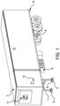
- FIG. 1 is a view in perspective of a semi-trailer electric battery powered reefer with a battery and TRU.
- FIG. 2 depicts the landing gear pads located above the parking space charging pads that are connected to the APU.
- FIGS. 3 A and 3 b are top views in perspective of semi-trailer landing gear legs with charging pads and sensors.
- FIGS. 4 A and 4 B show a bottom view of the charging pads with contact electrodes.
- FIG. 5 is a full front view of an electric transport refrigeration unit.
- an automatic system for coupling electric grid power to the landing gear pads of a battery powered semi-trailer electric reefer uses direct electrical contact between the parking surface pad and the trailer landing gear pad. Grid power is used for charging the battery.
- This automatic-battery charging system can work independent of or in combination with a wheel generator mounted on the reefer, a manual grid plug-in or solar panel also mounted reefer.
- a method for automatically, directly, providing electrical power to a battery powered electric semi-trailer reefer comprises providing an auxiliary power source and electrically connecting said auxiliary power source to a parking surface charging pad for each leg of a landing gear for battery powered electric semi-trailer reefer.
- the parking surface charging pad contains an electrode plate in it.
- a landing gear electrical contact pad containing an electrode on a lower end of each leg of the landing gear.
- the landing gear electrical contact pad is electrically connected to a battery located on the battery powered electric semi-trailer reefer. Then, the reefer, with landing gear extended, is moved such that each lower leg and contact pad align and meet with the parking surface pad.
- System useful for this method is a system for automatically, directly, coupling electrical power to a battery electric semi-trailer reefer.
- the system comprises an auxiliary power source electrically connected to parking surface charging pads for each leg of a battery electric semi-trailer reefer landing gear.
- This invention uses the landing gear legs 1 ( FIGS. 1 , 3 A, 3 B, 4 A, and 4 B ) of the semi-trailer to automatically couple the grid.
- FIG. 1 In FIG. 1 , four-battery charging sources are shown, the automatic landing gear pads 6 , manual plug-in 21 , solar panel 3 and wheel generator 4 .
- Autonomous charging is achieved by direct contact where low-voltage DC power 22 in the range of 24 to 48 volts shown in FIG. 2 is coupled via the underground wire 14 to parking lot charging pads 5 .
- Two electrode plates 8 connected to the APU 7 that converts high-voltage grid AC power to safe low-voltage DC power, are mounted in the parking surface pads 5 , positioned to match the dimensions of the semi-trailer landing gear pads 6 .
- the APU is high voltage alternate current 480 volts-3 phase.
- One pad 5 is at ground potential and the other is held at a potential sufficient to charge the battery 9 ( FIG. 1 ).
- Pads 6 at the bottom of the landing gear legs are fitted with contact electrodes 15 shown in FIGS.
- FIGS. 3 A and 3 B that couple to the parking surface pads 5 when the semi-trailer is lowered unto the charging electrode plates 8 .
- An infrared distance sensor 10 in FIGS. 3 A and 3 B, and 4 A and 4 B sense the proximity of the landing gear pad 6 to the charging pad 5 .
- Compressed air hose 2 FIGS. 4 A, 3 A and 3 B ) then provides a blast of air to clear dirt and debris from the surface of charging pads 5 and electrodes 8 .
- Landing gear leg 1 metal electrode 15 to contact metal charging electrode 8 is anticipated and confirmed by induction proximity switch 11 , sending a signal to the APU 7 to commence charging battery 9 . This completes the hookup of the battery 9 to the APU 7 that converts high-voltage AC grid power to low-voltage DC battery power.
- FIG. 1 there is shown a view in perspective of a battery powered electric semi-trailer reefer 12 with a battery 9 that powers the compressor 19 ( FIG. 5 ), electric motor 18 ( FIG. 5 ), and fan motors 20 ( FIG. 5 ), of the battery electric TRU 17 ( FIG. 5 ) and its electronics 13 ( FIG. 1 ).
- Electric grid power is coupled to the landing gear pads 6 of the reefer 12 using parking surface pads 5 .
- FIG. 2 shows the direct electrical-contact system comprised of an auxiliary power unit (APU) 7 that converts high-voltage AC grid power to low-voltage DC power near 48 volts.
- APU auxiliary power unit
- the low-voltage DC power from the APU 7 is connected by underground wire 14 to the parking surface charging pads 5 .
- This pad is comprised of an electrode plate 8 .
- the reefer trailer 12 is parked so its landing gear pad 6 is within the perimeter of the charging pad surface 5 .
- Shown in FIGS. 4 A and 4 B are contact electrodes 15 that extend to make electrical contact to the charging pad electrodes 8 in pad 5 when the weight of the trailer is placed on the landing gear.
- Grid power is then used by the APU 7 to charge the battery 9 that runs the TRU 17 . Battery 9 is charged via the charging pads 5 and 6 .
- the direct contact automatic-battery charging system can work to charge the battery 9 independent of or in coordination with the solar panel 3 , shore power grid plug-in 21 or the wheel generator 4 .
- This autonomous battery powered electric semi-trailer reefer charging system and method is also applicable to a hybrid battery powered electric semi-trailer reefer where a generator driven by an engine is used to charge the battery.
Landscapes
- Engineering & Computer Science (AREA)
- Mechanical Engineering (AREA)
- Transportation (AREA)
- Power Engineering (AREA)
- Physics & Mathematics (AREA)
- Thermal Sciences (AREA)
- Chemical & Material Sciences (AREA)
- Combustion & Propulsion (AREA)
- Charge And Discharge Circuits For Batteries Or The Like (AREA)
- Electric Propulsion And Braking For Vehicles (AREA)
Abstract
Description
Claims (7)
Priority Applications (1)
| Application Number | Priority Date | Filing Date | Title |
|---|---|---|---|
| US17/385,322 US12012009B2 (en) | 2020-07-29 | 2021-07-26 | Autonomous charging systems for battery powered transport refrigeration units |
Applications Claiming Priority (2)
| Application Number | Priority Date | Filing Date | Title |
|---|---|---|---|
| US202063057963P | 2020-07-29 | 2020-07-29 | |
| US17/385,322 US12012009B2 (en) | 2020-07-29 | 2021-07-26 | Autonomous charging systems for battery powered transport refrigeration units |
Publications (2)
| Publication Number | Publication Date |
|---|---|
| US20220032795A1 US20220032795A1 (en) | 2022-02-03 |
| US12012009B2 true US12012009B2 (en) | 2024-06-18 |
Family
ID=80002697
Family Applications (1)
| Application Number | Title | Priority Date | Filing Date |
|---|---|---|---|
| US17/385,322 Active 2042-08-11 US12012009B2 (en) | 2020-07-29 | 2021-07-26 | Autonomous charging systems for battery powered transport refrigeration units |
Country Status (1)
| Country | Link |
|---|---|
| US (1) | US12012009B2 (en) |
Cited By (1)
| Publication number | Priority date | Publication date | Assignee | Title |
|---|---|---|---|---|
| US20230356645A1 (en) * | 2022-05-09 | 2023-11-09 | Dr. Ing. H.C. F. Porsche Aktiengesellschaft | Mobile apparatus for handling a traction battery of an electric vehicle |
Families Citing this family (1)
| Publication number | Priority date | Publication date | Assignee | Title |
|---|---|---|---|---|
| DE102023123597A1 (en) * | 2023-09-01 | 2025-03-06 | Zf Cv Systems Global Gmbh | Coupling adapter, transfer train and method for transporting a trailer |
Citations (23)
| Publication number | Priority date | Publication date | Assignee | Title |
|---|---|---|---|---|
| US3100384A (en) * | 1960-11-30 | 1963-08-13 | Flextemp Corp | Trailer refrigeration apparatus |
| US4863184A (en) * | 1987-08-28 | 1989-09-05 | Daniel Mena | Tractor-trailer landing gear mechanism and method of using same |
| EP2266831A2 (en) * | 2009-06-26 | 2010-12-29 | Green Alternative Solar LLC | A power generating system for a refrigeration unit of a vehicle |
| US20110114398A1 (en) * | 2009-11-17 | 2011-05-19 | Bianco James S | Battery Power System for Plug In Hybrid Tractor Trailers |
| US20120242060A1 (en) * | 2008-07-23 | 2012-09-27 | Eric Raymond Schubert | Cargo container system with selectively deployable support and wheel assemblies |
| US20160129753A1 (en) * | 2014-11-06 | 2016-05-12 | Ronald Koelsch | Backup Power Generator For Battery Powered Transport Refrigeration Units |
| WO2018219226A1 (en) * | 2017-05-27 | 2018-12-06 | 星逻智能科技(苏州)有限公司 | Unmanned-aerial-vehicle hangar |
| US20190329650A1 (en) * | 2010-10-01 | 2019-10-31 | Emerald Technology Partners, Llc | Stand-alone kinetic energy converter system |
| US20200233410A1 (en) * | 2019-01-22 | 2020-07-23 | Proensis Llc | Electric freight trailer, system and method |
| WO2021222204A1 (en) * | 2020-04-30 | 2021-11-04 | Nova Southeastern University | Supporting trailers |
| CN215154002U (en) * | 2021-08-05 | 2021-12-14 | 河北工业大学 | Automatic charging device of unmanned aerial vehicle and unmanned aerial vehicle |
| US20220111716A1 (en) * | 2020-10-09 | 2022-04-14 | Hexagon Purus North America Holdings Inc. | Battery and auxiliary components for vehicle trailer |
| US20220267127A1 (en) * | 2021-02-19 | 2022-08-25 | Outrider Technologies, Inc. | Jackstand for automated trailer loading dock |
| EP4059841A1 (en) * | 2021-03-18 | 2022-09-21 | Siemens Aktiengesellschaft | Flight drone, base station, flight system and method for electrically charging a flight platform |
| US20220402326A1 (en) * | 2017-02-24 | 2022-12-22 | Ronald Koelsch | Battery powered hybrid transport refrigeration unit |
| US20220410990A1 (en) * | 2021-06-24 | 2022-12-29 | Anamnesis Corporation | System and method for trailer propulsion |
| US20230022717A1 (en) * | 2021-07-20 | 2023-01-26 | Electro Standards Laboratories | Hybrid Power Management System and Method for Delivering Power in a Transport Vehicle |
| GB2609196A (en) * | 2021-07-21 | 2023-02-01 | Sunswap Ltd | Determining battery or solar panel capacity for an electric refrigeration unit |
| WO2023030869A1 (en) * | 2021-09-03 | 2023-03-09 | Sunswap Ltd | Electrical transport refrigeration unit |
| WO2023082025A1 (en) * | 2021-11-15 | 2023-05-19 | Rehouma Fethi | Trailer powerpack with range extender |
| US20230226920A1 (en) * | 2022-01-20 | 2023-07-20 | Hyundai Translead | Regenerative retarder energy system for trailers |
| CN116601045A (en) * | 2020-12-17 | 2023-08-15 | 美国联合金属制品股份有限公司 | Vehicle electronic control unit and method |
| US20230278651A1 (en) * | 2022-03-04 | 2023-09-07 | Cummins Inc. | Trailer for electric truck |
-
2021
- 2021-07-26 US US17/385,322 patent/US12012009B2/en active Active
Patent Citations (24)
| Publication number | Priority date | Publication date | Assignee | Title |
|---|---|---|---|---|
| US3100384A (en) * | 1960-11-30 | 1963-08-13 | Flextemp Corp | Trailer refrigeration apparatus |
| US4863184A (en) * | 1987-08-28 | 1989-09-05 | Daniel Mena | Tractor-trailer landing gear mechanism and method of using same |
| US20120242060A1 (en) * | 2008-07-23 | 2012-09-27 | Eric Raymond Schubert | Cargo container system with selectively deployable support and wheel assemblies |
| EP2266831A2 (en) * | 2009-06-26 | 2010-12-29 | Green Alternative Solar LLC | A power generating system for a refrigeration unit of a vehicle |
| US20110114398A1 (en) * | 2009-11-17 | 2011-05-19 | Bianco James S | Battery Power System for Plug In Hybrid Tractor Trailers |
| US20190329650A1 (en) * | 2010-10-01 | 2019-10-31 | Emerald Technology Partners, Llc | Stand-alone kinetic energy converter system |
| US20160129753A1 (en) * | 2014-11-06 | 2016-05-12 | Ronald Koelsch | Backup Power Generator For Battery Powered Transport Refrigeration Units |
| US9415660B2 (en) * | 2014-11-06 | 2016-08-16 | Ronald Koelsch | Backup power generator for battery powered transport refrigeration units |
| US20220402326A1 (en) * | 2017-02-24 | 2022-12-22 | Ronald Koelsch | Battery powered hybrid transport refrigeration unit |
| WO2018219226A1 (en) * | 2017-05-27 | 2018-12-06 | 星逻智能科技(苏州)有限公司 | Unmanned-aerial-vehicle hangar |
| US20200233410A1 (en) * | 2019-01-22 | 2020-07-23 | Proensis Llc | Electric freight trailer, system and method |
| WO2021222204A1 (en) * | 2020-04-30 | 2021-11-04 | Nova Southeastern University | Supporting trailers |
| US20220111716A1 (en) * | 2020-10-09 | 2022-04-14 | Hexagon Purus North America Holdings Inc. | Battery and auxiliary components for vehicle trailer |
| CN116601045A (en) * | 2020-12-17 | 2023-08-15 | 美国联合金属制品股份有限公司 | Vehicle electronic control unit and method |
| US20220267127A1 (en) * | 2021-02-19 | 2022-08-25 | Outrider Technologies, Inc. | Jackstand for automated trailer loading dock |
| EP4059841A1 (en) * | 2021-03-18 | 2022-09-21 | Siemens Aktiengesellschaft | Flight drone, base station, flight system and method for electrically charging a flight platform |
| US20220410990A1 (en) * | 2021-06-24 | 2022-12-29 | Anamnesis Corporation | System and method for trailer propulsion |
| US20230022717A1 (en) * | 2021-07-20 | 2023-01-26 | Electro Standards Laboratories | Hybrid Power Management System and Method for Delivering Power in a Transport Vehicle |
| GB2609196A (en) * | 2021-07-21 | 2023-02-01 | Sunswap Ltd | Determining battery or solar panel capacity for an electric refrigeration unit |
| CN215154002U (en) * | 2021-08-05 | 2021-12-14 | 河北工业大学 | Automatic charging device of unmanned aerial vehicle and unmanned aerial vehicle |
| WO2023030869A1 (en) * | 2021-09-03 | 2023-03-09 | Sunswap Ltd | Electrical transport refrigeration unit |
| WO2023082025A1 (en) * | 2021-11-15 | 2023-05-19 | Rehouma Fethi | Trailer powerpack with range extender |
| US20230226920A1 (en) * | 2022-01-20 | 2023-07-20 | Hyundai Translead | Regenerative retarder energy system for trailers |
| US20230278651A1 (en) * | 2022-03-04 | 2023-09-07 | Cummins Inc. | Trailer for electric truck |
Cited By (1)
| Publication number | Priority date | Publication date | Assignee | Title |
|---|---|---|---|---|
| US20230356645A1 (en) * | 2022-05-09 | 2023-11-09 | Dr. Ing. H.C. F. Porsche Aktiengesellschaft | Mobile apparatus for handling a traction battery of an electric vehicle |
Also Published As
| Publication number | Publication date |
|---|---|
| US20220032795A1 (en) | 2022-02-03 |
Similar Documents
| Publication | Publication Date | Title |
|---|---|---|
| US12012009B2 (en) | Autonomous charging systems for battery powered transport refrigeration units | |
| US4158802A (en) | Rechargeable battery powered electric car and recharging station therefor | |
| CN105896695B (en) | Electric bus station suspended wireless charging system | |
| US11433775B1 (en) | Aircraft charging unit | |
| US12611953B2 (en) | Delivery truck with charge capability | |
| US20200385075A1 (en) | Method and vehicle for conveying an electrically driven motor vehicle during assembly thereof | |
| CN202320042U (en) | Emergency charging square cabin of pickup truck | |
| US20160137076A1 (en) | System, method and apparatus for remote opportunity charging | |
| CN205970886U (en) | A battery charging outfit for electrically driven (operated) vehicle | |
| CN203720274U (en) | Movable-type detection device for transformer-like equipment | |
| US20250239882A1 (en) | Mobile Power Station | |
| CN104192098A (en) | System scheme for rapidly replacing power battery box of electric motor coach | |
| CN204250001U (en) | The quick electrical changing station of a kind of electrobus, for electrical changing station on-vehicle battery cabin and be common to the battery box in electrical changing station and on-vehicle battery cabin | |
| CN103630783B (en) | Transformer ' s type equipment moving formula checkout gear | |
| CN201165202Y (en) | Mine explosion-proof super capacitor energy storage type hauling engine | |
| CN103625346A (en) | Movable detection device for equipment such as switch cabinet | |
| CN208978850U (en) | It can self-stopping electric track flatcar | |
| CN217435544U (en) | Charging mechanism for battery box distribution vehicle | |
| CN106394928B (en) | Double-power containerized cargo loader for airport | |
| CN206125108U (en) | Special transport vechicle of unmanned type | |
| CN206554567U (en) | A kind of intelligent vehicle bearing pallet system of multi-storied garage automatic charging | |
| CN205104945U (en) | Automatic energy supply system of guide transport vechicle | |
| CN205577546U (en) | Charging device and stereo garage | |
| CN211416971U (en) | High-voltage connection system of pure electric pickup | |
| CN205524279U (en) | Track operation car |
Legal Events
| Date | Code | Title | Description |
|---|---|---|---|
| FEPP | Fee payment procedure |
Free format text: ENTITY STATUS SET TO UNDISCOUNTED (ORIGINAL EVENT CODE: BIG.); ENTITY STATUS OF PATENT OWNER: SMALL ENTITY |
|
| FEPP | Fee payment procedure |
Free format text: ENTITY STATUS SET TO SMALL (ORIGINAL EVENT CODE: SMAL); ENTITY STATUS OF PATENT OWNER: SMALL ENTITY |
|
| STPP | Information on status: patent application and granting procedure in general |
Free format text: DOCKETED NEW CASE - READY FOR EXAMINATION |
|
| AS | Assignment |
Owner name: ADVANCED ENERGY MACHINES, LLC, ARIZONA Free format text: ASSIGNMENT OF ASSIGNORS INTEREST;ASSIGNORS:SHEA, RAYMOND JAMES, JR;KOELSCH, RONALD;BONGIORNO, FRANK, III;SIGNING DATES FROM 20220121 TO 20220124;REEL/FRAME:059060/0906 |
|
| STPP | Information on status: patent application and granting procedure in general |
Free format text: NON FINAL ACTION MAILED |
|
| STPP | Information on status: patent application and granting procedure in general |
Free format text: RESPONSE TO NON-FINAL OFFICE ACTION ENTERED AND FORWARDED TO EXAMINER |
|
| STPP | Information on status: patent application and granting procedure in general |
Free format text: NOTICE OF ALLOWANCE MAILED -- APPLICATION RECEIVED IN OFFICE OF PUBLICATIONS |
|
| STPP | Information on status: patent application and granting procedure in general |
Free format text: PUBLICATIONS -- ISSUE FEE PAYMENT VERIFIED |
|
| STCF | Information on status: patent grant |
Free format text: PATENTED CASE |
|
| AS | Assignment |
Owner name: AMERICAN ALTERNATIVE ENERGY PRODUCTS, NEVADA Free format text: ASSIGNMENT OF ASSIGNORS INTEREST;ASSIGNOR:ADVANCED ENERGY MACHINES, LLC;REEL/FRAME:068379/0455 Effective date: 20240805 |